developing breakout models in femap - structural · pdf file5/22/2012 page 1 developing...
TRANSCRIPT
5/22/2012Page 1
Developing Breakout Models in FEMAP
This presentation includes:
• Definition of Breakout Models
• When to use breakouts
• [Tutorial] Adding a pass-through in a wing rib
• [Tutorial] Adding boss to orthogrid pressure plate
Presenter: Ryan Tatman
5/22/2012Page 2Page 2
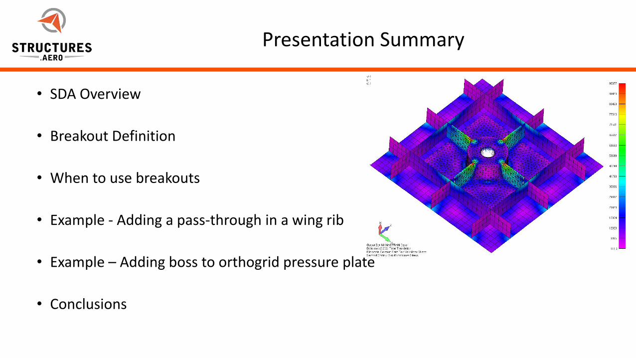
Presentation Summary
• SDA Overview
• Breakout Definition
• When to use breakouts
• Example - Adding a pass-through in a wing rib
• Example – Adding boss to orthogrid pressure plate
• Conclusions
5/22/2012Page 3Page 3
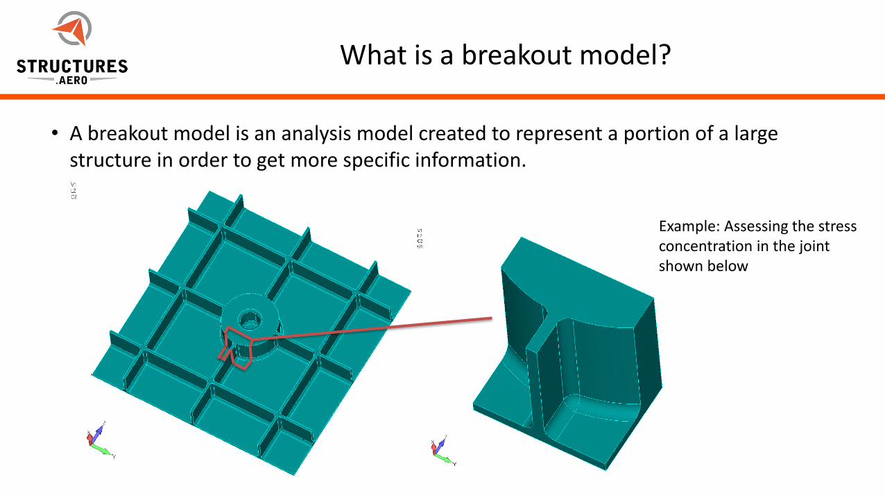
What is a breakout model?
• A breakout model is an analysis model created to represent a portion of a large structure in order to get more specific information.
Example: Assessing the stress concentration in the joint shown below
5/22/2012Page 4Page 4
When is a breakout model needed?
• When a small design change requires analysis
– When a small portion of a large design needs to be iteratively designed
– When a feature is added to an existing part
• When examination of localized stress risers is needed
– When the size of a model does not allow for the fidelity needed in specific locations
– When stress information is needed for a fillet or pad-up in a plate model
5/22/2012Page 5Page 5
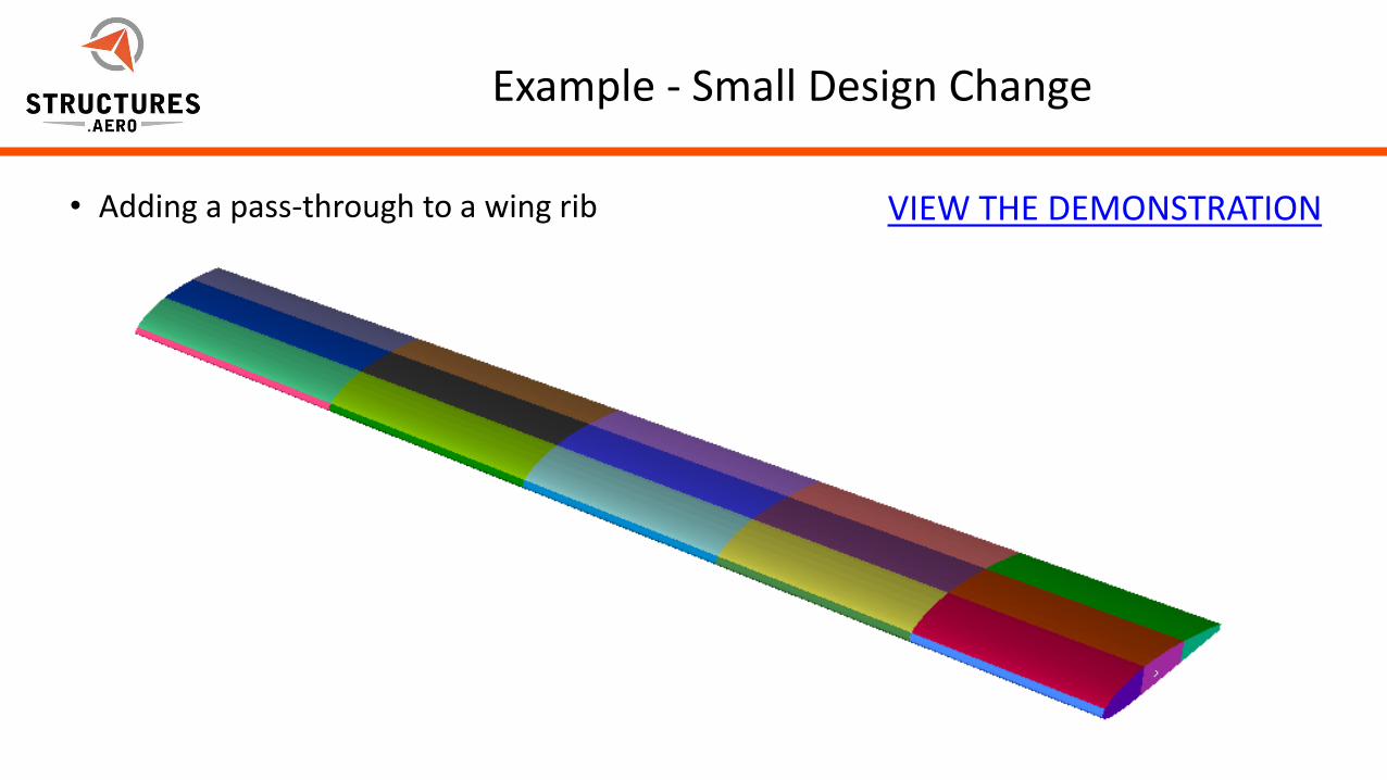
Example - Small Design Change
• Adding a pass-through to a wing rib VIEW THE DEMONSTRATION
5/22/2012Page 6Page 6
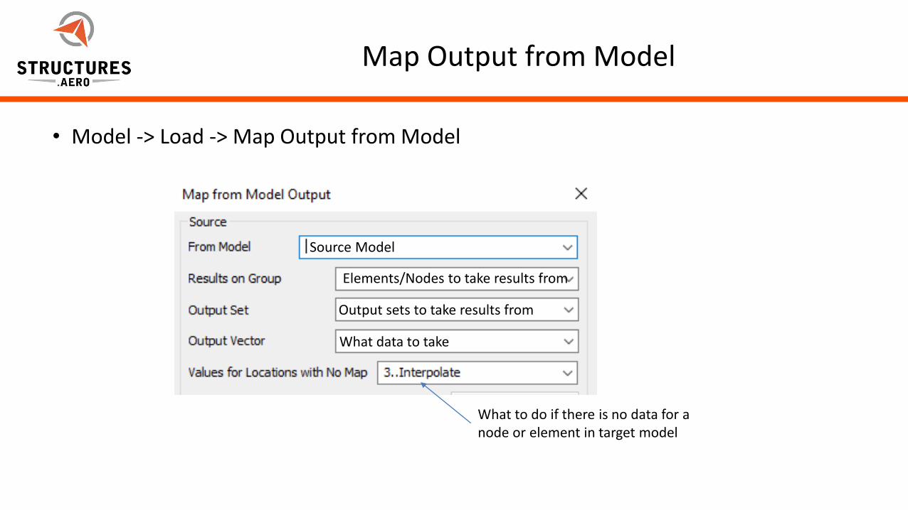
Map Output from Model
• Model -> Load -> Map Output from Model
Source Model
Elements/Nodes to take results from
Output sets to take results from
What data to take
What to do if there is no data for a node or element in target model
5/22/2012Page 7Page 7
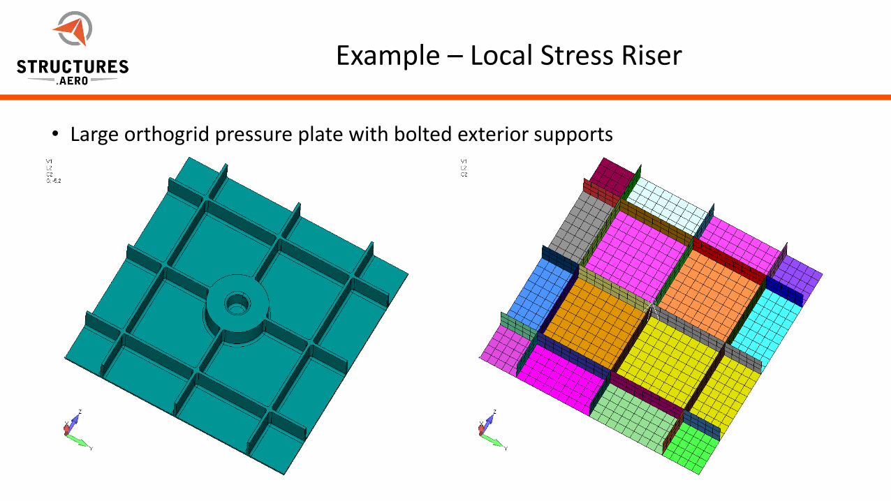
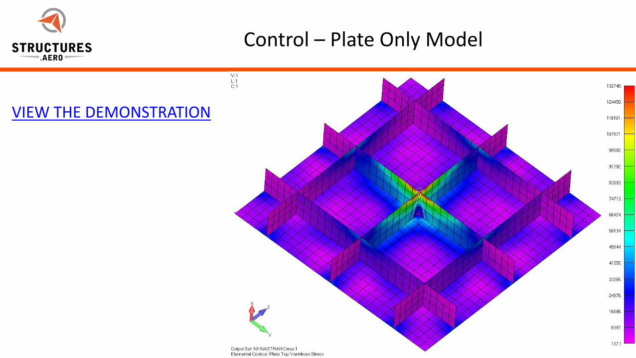
Example – Local Stress Riser
• Large orthogrid pressure plate with bolted exterior supports
5/22/2012Page 8Page 8
Popular Options
• Hex-Mesh the area of the model
– No element doubling
– Element penetration
– Element skins
• Pull nodal displacements and rotations from the analysis and create SPCDs to apply on solid meshed breakout
• Integrate solid meshed breakout into full model
5/22/2012Page 9Page 9
Control – Plate Only Model
VIEW THE DEMONSTRATION

5/22/2012Page 10Page 10
Control – Full Solid Model
VIEW THE DEMONSTRATION
5/22/2012Page 11Page 11
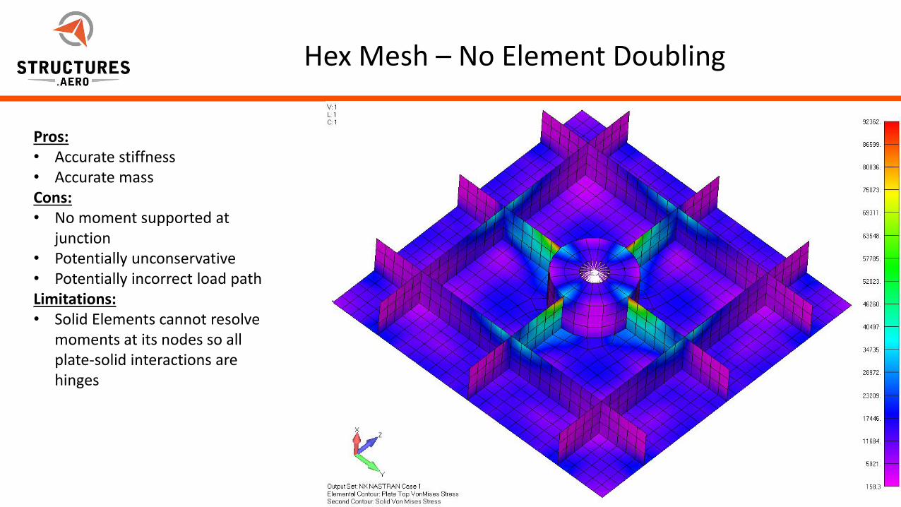
Hex Mesh – No Element Doubling
Pros:• Accurate stiffness• Accurate massCons:• No moment supported at
junction• Potentially unconservative• Potentially incorrect load pathLimitations:• Solid Elements cannot resolve
moments at its nodes so all plate-solid interactions are hinges
5/22/2012Page 12Page 12
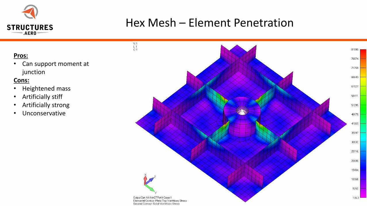
Hex Mesh – Element Penetration
Pros:• Can support moment at
junctionCons:• Heightened mass• Artificially stiff• Artificially strong• Unconservative
5/22/2012Page 13Page 13
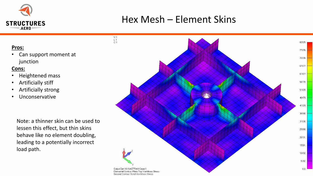
Hex Mesh – Element Skins
Pros:• Can support moment at
junctionCons:• Heightened mass• Artificially stiff• Artificially strong• Unconservative
Note: a thinner skin can be used to lessen this effect, but thin skins behave like no element doubling, leading to a potentially incorrect load path.
5/22/2012Page 14Page 14
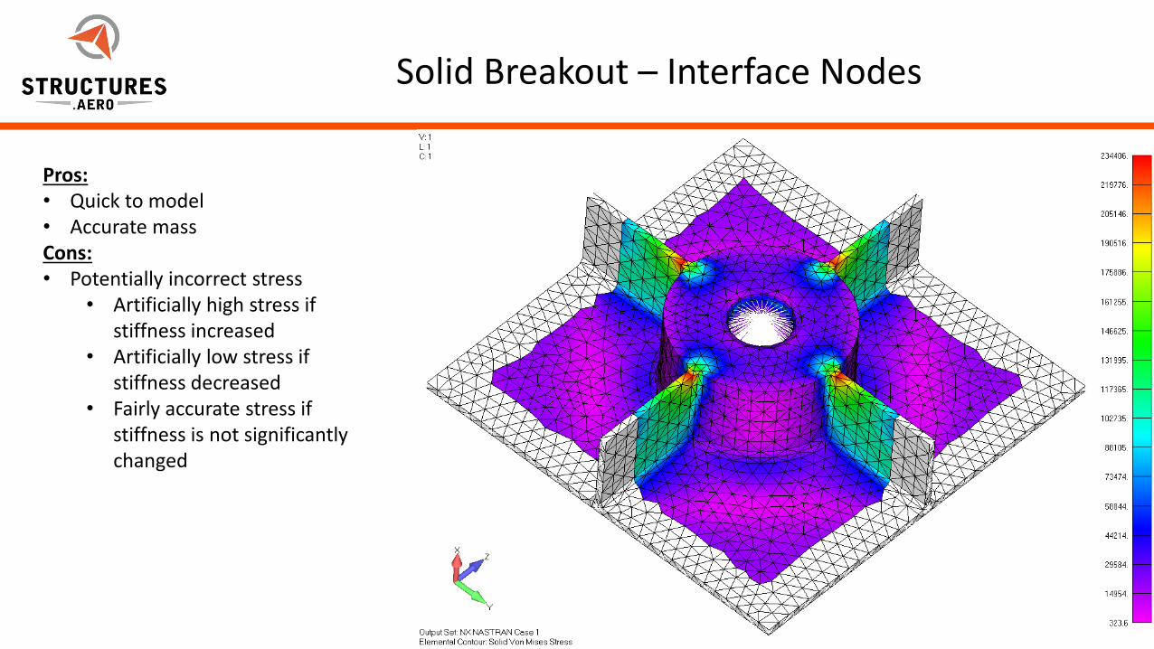
Solid Breakout – Interface Nodes
Pros:• Quick to model• Accurate massCons:• Potentially incorrect stress
• Artificially high stress if stiffness increased
• Artificially low stress if stiffness decreased
• Fairly accurate stress if stiffness is not significantly changed
5/22/2012Page 15Page 15
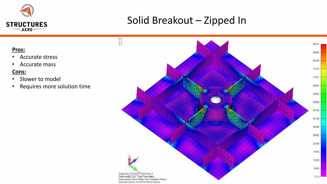
Solid Breakout – Zipped In
Pros:• Accurate stress • Accurate massCons:• Slower to model• Requires more solution time
5/22/2012Page 16Page 16
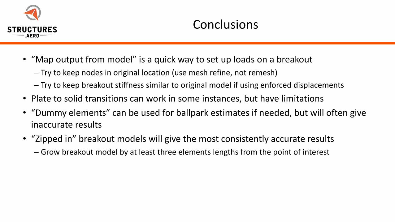
Conclusions
• “Map output from model” is a quick way to set up loads on a breakout
– Try to keep nodes in original location (use mesh refine, not remesh)
– Try to keep breakout stiffness similar to original model if using enforced displacements
• Plate to solid transitions can work in some instances, but have limitations
• “Dummy elements” can be used for ballpark estimates if needed, but will often give inaccurate results
• “Zipped in” breakout models will give the most consistently accurate results
– Grow breakout model by at least three elements lengths from the point of interest
5/22/2012Page 17Page 17
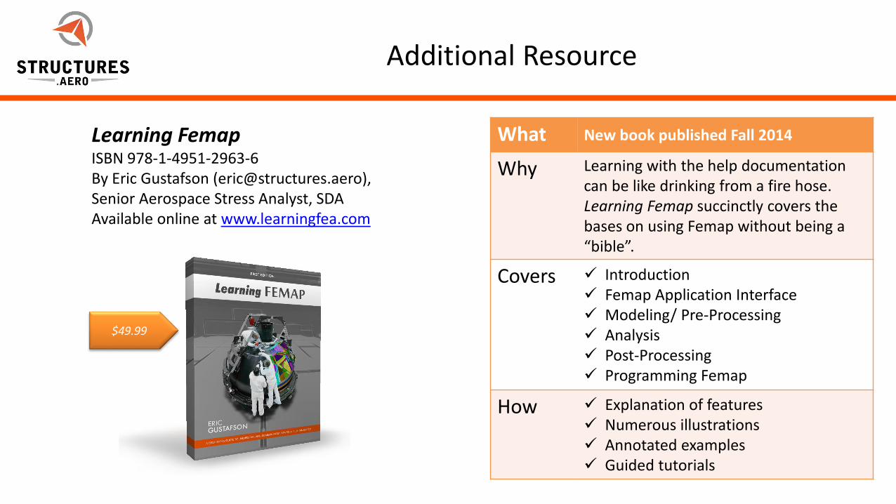
Additional Resource
What New book published Fall 2014
Why Learning with the help documentation can be like drinking from a fire hose. Learning Femap succinctly covers the bases on using Femap without being a “bible”.
Covers Introduction Femap Application Interface Modeling/ Pre-Processing Analysis Post-Processing Programming Femap
How Explanation of features Numerous illustrations Annotated examples Guided tutorials
Learning FemapISBN 978-1-4951-2963-6By Eric Gustafson ([email protected]), Senior Aerospace Stress Analyst, SDAAvailable online at www.learningfea.com
$49.99
5/22/2012Page 18Page 18
Contact Us:
Contact:
Marty Sivic
Email:[email protected]
Website:http://structures.aero/
Phone: (724) 382-5290
Try FEMAP For Free!
Download a free 45-day trial of FEMAP with NX Nastran
• Full FEMAP capabilities• All Nastran solution sequences included• (http://structures.aero/femap-trial/)
Presenter:
Ryan Tatman
Email:[email protected]
Website:http://structures.aero/
Phone: (703) 935-2818

5/22/2012Page 19
About SDA (aka “Structures.Aero”)
• SDA was founded in 1997 and provides expert aerospace structural analysis
• We serve a variety of industries
• We specialize in composites, and developing strong, lightweight structures that are readily manufacturable
• Low level support up through developing test plans and advanced stress analysis
• Typical support programs include small to large UAVs, manned and unmanned spacecraft, naval structures
• Our team consists of over a dozen B.S., M.S., and PhD level engineers
• SDA is located in Sterling, VA, just north of Dulles Airport near Washington DC
Learn more about
Structural Design and Analysis
5/22/2012Page 20Page 20
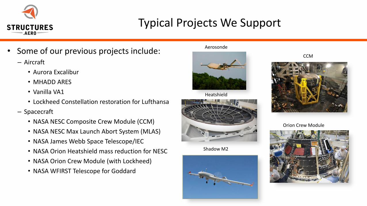
Typical Projects We Support
• Some of our previous projects include:– Aircraft
• Aurora Excalibur
• MHADD ARES
• Vanilla VA1
• Lockheed Constellation restoration for Lufthansa
– Spacecraft
• NASA NESC Composite Crew Module (CCM)
• NASA NESC Max Launch Abort System (MLAS)
• NASA James Webb Space Telescope/IEC
• NASA Orion Heatshield mass reduction for NESC
• NASA Orion Crew Module (with Lockheed)
• NASA WFIRST Telescope for Goddard
Aerosonde
Heatshield
Shadow M2
CCM
Orion Crew Module
5/22/2012Page 21Page 21
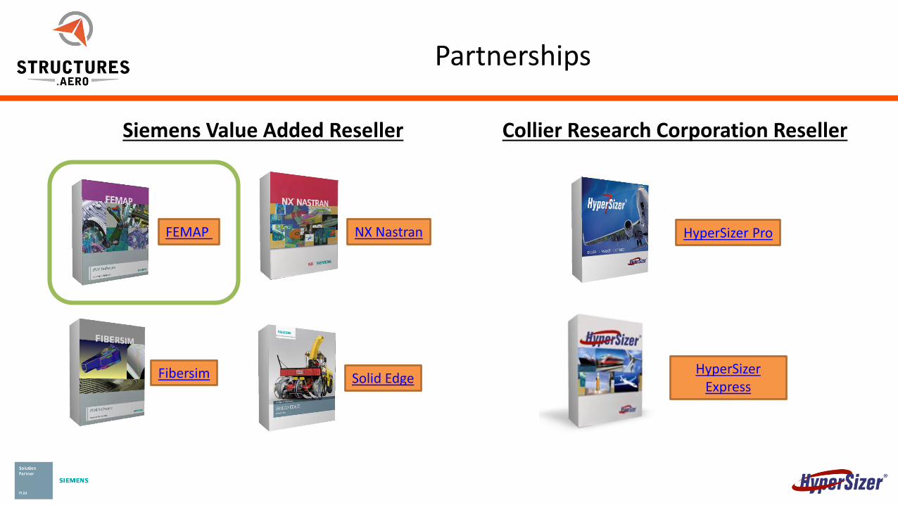
Partnerships
Siemens Value Added Reseller Collier Research Corporation Reseller
FEMAP NX Nastran
Fibersim Solid Edge
HyperSizer Pro
HyperSizerExpress

5/22/2012Page 22
APPENDIX: TUTORIAL WALKTHROUGHS
5/22/2012Page 23Page 23
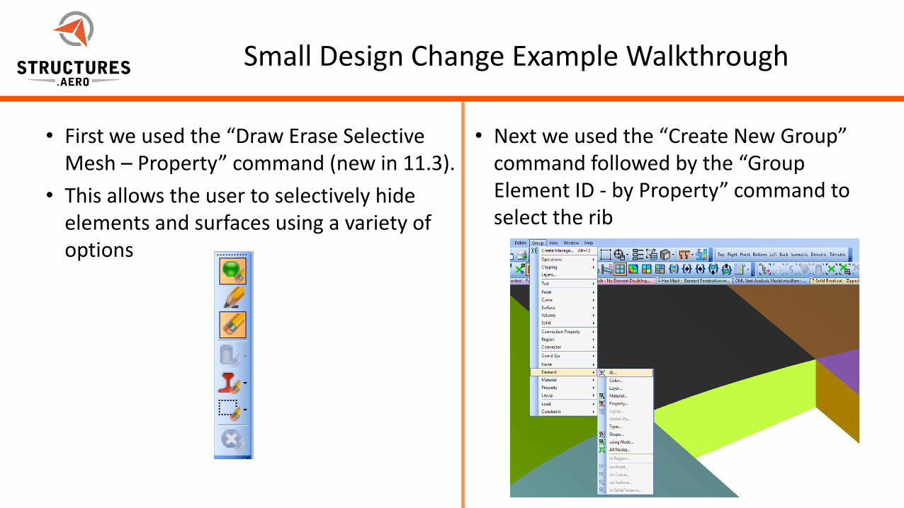
Small Design Change Example Walkthrough
• First we used the “Draw Erase Selective Mesh – Property” command (new in 11.3).
• This allows the user to selectively hide elements and surfaces using a variety of options
• Next we used the “Create New Group” command followed by the “Group Element ID - by Property” command to select the rib
5/22/2012Page 24Page 24
Small Design Change Example Walkthrough
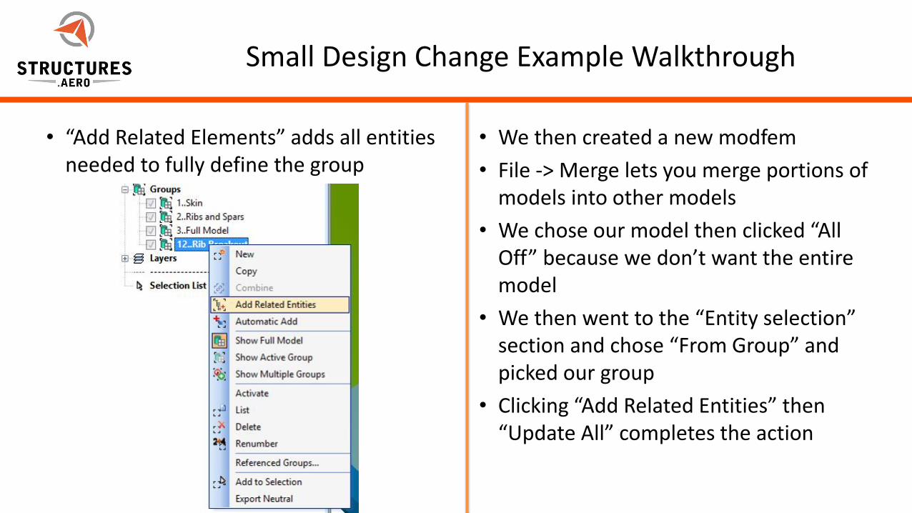
• “Add Related Elements” adds all entities needed to fully define the group
• We then created a new modfem
• File -> Merge lets you merge portions of models into other models
• We chose our model then clicked “All Off” because we don’t want the entire model
• We then went to the “Entity selection” section and chose “From Group” and picked our group
• Clicking “Add Related Entities” then “Update All” completes the action
5/22/2012Page 25Page 25
Small Design Change Example Walkthrough
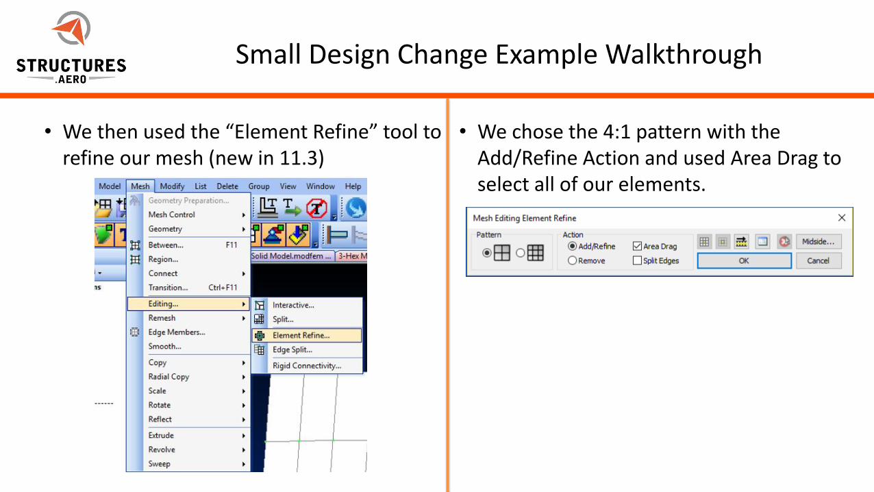
• We then used the “Element Refine” tool to refine our mesh (new in 11.3)
• We chose the 4:1 pattern with the Add/Refine Action and used Area Drag to select all of our elements.
5/22/2012Page 26Page 26
Small Design Change Example Walkthrough
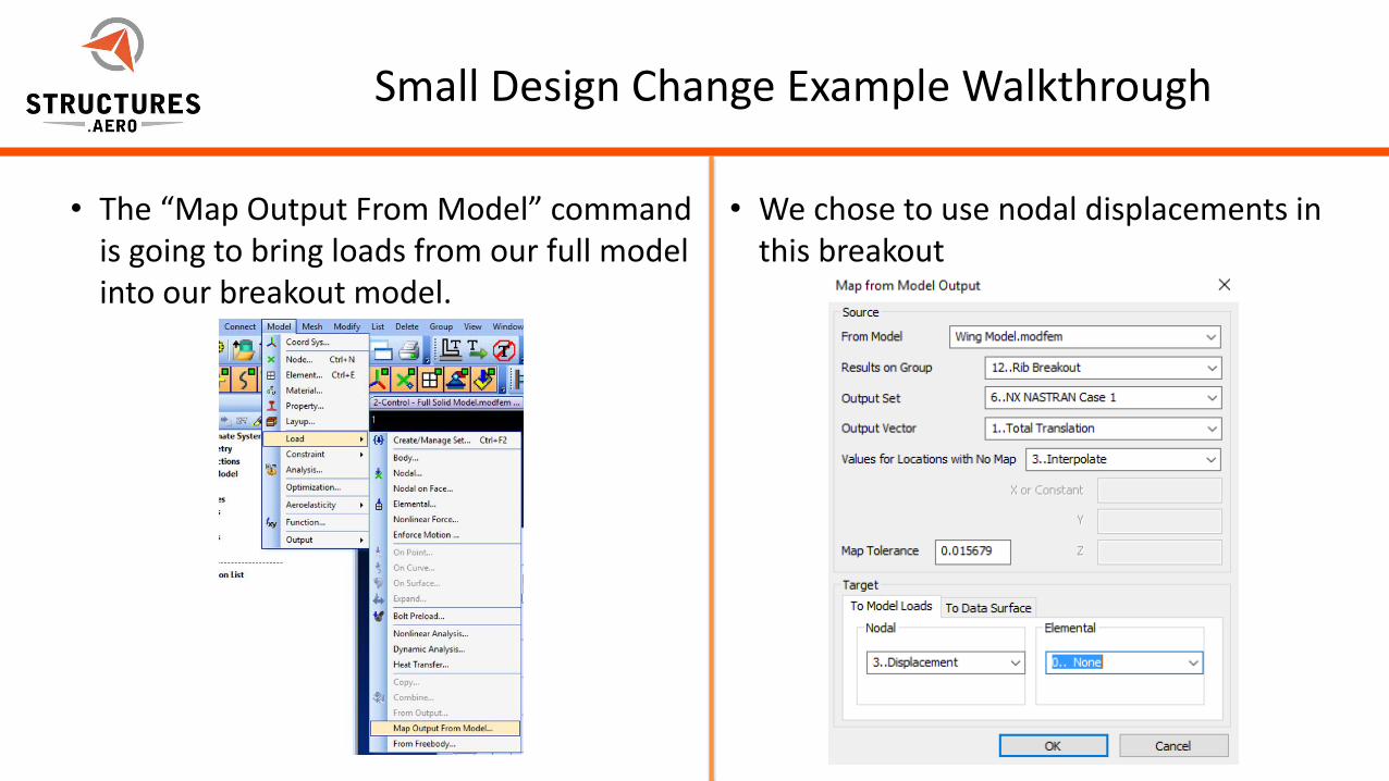
• The “Map Output From Model” command is going to bring loads from our full model into our breakout model.
• We chose to use nodal displacements in this breakout
5/22/2012Page 27Page 27
Small Design Change Example Walkthrough
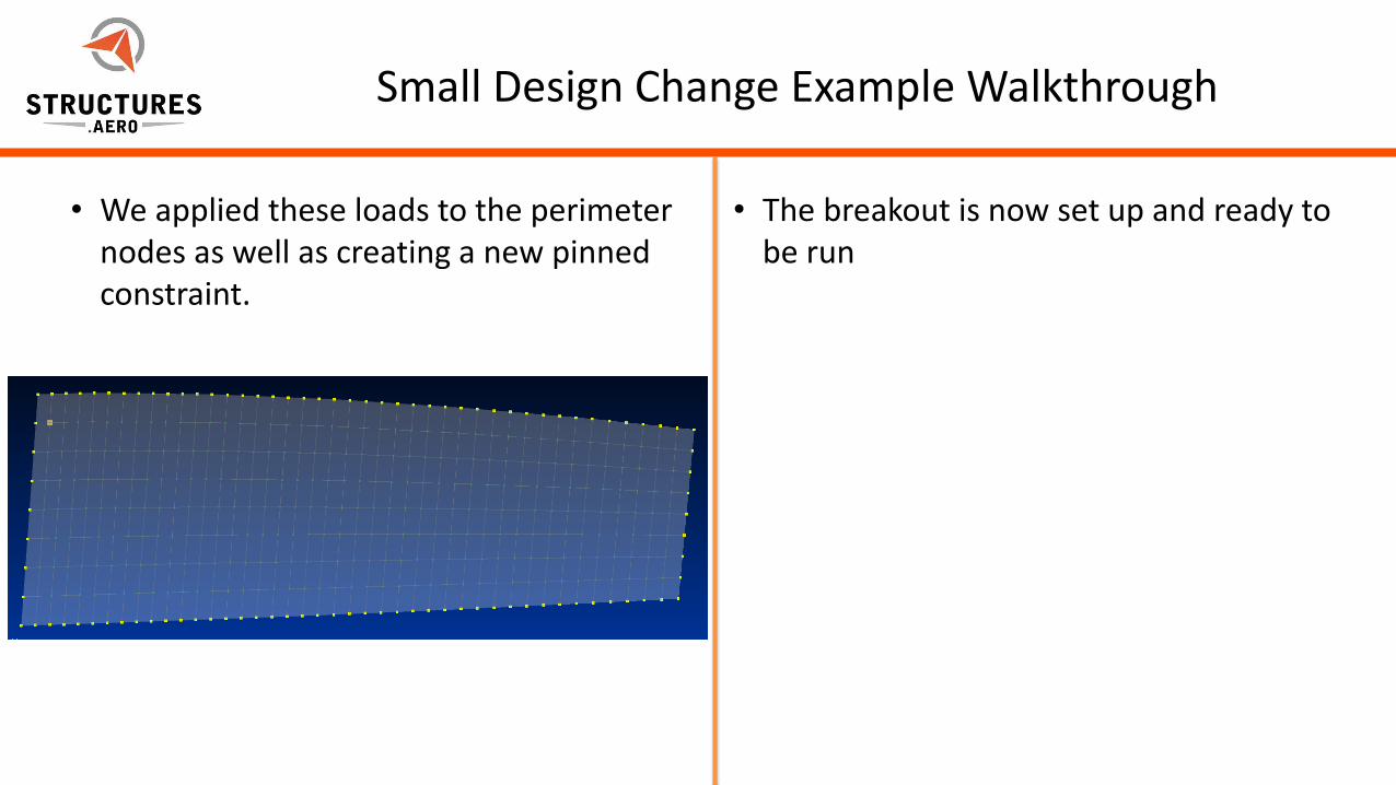
• We applied these loads to the perimeter nodes as well as creating a new pinned constraint.
• The breakout is now set up and ready to be run
5/22/2012Page 28Page 28
Local Stress Riser Example Walkthrough
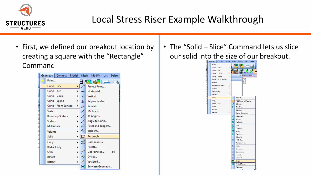
• First, we defined our breakout location by creating a square with the “Rectangle” Command
• The “Solid – Slice” Command lets us slice our solid into the size of our breakout.
5/22/2012Page 29Page 29
Local Stress Riser Example Walkthrough
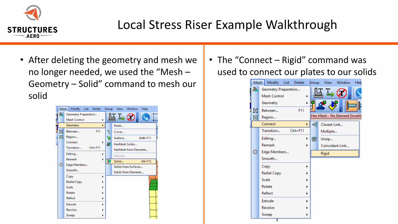
• After deleting the geometry and mesh we no longer needed, we used the “Mesh –Geometry – Solid” command to mesh our solid
• The “Connect – Rigid” command was used to connect our plates to our solids
5/22/2012Page 30Page 30
Local Stress Riser Example Walkthrough
• The source nodes are on the plate elements and the target nodes are on the solid elements
• We used RBE2s in the webinar, but RBE3s can be used as well. Which RBE to use can depend on its application in your breakout
• The bolt interface RBE was updated to connect to the new solid mesh using the “Modify – Edit – Element” Command.
• The model is finished and ready to run