dislocations & strengthening...
TRANSCRIPT
Chapter 9 - 1
학습 목표
• 왜 금속에서 전위의 수가 중요한가?
• 강도와 전위 운동은 어떤 관계를 가지는 것인가?
• 왜 열처리는 강도와 다른 기계적 성질을 변화 시키는가?
Chapter 9: 전위와 강화기구 (Dislocations & Strengthening
Mechanisms)
Chapter 9 - 2
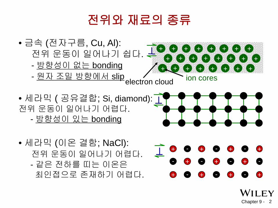
전위와 재료의 종류
• 세라믹 ( 공유결합; Si, diamond): 전위 운동이 일어나기 어렵다. - 방향성이 있는 bonding
• 세라믹 (이온 결함; NaCl): 전위 운동이 일어나기 어렵다. - 같은 전하를 띠는 이온은 최인접으로 존재하기 어렵다.
+ + + +
+ + +
+ + + +
- - -
- - - -
- - -
• 금속 (전자구름, Cu, Al): 전위 운동이 일어나기 쉽다. - 방향성이 없는 bonding - 원자 조밀 방향에서 slip electron cloud ion cores
+ +
+ +
+ + + + + + + + + + + + +
+ + + + + + +

Chapter 9 - 3
전위 운동 (Dislocation Motion)의 기본 개념 전위 운동과 소성 변형 • 금속 – 슬립 (slip)에 의해 소성변형이 일어난다.
– 칼날 전위(edge dislocation): 과잉 반쪽 원자면이 전단 응력에 의해 슬립면을 따라 미끄러지며 같은 쪽의 면을 순차적으로 밀게 된다.
• 전위가 움직이지 못하면, 소성변형이 일어나지 않는다.
Fig. 9.1, Callister & Rethwisch 9e. (Adapted from A. G. Guy, Essentials of Materials Science, McGraw-Hill Book Company, New York, 1976, p. 153.)
Chapter 9 - 4
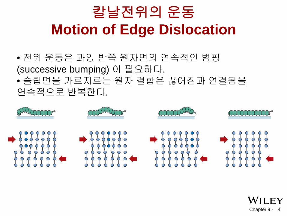
• 전위 운동은 과잉 반쪽 원자면의 연속적인 범핑 (successive bumping) 이 필요하다. • 슬립면을 가로지르는 원자 결합은 끊어짐과 연결됨을 연속적으로 반복한다.
칼날전위의 운동 Motion of Edge Dislocation
Chapter 9 - 5
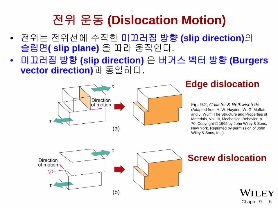
전위 운동 (Dislocation Motion) • 전위는 전위선에 수직한 미끄러짐 방향 (slip direction)의 슬립면( slip plane) 을 따라 움직인다.
• 미끄러짐 방향 (slip direction) 은 버거스 벡터 방향 (Burgers vector direction)과 동일하다.
Edge dislocation
Screw dislocation
Fig. 9.2, Callister & Rethwisch 9e. (Adapted from H. W. Hayden, W. G. Moffatt, and J. Wulff, The Structure and Properties of Materials, Vol. III, Mechanical Behavior, p. 70. Copyright © 1965 by John Wiley & Sons, New York. Reprinted by permission of John Wiley & Sons, Inc.)

Chapter 9 - 6
슬립계 (Slip System) – 슬립면 (Slip plane) – 미끄러짐이 일어나기 쉬운 면
• 가장 조밀한 원자 충진 밀도 ( 면간 간격이 크다) – 슬립 방향 (Slip directions) – 미끄러짐이 잘 일어나는 방향
• 최소 선형 원자 밀도
변형 기구 (Deformation Mechanisms)
Fig. 9.6, Callister & Rethwisch 9e.
– FCC의 슬립은 {111} 면에서 일어나고 방향은 <110> 방향이다. (close-packed)
=> FCC의 슬립계는 총 12 개이다. – BCC & HCP 는 다른 슬립 시스템이 있다. (표9.1)

Chapter 9 - 7
단결정의 슬립- 응력과 전위운동 • 분해 전단 응력 (Resolved shear stress, τR)
– 작용된 인장 응력(tensile stress)으로부터 생긴다.
slip plane normal, ns
Resolved shear stress: τR = F s /A s
AS
τR
τR
FS
Relation between σ and τR
τR = FS /AS
F cos λ A / cos ϕ
λ F
FS
ϕ nS
AS A
Applied tensile stress: = F/A σ
F A
F
Chapter 9 - 8
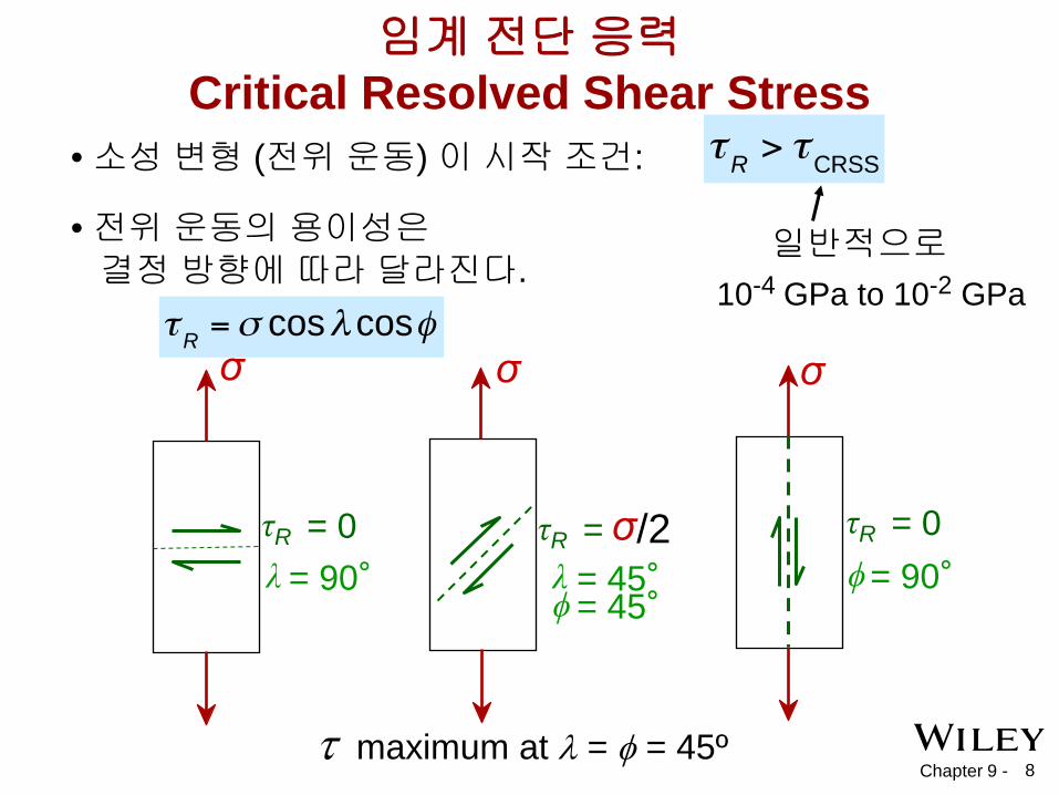
• 소성 변형 (전위 운동) 이 시작 조건:
• 전위 운동의 용이성은 결정 방향에 따라 달라진다.
10-4 GPa to 10-2 GPa 일반적으로
임계 전단 응력 Critical Resolved Shear Stress
τ maximum at λ = φ = 45º
τR = 0 λ = 90°
σ
τR = σ /2 λ = 45° ϕ = 45°
σ
τR = 0 ϕ = 90°
σ
Chapter 9 - 9
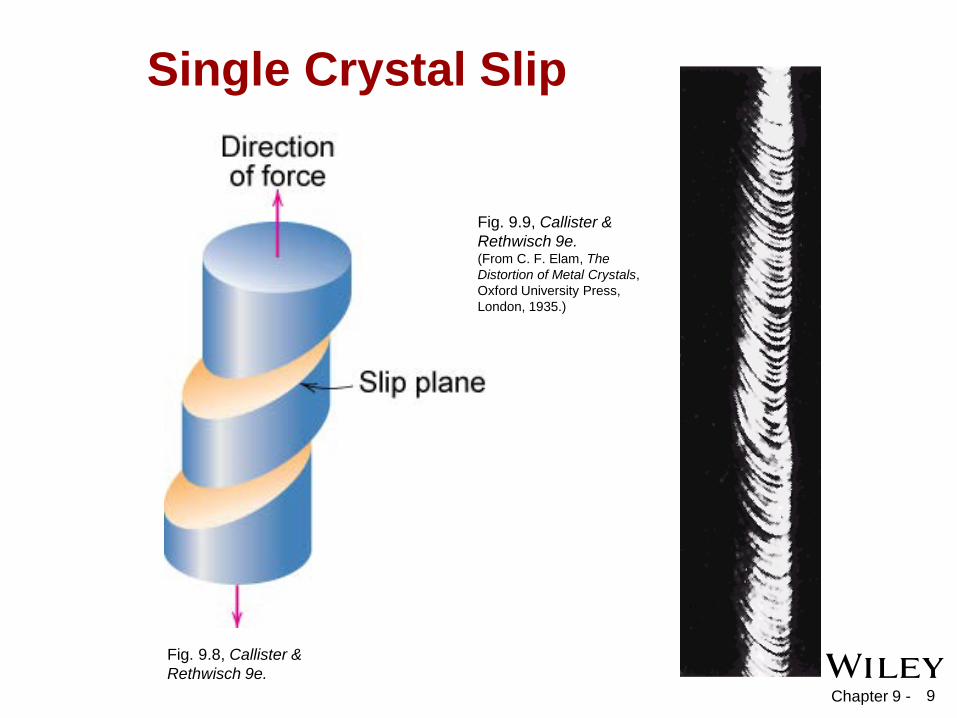
Single Crystal Slip
Fig. 9.8, Callister & Rethwisch 9e.
Fig. 9.9, Callister & Rethwisch 9e. (From C. F. Elam, The Distortion of Metal Crystals, Oxford University Press, London, 1935.)
Chapter 9 - 10
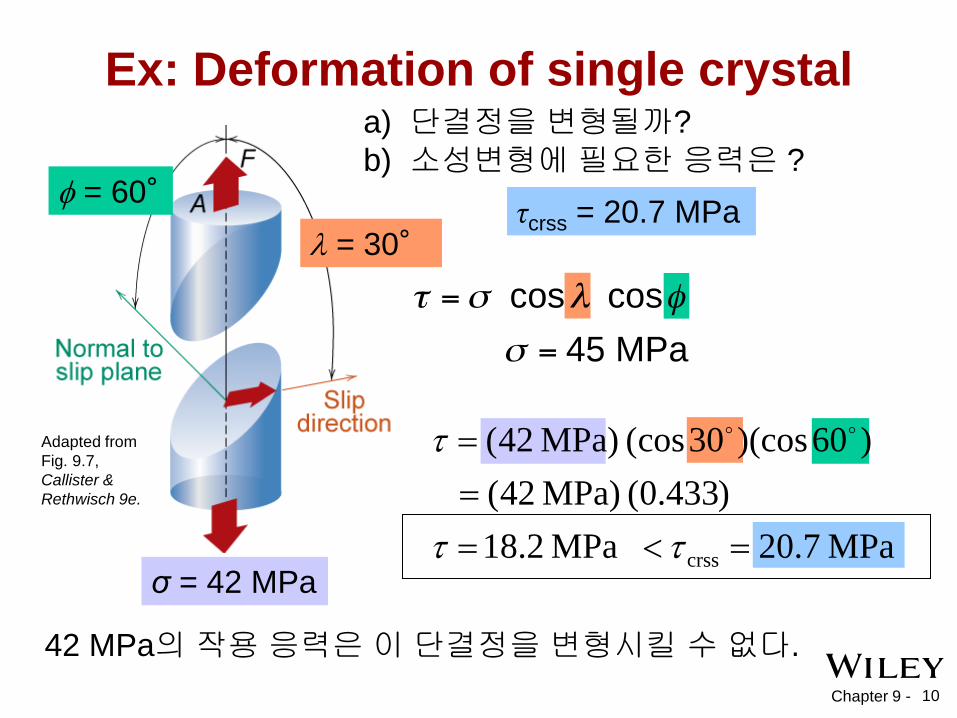
Ex: Deformation of single crystal
42 MPa의 작용 응력은 이 단결정을 변형시킬 수 없다.
λ = 30° φ = 60° τcrss = 20.7 MPa
a) 단결정을 변형될까? b) 소성변형에 필요한 응력은 ?
σ = 42 MPa
Adapted from Fig. 9.7, Callister & Rethwisch 9e.
MPa 7.20 MPa 2.18)433.0( MPa) 42(
)60)(cos30cos( MPa) 42(
crss =<===
ττ
τ
Chapter 9 -
MPa 7.84433.0MPa 0.72
coscoscrss ===∴
ϕλτσ y
11
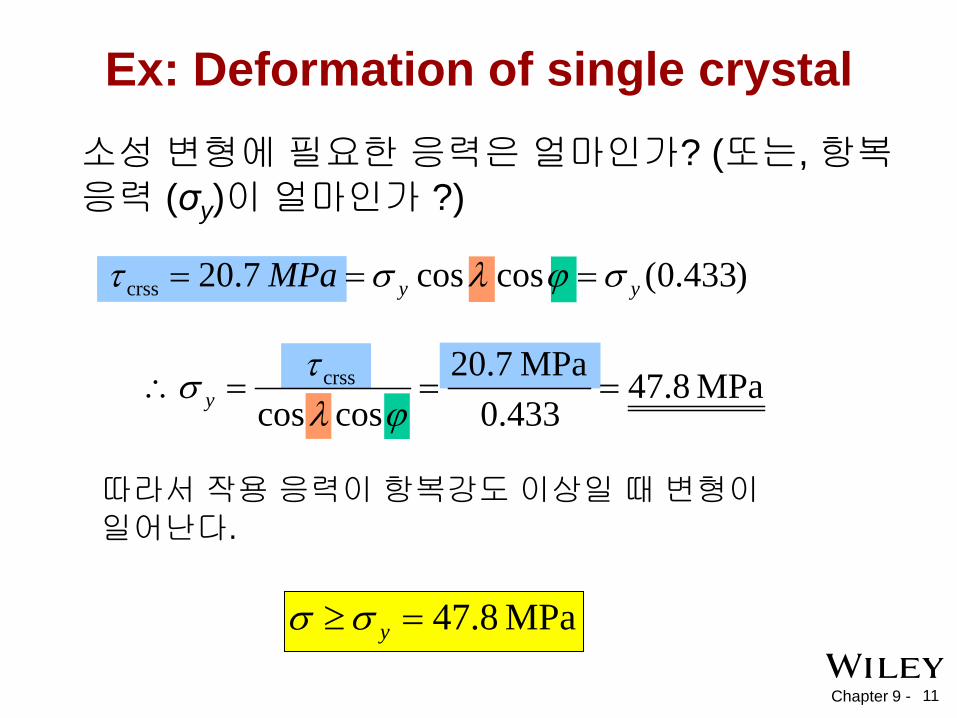
Ex: Deformation of single crystal 소성 변형에 필요한 응력은 얼마인가? (또는, 항복 응력 (σy)이 얼마인가 ?)
)433.0(cos cos 7.20crss yyMPa σϕλστ ===
MPa 8.47=≥ yσσ
따라서 작용 응력이 항복강도 이상일 때 변형이 일어난다.
Chapter 9 - 12
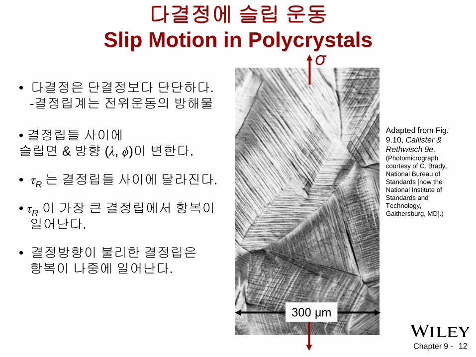
Adapted from Fig. 9.10, Callister & Rethwisch 9e. (Photomicrograph courtesy of C. Brady, National Bureau of Standards [now the National Institute of Standards and Technology, Gaithersburg, MD].)
다결정에 슬립 운동 Slip Motion in Polycrystals
σ
300 μm
• 다결정은 단결정보다 단단하다. -결정립계는 전위운동의 방해물 • 결정립들 사이에 슬립면 & 방향 (λ, ϕ)이 변한다. • τR 는 결정립들 사이에 달라진다. • τR 이 가장 큰 결정립에서 항복이 일어난다. • 결정방향이 불리한 결정립은 항복이 나중에 일어난다.
Chapter 9 - 13
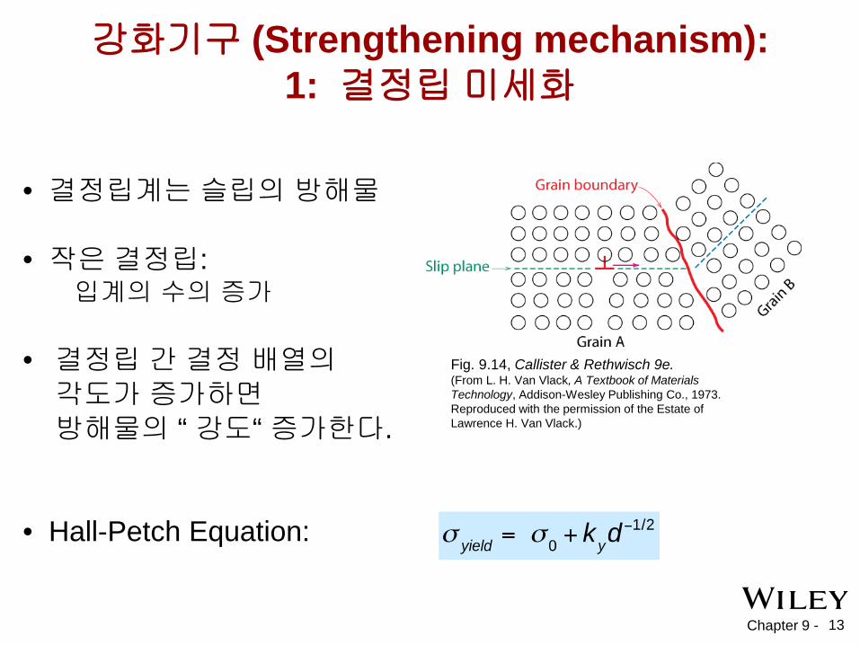
강화기구 (Strengthening mechanism): 1: 결정립 미세화
• 결정립계는 슬립의 방해물 • 작은 결정립: 입계의 수의 증가 • 결정립 간 결정 배열의 각도가 증가하면 방해물의 “ 강도“ 증가한다.
• Hall-Petch Equation:
Fig. 9.14, Callister & Rethwisch 9e. (From L. H. Van Vlack, A Textbook of Materials Technology, Addison-Wesley Publishing Co., 1973. Reproduced with the permission of the Estate of Lawrence H. Van Vlack.)
Chapter 9 - 14
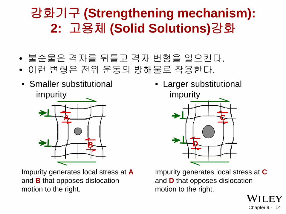
강화기구 (Strengthening mechanism): 2: 고용체 (Solid Solutions)강화
• Smaller substitutional impurity
Impurity generates local stress at A and B that opposes dislocation motion to the right.
A
B
• Larger substitutional impurity
Impurity generates local stress at C and D that opposes dislocation motion to the right.
C
D
• 불순물은 격자를 뒤틀고 격자 변형을 일으킨다. • 이런 변형은 전위 운동의 방해물로 작용한다.
Chapter 9 - 15
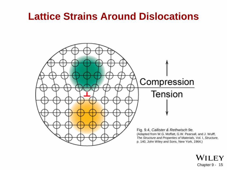
Lattice Strains Around Dislocations
Fig. 9.4, Callister & Rethwisch 9e. (Adapted from W.G. Moffatt, G.W. Pearsall, and J. Wulff, The Structure and Properties of Materials, Vol. I, Structure, p. 140, John Wiley and Sons, New York, 1964.)
Chapter 9 - 16
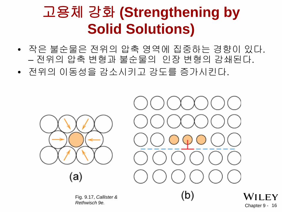
고용체 강화 (Strengthening by Solid Solutions)
• 작은 불순물은 전위의 압축 영역에 집중하는 경향이 있다. – 전위의 압축 변형과 불순물의 인장 변형의 감쇄된다.
• 전위의 이동성을 감소시키고 강도를 증가시킨다.
Fig. 9.17, Callister & Rethwisch 9e.
Chapter 9 - 17
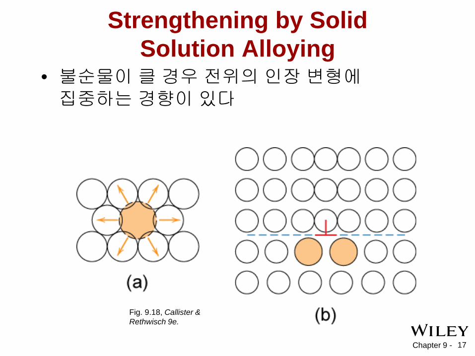
Strengthening by Solid Solution Alloying
• 불순물이 클 경우 전위의 인장 변형에 집중하는 경향이 있다
Fig. 9.18, Callister & Rethwisch 9e.

Chapter 9 - 18
Ex: Cu의 고용체 강화
• Ni 함유량과 함께 인장 강도& 항복강도가 증가한다.
• 합금의 이종 원자는 σy 와 TS를 증가시킴.
Adapted from Fig. 9.16 (a) and (b), Callister & Rethwisch 9e.
Tens
ile s
treng
th (M
Pa)
wt.% Ni, (Concentration C)
200
300
400
0 10 20 30 40 50 Yiel
d st
reng
th (M
Pa)
wt.%Ni, (Concentration C)
60
120
180
0 10 20 30 40 50

Chapter 9 - 19
강화기구 (Strengthening mechanism): 3: 냉간가공 ( 변형 경화)
• 일반적으로 실온에서의 변형. • 일반적인 성형 작업은 단면적을 감소시킨다. :
Adapted from Fig. 17.2, Callister & Rethwisch 9e.
-단조(Forging)
A o A d
force
die blank
force -인발(Drawing)
tensile force
A o A d die
die
-압출(Extrusion)
ram billet
container
container force die holder
die
A o
A d extrusion
-롤링(Rolling)
roll
A o A d
roll

Chapter 9 - 20
Impact of Cold Work
Adapted from Fig. 9.20, Callister & Rethwisch 9e.
• 항복 강도 (σy) 증가. • 인장강도 (TS) 증가. • 연성 (%EL or %AR) 감소.
냉간 가공(cold work)이 증가할 수록
low carbon steel
Chapter 9 -
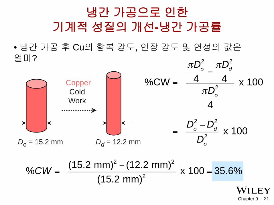
• 냉간 가공 후 Cu의 항복 강도, 인장 강도 및 연성의 값은 얼마?
냉간 가공으로 인한 기계적 성질의 개선-냉간 가공률
Do = 15.2 mm
Cold Work
Dd = 12.2 mm
Copper
21
Chapter 9 -
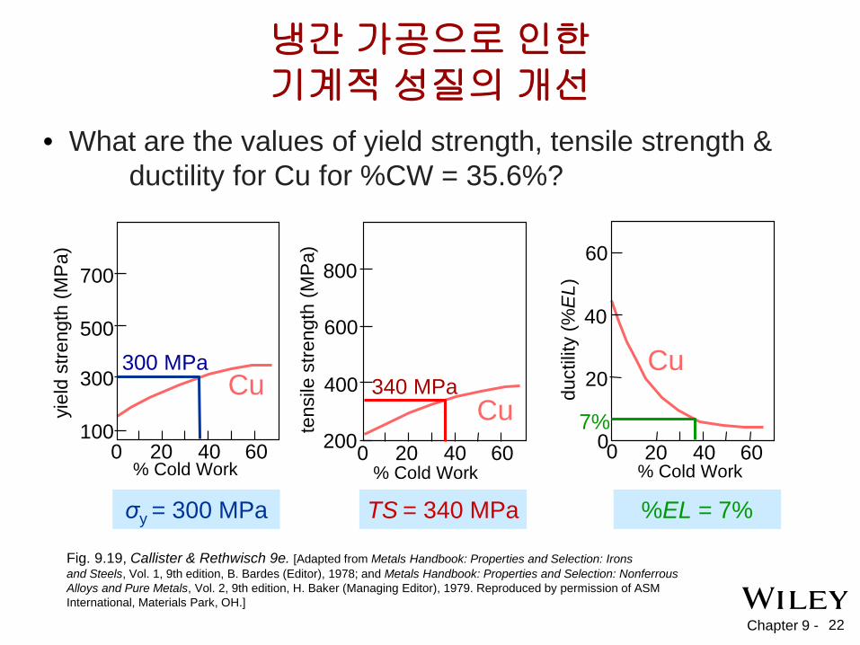
냉간 가공으로 인한 기계적 성질의 개선
% Cold Work
100
300
500
700
Cu
20 0 40 60
σy = 300 MPa
300 MPa
% Cold Work
200 Cu
0
400
600
800
20 40 60 % Cold Work
20
40
60
20 40 60 0 0
Cu 340 MPa
TS = 340 MPa
7%
%EL = 7%
• What are the values of yield strength, tensile strength & ductility for Cu for %CW = 35.6%?
yiel
d st
reng
th (M
Pa)
tens
ile s
treng
th (M
Pa)
duct
ility
(%E
L)
Fig. 9.19, Callister & Rethwisch 9e. [Adapted from Metals Handbook: Properties and Selection: Irons and Steels, Vol. 1, 9th edition, B. Bardes (Editor), 1978; and Metals Handbook: Properties and Selection: Nonferrous Alloys and Pure Metals, Vol. 2, 9th edition, H. Baker (Managing Editor), 1979. Reproduced by permission of ASM International, Materials Park, OH.]
22
Chapter 9 - 23
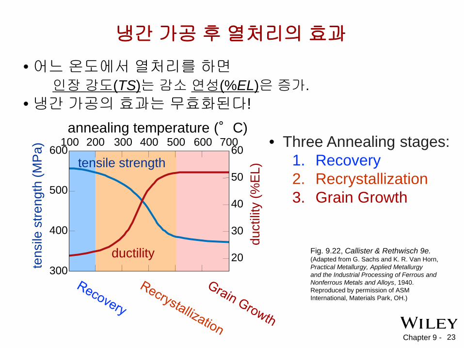
• 어느 온도에서 열처리를 하면 인장 강도(TS)는 감소 연성(%EL)은 증가. • 냉간 가공의 효과는 무효화된다!
Fig. 9.22, Callister & Rethwisch 9e. (Adapted from G. Sachs and K. R. Van Horn, Practical Metallurgy, Applied Metallurgy and the Industrial Processing of Ferrous and Nonferrous Metals and Alloys, 1940. Reproduced by permission of ASM International, Materials Park, OH.)
냉간 가공 후 열처리의 효과 te
nsile
stre
ngth
(MPa
)
duct
ility
(%EL
) tensile strength
ductility
600
300
400
500
60
50
40
30
20
annealing temperature (°C) 200 100 300 400 500 600 700 • Three Annealing stages:
1. Recovery 2. Recrystallization 3. Grain Growth

Chapter 9 - 24
Three Stages During Heat Treatment: 1. 회복 (Recovery)
• Scenario 1 원자 확산에 의해서
전위가 소멸하고 완벽한 원자면이 생성
extra half-plane of atoms
extra half-plane of atoms
원자가 인장 영역에 확산
전위가 소멸하여 밀도가 감소.
Chapter 9 - 25
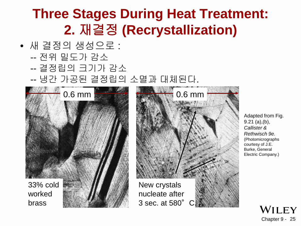
Adapted from Fig. 9.21 (a),(b), Callister & Rethwisch 9e. (Photomicrographs courtesy of J.E. Burke, General Electric Company.)
33% cold worked brass
New crystals nucleate after 3 sec. at 580°C.
0.6 mm 0.6 mm
Three Stages During Heat Treatment: 2. 재결정 (Recrystallization)
• 새 결정의 생성으로 : -- 전위 밀도가 감소 -- 결정립의 크기가 감소 -- 냉간 가공된 결정립의 소멸과 대체된다.
Chapter 9 - 26
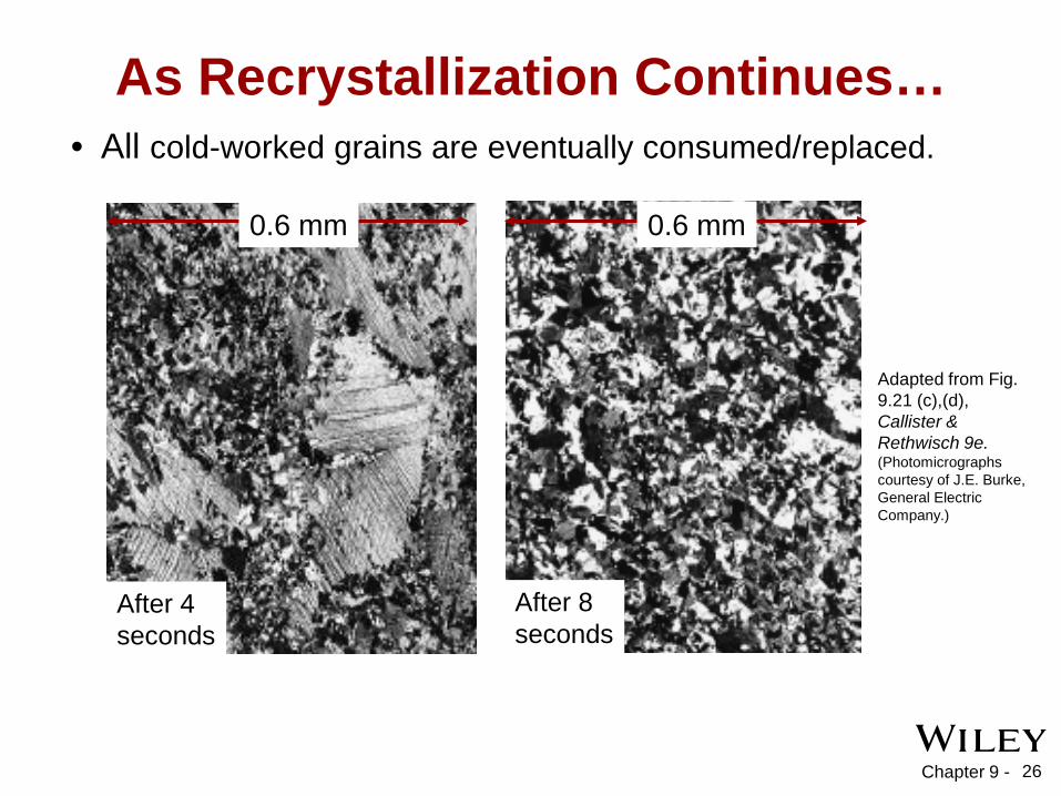
• All cold-worked grains are eventually consumed/replaced.
Adapted from Fig. 9.21 (c),(d), Callister & Rethwisch 9e. (Photomicrographs courtesy of J.E. Burke, General Electric Company.)
After 4 seconds
After 8 seconds
0.6 mm 0.6 mm
As Recrystallization Continues…
Chapter 9 - 27
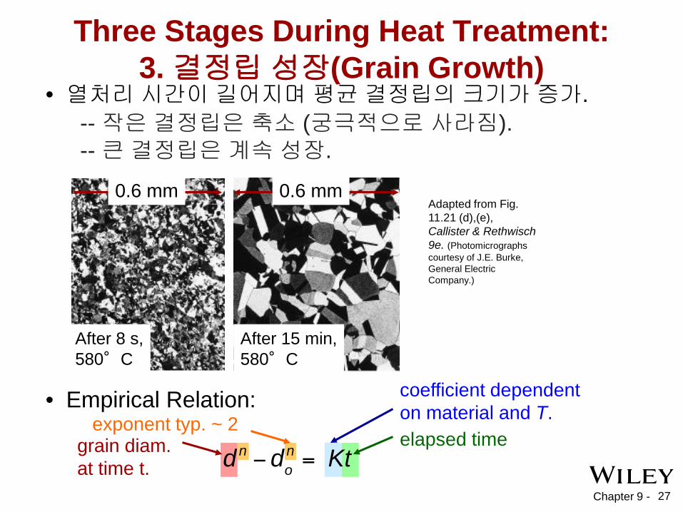
Adapted from Fig. 11.21 (d),(e), Callister & Rethwisch 9e. (Photomicrographs courtesy of J.E. Burke, General Electric Company.)
Three Stages During Heat Treatment: 3. 결정립 성장(Grain Growth)
• 열처리 시간이 길어지며 평균 결정립의 크기가 증가.
After 8 s, 580°C
After 15 min, 580°C
0.6 mm 0.6 mm
• Empirical Relation:
elapsed time
coefficient dependent on material and T.
grain diam. at time t.
exponent typ. ~ 2
-- 작은 결정립은 축소 (궁극적으로 사라짐). -- 큰 결정립은 계속 성장.

Chapter 9 - 28
TR
Fig. 9.22, Callister & Rethwisch 9e. (Adapted from G. Sachs and K. R. Van Horn, Practical Metallurgy, Applied Metallurgy and the Industrial Processing of Ferrous and Nonferrous Metals and Alloys, 1940. Reproduced by permission of ASM International, Materials Park, OH.)
TR = recrystallization temperature
재결정 온도
º
Chapter 9 - 29
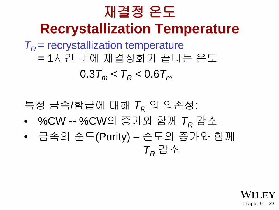
재결정 온도 Recrystallization Temperature
TR = recrystallization temperature = 1시간 내에 재결정화가 끝나는 온도
0.3Tm < TR < 0.6Tm 특정 금속/함급에 대해 TR 의 의존성: • %CW -- %CW의 증가와 함께 TR 감소 • 금속의 순도(Purity) – 순도의 증가와 함께
TR 감소
Chapter 9 - 30
Diameter Reduction Procedure - Solution
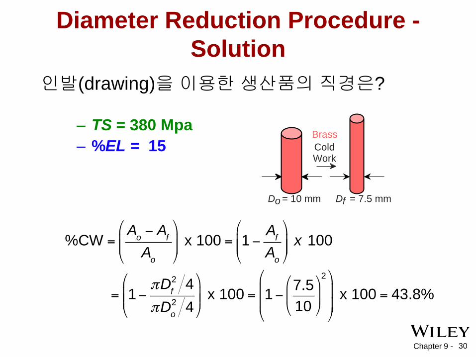
인발(drawing)을 이용한 생산품의 직경은?
D o = 10 mm
Brass Cold Work
D f = 7.5 mm
– TS = 380 Mpa – %EL = 15
Chapter 9 - 31
Diameter Reduction Procedure – Solution (Cont.)
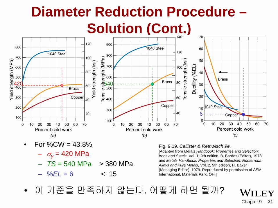
• For %CW = 43.8%
540 420
– σy = 420 MPa – TS = 540 MPa > 380 MPa
6
– %EL = 6 < 15
• 이 기준을 만족하지 않는다. 어떻게 하면 될까?
Fig. 9.19, Callister & Rethwisch 9e. [Adapted from Metals Handbook: Properties and Selection: Irons and Steels, Vol. 1, 9th edition, B. Bardes (Editor), 1978; and Metals Handbook: Properties and Selection: Nonferrous Alloys and Pure Metals, Vol. 2, 9th edition, H. Baker (Managing Editor), 1979. Reproduced by permission of ASM International, Materials Park, OH.]

Chapter 9 - 32
Diameter Reduction Procedure – Solution (cont.)
380
12
15
27
For %EL > 15 For TS > 380 MPa > 12 %CW
< 27 %CW
∴ our working range is limited to 12 < %CW < 27
Fig. 9.19, Callister & Rethwisch 9e. [Adapted from Metals Handbook: Properties and Selection: Irons and Steels, Vol. 1, 9th edition, B. Bardes (Editor), 1978; and Metals Handbook: Properties and Selection: Nonferrous Alloys and Pure Metals, Vol. 2, 9th edition, H. Baker (Managing Editor), 1979. Reproduced by permission of ASM International, Materials Park, OH.]
Chapter 9 - 33
Diameter Reduction Procedure – Solution (cont.)
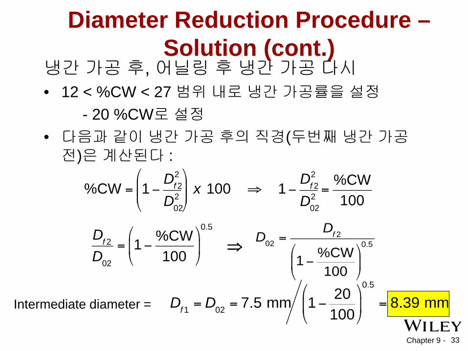
냉간 가공 후, 어닐링 후 냉간 가공 다시 • 12 < %CW < 27 범위 내로 냉간 가공률을 설정 - 20 %CW로 설정 • 다음과 같이 냉간 가공 후의 직경(두번째 냉간 가공 전)은 계산된다 :
⇒
Intermediate diameter =
Chapter 9 - 34
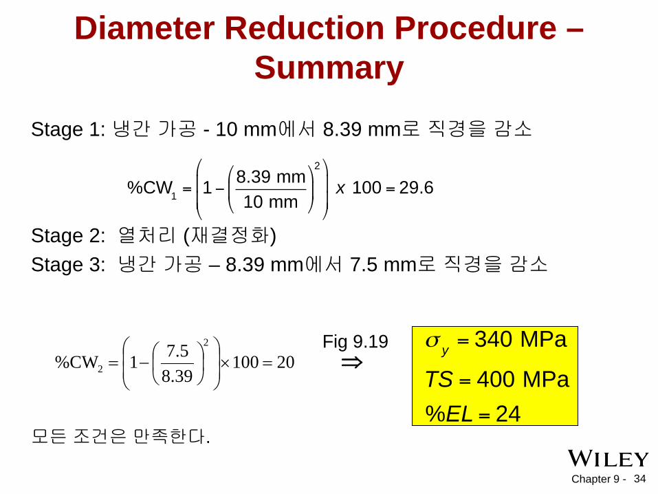
Diameter Reduction Procedure – Summary
Stage 1: 냉간 가공 - 10 mm에서 8.39 mm로 직경을 감소
Stage 2: 열처리 (재결정화) Stage 3: 냉간 가공 – 8.39 mm에서 7.5 mm로 직경을 감소
모든 조건은 만족한다.
20100 39.85.71%CW
2
2 =×
−= ⇒
Fig 9.19

Chapter 9 - 35
Cold Working vs. Hot Working
• 열간 가공 (Hot working) TR 보다 높은 온도에서 변형
• 냉간 가공 (Cold working)
TR 보다 낮은 온도에서 변형

Chapter 9 - 36
• 전위는 주로 금속 및 합금에서 발견된다.
• 전위 운동을 어렵게 만드는 것이 강도를 증가시킨다.
Summary
• 금속의 강도 증가 방법: -- 결정립 크기를 줄임 -- 고용체 강화 (solid solution strengthening) -- 냉간 가공 (cold working)
• 냉간 가공된 금속은 열처리를 통해 회복, 재결정 및 결정립 성장을 거치고 기계적 성질이 변한다.