測試高功率半導體裝置,從設計到上市面面俱到 ·...
TRANSCRIPT


2測試高功率半導體裝置,從設計到上市面面俱到
簡介
本電子指南介紹了功率半導體裝置的生命週期與各種測試和特性分析活動,並探討整個週期內各個階段所面臨的量測挑戰。從設計新功率裝置的早期階段,到產品準備上市的時間點,不論是功率裝置生命週期的哪一個階段,您都可以採用吉時利的靈活高功率特性分析工具組輕鬆進行測試。
• 對於基本的曲線追蹤量測,單一的電源量測設備 (SMU) 儀器與Android系統的曲線追蹤儀應用程序也許就已足夠。
• 需要更細緻的曲線追蹤功能時,則解決方案可能會是SMU儀器、半導體I-V特性分析軟體。
• 如需詳細的開機狀態、關閉狀態,或電容 - 電壓特性分析,則完整的參數曲線追蹤儀 (PCT) 可讓您輕鬆獲取資料並擷取詳細參數。
• 靈活的儀器不僅可用於曲線追蹤,也可以配置在機架式系統中,以進行簡單的功能測試、製程監控,或其他更高容積的特性分析。
如何在整個功率半導體裝置生命週期內進行高效又靈活的測試和特性分析
功率半導體裝置
生命週期
裝置與製程設計
生產測試
應用開發
特性分析
可靠性故障分析
用途設計
34
5
6
78
9第
頁
第
頁第
頁
第
頁
第
頁
第
頁
第
頁
Index

3
應用工程師所面對的客戶會不斷加壓、測試或伸展設計,盡可能地提高工作效率。這些客戶需要裝置規格以外的詳細資料。客戶的要求不斷地變化,所以需要量測的內容也可能會瞬息萬變。如何可以快速又輕鬆地進行量測,而不需浪費時間重新學習軟體或儀器?
吉時利提供了廣泛的測試功能,包括脈衝、直流和 C-V。ACS Basic Edition 軟體會使用裝置特定 (而非儀器特定) 的詞彙來簡化量測說明;同時這也簡化了多個電源量測設備 (SMU) 儀器之間的互動作用,因此使用者可以專注於裝置,而不是儀器。IVy Android App與系列2600B SourceMeter® SMU儀器合作以執行I-V特性分析,包括二終端和三終端裝置測試和趨勢監控, 而且無需程式設計即可啟用互動式分析並深入瞭解您的裝置!或者,使用機型 2450互動式 SourceMeter SMU儀器與 KickStart I-V 特性分析軟體,在各種材料、二終端和多終端半導體裝置、太陽能電池和嵌入式系統等設備上執行電流與電壓 (I-V)的測試。
針對新應用需求評估現有的裝置和設計
Perform these seven easy tests on your battery, diode, LED, FET, or other DUT
to identify potential issues early, avoid extensive troubleshooting, and have
confidence that the DUT is safe to use in your circuit.
I-V characterization is performed on a variety of electronic products. Typical I-V characterization requires writing programs or configuring test software to source voltage/current in a certain range, then the measured current/voltage will be displayed after you run the testing program. But, real-time control eliminates this delayed visualization that may cause you to miss some critical device behavior, providing further insight into your DUT.
You know your measurement hits a spike at a random point, but do you know how to determine the reason behind it? Measurement data makes more sense when you look at it from different perspectives.
Understand Measurement Results from Different Perspectives
A “golden device” is a “known-good” device that is often used when testing components. Compare test results of an unknown device against a standardized, known-good device to determine if it is operating correctly. Plot multiple curves on one screen, which makes comparison easier.
Compare Your Device to a “Golden Device”
1 I-V Characterization with Real-time Control
Monitor I-V Trends over Time It’s especially important to monitor device behavior over time to identify DUT problems that occur with changes in ambient conditions, such as temperature, lighting, self-heating, etc. Keithley IVy provides a time mode to monitor your devices.
2
3
7
If you’re having trouble understanding the device’s behavior, share a screenshot and the actual data with your colleagues to ensure collaborative work.
Share Measurement Results for Collaborative Work5
!uoy esirprus yam stluser tset ehT ?roivaheb esnopser-sulumits s’tnenopmoc ruoy detset uoy evaHTypically, you need to program the stimulus activities into your test program and then observe the responses. If you see some unexpected behavior after the measurement is generated, go back to the test program and try to match each stimulus with the device behavior. Ideally, you can change source value in real time to see the DUT response instantly. While you are collecting data in time mode, you can remain in control of your source by changing the source slider.
Stimulus-Response Behavior over Time
6
Is the following diode characterization normal? Zoom in to look at it more carefully before you say yes.
Zoom into Your Measurement to See the Details
4
7Keys to Detecting Potential DUT Issues Minimize Troubleshooting Time and Boost Productivity
Get the Keithley IVy Android App Now!
Use IVy with any Keithley Series 2600B SourceMeter® SMU Instrument.
Visit www.keithley.com/2600B to learn more.
The Keithley IVy AndroidTM App lets you perform these tests on your DUT with a couple of touches and just seconds of your time.
偵測潛在DUT問題的7個關鍵:減少疑難排解的時間,提高生產率
下載海報
Source Measurement Unit (SMU) Instruments Simplify Characterizing a Linear Voltage Regulator’s DC Performance October 2011 1
Linear voltage regulators (LVRs) are essen-tial elements of power management systems.
required by any electronic circuit designed
designed voltage regulator will maintain
regardless of changes in the input voltage or load current.
-tional and low dropout (LDO), function on the same principle, but an LDO LVR requires a lower input voltage in excess of the output voltage to operate than a conventional type does, thereby reducing the amount of power needed to operate it. As a result, low drop-out regulators are better suited for battery-powered electronics and portable handheld communication devices.
some common DC electrical characteris-tics of LVRs, including line regulation, load regulation, dropout voltage and quiescent
to qualifying both conventional and LDO
Testing an LVR requires a variable power source for the input side and a variable load for the output side. Source Measurement Unit (SMU) instruments are excellent candi-dates for these applications because voltage and current measurements must be made on both sides of the regulator. One SMU instrument can act as a power source on the input side; a second SMU instrument on the output side can act as a load. A growing
number of test equipment vendors have -
ments that house multiple SMU instrument channels in a single enclosure. For applica-tions like these, a dual-channel SMU instru-ment like Keithley’s Model 2602A System SourceMeter® instrument (Figure 1), could serve as an economical substitute for two separate SMU instruments.
Characterization SystemAs illustrated in Figure 2, SMU_1 is con-nected to the input side of the regulator and
-
the desired input voltage(s) applied to the
limit, is set to a value higher than the maxi-mum output current of the voltage regulator in order to account for the LVR’s current consumption.
SMU_2 is connected to the output side of the regulator. It also sources voltage and measures current (SVMI). However, the volt-
than the expected output voltage of the regu-lator. SMU_2 automatically switches to sink-ing, or drawing, current from the regulator,
-rent, or the current limit, is set to the desired load current. Given that an SMU instru-ment operates on the principles of range, it is important to ensure that SMU_2’s voltage range encompasses the expected output volt-age of the regulator to ensure the regulator output voltage is measured correctly.
LVRs may require external capacitors to ensure stable operation of the voltage
Source Measurement Unit (SMU) Instruments Simplify Characterizing a Linear Voltage Regulator’s DC PerformanceJennifer Cheney and Qing D. Starks Applications Engineering Department Keithley Instruments, Inc.
A G R E A T E R M E A S U R E O F C O N F I D E N C E
Figure 1. Series 2600A Dual-Channel System SourceMeter instruments.
閱讀文章
電源量測設備儀器可簡化線性穩壓器直流效能的特性分析工作
IVy Android App 與系列 2600B SourceMeter® SMU 儀器搭配使用以執行I-V特性分析。利用手勢捏合和縮放即可深入瞭解裝置效能
測試高功率半導體裝置,從設計到上市面面俱到
Index

4
為了有效地設計裝置,以滿足客戶的最新要求,功率裝置設計工程師和製程工程師必須瞭解如何調整製程以產生期望的裝置效能。工程是必須對裝置機型的準確度充滿信心,而且,若要變更特定的製程步驟,則必須也在裝置量測參數上進行必要的變更。因此,裝置的工程師必須執行關鍵裝置參數的初步驗證程序。
利用其追蹤模式,ACS Basic Edition軟體可讓使用者快速驗證關鍵裝置參數,包括曲線系列、偏壓等。除了具有直覺的設計,還是專門從裝置的角度設計, 包括裝置資料庫分數和內建的公式程式可迅速將量測與裝置參數建立關聯。參數曲線追蹤儀 (PCT) 配置和機型 8020 探棒台介面簡化了各種必須在晶片上執行的測試 (直流、CV和脈衝測試)。
設計全新的裝置,滿足不斷變化的需求
追蹤模式支援裝置的互動式測試。
測試現代化的功率半導體裝置需要現代化的曲線追蹤儀
觀看網路研討會
觀看線上展示
追蹤模式中的 PCT 配置
測試高功率半導體裝置,從設計到上市面面俱到
Index
5
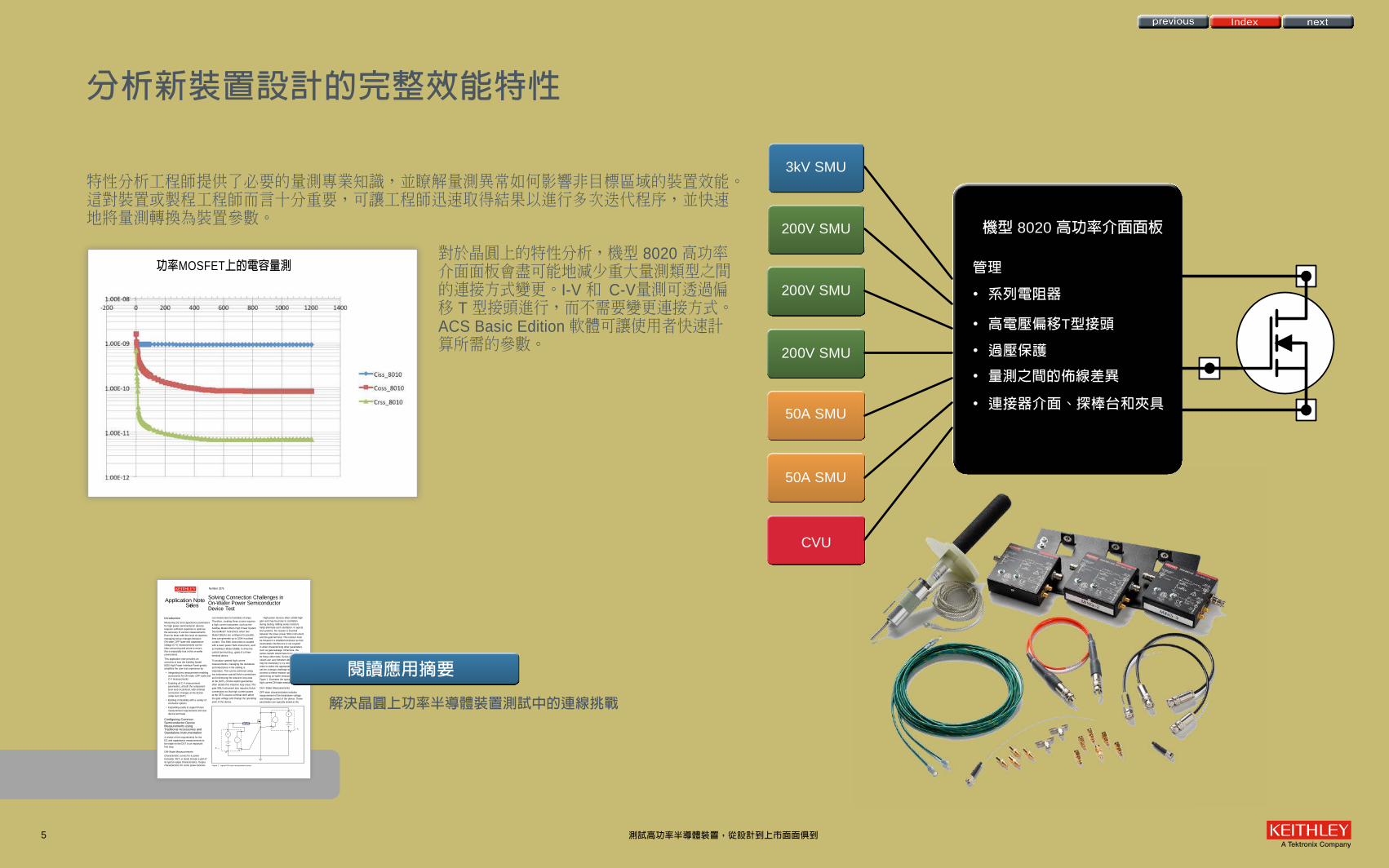
分析新裝置設計的完整效能特性
解決晶圓上功率半導體裝置測試中的連線挑戰
Solving Connection Challenges in On-Wafer Power Semiconductor Device Test
IntroductionMeasuring DC and capacitance parameters for high power semiconductor devices requires sufficient expertise to optimize the accuracy of various measurements. Even for those with this level of expertise, managing set-up changes between ON-state, OFF-state and capacitance-voltage (C-V) measurements can be time consuming and prone to errors; this is especially true in the on-wafer environment.
This application note provides an overview of how the Keithley Model 8020 High Power Interface Panel greatly simplifies the user test experience by:
• Integrating key measurement-enabling accessories for ON-state, OFF-state and C-V measurements
• Enabling all C-V measurement parameters, at both the component-level and circuit-level, with minimal connection changes at the device under test (DUT)
• Building in flexibility with a variety of connector options
• Expanding easily to support future measurement requirements and new device terminals
Configuring Common Semiconductor Device Measurements using Traditional Accessories and Standalone InstrumentationA review of the requirements for the DC and capacitance measurements to be made on the DUT is an important first step.
ON-State Measurements
Characteristic curves for a power transistor, FET, or diode include a plot of its typical output characteristics. Output characteristics for some power devices
can involve tens to hundreds of amps. Therefore, creating these curves requires a high current instrument, such as the Keithley Model 2651A High Power System SourceMeter® instrument; when two Model 2651As are configured in parallel, they can generate up to 100A in pulsed current. This SMU instrument is coupled with a lower power SMU instrument, such as Keithley’s Model 2636B, to drive the control terminal (e.g., gate) of a three-terminal device.
To produce optimal high current measurements, managing the resistance and inductance in the cabling is imperative. This can be achieved using low inductance coaxial Kelvin connections and minimizing the inductive loop area at the DUTs. (Probe station geometries often dictate this inductive loop area.) The gate SMU instrument also requires Kelvin connections so that high current pulses at the FET’s source terminal don’t affect the gate voltage and change the operating point of the device.
High power devices often exhibit high gain and may be prone to oscillation during testing. Adding series resistors helps eliminate such oscillation. In typical test systems, the resistor is inserted between the lower power SMU instrument and the gate terminal. This resistor must be housed in a shielded enclosure so that electrostatic interference is not coupled in when characterizing other parameters, such as gate leakage. Otherwise, the series resistor would have to be removed for those other tests. Series resistance values can vary between devices and it may be necessary to try several values in order to select the appropriate value. It can be a design challenge to house and connect to these resistors properly when performing on-wafer measurements. Figure 1 illustrates the typical setup for high current ON-state measurements.
OFF-State Measurements
OFF-state characterization includes measurement of the breakdown voltage and leakage current of the device. These parameters are typically tested at the
Number 3276
Application Note Se ries
fi
fl
fifl
fifl
fi
fifl
fifl
fi
Figure 1. Typical ON-state measurement setup.
閱讀應用摘要
功率MOSFET上的電容量測
特性分析工程師提供了必要的量測專業知識,並瞭解量測異常如何影響非目標區域的裝置效能。這對裝置或製程工程師而言十分重要,可讓工程師迅速取得結果以進行多次迭代程序,並快速地將量測轉換為裝置參數。
對於晶圓上的特性分析,機型 8020 高功率介面面板會盡可能地減少重大量測類型之間的連接方式變更。I-V 和 C-V量測可透過偏移 T 型接頭進行,而不需要變更連接方式。ACS Basic Edition 軟體可讓使用者快速計算所需的參數。
3kV SMU
200V SMU
200V SMU
200V SMU
50A SMU
50A SMU
CVU
管理
• 系列電阻器
• 高電壓偏移T型接頭
• 過壓保護
• 量測之間的佈線差異
• 連接器介面、探棒台和夾具
機型 8020 高功率介面面板
Index
測試高功率半導體裝置,從設計到上市面面俱到
index
6
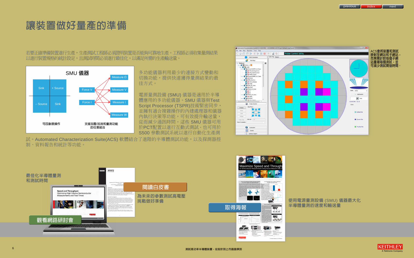
若要正確準備裝置進行生產,生產測試工程師必須證明裝置是否能夠可靠地生產。工程師必須收集量測結果以進行裝置規格的統計設定,且測試時間必須進行最佳化,以滿足所需的生產輸送量。
多功能儀器利用最少的連接方式變動和切換功能,提供快速獲得量測結果的最佳方式。
電源量測設備 (SMU) 儀器是適用於半導體應用的多功能儀器。SMU 儀器與Test Script Processor (TSPR)技術緊密同步,並擁有適合複雜操作的內建處理器和儀器內執行決策等功能,可有效提升輸送量,從而減少通訊時間。這些 SMU 儀器可用於PCT配置以進行互動式測試,也可用於S500 參數測試系統以進行自動化生產測
試。Automated Characterization Suite(ACS) 軟體結合了進階的半導體測試功能,以及探測器控制、資料報告和統計等功能。
讓裝置做好量產的準備
ACS會將裝置和測試映射至網站和子網站,而無需針對每個子網站重複每個測試,並可減少測試開發時間。
使用電源量測設備 (SMU) 儀器最大化半導體量測的速度和輸送量
為未來的參數測試高電壓挑戰做好準備
SMU 儀器
可四象限操作 支援加壓/加流和量測功能 的任意組合
+ Source Force V
Force I
Measure V
Measure I
Measure Ω
Measure W
Sink
Sink– Source
Maximize Speed and Throughput for Semiconductor Measurements Using Source Measure Units (SMUs)
Use a Four-Quadrant SMU Instrument Instead of a Power Supply and Digital Multimeter
Use Embedded Test Scripts to Minimize Program Execution Time
Test in Parallel with Distributed Control Use Triax Cabling Instead of Coax Cabling
Many semiconductor and electronic device tests involve sourcing a voltage and measuring a current as quickly as possible. Overall test time is a function of charge time, measure time, and discharge time, as well as the time to setup and process the test.Traditional power supplies can only source voltage or current and cannot sink. But, a four-quadrant SMU instrument can source and sink both voltage and current, while simultaneously measuring voltage, current, or resistance. The SMU instrument’s four-quadrant operation speeds up the discharge time by automatically using sink mode to quickly absorb all the charge from the device under test (DUT) and cabling. In additon, by tightly integrating this source and measure capability into one instrument, the need for a separate digital multimeter (DMM) and power supply is eliminated. This improves test times, simplifies overall test system design, and increases usability.
When a typical test program executes from a PC controller, it continually communicates back and forth with the test instru-mentation. This communication time, whether it is over GPIB, LAN, USB, or some other proto-col, is often one of the largest contributors to slower test times.Embedded test scripts minimize this communication time by storing and then executing entire test programs directly from the instrument’s non-volatile memory. All setup, decision-making, and data storage is now done from inside the instrument itself, independent of the PC. By using embedded test scripts, Keithley’s Test Script Processor (TSP®) technology enables dramatic improvements in overall test throughput. For example, a typical three-point diode test runs over 60% faster using embedded test scripts compared to traditional programming techniques.
Implementing parallel test techniques to test multiple devices at the same time maximizes parts tested per prober touch-down or handler index, thus boosting productivity and lowering the cost of test. In a traditional test system, only one instrument at a time can execute a measurement or communicate with the PC controller. All other instruments in the system sit idle until it is their turn to communicate with the PC controller.In a distributed test system, the embedded test script (TSP script) is distributed and synchronized across multiple instruments through TSP-Link® technology, a high-speed, SMU-to-SMU communication bus. There is one CPU per SMU instrument, and each SMU instrument works together as a coordinated system. Through the combination of TSP and TSP-Link technologies, measurements are performed in parallel.
The coax cable’s signal to lo resistance causes a par-allel current path that slows down settling times and limits the low current resolution of the system.
The extra shield in the triax cable works with the driven guard in the SMU instrument to virtually eliminate the parallel current path. This enables faster settling times and better measurement resolution.
4 Quadrant SMU
Using a Model 2657ATime Scale = 2 msec/div
Total discharge time ~ 5 msec
Using a Power SupplyTime Scale = 2 sec/div
Total discharge time > 6 sec
SOURCING VOLTAGE MEASURING CURRENT
2 Quadrant Power Supply
TRADITIONAL TEST SYSTEMS
DISTRIBUTED TEST SYSTEMS
Production Test Die Sort | Wafer Acceptance Test | Reliability | Package Part Extreme Measurements | Higher Breakdown Voltage | Lower Leakage Current | Lower On Resistance | Higher PowerExtreme Measurements | Higher Breakdown Voltage | Lower Leakage Current | Lower On Resistance | Higher Power New Processes/New Materials SiC | GaN | Other…
A Greater Measure of Confidence
Diode Test
Without Scripting
80
60
40
20
0
Avg
. tim
e pe
r pa
rt (
ms)
With Scripting
Vf test
I
V
VR test
2600B System SourceMeter® SMU Instrumentsn Dual- or single-channel modelsn Test up to 200V and 10A pulsen Sub-pA resolutionn TSP and TSP-Link technologies
2400 SourceMeter® SMU Instrumentsn Test up to 1100V and 10A pulsen Choose from over ten modelsn pA resolutionn Entry-level price point
2650A High Power System SourceMeter® SMU Instrumentsn Test up to 3kV and 100A pulse with 200W
output powern 1µsec/point digitizern Sub-pA resolutionn TSP and TSP-Link technologies
2450 Advanced Touchscreen SourceMeter® SMU Instrument n Industry-first 5-inch color
capacitive touchscreen GUIn Test up to 200V and 1An Sub-pA resolutionn TSP and TSP-Link technologies
© Copyright 2013 Keithley Instruments, Inc. Printed in the U.S.A. No. 3246 02.14
Triax cables enable faster settling times and better resolution when sourcing or measuring.
1
Keithley Instruments, Inc.28775 Aurora RoadCleveland, Ohio 44139(440) 248-0400Fax: (440) 248-6168www.keithley.com
Gearing Up for Parametric Test’s High Voltage Future
Paul Meyer Product Marketer–Business Development Department
Keithley Instruments, Inc.
IntroductionMany parametric test engineers are learning to cope with new high voltage process requirements. Not surprisingly, high voltage processes require high voltage parametric testing for process control and reliability monitoring. Part of the challenge lies in the fact that these new high voltage requirements add to the list of parametric tests rather than replacing some portion of it. In many if not most cases, the high voltage transistors are controlled by complex logic that requires low voltage/low current parametric test. Consequently, both high voltage and logic tests have to be addressed within the same test plan while minimizing impact on throughput.
How Did This Happen?The IC industry has been delivering on Gordon Moore’s prediction of doubling transistor density every 18 months and has done so for nearly half a century. As computing power soared, the need to integrate more of the product functionality into a single chip has led to concepts like “More than Moore.” Whereas Moore referred to transistor density scaling, “More than Moore” speaks to scaling the circuit board down to a single chip. The power devices that once lived on the circuit board are increasingly integral to the IC itself.
One of the first areas to benefit from the “More than Moore” philosophy is power management. Power management comes in several flavors, including smart power management, green power management, and integrated power management. In every case, the combination of computational power, programmability, and high power driver circuits provide a platform to control and manage power and, consequently, to exercise control over the real world.
For example, let’s consider Bipolar-CMOS-DMOS (BCD) technology. The term BCD is often used to describe a number of variants, including combinations such as
觀看網路研討會
閱讀白皮書
取得海報
最佳化半導體量測和測試時間
測試高功率半導體裝置,從設計到上市面面俱到

index
7
若要確保裝置符合商業用途的可靠性標準,可靠性測試工程師需負責:
• 確定裝置是否能克服環境壓力,並能持續符合規格
• 回答客戶對裝置使用壽命所提出的問題 (MTBF、MTTF)
• 針對某些高可靠性的應用 (軍事/航空、汽車等) 為裝置提供了關鍵的詳細資料。
建立相關統計結果需要有足夠的測試裝置取樣量。若要在許多裝置上執行加壓量測循環,則必須具備多通道並列測試與自動化資料評估功能。
S500整合測試系統是可靠性測試系統,使用者可自訂以適應各種數量的裝置。ACS提供加壓量測迴路循環及整合式決策功能。吉時利還提供了各種電源供應器和SMU儀器解決方案,以允許同時進行任何數量裝置的電源和測試作業。
符合商業用途的可靠性標準
HCI/NBTI/恆流EM測試的處理流程。
利用吉時利SMU儀器和切換系統最佳化功率半導體裝置和模組的可靠性測試 DS
使用Automated Characterization Suite (ACS) 軟體進行高功率半導體裝置的V 斜波和HTRB可靠性測試
高電壓半導體裝置的擊穿和漏電流量測
1
application brief
Optimizing Reliability Testing of Power Semiconductor Devices and Modules with Keithley SMU Instruments and Switch SystemsIntroductionTo minimize early defect rates and to continuously improve the overall reliability and lifetime of power semiconductors, a variety of important tests are performed by both manufacturers and end-use designers. Many of these tests are outlined in JEDEC Standards such as JESD22-A108D “Temperature, Bias, and Operating Life,” JESD22-A110D “Highly Accelerated Temperature and Humidity Stress Test (HAST),” or JESD236 “Reliability Qualification of Power Amplifier Modules.” This application brief discusses methods to optimize reliability testing of silicon and wide band gap (WBG) power semiconductor devices, modules, and materials by using Keithley SourceMeter® Source Measure Unit (SMU) Instruments and Switch Systems (Figures 1 and 2 ).
Typical Reliability TestsTypical reliability tests involve stressing a batch or batches of sample devices for hundreds or thousands of hours with bias voltages that are greater than or equal to their normal operating voltages while subjecting them to temperatures that are well beyond normal operating conditions. During this stress, a variety of key operating parameters are measured at specific time intervals. Some of the more popular reliability tests for power semiconductors are HTOL (High Temperature Operating Life), ELFR (Early Life Failure Rate), HTFB (High Temperature Forward Bias), HTRB (High Temperature Reverse Bias), and HAST (Highly Accelerated Temperature & Humidity Stress Test). These tests will either use a continuous bias (Figure 3 ) or cycled bias (Figure 4 ). A continuous bias can be a fixed voltage or a staircase ramp. A cycled bias will typically vary the duty cycle and/or frequency of the bias voltage. In both cases, key device parameters will be tested continuously or at specific time intervals.
Reliability Testing ChallengesReliability testing of today’s WBG power semiconductors presents several key challenges for engineers and test system designers. Most importantly, since most of these devices are being targeted for energy-efficiency applications, they have much lower leakage and on-resistance specifications compared to traditional silicon. The test instrumentation must therefore be capable of providing the necessary accuracy, resolution, and stability to meet the electrical requirements of these devices. In addition, since WBG devices exhibit failure mechanisms that are different from silicon, effective reliability testing per JEDEC standards requires larger sample sizes and longer stress durations to adequately predict important reliability parameters. This requires test instrumentation that is capable of supplying enough power to test many devices in parallel, while maintaining the accuracy and resolution mentioned above. Finally, the test instrumentation must be able to respond to the high speed behaviors associated with these devices and produce the masses of data associated with testing devices in parallel. Each instrument in the system must be fast, and all units must operate in a highly synchronized manner.
Figure 1. Keithley Series 2650A High Power SourceMeter SMU Instruments.
Figure 2. Keithley Series 3700A and 707B Series Switch Systems.
VDS Ramp and HTRB Reliability Testing of High Power Semiconductor Devices with Automated Characterization Suite (ACS) Software
IntroductionWide bandgap semiconductor materials such as silicon carbide (SiC) and gallium nitride (GaN) offer physical properties superior to those of silicon (Si) for power device applications, enabling devices based on these materials to withstand high voltages and temperatures, as well as permitting higher frequency response, greater current density, and faster switching [1]. These emerging power devices have great potential; however, the technologies necessary to create and refine them are still under development and therefore less mature than silicon technology. This creates some big challenges associated with designing and characterizing these devices, as well as process monitoring and reliability issues [2].
Before they can gain commercial acceptance, the reliability of wide bandgap devices must be proven and there is a demand for higher reliability requirements. The continuous drive for greater power density at the device and package levels creates consequences in terms of higher temperatures and temperature gradients across the package. New application areas often mean more severe ambient conditions. For example, in automotive hybrid traction systems, the cooling liquid for the combustion engine may reach temperatures as high as 120°C. In order to provide sufficient margin, this means the maximum junction temperature (T JMAX) must be increased from 150°C to 175°C [4]. In safety-critical applications such as aircraft, the zero-defect concept has been proposed to meet stricter reliability requirements.
VDS Ramp and HTRB Reliability TestsThe VDS ramp and the High Temperature Reverse Bias (HTRB) tests are among the most common reliability tests for power devices. In a VDS ramp test, as the drain-source voltage is stepped from a low voltage to a voltage that’s higher than the rated maximum drain-source voltage, specified device parameters are evaluated. The test is useful for tuning the design and process conditions, as well as verifying that devices deliver the performance specified on their data sheets. For example, Dynamic RDS(ON), monitored using a VDS ramp test, provides a measurement of how much a device’s ON-resistance increases after being subjected to a drain bias [5]. Although a VDS ramp test is generally used as a quick form of parametric verification, an HTRB test evaluates long-term stability under high drain-source bias. During an HTRB test, the device samples are stressed at or slightly less than the maximum rated reverse breakdown voltage (usually 100% or 80% of VRRM) at an ambient temperature close to their maximum rated junction temperature (T JMAX) over a
period of time (usually 1,000 hours)[3][5][6][7]. The leakage current is continuously monitored throughout the test and a fairly constant leakage current is generally required to pass the test. Because it combines electrical and thermal stress, this test can be used to check the junction integrity, crystal defects and ionic-contamination level, which can reveal weaknesses or degradation effects in the field depletion structures at the device edges and in the passivation [8].
Test Instrumentation and Measurement ConsiderationsPower device characterization and reliability testing require test instrumentation with higher voltage as well as more sensitive current measurement capability than ever before [2]. During operation, the devices undergo both electrical and thermal stress: when in the ON state, they have to pass tens or hundreds of amps with minimal loss (low voltage, high current); when they are OFF, they have to block thousands of volts with minimal leakage currents (high voltage, low current). Additionally, during the switching transient, they are subjected to a brief period of both high voltage and high current. The high current experienced during the ON state generates a large amount of heat, which may degrade device reliability if it is not dissipated efficiently [1].
Reliability tests typically involve high voltages, long test times, and often multiple devices under test (wafer level testing). As a result, well-designed test systems and measurement plans are essential to avoid breaking devices, damaging equipment, and losing test data. Consider the following factors when executing VDS ramp and HTRB reliability tests:
Number 3220
Application Note Se ries
A Tektronix Company
Figure 1. Automated Characterization Suite (ACS) graphical user interface
Breakdown and Leakage Current Measurements on High Voltage Semiconductor Devices Using Keithley Series 2290 High Voltage Power Supplies and Series 2600B System SourceMeter ® Source Measure Unit (SMU) Instruments
Increased attention to energy efficiency has resulted in electronics with higher power density. In grid-connected and industrial applications, such as AC motor control, uninterruptible power supplies (UPS,) and traction control (large hybrid and electric transport vehicles,) the need to keep manageable cable sizes pushes power conversion to higher voltages. For such voltages, the semiconductor device of choice has historically been the thyristor. Technological advances in device fabrication and material processing is enabling the development of IGBTs and MOSFETs with voltage ratings of thousands of volts. In applications where possible, using IGBTs or even MOSFETs in place of thyristors permits power conversion at high switching frequencies. The migration to higher frequency reduces the size of passive components used in the design and, thereby, improves energy efficiency.
Keithley has long had a strong presence in high power semiconductor device test with its high voltage source-measure products, including the Models 237, 2410, and 2657A SMU instruments. Most recently, Keithley released the Model 2290-5 5kV and Model 2290-10 10kV High Voltage Power Supplies. This note considers the application of these power supplies to high voltage semiconductor device testing.
High Voltage Device TestsBasic characterization of high voltage semiconductor devices typically involves a study of the breakdown voltage and leakage current. These two parameters help the device designer to quickly determine whether the device was correctly manufactured and whether it can be effectively used in the target application.
Breakdown Voltage Measurements
Measuring breakdown voltage is done by applying an increasing reverse voltage to the device until a certain test current is reached that indicates that the device is in breakdown. Figure 1 depicts a breakdown measurement on a high voltage diode using a Series 2290 High Voltage Power Supply. Note that the Series 2290 Power Supplies are unipolar supplies and must be connected to the diode’s cathode in order to apply a reverse voltage.
In qualifying breakdown voltage, measurements are typically made well beyond the expected rating of the device to ensure that the device is robust and reliable. The models 2290-5 and 2290-10 Power Supplies have a voltage range wide enough to test many of the industry’s future devices.
Safety Considerations
When testing at high voltage, safety is of utmost concern. The Series 2290 Power Supplies generate voltage up to 10kV, so precautions must be taken to ensure that the operator is not exposed to unsafe voltage:
• Enclose the device under test (DUT) and any exposed connections in a properly grounded fixture.
• Use the safety interlock. The Series 2290 Power Supplies are fully interlocked so that the high voltage output is turned off if the interlock is not engaged (interlock switch closed.) The interlock circuit of the power supply should be connected to a normally-open switch that closes only when the user access point in the system is closed to ensure that operators cannot come in contact with a high voltage connection to the DUT. For example, opening the lid of the test fixture should open the switch/relay that disengages the interlock of the Series 2290 Power Supply.
• Use cables and connectors rated to the maximum voltage in the system. Series 2290 Power Supplies provide a number of appropriately-rated accessories that the test system designer can use to interface to the device under test (DUT).
Leakage Current Measurements
In a typical power conversion application, the semiconductor device is used as a switch. Leakage current measurements indicate how closely the semiconductor performs to an ideal switch. Also, when measuring the reliability of the device,
Number 3249
Application Note Se ries
Series 2290High VoltagePower Supply
Properly groundedsafe enclosure
A
Figure 1. Typical breakdown voltage measurement of a high voltage diode using the Series 2290 High Voltage Power Supply.
深入瞭解這些應用資源
預加壓特性分析
記錄資料
記錄資料
中期量測
增加加壓時間
加壓
是
是
否
否
停止
失敗?
失敗/結束?
失敗?
測試高功率半導體裝置,從設計到上市面面俱到

index
8
一旦裝置驗證後,即已準備好用於商業用途。購買裝置的使用者必須驗證裝置是在特定應用的容錯範圍內,以確保終端產品能達到預期的功率效率提升。隨著裝置的成熟且有多個供應商可提供相關產品,電源裝置的消費者會想要快速檢查所引入的裝置,識別並消除偽劣的裝置,以避免在終端產品中存在潛在的故障。
Tektronix 和吉時利提供各種各樣的電源供應器解決方案,為基本的電路板供電。此外,Tektronix的電源分析儀可以快速又準確地評估整體終端產品效能。吉時利參數曲線追蹤儀 (PCT) 的配置和ACS Basic Edition 軟體包括大量的電力裝置測試,讓使用者可快速驗證個別的裝置效能。 示波器搭配選配的電源分析模組即可快速又準確地分析切換損耗、諧波、安全操作區。使用者可選擇各種高電壓、電流和差動式探棒,以與示波器搭配使用。
以實際的設計實作裝置
利用吉時利高功率系統 SourceMeter® SMU 儀器測試功率半導體裝置
使用系列 2600B 和系列2650A 系統SourceMeter® SMU 儀器的任意波形功能來執行 Ford EMC-CS-2009.1 CI 230 電源循環測試
1
Testing Power Semiconductor Devices with Keithley High Power System SourceMeter ® SMU Instruments
IntroductionThe proliferation of electronic control and electronic power conversion into a variety of industries (e.g., energy generation, industrial motor drives and control, transportation, and IT) has spurred growth in power semiconductor device design and test. To demonstrate technology improvements, new device capabilities must be compared with those of existing devices. The use of semiconductor materials other than silicon demands the use of new processes. And, to be sustainable, these new processes must be tuned to deliver consistent results and high production yield. As new device designs are developed, reliability measurements are performed on many devices over long periods. Therefore, test engineers must identify test equipment that is not only accurate but scalable and cost-effective.
Power module design engineers—the consumers of the discrete power semiconductor components—work at the other end of the semiconductor device testing spectrum. They integrate the discrete components into designs for DC-DC converters, inverters, LED controllers, battery management chips, and many other devices. Driven by demands for higher energy efficiency, these engineers need to qualify the devices they receive from their vendors to ensure that they can withstand use in the application, predict how the efficiency of the power modules may be affected by the device, and finally validate the performance of the end product.
Keithley’s SourceMeter SMU instruments give both device test engineers and power module design engineers the tools they need to make the measurements they require. Whether they’re familiar with curve tracers, semiconductor parameter analyzers, or oscilloscopes, they can obtain accurate results simply and quickly. This application note highlights some of the most commonly performed tests, the challenges associated with them, and how Keithley SMU instruments can simplify the testing process, especially when integrated into a Keithley Parametric Curve Tracer (PCT) configuration.
Background on Power Device CharacterizationThe switching power supply is one common electrical circuit element used in power management products. In its simplest form ( Figure 1 ), its main components include a semiconductor such as a power MOSFET, a diode, and some passive components, including an inductor and a capacitor. Many also include a transformer for electrical isolation between the input and output. The semiconductor switch and diode alternatively
switch on and off at a controlled duty cycle to produce the desired output voltage.
When evaluating energy efficiency, it’s important to understand the switching loss (energy loss that occurs during the short periods when the device is changing states) and conduction loss (energy losses that occur when the device is either on or off). Keithley SMU instrument-based solutions can help test engineers evaluate the device parameters that affect conduction loss.
Semiconductor devices are often used to ensure circuit protection. For example, some thyristor devices are used for overvoltage protection. To achieve that objective, such devices must trigger at the appropriate intended voltage and current, must withstand the intended voltage, and must behave in circuit with minimal current draw. High power instrumentation is required to qualify these devices properly.
This note focusses on the characterization of static power device parameters.1 These parameters can be divided into two broad categories: those that determine the performance of the device in its ON state and those that determine the performance in its OFF state. Table 1 lists common ON-state and OFF-state parameters for several power semiconductor devices that Keithley SMU instruments support. Many tests involve the use of multiple SMU instruments. Keithley’s ACS Basic Edition software simplifies the test configuration by managing the configuration and data collection of all SMU instruments in the test system. Unlike general-purpose start-up software, ACS Basic Edition is designed specifically for semiconductor device characterization and includes a library of tests; users can focus on the test and device parameters rather than the SMU instrument configuration.
1 Tektronix solutions are available for transient characterization of power devices. For more information, visit www.tek.com.
Number 3204
Application Note Se ries
A Tektronix Company
VIN VOUT
Figure 1. A simple schematic of a type of switching power supply.
Using the Arbitrary Waveform Capabilities of the Series 2600B and Series 2650A System SourceMeter ® SMU Instruments to Perform Ford EMC-CS-2009.1 CI 230 Power Cycling Testing
Introduction
Arbitrary waveform generators are very flexible instruments capable of outputting voltage waveforms of virtually any shape. These instruments are quite useful because they provide a controlled method of recreating the varying signals that may be seen by a device after it is placed into a system. By recreating these signals, device designers can use them to test their devices. Unfortunately, arbitrary waveform generators typically cannot supply very much current and max out at just a few hundred milliamps. For many devices, this level of current is simply insufficient. To achieve higher currents, the arbitrary waveform generator can be combined with a power amplifier, but this requirement for additional hardware not only adds cost but increases the complexity of the test system. A much better solution would be a single box that can output both an arbitrary waveform and the additional current required by the device. One such instrument is the Source Measure Unit (SMU) instrument.
SMU instruments combine the capabilities of a precision DC power supply with the measurement capabilities of a highly accurate DMM. These instruments are most commonly used when a very precise current or voltage must be sourced and an accurate voltage or current measurement must be made. These instruments are used to characterize devices by sweeping voltage or current across the device and measuring the corresponding current or voltage. Because performing sweeps is so common, most of these instruments have sweep capabilities built right in, allowing the user to program the instrument to perform linear, logarithmic or list sweeps easily with a minimal number of commands. Although the linear sweep is certainly the most common type, the real power lies with the list sweep. In a list sweep, the user provides the value of every point in the sweep. This sweep type allows the SMU instrument to be used as an arbitrary waveform generator.
One test that requires arbitrary waveform capability but requires more current than an arbitrary waveform generator can provide is the CI 230 Power Cycling test as specified by the Ford EMC-CS-2009.1 specification. This test simulates the changes in supply voltage seen by the electrical and/or electronic components and subsystems of the automobile when the engine is being started. It specifies the use of four different waveforms, each being quite complex and including DC levels, step functions, ramp functions, and a 4Hz sine wave. The specifications for these waveforms can be seen in Figure 1 .
The automobile components and subsystems tested often require several amps of current in order to function properly.
With arbitrary waveform capabilities and the ability to source up to 20A of DC current, SMU instruments are very capable for performing this test. This application note shows how to use Keithley Series 2600B and Series 2650A System SourceMeter SMU Instruments as arbitrary waveform generators to generate these complex waveforms.
Configuring the SMU for AWG Output
Configuring the Series 2600B and Series 2650A System SourceMeter SMU Instruments for arbitrary waveform output is very similar to configuring them for any normal list sweep. The major difference is that for arbitrary waveform output, a
constant update rate is necessary for the source output, so some additional timing control is required. To set up the SMU instruments for arbitrary waveform output, take the following steps:
Number 3248
Application Note Se ries
Figure 1: Ford EMC-CS-2009.1 CI 230 power cycling waveforms
取得應用摘要
深入瞭解
測試高功率半導體裝置,從設計到上市面面俱到

index
9 測試高功率半導體裝置,從設計到上市面面俱到
故障分析工程師必須確定故障到底是由終端產品的使用或是以前忽視的設計缺陷所造成。一旦確定,設計和製程工程必須找出故障的原因,以進行製程或設計的變更,防止日後再度發生故障。
重要的是,基本裝置規格 (靜態和動態) 可以迅速地進行量測。工程師需模仿終端使用應用以盡力重現故障狀況。
參數曲線追蹤儀配置具備追蹤模式,提供了快速的裝置分析功能。此外,吉時利 Auto-mated Characterization Suite (ACS) 具有數種內建的加壓量測測試,可用於讓裝置達到期望的退化等級。
診斷裝置故障
DS
使用Automated Characterization Suite (ACS) 軟體進行高功率半導體裝置的V 斜波和 HTRB可靠性測試
使用V 斜波和J 斜波技術評估氧化物可靠性
使用機型2460量測具有高電流的低電阻裝置
使用吉時利機型4200-SCS監測MOSFET裝置的通道熱載波 (CHC) 退化
VDS Ramp and HTRB Reliability Testing of High Power Semiconductor Devices with Automated Characterization Suite (ACS) Software
IntroductionWide bandgap semiconductor materials such as silicon carbide (SiC) and gallium nitride (GaN) offer physical properties superior to those of silicon (Si) for power device applications, enabling devices based on these materials to withstand high voltages and temperatures, as well as permitting higher frequency response, greater current density, and faster switching [1]. These emerging power devices have great potential; however, the technologies necessary to create and refine them are still under development and therefore less mature than silicon technology. This creates some big challenges associated with designing and characterizing these devices, as well as process monitoring and reliability issues [2].
Before they can gain commercial acceptance, the reliability of wide bandgap devices must be proven and there is a demand for higher reliability requirements. The continuous drive for greater power density at the device and package levels creates consequences in terms of higher temperatures and temperature gradients across the package. New application areas often mean more severe ambient conditions. For example, in automotive hybrid traction systems, the cooling liquid for the combustion engine may reach temperatures as high as 120°C. In order to provide sufficient margin, this means the maximum junction temperature (T JMAX) must be increased from 150°C to 175°C [4]. In safety-critical applications such as aircraft, the zero-defect concept has been proposed to meet stricter reliability requirements.
VDS Ramp and HTRB Reliability TestsThe VDS ramp and the High Temperature Reverse Bias (HTRB) tests are among the most common reliability tests for power devices. In a VDS ramp test, as the drain-source voltage is stepped from a low voltage to a voltage that’s higher than the rated maximum drain-source voltage, specified device parameters are evaluated. The test is useful for tuning the design and process conditions, as well as verifying that devices deliver the performance specified on their data sheets. For example, Dynamic RDS(ON), monitored using a VDS ramp test, provides a measurement of how much a device’s ON-resistance increases after being subjected to a drain bias [5]. Although a VDS ramp test is generally used as a quick form of parametric verification, an HTRB test evaluates long-term stability under high drain-source bias. During an HTRB test, the device samples are stressed at or slightly less than the maximum rated reverse breakdown voltage (usually 100% or 80% of VRRM) at an ambient temperature close to their maximum rated junction temperature (T JMAX) over a
period of time (usually 1,000 hours)[3][5][6][7]. The leakage current is continuously monitored throughout the test and a fairly constant leakage current is generally required to pass the test. Because it combines electrical and thermal stress, this test can be used to check the junction integrity, crystal defects and ionic-contamination level, which can reveal weaknesses or degradation effects in the field depletion structures at the device edges and in the passivation [8].
Test Instrumentation and Measurement ConsiderationsPower device characterization and reliability testing require test instrumentation with higher voltage as well as more sensitive current measurement capability than ever before [2]. During operation, the devices undergo both electrical and thermal stress: when in the ON state, they have to pass tens or hundreds of amps with minimal loss (low voltage, high current); when they are OFF, they have to block thousands of volts with minimal leakage currents (high voltage, low current). Additionally, during the switching transient, they are subjected to a brief period of both high voltage and high current. The high current experienced during the ON state generates a large amount of heat, which may degrade device reliability if it is not dissipated efficiently [1].
Reliability tests typically involve high voltages, long test times, and often multiple devices under test (wafer level testing). As a result, well-designed test systems and measurement plans are essential to avoid breaking devices, damaging equipment, and losing test data. Consider the following factors when executing VDS ramp and HTRB reliability tests:
Number 3220
Application Note Se ries
A Tektronix Company
Figure 1. Automated Characterization Suite (ACS) graphical user interface
Measuring Low Resistance Devices with High Current Using the Model 2460 SourceMeter ® SMU Instrument
IntroductionLow resistance measurements offer a good way to identify resistance elements that have changed over time. Often, these types of measurements are used to evaluate if a device or material has degraded due to environmental factors like heat, fatigue, corrosion, vibration, etc. For many applications, these measurements are typically lower than 10Ω. A change in resistance value is often the best indicator of some form of degradation between two points of contact. Low resistance measurements performed using high currents are commonly used to evaluate high power resistors, circuit breakers, switches, bus bars, cables and connectors, and other resistance elements.
Most digital multimeters (DMMs) lack the ability to make low resistance measurements with high currents. A DMM combined with a power supply will work, but these instruments must first be integrated into a system in order to automate the measurement process, then the resistance must be calculated manually.
Source Measure Unit (SMU) instruments or SourceMeter® instruments can simplify making low resistance measurements with high current stimulus. A SourceMeter instrument is capable of sourcing and measuring both current and voltage. Keithley’s Model 2460 High Current SourceMeter SMU Instrument has the flexibility to source/sink high current and measure voltage and current, making it a perfect solution for measuring low resistance devices that require stimulus currents up to 7A. The Model 2460 automatically calculates the resistance, so there’s no need to make the calculation manually. Built-in features such as remote sensing and offset compensation help optimize low resistance measurements. The Model 2460 offers <1mΩ resolution.
Low resistance measurements can be made using either the Model 2460’s front-panel or rear-panel terminals, as shown in Figures 1 and 2. Note that either the front-panel terminals or rear-panel terminals must be used—the connections can’t be mixed.
When the leads are connected to the device under test (DUT), note that the FORCE LO and SENSE LO connections are attached to one of the DUT leads and the FORCE HI and SENSE HI connections are attached to the other lead. The sense connections should be connected as close to the resistor under
test as possible. This four-wire measurement cancels out the resistance of the test leads in the measurement.
Figure 1 illustrates the front-panel connections, which can be made with four insulated banana cables that are rated to the maximum current (7A), such as two sets of Keithley’s Model 8608 High-Performance Clip Lead Set.
Figure 1. Model 2460 front-panel connections for low resistance measurements
Figure 2 illustrates the rear-panel connections, which can be made with either the Model 2460-KIT Screw-Terminal Connector Kit (included with the Model 2460) or a Model 2460-BAN Banana Test Leads/Adapter Cable with appropriate cabling.
Figure 2. Model 2460 low resistance connections on rear panel
Common sources of error for low resistance measurementsLow resistance measurements are subject to errors from a variety of sources, including lead resistance, non-ohmic contacts, and device heating.
Number 3282
Application Note Se ries
Number 2240
Evaluating Oxide Reliability Using V-Ramp and J-Ramp Techniques
IntroductionOxide integrity is an important reliability concern, especially fortoday’s ULSI MOSFET devices, where oxide thickness has beenscaled to a few atomic layers. The JEDEC 35 Standard(EIA/JESD35, Procedure for Wafer-Level Testing of ThinDielectrics) describes two wafer level test techniques commonlyused to monitor oxide integrity: voltage ramp (V-Ramp) and cur-rent ramp (J-Ramp). Both techniques provide fast feedback foroxide evaluation.
The instrumentation used to monitor oxide breakdownmust provide the following capabilities:
• Accurate voltage and current forcing and measurementcapability
• Precise step time control
• Automated device parameter extraction
• Advanced data analysis techniques
This application note describes how to use the KeithleyModel 4200-SCS Semiconductor Characterization System to per-form oxide reliability testing.
The V-Ramp and J-Ramp Test TechniquesWhile the V-Ramp test applies a linear voltage ramp, the J-Ramptest applies an increasing logarithmic current ramp until oxidebreakdown. The V-Ramp test begins at a low oxide voltage, so itis better able to detect low electric field failures, but it providespoor resolution at high electric fields. The J-Ramp test is differ-ent— it starts at a relatively high oxide voltage, so it providespoor low electric field resolution but better resolution at highelectric fields. This resolution difference has led to the V-Ramptest often being used to determine infant mortality and low elec-tric field fallout on larger test structures (extrinsic failures),while the J-Ramp test is often used on smaller test structures,where the oxide failure mode is expected to be intrinsic.
The V-Ramp Test ProcedureFigure 1 illustrates the V-Ramp test procedure. The sequencebegins with a pre-test to determine initial oxide integrity. Duringthe pre-test, a constant voltage (Vuse) is applied and the oxideleakage current measured. If the oxide is determined to be“good,” a linear voltage ramp is applied to the device until oxide
failure. Oxide failure is detected by a sudden increase in currentthat is ten times the expected value or a measured oxide currentthat exceeds a specified current compliance. A post-test, which isperformed at Vuse, is used to determine the final state of the test-ed device. Extracted V-Ramp measurement parameters includethe breakdown voltage (VBD) and the charge to breakdown(QBD).
Figure 1. V-Ramp Flow chart
The J-Ramp Test ProcedureFigure 2 is an overview of the J-Ramp test methodology. Theprocedure begins with a pre-test to determine oxide integrity. Inthis pre-test, a constant current (typically 1µA) is applied and thevoltage sustained across the oxide measured. If the device is“good,” an increasing logarithmic step current [given by Istress =Iprev * F (where F < 3.2)] is applied until oxide failure. Oxidefailure is detected when the voltage across the oxide drops 15%or more from the previous measured voltage (Vprev) or thecharge limit is exceeded. A post constant current test is used toassess the final state of the tested device. Extracted J-Rampoxide breakdown parameters include the breakdown voltage(VBD) and the charge to breakdown (QBD).
Application NoteSeries
Number 2535
Monitoring Channel Hot Carrier (CHC) Degradation of MOSFET Devices using Monitoring Channel Hot Carrier (CHC) Monitoring Channel Hot Carrier (CHC)
Keithley Model 4200-SCSDegradation of MOSFET Devices using Degradation of MOSFET Devices using
Application Note seir eS
IntroductionChannel Hot Carrier (CHC) induced degradation is an important reliability concern in modern ULSI circuits. Charge carriers gain kinetic energy as they are accelerated by the large electric field across the channel of a MOSFET. While most carriers reach the drain, hot carriers (those with very high kinetic energy) can gen-erate electron-hole pairs near the drain due to impact ionization from atomic-level collisions. Others can be injected into the gate channel interface, breaking Si-H bonds and increasing interface trap density. The effect of CHC is time dependant degradation of device parameters, such as VT, IDLIN, and IDSAT.
This channel hot carrier induced degradation (also called HCI or hot carrier injection) can be seen on both NMOS and PMOS devices and will affect device parameters in all regions, such as VT, sub-threshold slope, Id-on, Id-off, Ig, etc. The rate of degradation of each parameter over stress time depends on the device layout and process used.
Poly-Si
Vg
Vd
DrainSource–
––
Figure 1. Channel Hot Carrier degradation
Procedures for CHC Degradation TestA typical Channel Hot Carrier test procedure consists of a pre-stress characterization of the device under test (DUT), followed by a stress and measurement loop [1] (Figure 2by a stress and measurement loop [1] (by a stress and measurement loop [1] ( ). In this loop, devices are stressed at voltages higher than normal operating voltages. Device parameters, including IDLIN, IDSAT, VT, Gm, etc, are monitored between stresses and the degradation of those parameters is plotted as a function of accumulated stress time. Prior to conducting this stress and measurement loop, the same set of device parameters is measured to serve as baseline values.
Pre-Stresscharacterization
Stress
Fail?Yes
No
Stop
No
Interim test
Fail?
Yes
No
YesFail/Exit
Increase stress time
Record data
Record data
Figure 2. Typical CHC test procedure
Stress bias conditions are based on worst-case degradation bias conditions, which are different for NMOS and PMOS FETs. Typically, for drain voltage stress, it should be less than 90% of the source drain breakdown voltage. Then, at the drain stress voltage, the gate stress voltage is different depending on the type of transistor and gate length. Table 1 shows worst-case degrada-tion bias conditions for NMOS and PMOS FETs created using dif-ferent technologies [2].
Technology L >= 0.35um L < 0.25um
N-MOSFET Vg (max Isub) Vg (max Isub) or Vg = Vd
P-MOSFET Vg (max Ig) Vg = Vd
Table 1. Worst-case stress bias conditions for NMOS and PMOS FETs
The worst-case stress bias conditions can be easily deter-mined using interactive test modules (ITMs) on the Model 4200-SCS Semiconductor Characterization System.
Device connectionsIt’s easy to perform a CHC test on a single transistor. However, each CHC test typically takes a long time to complete, so it’s desirable to have many DUTs stressed in parallel, then character-ized sequentially between stresses to save time. To accomplish this, a switch matrix is needed to handle the parallel stresses and sequential measurements between stresses. Figure 3 shows an example of a hardware configuration for a typical CHC test for multiple DUTs. The Model 4200-SCS provides the stress voltages and measurement capability, while the switch matrix enables parallel stress and sequential measurements of multiple devices.
觀看線上展示
追蹤模式中的PCT 配置
深入瞭解專家觀點 | 下載這些應用資源
Tektronix 聯絡方式:東南亞國協/大洋洲 (65) 6356 3900
奧地利* 00800 2255 4835巴爾幹半島、以色列、南非及其他 ISE 國家 +41 52 675 3777
比利時* 00800 2255 4835巴西 +55 (11) 37597600加拿大 1 800 833 9200
中東歐、烏克蘭及波羅的海諸國 +41 52 675 3777中歐與希臘 +41 52 675 3777
丹麥 +45 80 88 1401芬蘭 +41 52 675 3777
法國* 00800 2255 4835德國* 00800 2255 4835
香港 400 820 5835愛爾蘭* 00800 2255 4835
印度 000 800 650 1835義大利* 00800 2255 4835
日本 81 (3) 67143010盧森堡 +41 52 675 3777
澳門 400-820-5835蒙古 400-820-5835
墨西哥、中/南美洲與加勒比海諸國 (52) 56 04 50 90中東、亞洲及北非 + 41 52 675 3777
荷蘭* 00800 2255 4835挪威 800 16098
中國 400 820 5835波蘭 +41 52 675 3777
葡萄牙 80 08 12370南韓 001 800 8255 2835俄羅斯+7 (495) 7484900
新加坡+65 6356-3900南非 +41 52 675 3777
西班牙* 00800 2255 4835瑞典* 00800 2255 4835瑞士* 00800 2255 4835
台灣 886 2 2656 6688英國* 00800 2255 4835
美國 1 800 833 9200* 歐洲免付費電話,若沒接通,請撥 +41 52 675 3777
2013 6
若需進一步資訊。Tektronix
www.tektronix.com.tw
Copyright © Tektronix, Inc. Tektronix
TEKTRONIX TEKTektronix, Inc
2015 3 1KT-60127-0
Tektronix 台灣分公司
太克科技股份有限公司114 89 3
(02) 2656-6688 (02) 2799-1158
太克網站:www.tektronix.com.tw
Index
測試高功率半導體裝置,從設計到上市面面俱到
吉時利儀器主持了一個線上應用論壇,鼓勵使用者之間進行想法交流與討論。 現在就加入討論。
想深入瞭解?請透過電話、傳真、郵件或電子郵件與我們聯絡:電話:886-3-5729077
傳真:886-3-5729031
Email:[email protected]
如需其他聯絡資訊,請參閱 www.keithley.com.tw