gek-106493c
TRANSCRIPT

7/27/2019 GEK-106493C
http://slidepdf.com/reader/full/gek-106493c 1/66
469Motor Management RelayQUICK REFERENCE GUIDE
Software Revision: 5.0x
Manual P/N: 1601-0153-A4Manual Order Code: GEK-106493C
Copyright © 2006 GE Multilin
GE Multilin
215 Anderson Avenue, Markham, Ontario
Canada L6E 1B3
Tel: (905) 294-6222 Fax: (905) 201-2098
Internet: http://www.GEmultilin.com
ISO9 :2G E M U L T I L
I N
R E G
I ST E R E D
GE Multilin's Quality ManagementSystem is registered to ISO9001:2000
QMI # 005094
UL # A3775

7/27/2019 GEK-106493C
http://slidepdf.com/reader/full/gek-106493c 2/66

7/27/2019 GEK-106493C
http://slidepdf.com/reader/full/gek-106493c 3/66
Table of Contents
469 Quick Reference Guide i
TABLE OF CONTENTS
OVERVIEW.................................................................................................................................................. 1
DESCRIPTION............................................................................................................................................1
MECHANICAL INSTALLATION ............................................................................................................ 3Drawout case ................................................................................................................................3Installation................................................................................................................... .................... 3Unit withdrawal ............................................................................................................................5Unit insertion..................................................................................................................................6
ELECTRICAL INSTALLATION................................................................................................................7
ACCESSING SETPOINTS VIA THE FRONT PANEL........................................................................9
TYPICAL APPLICATION SETUP ........................................................................................................ 10
COMMUNICATING WITH THE RELAY VIA THE FRONT PANEL RS232 PORT................ 12
CONNECTING ENERVISTA 469 SETUP SOFTWARE WITH THE 469 ................................ 13
Configuring an RS232 connection .................................................................................... 13Using the Quick Connect feature ...................................................................................... 15Configuring Ethernet communications .......................................................................... 16Connecting to the relay ......................................................................................................... 17
WORKING WITH SETPOINTS........................................................................................................... 19Engaging a device.................................................................................................................... 19Entering setpoints..................................................................................................................... 19
WORKING WITH SETPOINT FILES ................................................................................................. 21File support .................................................................................................................................. 21Setpoints files overview ......................................................................................................... 21Downloading and saving setpoints files ........................................................................ 22Adding setpoints files to the environment.................................................................... 22Creating a new setpoint file................................................................................................. 23Upgrading setpoint files to a new revision ................................................................... 23Printing setpoints and actual values ............................................................................... 25Loading setpoints from a file............................................................................................... 26

7/27/2019 GEK-106493C
http://slidepdf.com/reader/full/gek-106493c 4/66
Table of Contents
ii 469 Quick Reference Guide
UPGRADING RELAY FIRMWARE..................................................................................................... 27Description ................................................................................................................................... 27Saving setpoints to a file ....................................................................................................... 27
Loading new firmware ........................................................................................................... 27
ADVANCED ENERVISTA 469 SETUP FEATURES....................................................................... 29Triggered events........................................................................................................................ 29Waveform capture (trace memory) ................................................................................. 29Phasors .......................................................................................................................................... 33Trending (data logger) ............................................................................................................ 35Event recorder ............................................................................................................................ 38Modbus user map..................................................................................................................... 39
Viewing actual values............................................................................................................. 40
APPLICATION EXAMPLE............................................................................................................ ......... 42Description ................................................................................................................................... 42System Data.................................................................................................................... ............ 47Instrument Transformer Data............................................................................................. 50Motor Protection........................................................................................................................ 51System Setpoints ...................................................................................................................... 54Digital Inputs Setpoints .......................................................................................................... 56
Thermal Model Setpoints....................................................................................................... 57Current Elements Setpoints ................................................................................................. 58Motor Starting Setpoints........................................................................................................ 59RTD Temperature Setpoints................................................................................................. 60Undervoltage Protection: ...................................................................................................... 60Installation:................................................................................................................................... 61

7/27/2019 GEK-106493C
http://slidepdf.com/reader/full/gek-106493c 5/66
Overview
469 Quick Reference Guide 1
OVERVIEW
This Quick Reference Guide takes you through the installation and setup of your GE Multilin469 Motor Management Relay, and helps you get setup and running as quickly as possible.
The following topics are covered:
• Installing the 469 relay
• Installing the EnerVista 469 Setup software
• Configuring the 469 relay
This guide contains only basic instructions. For complete information, refer to GEpublication GEK-106474C: 469 Motor Management Relay Instruction Manual.
DESCRIPTION
The 469 Motor Management Relay is a microprocessor-based relay designed for theprotection and management of medium and large horsepower motors and driven
equipment. The 469 is equipped with six (6) output relays for trips, alarms, and start blocks.Motor protection, fault diagnostics, power metering, and RTU functions are integrated intoone economical drawout package.
Typical applications include: pumps, fans, compressors, mills, shredders, extruders,debarkers, refiners, cranes, conveyors, chillers, crushers, and blowers. Some of theprotection highlights are detailed here; a complete l ist is shown below.
Four assignable digital inputs may be configured for a number of different features
including tachometer or generic trip and alarm with a programmable name. The thermalmodel incorporates unbalance biasing, RTD feedback, and exponential cooling. In additionto the 15 standard overload curves, there is a custom curve feature and a curve specificallydesigned for the starting of high inertia loads (where the acceleration time exceeds the safestall time). A second overload curve is provided for two-speed motors. Ground faults or
earth leakage as low as 0.25 A may be detected using the GE Multil in 50:0.025 ground CT.CT inputs for phase differential protection are also provided. The 12 RTD inputs providedmay be individually f ield programmed for different RTD types. Voltage transformer inputsallow for numerous protection features based on voltage and power quantities. Four 4 to20 mA analog inputs may be used for tripping and alarming on any transducer input such
as vibration, pressure, flow, etc.Each relay provides protection, control, and monitoring functions with both local andremote human interfaces. They also display the present trip/alarm conditions, and
measured system parameters. Recording of past trip, alarm or control events, maximumdemand levels, and energy consumption is also performed.
To aid new users in getting basic protection operating quickly, setpoints are set to typicaldefault values and advanced features are disabled. These settings can be reprogrammed
at any time.

7/27/2019 GEK-106493C
http://slidepdf.com/reader/full/gek-106493c 6/66
Description
2 469 Quick Reference Guide
Table 1: Summary of Protection, Control & Monitoring Functions
ANSI DESCRIPTION
51 Overload86 Overload lockout
66 Starts/hour and T ime between starts
--- Restart block (Anti-backspin timer)
50 Short circuit and Short circuit backup
--- Mechanical jam
37 Undercurrent/Underpower
32 Reverse power
46 Current unbalance
50G/51G Ground fault and Ground fault backup
87 Differential
--- Acceleration
49 Stator RTD
38 Bearing RTD
--- Other RTD and Ambient RTD
--- Open RTD alarm
--- Short/Low RTD
27/59 Undervoltage/Overvoltage
47 Phase reversal
81 Frequency
--- Reactive power
55/78 Power factor
--- Analog input
--- Demand alarm: A, kW, kvar, and kVA
--- 469 self-test, Service
--- Trip coil supervision
--- Welded contactor
--- Breaker failure
--- Remote switch14 Speed switch and Tachometer trip
--- Load shed switch
--- Pressure switch
--- Vibration switch
19 Reduced voltage start
48 Incomplete sequence (Reduced voltage start)
--- Remote start/stop
--- Overtorque
--- Forced relay operation

7/27/2019 GEK-106493C
http://slidepdf.com/reader/full/gek-106493c 7/66
Mechanical installation
469 Quick Reference Guide 3
Programming can be accomplished via the front panel. To simplify programming andprovide a more intuitive interface, setpoints can also be entered with a PC running the no-charge EnerVista 469 setup software provided with the relay. Actual values and setpoints
can be displayed, altered, stored, and printed. If settings are stored in a setpoint file, theycan be downloaded at any time to the front panel program port of the relay via a computercable connected to the serial port of any personal computer.
MECHANICAL INSTALLATION
Drawout case
The 469 is packaged in the standard SR-series arrangement, which consists of a drawoutrelay and a companion case. The case provides mechanical protection for the drawoutportion and is used to make permanent electrical connections to external equipment.
Where required, case connectors are fitted with mechanisms, such as automatic CTshorting, to allow the safe removal of the relay from an energized panel. There are no
electronic components in the case.
Figure 1: Case Dimensions
Installation
The 469 can be mounted alone or adjacent to another SR-series unit on a standard 19-inchrack panel. The dimensions of the panel cutout are shown below. When planning thelocation of the panel cutout, ensure provision is made for the front door to swing openwithout interference to or from adjacent equipment.
7/27/2019 GEK-106493C
http://slidepdf.com/reader/full/gek-106493c 8/66
Mechanical installation
4 469 Quick Reference Guide
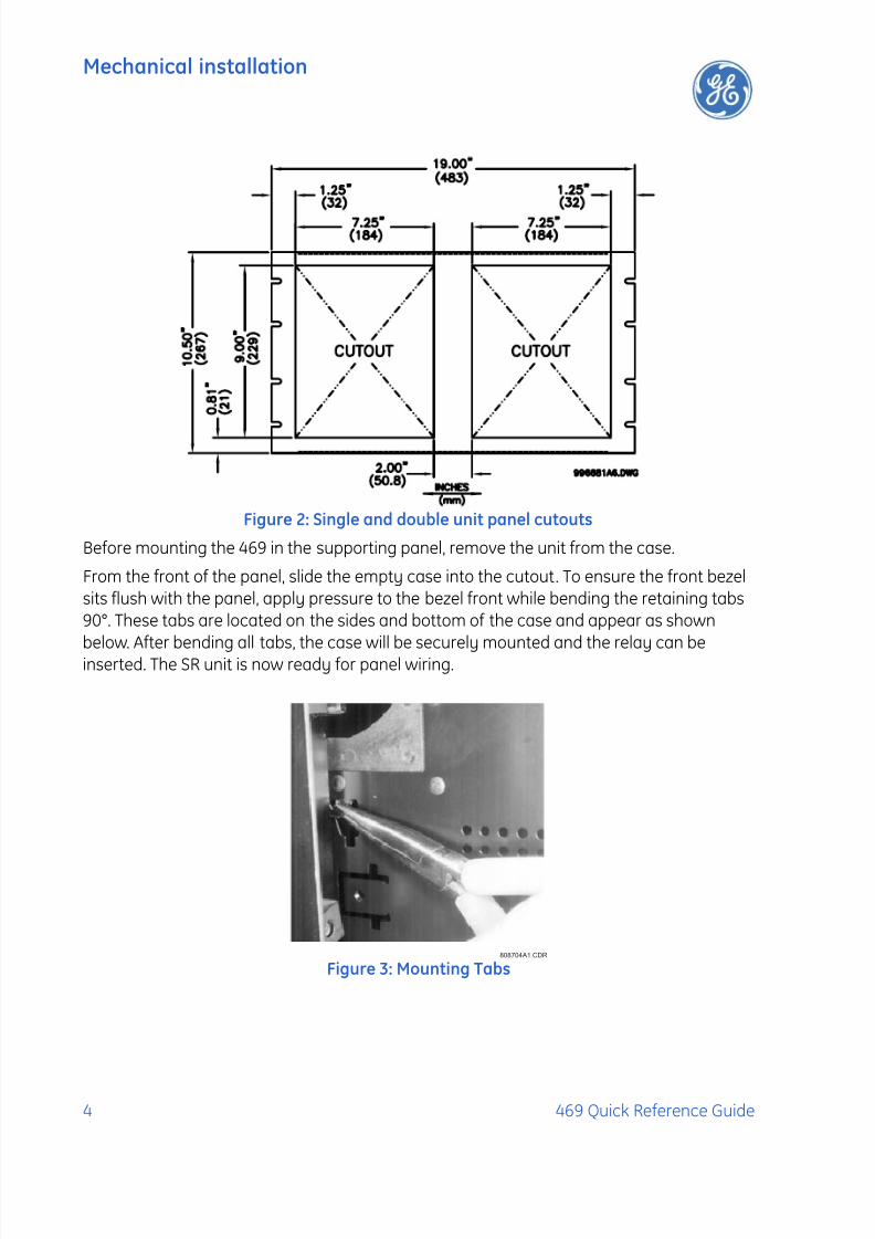
Figure 2: Single and double unit panel cutouts
Before mounting the 469 in the supporting panel, remove the unit from the case.
From the front of the panel, slide the empty case into the cutout. To ensure the front bezelsits flush with the panel, apply pressure to the bezel front while bending the retaining tabs90°. These tabs are located on the sides and bottom of the case and appear as shown
below. After bending all tabs, the case will be securely mounted and the relay can beinserted. The SR unit is now ready for panel wiring.
Figure 3: Mounting Tabs808704A1.CDR

7/27/2019 GEK-106493C
http://slidepdf.com/reader/full/gek-106493c 9/66
Mechanical installation
469 Quick Reference Guide 5
Unit withdrawal
Turn off control power before drawing out or reinserting the relay to prevent
maloperation!
If an attempt is made to install a relay into a non-matching case, the case's
configuration pin will prevent full insertion. Applying a strong force in this
instance will result in damage to the relay and case.
To remove the unit from the case:
1. Open the door by pulling from the top or bottom of its right side. It will rotate to the leftabout its hinges.
2. Press upward on the locking latch, which is located below the handle, and hold in its
raised position. The tip of a small screwdriver may prove helpful in this operation.
Figure 4: Press latch up and pull handle
3. With the latch raised, pull the center of the handle outward. Once disengaged, continuerotating the handle up to the stop position.
Figure 5: Rotating handle to stop position
CAUTION
CAUTION

7/27/2019 GEK-106493C
http://slidepdf.com/reader/full/gek-106493c 10/66
Mechanical installation
6 469 Quick Reference Guide
4. When the stop position is reached, the locking mechanism will release. The relay willnow slide out of the case when pulled from its handle. To free the relay, it maysometimes be necessary to adjust the handle position slightly.
Unit insertion
To insert the unit into the case:
1. Ensure that the model number on the left side of the relay matches the requirements ofthe installation.
2. Raise the locking handle to the highest position.
3. Hold the unit immediately in front of the case and align the rolling guide pins (near thehinges of the relay's handle) with the case's guide slots.
4. Slide the unit into the case until the guide pins on the unit have engaged the guide slots
on either side of the case.5. Once fully inserted, grasp the handle from its center and rotate it down from the raised
position towards the bottom of the relay.
6. Once the unit is fully inserted the latch will be heard to click, locking the handle in thefinal position. The unit is mechanically held in the case by the handle rolling pins, whichcannot be fully lowered to the locked position until the electrical connections arecompletely mated.
No special ventilation requirements need to be observed during the
installation of the unit. The unit does not require cleaning.
Figure 6: Sliding the unit into the case
NOTE

7/27/2019 GEK-106493C
http://slidepdf.com/reader/full/gek-106493c 11/66
Electrical installation
469 Quick Reference Guide 7
ELECTRICAL INSTALLATION
Figure 7: Typical wiring diagram
7/27/2019 GEK-106493C
http://slidepdf.com/reader/full/gek-106493c 12/66
Electrical installation
8 469 Quick Reference Guide
Get familiarized with the Installation Section of this manual. Make sure that the relay isproperly connected, paying special attention to the following:
Ratings and polarities:
• Control voltage matches the ratings and polarities of the relay power supply. Controlpower supplied to the relay must match the installed power supply range. All groundsmust be connected for normal operation regardless of control power supply type. Thelabel found on the left side of the relay specifies its order code or model number. Theinstalled power supply's operating range will be one of the following.
LO: 20 to 60 V DC or 20 to 48 V ACHI: 88 to 300 V DC or 70 to 265 V AC
• The relay ground connections should be connected directly to the ground bus, using theshortest practical path. A tinned copper, braided, shielding and bonding cable should be
used. As a minimum, 96 strands of number 34 AWG should be used. Belden catalognumber 8660 is suitable.
• Current transformer input ratings and polarities match the secondary ratings of thecorresponding CT. For the correct operation of many relay features, the instrumenttransformer polarities shown Figure 7 on page 7 must be followed.
IMPORTANT: The phase and ground current inputs will correctly measure to 20 timesthe current input's nominal rating.
• The phase sequence is user programmable to be either ABC or ACB rotation.
• Voltage transformer input ratings match the secondary ratings of the VT. The 469 relays
have four channels for AC voltage inputs, each with an isolating transformer. The nominalsecondary voltage must be in the 50 to 240 V range. The three phase inputs aredesignated as the ‘bus voltage’. The Bus VT connections most commonly used, delta (oropen delta), is shown in Figure 7 on page 7. Be aware that these voltage channels areinternally connected as wye. This is why the jumper between the phase B terminal andthe Vcom terminal must be installed with a delta connection.
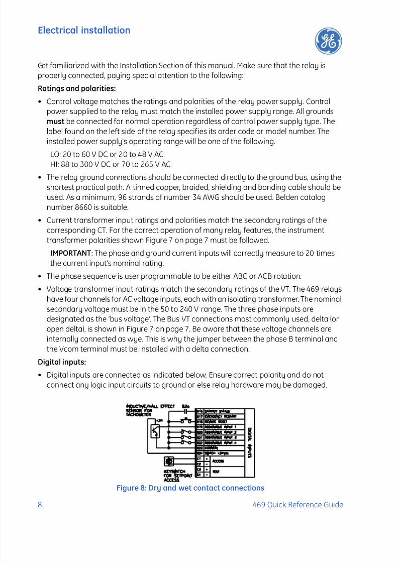
Digital inputs:
• Digital inputs are connected as indicated below. Ensure correct polarity and do notconnect any logic input circuits to ground or else relay hardware may be damaged.
Figure 8: Dry and wet contact connections
7/27/2019 GEK-106493C
http://slidepdf.com/reader/full/gek-106493c 13/66
Accessing setpoints via the front panel
469 Quick Reference Guide 9
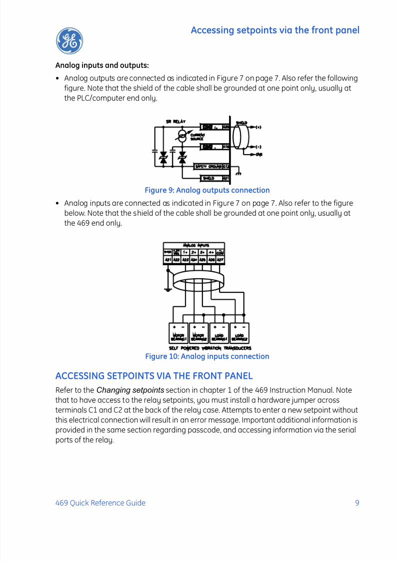
Analog inputs and outputs:
• Analog outputs are connected as indicated in Figure 7 on page 7. Also refer the followingfigure. Note that the shield of the cable shall be grounded at one point only, usually at
the PLC/computer end only.
Figure 9: Analog outputs connection
• Analog inputs are connected as indicated in Figure 7 on page 7. Also refer to the figurebelow. Note that the shield of the cable shall be grounded at one point only, usually atthe 469 end only.
Figure 10: Analog inputs connection
ACCESSING SETPOINTS VIA THE FRONT PANEL
Refer to the Changing setpoints section in chapter 1 of the 469 Instruction Manual. Notethat to have access to the relay setpoints, you must install a hardware jumper acrossterminals C1 and C2 at the back of the relay case. Attempts to enter a new setpoint withoutthis electrical connection will result in an error message. Important additional information isprovided in the same section regarding passcode, and accessing information via the serialports of the relay.

7/27/2019 GEK-106493C
http://slidepdf.com/reader/full/gek-106493c 14/66
Typical application setup
10 469 Quick Reference Guide
TYPICAL APPLICATION SETUP
The relay leaves the factory with setpoints programmed to default values, and it is thesevalues that are shown in all the setpoint message illustrations. Many of these factory
default values can be left unchanged.
At a minimum, the S2 SYSTEM SETUP setpoints must be entered for the system to functioncorrectly. To safeguard against the installation of a relay whose setpoints have not beenentered, the “Warning, 469 Not Programmed” self-test warning is displayed. In addition, the5 Block Start relay will be energized, and the “469 In Service” LED will be off. Once the relayprogramming is complete, the relay should be in the Service state.
For a typical example on how to set the 469 for motor protection, refer to the Application
Example on page 42. In addition to providing typical wiring diagrams, the example coversthe procedure to set the following features of the 469:
System setup for phase, neutral and ground CTs:
• CT primary ratings
• CT secondary ratings
• CT turn ratio
System setup for VTs:
• VT primary ratings
• VT secondary ratings
• VT turn ratio
Setpoints can be accessed with the EnerVista 469 setup software. To access the setpointslisted above, select the Setpoints > System Setup > Current Sensing, Setpoints > System
Setup > Voltage Sensing, and Setpoints > System Setup > Power System menu items.

7/27/2019 GEK-106493C
http://slidepdf.com/reader/full/gek-106493c 15/66
Typical application setup
469 Quick Reference Guide 11
Digital input setpoints:
• Digital input identification
• Digital input asserted logic
• Digital input functionality
To set Digital Inputs by means of the EnerVista 469 setup software, select the Setpoints >
Digital Inputs menu item. The setpoints can be found as sub-pages of the following tree:
Protection setpoints:
Refer to the Application Example on page 42 for details on how to set the 469 MotorManagement Relay for a typical motor.

7/27/2019 GEK-106493C
http://slidepdf.com/reader/full/gek-106493c 16/66
Communicating with the relay via the front panel RS232 port
12 469 Quick Reference Guide
The EnerVista 469 setup software can be used to set the current related protectionelements through the Setpoints > Protection > Current Elements menu item. The setpointswill appear as tabs in the corresponding window:
A similar process can be followed to enable other protection and control feature. For acomplete setpoints list, and for additional information refer to chapter 5 of the 469Instruction Manual.
COMMUNICATING WITH THE RELAY VIA THE FRONT PANEL RS232 PORTTo speed up the process of changing or loading relay setpoints, the use of a computer isstrongly recommended. Refer to the 469 Instruction Manual for additional information onthe serial communication cable to be used to communicate with the relay via the frontport.

7/27/2019 GEK-106493C
http://slidepdf.com/reader/full/gek-106493c 17/66
Connecting EnerVista 469 Setup software with the 469
469 Quick Reference Guide 13
Figure 11: RS232 Connection
CONNECTING ENERVISTA 469 SETUP SOFTWARE WITH THE 469This section is intended as a quick start guide to using the EnerVista 469 Setup software.
Configuring an RS232 connection
Before starting, verify that the serial cable is properly connected to either the RS232 port onthe front panel of the device (for RS232 communications) or to the RS485 terminals on theback of the device (for RS485 communications).
This example demonstrates an RS232 connection. For RS485 communications, the GEMultilin F485 converter will be required. Refer to the F485 manual for additional details. To
configure the relay for Ethernet communications, refer to Configuring Ethernetcommunications on page 16.
1. Install and start the latest version of the EnerVista 469 Setup software (available fromthe EnerVista CD or online from http://www.GEmultilin.com)
2. Click on the Device Setup button to open the Device Setup window and click the Add
Site button to define a new site.
3. Enter the desired site name in the Site Name field. If desired, a short site description canalso be entered along with the display order of devices defined for the site. In this

7/27/2019 GEK-106493C
http://slidepdf.com/reader/full/gek-106493c 18/66
Connecting EnerVista 469 Setup software with the 469
14 469 Quick Reference Guide
example, we will use “Pump Station 1” as the site name. Click the OK button whencomplete.
4. The new site will appear in the upper-left list in the EnerVista 469 Setup window.
5. Click the Add Device button to define the new device.
6. Enter the desired name in the Device Name field and a description (optional) of the site.
7. Select “Serial” from the Interface drop-down list. This will display a number of interfaceparameters that must be entered for proper RS232 functionality.
8. Enter the relay slave address and COM port values (from the S1 469 SETUP SERIAL
PORTS menu) in the Slave Address and COM Port f ields.
9. Enter the physical communications parameters (baud rate and parity) in theirrespective fields. Note that when communicating to the 469 from the front port, thedefault communications settings are: baud rate = 9600, slave address = 1, parity =none, bits = 8, and stop bits = 1. These values cannot be changed.
10. Click the Read Order Code button to connect to the 469 device and upload the ordercode. If a communications error occurs, ensure that the 469 serial communicationsvalues entered in the previous step correspond to the relay setting values.
11. Click OK when the relay order code has been received. The new device will be added tothe Site List window (or Online window) located in the top left corner of the mainEnerVista 469 Setup window.
The 469 Site Device has now been configured for serial communications. Proceed toConnecting to the relay on page 17 to begin communications.
7/27/2019 GEK-106493C
http://slidepdf.com/reader/full/gek-106493c 19/66
Connecting EnerVista 469 Setup software with the 469
469 Quick Reference Guide 15
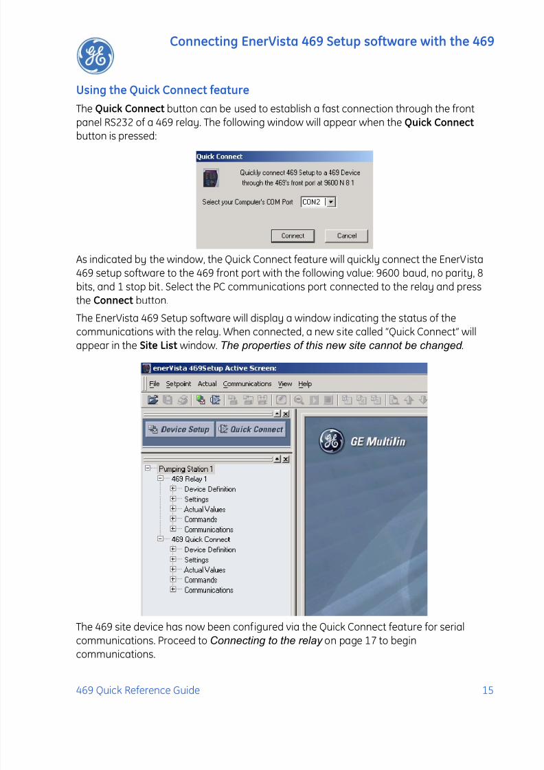
Using the Quick Connect feature
The Quick Connect button can be used to establish a fast connection through the frontpanel RS232 of a 469 relay. The following window will appear when the Quick Connect
button is pressed:
As indicated by the window, the Quick Connect feature will quickly connect the EnerVista
469 setup software to the 469 front port with the following value: 9600 baud, no parity, 8bits, and 1 stop bit. Select the PC communications port connected to the relay and pressthe Connect button.
The EnerVista 469 Setup software will display a window indicating the status of thecommunications with the relay. When connected, a new site called “Quick Connect” willappear in the Site List window. The properties of this new site cannot be changed .
The 469 site device has now been configured via the Quick Connect feature for serialcommunications. Proceed to Connecting to the relay on page 17 to begincommunications.

7/27/2019 GEK-106493C
http://slidepdf.com/reader/full/gek-106493c 20/66
Connecting EnerVista 469 Setup software with the 469
16 469 Quick Reference Guide
Configuring Ethernet communications
Before starting, verify that the Ethernet cable is properly connected to the RJ-45 Ethernetport.
1. Install and start the latest version of the EnerVista 469 Setup software (available fromthe GE enerVista CD). See the previous section for the installation procedure.
2. Click on the Device Setup button to open the Device Setup window and click the Add
Site button to define a new site.
3. Enter the desired site name in the Site Name field. If desired, a short description of sitecan also be entered along with the display order of devices defined for the site. In thisexample, we will use “Pumping Station 2” as the site name. Click the OK button whencomplete.
4. The new site will appear in the upper-left list.
5. Click the Add Device button to define the new device.
6. Enter the desired name in the Device Name field and a description (optional).
7. Select “Ethernet” from the Interface drop-down list. This will display a number ofinterface parameters that must be entered for proper Ethernet functionality.

7/27/2019 GEK-106493C
http://slidepdf.com/reader/full/gek-106493c 21/66
Connecting EnerVista 469 Setup software with the 469
469 Quick Reference Guide 17
• Enter the IP address assigned to the relay.
• Enter the slave address and Modbus port values (from the S1 469 SETUP SERIAL
PORTS menu) in the Slave Address and Modbus Port fields.
8. Click the Read Order Code button to connect to the 469 device and upload the ordercode. If an communications error occurs, ensure that the 469 Ethernet communicationsvalues entered in the previous step correspond to the relay setting values.
9. Click OK when the relay order code has been received. The new device will be added tothe Site List window (or Online window) located in the top left corner of the mainEnerVista 469 Setup window.
The 469 Site Device has now been configured for Ethernet communications. Proceed to thefollowing section to begin communications.
Connecting to the relayNow that the communications parameters have been properly configured, the user caneasily connect to the relay.
1. Expand the site list by double clicking on the site name or clicking on the «+» box to listthe available devices for the given site (for example, in the “Pumping Station 1” siteshown below).
2. Desired device trees can be expanded by clicking the «+» box. The following list ofheaders is shown for each device:
• Device Definitions
• Settings
• Actual Values
• Commands
• Communications
3. Expand the Settings > Relay Setup list item and double click on front panel to open thefront panel settings window as shown below:

7/27/2019 GEK-106493C
http://slidepdf.com/reader/full/gek-106493c 22/66
Connecting EnerVista 469 Setup software with the 469
18 469 Quick Reference Guide
Figure 12: Main window after connection
4. The front panel settings window will open with a corresponding status indicator on thelower left of the EnerVista 469 Setup window.
5. If the status indicator is red, verify that the serial cable is properly connected to therelay, and that the relay has been properly configured for communications (stepsdescribed earlier).
The front panel setpoints can now be edited, printed, or changed according to userspecifications. Other setpoint and commands windows can be displayed and edited in asimilar manner. Actual values windows are also available for display. These windows can belocked, arranged, and resized at will.
Refer to the EnerVista 469 Setup help file for additional information about the
using the software.
-Expand the Site List by doubleclicking or by selecting the [+] box
Communications Status Indicator Green = OK, Red = No Comms
NOTE
7/27/2019 GEK-106493C
http://slidepdf.com/reader/full/gek-106493c 23/66
Working with setpoints
469 Quick Reference Guide 19
WORKING WITH SETPOINTS
Engaging a device
The EnerVista 469 Setup software may be used in on-line mode (relay connected) todirectly communicate with a 469 relay. Communicating relays are organized and groupedby communication interfaces and into sites. Sites may contain any number of relays
selected from the SR or UR product series.
Entering setpoints
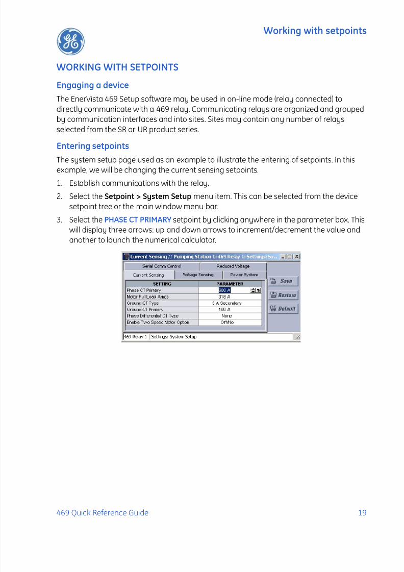
The system setup page used as an example to illustrate the entering of setpoints. In thisexample, we will be changing the current sensing setpoints.
1. Establish communications with the relay.
2. Select the Setpoint > System Setup menu item. This can be selected from the devicesetpoint tree or the main window menu bar.
3. Select the PHASE CT PRIMARY setpoint by clicking anywhere in the parameter box. Thiswill display three arrows: up and down arrows to increment/decrement the value andanother to launch the numerical calculator.

7/27/2019 GEK-106493C
http://slidepdf.com/reader/full/gek-106493c 24/66
Working with setpoints
20 469 Quick Reference Guide
4. Clicking the arrow at the end of the box displays a numerical keypad interface thatallows the user to enter a value within the setpoint range displayed near the top of thekeypad:
5. Click Accept to exit from the keypad and keep the new value. Click on Cancel to exitform the keypad and retain the old value.
6. For setpoints requiring non-numerical pre-set values (e.g. VT CONNECTION TYPE above,in the Voltage Sensing Tab), clicking anywhere within the setpoint value box displays adrop down selection menu arrow. Click on the arrow to select the desired setpoint.
7. For setpoints requiring an alphanumeric text string (e.g. message scratchpadmessages), the value may be entered directly within the setpoint value box.
8. Click on Save in the system setup dialog box to save the values into the 469. Click Yes toaccept any changes. Click No, and then Restore, to retain previous values.

7/27/2019 GEK-106493C
http://slidepdf.com/reader/full/gek-106493c 25/66
Working with setpoint files
469 Quick Reference Guide 21
WORKING WITH SETPOINT FILES
File support
Opening any EnerVista 469 Setup file will automatically launch the application or providefocus to the already opened application. If the file was a setpoints file (that is, it has a '469'extension), which had been removed from the settings list tree menu, it will be added back
to the settings list tree menu.
New files will automatically added to the tree, which is sorted alphabetically with respect tosettings file names.
Setpoints files overview
The EnerVista 469 Setup software interface supports three ways of handling changes torelay Setpoints:
• In off-line mode (relay disconnected) to create or edit relay setpoints files for laterdownload to communicating relays.
• Directly modifying while connected to a communicating relay then saving the setpointswhen complete.
• Creating/editing setpoints files while connected to a communicating relay, then savingthe setpoints when complete.
Setpoints files are organized on the basis of file names assigned by the user. A setpoints filecontains data pertaining to the following types of relay setpoints:
• Device definition• Product setup
• System setup
• Digital inputs
• Output relays
• Protection elements
• Monitoring functions
• Analog inputs and outputs
• Relay testing
• Settings for two speed motors
• User memory map setting tool
Factory default values are supplied and can be restored after any changes.
The EnerVista 469 Setup software displays relay setpoints with the same hierarchy as thefront relay panel display. For specific details on setpoints, refer to chapter 5 of the 469Instruction Manual.

7/27/2019 GEK-106493C
http://slidepdf.com/reader/full/gek-106493c 26/66
Working with setpoint files
22 469 Quick Reference Guide
Downloading and saving setpoints files
Setpoints must be saved to a file on the local PC before performing any firmware upgrades.Saving setpoints is also highly recommended before making any setpoint changes or
creating new setpoint files.
Within the EnerVista 469 Setup window, setpoint files are accessed in the settings Listcontrol bar window or the f ile window. Use the following procedure to download and savesetpoint files to a local PC.
1. Ensure that the site and corresponding device(s) have been properly defined andconfigured as shown in Connecting to the relay on page 17.
2. Select the desired device from the site list.
3. Select the File > Read Settings from Device menu item to obtain settings informationfrom the device.
4. After a few seconds of data retrieval, the EnerVista 469 Setup software will display thefollowing window, requesting the name and destination path of the setpoint file. Thecorresponding file extension will be automatically assigned. Press Save to complete the
process. A new entry will be added to the tree indicating the path and file name.
Adding setpoints files to the environment
The EnerVista 469 Setup software provides the capability to review and manage a largegroup of setpoint files. Use the following procedure to add a new or existing file to the list.
1. In file pane, right click on Files, and select the Add Existing Setting File item as shown:
2. The Open dialog box will appear, prompting the user to select a previously savedsetpoint file. As for any other MS Windows® application, browse for the file to be added,and then click Open. The new file and complete path will be added to the file list.

7/27/2019 GEK-106493C
http://slidepdf.com/reader/full/gek-106493c 27/66
Working with setpoint files
469 Quick Reference Guide 23
Creating a new setpoint file
The EnerVista 469 Setup software allows the user to create new setpoint files independentof a connected device. These can be uploaded to a relay at a later date. The following
procedure illustrates how to create new setpoint files.
1. In the File pane, right click on ‘File’ and select the New Settings File item. The EnerVista469 Setup software displays the following box will appear, allowing for theconfiguration of the setpoint file for the correct firmware version. It is important todefine the correct firmware version to ensure that setpoints not available in a particularversion are not downloaded into the relay.
2. Select the Firmware Version for the new setpoint file.
3. For future reference, enter some useful information in the Description box to facilitatethe identification of the device and the purpose of the f ile.
4. To select a file name and path for the new file, click the button beside the Enter FileName box.
5. Select the file name and path to store the file, or select any displayed file name toupdate an existing file. All 469 setpoint files should have the extension ‘469’ (forexample, ‘motor1.469’).
6. Click Save and OK to complete the process. Once this step is completed, the new f ile,with a complete path, will be added to the EnerVista 469 Setup software environment.
Upgrading setpoint files to a new revision
It is often necessary to upgrade the revision code for a previously saved setpoint file afterthe 469 f irmware has been upgraded (for example, this is required for f irmware upgrades).This is illustrated in the following procedure.
1. Establish communications with the 469 relay.

7/27/2019 GEK-106493C
http://slidepdf.com/reader/full/gek-106493c 28/66
Working with setpoint files
24 469 Quick Reference Guide
2. Select the Actual > Product Information menu item and record the Software Revisionidentifier of the relay firmware as shown below.
3. Load the setpoint file to be upgraded into the EnerVista 469 Setup environment asdescribed in Adding setpoints files to the environment on page 22.
4. In the File pane, select the saved setpoint file.
5. From the main window menu bar, select the File > Properties menu item and note theversion code of the setpoint file. If this version (e.g. 4.0X shown below) is different than
the Software Revision code noted in step 2, select a New File Version that matches theSoftware Revision code from the pull-down menu.
6. For example, if the software revision is 2.80 and the current setpoint file revision is 4.00,change the setpoint file revision to “4.0X”, as shown below.
7. When complete, click Convert to convert the setpoint file to the desired revision. Adialog box will request confirmation. See Loading setpoints from a file on page 26 forinstructions on loading this setpoint file into the 469.
Select the desired setpoint versionfrom this menu. The 4.0x indicatesversions 4.00, 4.01, 4.02, etc.
Enter any special commentsabout the setpoint file here.
7/27/2019 GEK-106493C
http://slidepdf.com/reader/full/gek-106493c 29/66
Working with setpoint files
469 Quick Reference Guide 25
Printing setpoints and actual values
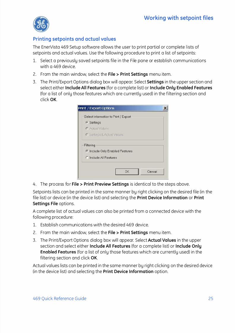
The EnerVista 469 Setup software allows the user to print partial or complete l ists ofsetpoints and actual values. Use the following procedure to print a list of setpoints:
1. Select a previously saved setpoints file in the File pane or establish communicationswith a 469 device.
2. From the main window, select the File > Print Settings menu item.
3. The Print/Export Options dialog box will appear. Select Settings in the upper section andselect either Include All Features (for a complete list) or Include Only Enabled Features (for a list of only those features which are currently used) in the filtering section andclick OK.
4. The process for File > Print Preview Settings is identical to the steps above.
Setpoints lists can be printed in the same manner by right clicking on the desired file (in thefile list) or device (in the device list) and selecting the Print Device Information or Print
Settings File options.
A complete list of actual values can also be printed from a connected device with thefollowing procedure:
1. Establish communications with the desired 469 device.
2. From the main window, select the File > Print Settings menu item.3. The Print/Export Options dialog box will appear. Select Actual Values in the upper
section and select either Include All Features (for a complete list) or Include Only
Enabled Features (for a list of only those features which are currently used) in thefiltering section and click OK.
Actual values lists can be printed in the same manner by right clicking on the desired device(in the device list) and selecting the Print Device Information option.

7/27/2019 GEK-106493C
http://slidepdf.com/reader/full/gek-106493c 30/66
Working with setpoint files
26 469 Quick Reference Guide
Loading setpoints from a file
An error message will occur when attempting to download a setpoint file with arevision number that does not match the relay firmware. If the firmware has been
upgraded since saving the setpoint file, see Upgrading setpoint files to a newrevision on page 23 for instructions on changing the revision of a setpoint file.
The following procedure illustrates how to load setpoints from a file. Before loading asetpoints file, it must f irst be added to the EnerVista 469 Setup environment as described in Adding setpoints files to the environment on page 22.
1. Select the previously saved setpoints file from the File pane of the EnerVista 469 Setupsoftware main window.
2. Select the File > Properties menu item and verify that the corresponding file is fullycompatible with the hardware and firmware version of the target relay. If the versions
are not identical, see Upgrading setpoint files to a new revision on page 23 for detailson changing the setpoints file version.
3. Right-click on the selected file and select the Write Settings to Device item.
4. The EnerVista 469 Setup software will generate the following warning message, toremind the user to remove the relay from service, before attempting to load setpointsinto an in-service relay.:
5. Select the target relay from the list of devices shown and click Send. If there is anincompatibility, an error of the following type will occur.
6. If there are no incompatibilities between the target device and the setpoints file, thedata will be transferred to the relay. An indication of the percentage completed will be
shown in the bottom of the main menu.
WARNING
7/27/2019 GEK-106493C
http://slidepdf.com/reader/full/gek-106493c 31/66
Upgrading relay firmware
469 Quick Reference Guide 27
UPGRADING RELAY FIRMWARE
Description
To upgrade the 469 firmware, follow the procedures listed in this section. Upon successfulcompletion of this procedure, the 469 will have new f irmware installed with the originalsetpoints.
Firmware files are available from the GE Multilin website at http://www.GEmultilin.com.
Saving setpoints to a file
Before upgrading firmware, it is very important to save the current 469 settings to a f ile onyour PC. After the f irmware has been upgraded, it will be necessary to load this f ile backinto the 469.
Refer to Downloading and saving setpoints files on page 22 for details on saving relaysetpoints to a file.
Loading new firmware
Loading new firmware into the 469 flash memory is accomplished as follows:
1. Connect the relay to the local PC and save the setpoints to a file as shown inDownloading and saving setpoints files on page 22.
2. Select the Communications > Update Firmware menu item.
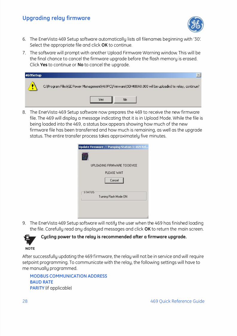
3. The following warning message will appear. Select Yes to proceed or No the cancel the
process. Do not proceed unless you have saved the current setpoints.
4. An additional message will be displayed to ensure the PC is connected to the relay frontport , as the 469 cannot be upgraded via the rear RS485 ports.
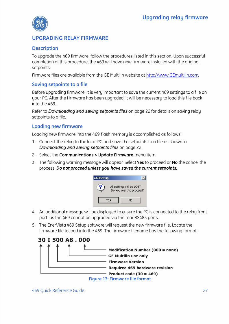
5. The EnerVista 469 Setup software will request the new firmware file. Locate thefirmware file to load into the 469. The firmware filename has the following format:
Figure 13: Firmware file format
30 I 500 A8 . 000
Modification Number (000 = none)
GE Multilin use only
Firmware Version
Required 469 hardware revision
Product code (30 = 469)
7/27/2019 GEK-106493C
http://slidepdf.com/reader/full/gek-106493c 32/66
Upgrading relay firmware
28 469 Quick Reference Guide
6. The EnerVista 469 Setup software automatically lists all filenames beginning with ‘30’.Select the appropriate file and click OK to continue.
7. The software will prompt with another Upload Firmware Warning window. This will be
the final chance to cancel the firmware upgrade before the flash memory is erased.Click Yes to continue or No to cancel the upgrade.
8. The EnerVista 469 Setup software now prepares the 469 to receive the new firmware
file. The 469 will display a message indicating that it is in Upload Mode. While the file isbeing loaded into the 469, a status box appears showing how much of the newfirmware file has been transferred and how much is remaining, as well as the upgradestatus. The entire transfer process takes approximately five minutes.
9. The EnerVista 469 Setup software will notify the user when the 469 has finished loadingthe file. Carefully read any displayed messages and click OK to return the main screen.
Cycling power to the relay is recommended after a firmware upgrade.
After successfully updating the 469 f irmware, the relay will not be in service and will requiresetpoint programming. To communicate with the relay, the following settings will have tome manually programmed.
MODBUS COMMUNICATION ADDRESS
BAUD RATE
PARITY (if applicable)
NOTE

7/27/2019 GEK-106493C
http://slidepdf.com/reader/full/gek-106493c 33/66
Advanced EnerVista 469 Setup features
469 Quick Reference Guide 29
When communications is established, the saved setpoints must be reloaded back into therelay. See Loading setpoints from a file on page 26 for details.
Modbus addresses assigned to f irmware modules, features, settings, and corresponding
data items (i.e. default values, min/max values, data type, and item size) may changeslightly from version to version of firmware.
The addresses are rearranged when new features are added or existing features areenhanced or modified. The EEPROM DATA ERROR message displayed after upgrading/downgrading the firmware is a resettable, self-test message intended to inform users thatthe Modbus addresses have changed with the upgraded firmware. This message does notsignal any problems when appearing after f irmware upgrades.
ADVANCED ENERVISTA 469 SETUP FEATURES
Triggered events
While the interface is in either on-line or off-line mode, data generated by triggeredspecified parameters can be viewed and analyzed via one of the following:
• Event Recorder: The event recorder captures contextual data associated with the last256 events, listed in chronological order from most recent to the oldest.
• Oscillography: The oscillography waveform traces provide a visual display of powersystem data captured during specific triggered events.
Waveform capture (trace memory)
The EnerVista 469 Setup software can be used to capture waveforms (or view tracememory) from the 469 relay at the instance of a trip. A maximum of 128 cycles can becaptured and the trigger point can be adjusted to anywhere within the set cycles. Amaximum of 16 traces can be buffered (stored) with the buffer/cycle trade-off.
The following waveforms can be captured:
• Phase A, B, and C currents (Ia, Ib, and Ic)
• Differential A, B, and C currents (Idiffa, Idiffb, and Idiffc)
• Ground currents (Ig)
• Phase A-N, B-N, and C-N voltages (V an, V bn, and V cn) for wye connections• Phase A-B and B-C (V ab and V bc) for open-delta connections
7/27/2019 GEK-106493C
http://slidepdf.com/reader/full/gek-106493c 34/66
Advanced EnerVista 469 Setup features
30 469 Quick Reference Guide
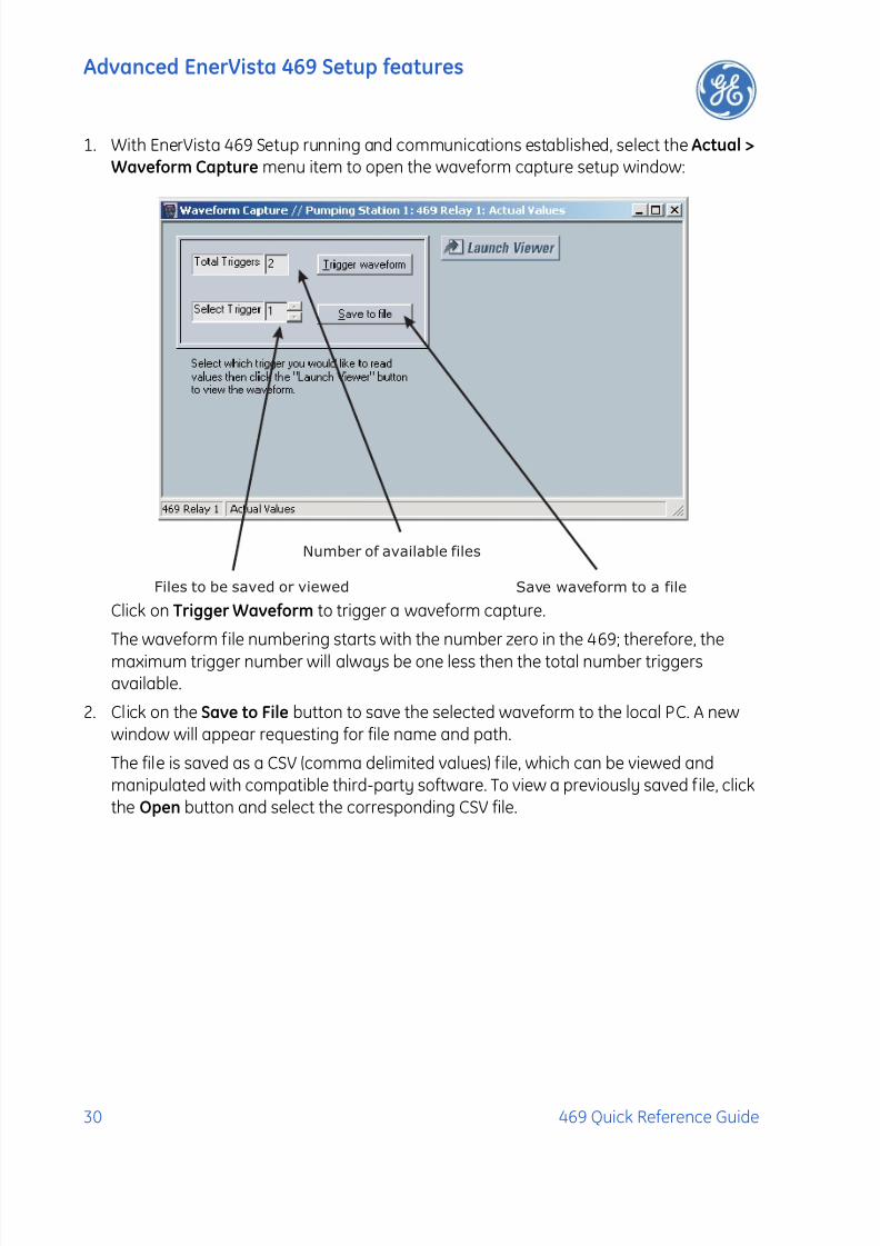
1. With EnerVista 469 Setup running and communications established, select the Actual >
Waveform Capture menu item to open the waveform capture setup window:
Click on Trigger Waveform to trigger a waveform capture.
The waveform file numbering starts with the number zero in the 469; therefore, the
maximum trigger number will always be one less then the total number triggersavailable.
2. Click on the Save to File button to save the selected waveform to the local PC. A newwindow will appear requesting for file name and path.
The file is saved as a CSV (comma delimited values) f ile, which can be viewed andmanipulated with compatible third-party software. To view a previously saved file, clickthe Open button and select the corresponding CSV file.
Number of available files
Files to be saved or viewed Save waveform to a file
7/27/2019 GEK-106493C
http://slidepdf.com/reader/full/gek-106493c 35/66
Advanced EnerVista 469 Setup features
469 Quick Reference Guide 31
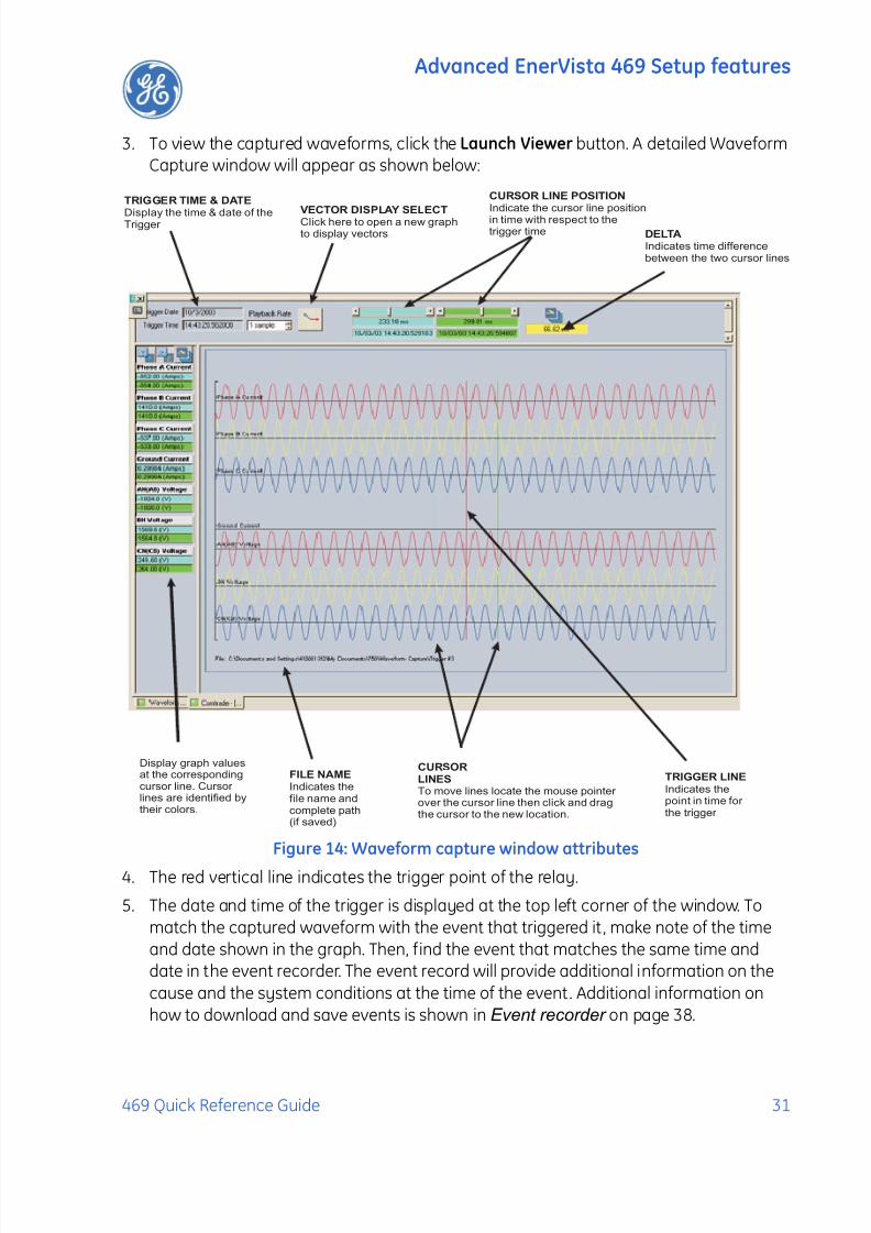
3. To view the captured waveforms, click the Launch Viewer button. A detailed WaveformCapture window will appear as shown below:
Figure 14: Waveform capture window attributes
4. The red vertical line indicates the trigger point of the relay.
5. The date and time of the trigger is displayed at the top left corner of the window. Tomatch the captured waveform with the event that triggered it , make note of the timeand date shown in the graph. Then, find the event that matches the same time anddate in the event recorder. The event record will provide additional information on the
cause and the system conditions at the time of the event. Additional information onhow to download and save events is shown in Event recorder on page 38.
Display graph valuesat the correspondingcursor line. Cursor lines are identified bytheir colors.
CURSOR
LINES
To move lines locate the mouse pointer over the cursor line then click and dragthe cursor to the new location.
DELTA
Indicates time differencebetween the two cursor lines
TRIGGER LINE
Indicates thepoint in time for the trigger
FILE NAME
Indicates thefile name andcomplete path(if saved)
TRIGGER TIME & DATE
Display the time & date of theTrigger
VECTOR DISPLAY SELECT
Click here to open a new graphto display vectors
CURSOR LINE POSITION
Indicate the cursor line positionin time with respect to thetrigger time
7/27/2019 GEK-106493C
http://slidepdf.com/reader/full/gek-106493c 36/66
Advanced EnerVista 469 Setup features
32 469 Quick Reference Guide
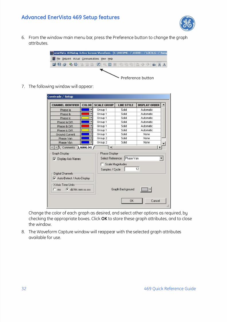
6. From the window main menu bar, press the Preference button to change the graphattributes.
7. The following window will appear:
Change the color of each graph as desired, and select other options as required, bychecking the appropriate boxes. Click OK to store these graph attributes, and to close
the window.8. The Waveform Capture window will reappear with the selected graph attributes
available for use.
Preference button
7/27/2019 GEK-106493C
http://slidepdf.com/reader/full/gek-106493c 37/66
Advanced EnerVista 469 Setup features
469 Quick Reference Guide 33
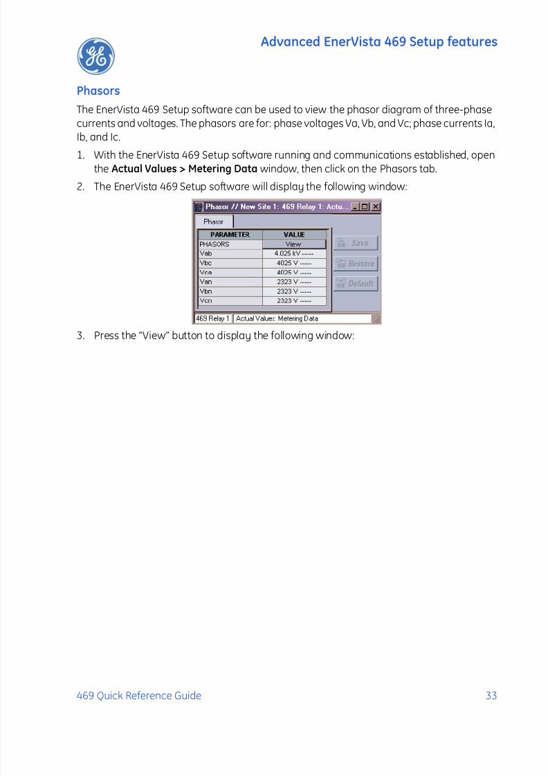
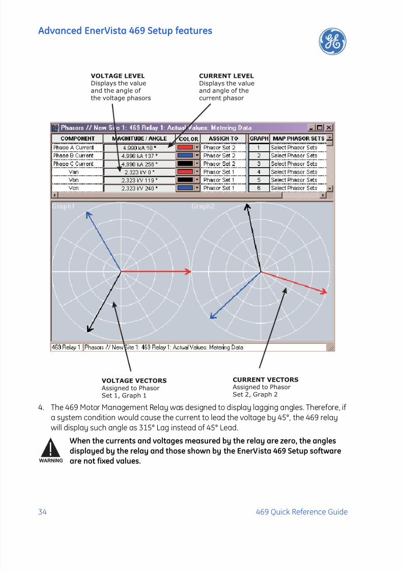
Phasors
The EnerVista 469 Setup software can be used to view the phasor diagram of three-phasecurrents and voltages. The phasors are for: phase voltages Va, Vb, and Vc; phase currents Ia,
Ib, and Ic.
1. With the EnerVista 469 Setup software running and communications established, openthe Actual Values > Metering Data window, then click on the Phasors tab.
2. The EnerVista 469 Setup software will display the following window:
3. Press the “View” button to display the following window:
7/27/2019 GEK-106493C
http://slidepdf.com/reader/full/gek-106493c 38/66
Advanced EnerVista 469 Setup features
34 469 Quick Reference Guide
4. The 469 Motor Management Relay was designed to display lagging angles. Therefore, ifa system condition would cause the current to lead the voltage by 45°, the 469 relaywill display such angle as 315° Lag instead of 45° Lead.
When the currents and voltages measured by the relay are zero, the angles
displayed by the relay and those shown by the EnerVista 469 Setup software
are not fixed values.
VOLTAGE VECTORS
Assigned to PhasorSet 1, Graph 1
CURRENT VECTORS
Assigned to PhasorSet 2, Graph 2
CURRENT LEVEL
Displays the valueand angle of the
current phasor
VOLTAGE LEVEL
Displays the valueand the angle of
the voltage phasors
WARNING

7/27/2019 GEK-106493C
http://slidepdf.com/reader/full/gek-106493c 39/66
Advanced EnerVista 469 Setup features
469 Quick Reference Guide 35
Trending (data logger)
The trending or data logger feature is used to sample and record up to eight actual valuesat an interval defined by the user. Several parameters can be trended and graphed at
sampling periods ranging from 1 second up to 1 hour. The parameters which can betrended by the EnerVista 469 Setup software are:
• Currents/Voltages:
Phase Currents A, B, and C, and Average Phase Current
Motor LoadCurrent UnbalanceGround CurrentDifferential Currents A, B, and CSystem Frequency
Voltages Vab, Vbc, Vca Van, Vbn & Vcn• Power:
Power FactorReal (kW or hp) Reactive (kvar), and Apparent (kVA) PowerPositive WatthoursPositive and Negative VarhoursTorque
• Temperature:
Hottest Stator RTD
Thermal Capacity UsedRTDs 1 through 12
• Demand:
CurrentPeak CurrentReactive PowerPeak Reactive PowerApparent PowerPeak Apparent Power
• Others:
Analog Inputs 1, 2, 3, and 4Tachometer
7/27/2019 GEK-106493C
http://slidepdf.com/reader/full/gek-106493c 40/66
Advanced EnerVista 469 Setup features
36 469 Quick Reference Guide
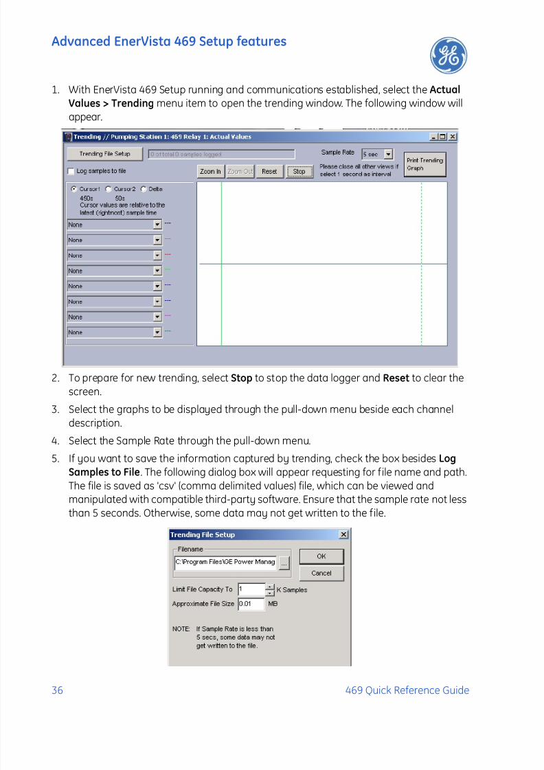
1. With EnerVista 469 Setup running and communications established, select the Actual
Values > Trending menu item to open the trending window. The following window willappear.
2. To prepare for new trending, select Stop to stop the data logger and Reset to clear thescreen.
3. Select the graphs to be displayed through the pull-down menu beside each channeldescription.
4. Select the Sample Rate through the pull-down menu.
5. If you want to save the information captured by trending, check the box besides Log
Samples to File. The following dialog box will appear requesting for file name and path.The file is saved as 'csv' (comma delimited values) file, which can be viewed andmanipulated with compatible third-party software. Ensure that the sample rate not lessthan 5 seconds. Otherwise, some data may not get written to the file.
7/27/2019 GEK-106493C
http://slidepdf.com/reader/full/gek-106493c 41/66
Advanced EnerVista 469 Setup features
469 Quick Reference Guide 37
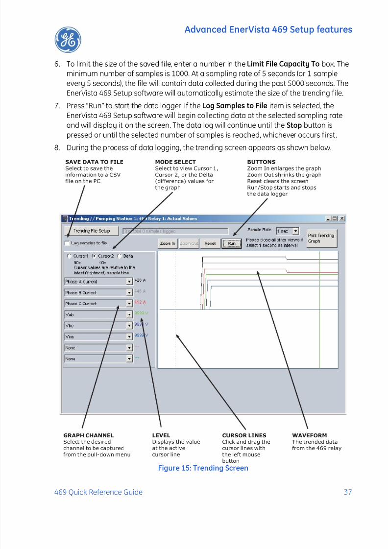
6. To limit the size of the saved file, enter a number in the Limit File Capacity To box. Theminimum number of samples is 1000. At a sampling rate of 5 seconds (or 1 sampleevery 5 seconds), the file will contain data collected during the past 5000 seconds. The
EnerVista 469 Setup software will automatically estimate the size of the trending file.7. Press “Run” to start the data logger. If the Log Samples to File item is selected, the
EnerVista 469 Setup software will begin collecting data at the selected sampling rateand will display it on the screen. The data log will continue until the Stop button ispressed or until the selected number of samples is reached, whichever occurs f irst.
8. During the process of data logging, the trending screen appears as shown below.
Figure 15: Trending Screen
SAVE DATA TO FILE
Select to save the
information to a CSVfile on the PC
MODE SELECT
Select to view Cursor 1,
Cursor 2, or the Delta(difference) values for
the graph
BUTTONS
Zoom In enlarges the graph
Zoom Out shrinks the graphReset clears the screen
Run/Stop starts and stops
the data logger
GRAPH CHANNELSelect the desired
channel to be captured
from the pull-down menu
LEVEL
Displays the valueat the active
cursor line
WAVEFORM
The trended datafrom the 469 relay
CURSOR LINES
Click and drag thecursor lines with
the left mousebutton
7/27/2019 GEK-106493C
http://slidepdf.com/reader/full/gek-106493c 42/66
Advanced EnerVista 469 Setup features
38 469 Quick Reference Guide
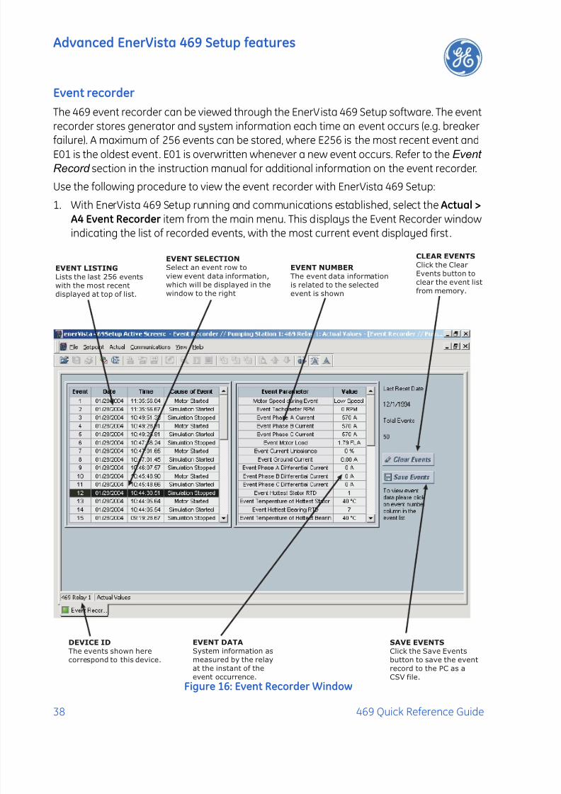
Event recorder
The 469 event recorder can be viewed through the EnerVista 469 Setup software. The eventrecorder stores generator and system information each time an event occurs (e.g. breaker
failure). A maximum of 256 events can be stored, where E256 is the most recent event andE01 is the oldest event. E01 is overwritten whenever a new event occurs. Refer to the Event
Record section in the instruction manual for additional information on the event recorder.
Use the following procedure to view the event recorder with EnerVista 469 Setup:
1. With EnerVista 469 Setup running and communications established, select the Actual >
A4 Event Recorder item from the main menu. This displays the Event Recorder windowindicating the list of recorded events, with the most current event displayed first .
Figure 16: Event Recorder Window
EVENT LISTING
Lists the last 256 eventswith the most recent
displayed at top of list.
EVENT SELECTION
Select an event row to
view event data information,which will be displayed in the
window to the right
CLEAR EVENTS
Click the Clear
Events button to
clear the event list
from memory.
SAVE EVENTS
Click the Save Events
button to save the event
record to the PC as a
CSV file.
EVENT DATA
System information as
measured by the relay
at the instant of the
event occurrence.
DEVICE ID
The events shown here
correspond to this device.
EVENT NUMBER
The event data informationis related to the selected
event is shown
7/27/2019 GEK-106493C
http://slidepdf.com/reader/full/gek-106493c 43/66
Advanced EnerVista 469 Setup features
469 Quick Reference Guide 39
2. To view detailed information for a given event and the system information at themoment of the event occurrence, change the event number on the Select Event box.
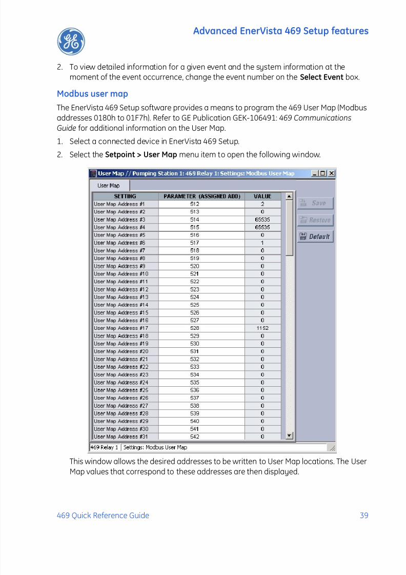
Modbus user map
The EnerVista 469 Setup software provides a means to program the 469 User Map (Modbusaddresses 0180h to 01F7h). Refer to GE Publication GEK-106491: 469 Communications
Guide for additional information on the User Map.
1. Select a connected device in EnerVista 469 Setup.
2. Select the Setpoint > User Map menu item to open the following window.
This window allows the desired addresses to be written to User Map locations. The UserMap values that correspond to these addresses are then displayed.

7/27/2019 GEK-106493C
http://slidepdf.com/reader/full/gek-106493c 44/66
Advanced EnerVista 469 Setup features
40 469 Quick Reference Guide
Viewing actual values
You can view real-time relay data such as input/output status and measured parameters.From the main window menu bar, selecting Actual Values opens a window with tabs, each
tab containing data in accordance to the following list:
1. Motor and System Status:
• Motor status either stopped, starting, or running. It includes values such as motor load,thermal capacity used, motor speed, and instantaneous values of power system
quantities.
• Thee status of digital inputs.
• Last trip information, including values such as cause of last trip, time and date of trip,
motor speed and load at the time of trip, pre-trip temperature measurements, pre-tripanalog inputs values, and pre-trip instantaneous values of power system quantities.
• Active alarms.
• Relay date and time.
• Present blocking conditions.
• General system status indication including the status of output relays, active pickup,alarm and trip conditions.
2. Metering Data:
• Instantaneous current measurements including phase, differential, unbalance,ground, average, motor load, and differential currents.
• RTD Temperatures including hottest stator RTD.
• Instantaneous phase to phase and phase to ground voltages (depending on the VTconnections), average voltage, and system frequency.
• Motor Speed
• Power Quantities including Apparent, Real and Reactive Power.
• Current and power demand including peak values.
• Analog inputs
• Vector information.
3. Motor Learned Data:
• Learned Acceleration Time
• Learned Starting Current
• Learned Starting Capacity
• Last Acceleration Time
• Last Starting Current
• Last Starting Capacity
7/27/2019 GEK-106493C
http://slidepdf.com/reader/full/gek-106493c 45/66
Advanced EnerVista 469 Setup features
469 Quick Reference Guide 41
• Average Motor Load Learned
4. Maintenance data. This is useful statistical information that may be used for preventivemaintenance. It includes:
• Trip counters
• General counter such as Number of Motor Starts, Number of Emergency Restarts,Number of Starter Operations, Digital Counter for other purposes not listed above.
• Timers such as Motor Running Hours, Time Between Starts Timer, and five StartTimers used to calculate the average start time of the motor.
5. RTD Learned Data, which includes the maximum temperature measured by each ofthe 12 RTDs.
6. Event recorder downloading tool.
7. Product information including model number, firmware version, additional productinformation, and calibration dates.
8. Oscillography and data logger downloading tool.
Selecting an actual values window also opens the actual values tree from the
corresponding device in the site list and highlights the current location in the hierarchy.
For complete details on actual values, refer to Chapter 6 of the 469 Instruction Manual.
To view a separate window for each group of actual values, select the desired item from the
tree, and double click with the left mouse button. Each group will be opened on a separatetab. The windows can be re-arranged to maximize data viewing as shown in the following
figure (showing actual current, voltage, and motor status values tiled in the same window):

7/27/2019 GEK-106493C
http://slidepdf.com/reader/full/gek-106493c 46/66
Application Example
42 469 Quick Reference Guide
Figure 17: Actual Values Display
APPLICATION EXAMPLE
Description
The 469 Motor Management Relay contains many features designed to accommodate a
wide range of motor management applications. This chapter is provided to guide you, thefirst time user, through a real-world application.
The following is typical example of how to determine the relay setpoints for a specificmotor that has been applied conservatively. This is only an example and may not addressall issues relating to your specific application. It is recommended that your local protection
engineer determine the setpoints for your motor protective relaying application. Refer tofigures 1 to 3 for schematic diagrams related to this example.
Important points to keep in mind before developing settings for any multifunctionnumerical device like the 469 Motor Management relay:
7/27/2019 GEK-106493C
http://slidepdf.com/reader/full/gek-106493c 47/66
Application Example
469 Quick Reference Guide 43
Gather system data, including, but not l imited to:
• CT primary and secondary ratings for all the CTs that will be used to feed the relay
• Motor nameplate data.
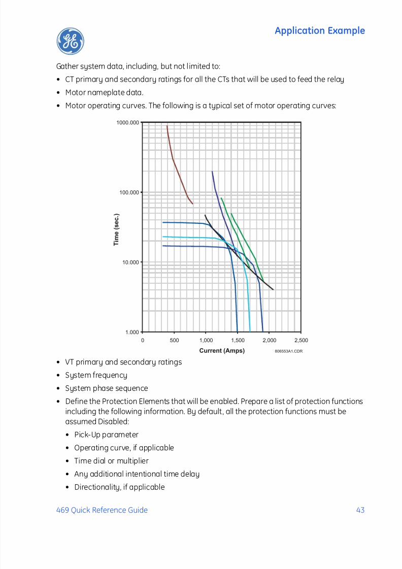
• Motor operating curves. The following is a typical set of motor operating curves:
• VT primary and secondary ratings
• System frequency
• System phase sequence
• Define the Protection Elements that will be enabled. Prepare a list of protection functionsincluding the following information. By default, all the protection functions must beassumed Disabled:
• Pick-Up parameter
• Operating curve, if applicable
• Time dial or multiplier
• Any additional intentional time delay
• Directionality, if applicable
806553A1.CDR
1.000
10.000
100.000
1000.000
0 500 1,000 1,500 2,000 2,500
Current (Amps)
T i m e ( s e c . )
7/27/2019 GEK-106493C
http://slidepdf.com/reader/full/gek-106493c 48/66
Application Example
44 469 Quick Reference Guide
• Define how many output contacts will be energized in response to a given protectionfunction. Note that the 469 relay can be programmed to TRIP or ALARM and, at the sametime, to energize one, a combination, or both auxiliary relays during the process.
• Define if the output relays will be set as failsafe type.• Define if the 469 will be used to start the motor. If that will be the case, gather
information on the conditions that will be used to execute the command.
• Define if the 469 will be involved in the process of starting the motor, particularly forreduced voltage start applications.
• Define if the 469 will be applied a multi speed applications.
• Define if the relay will be used to monitor the status of the starter or breaker. It is stronglyrecommended that the 469 be always programmed to monitor the status of thedisconnecting device, by means of a dry contact connected to one of the digital inputs of
the relay. Use an auxiliary contact from the breaker or starter either a normally opencontact, 52a, which is normally in open position when the disconnecting device is open,or a normally closed contact, 52b, which is in close position when the breaker or starteris open.
• If the relay will be used to respond to digital inputs, prepare a list of them including:
• Logic Input name.
• Condition by which the logic input would be considered asserted.
• Function that the logic input will initiate within the 469.
• If the relay will be used to perform Monitoring functions and act upon certain conditions,gather information such as:
• Minimum and maximum values
• Alarm and trip values
• Time delays
It is important to familiarize yourself with the relay protection and control functions beforesetting up the relay.
To start, simply power on the unit, and follow the instructions in this tutorial. The exampleassumes the following system characteristics. It also assumes that relay setpoints areunaltered from their factory default values.
Refer to the following figures for schematics related to this application example.
7/27/2019 GEK-106493C
http://slidepdf.com/reader/full/gek-106493c 49/66
Application Example
469 Quick Reference Guide 45
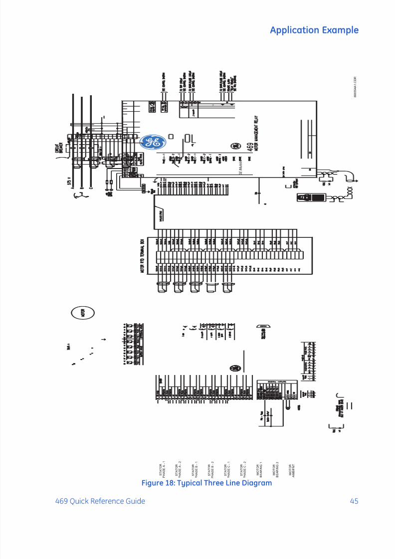
Figure 18: Typical Three Line Diagram
8 0 6 5 5
4 A 1
. C D R
2 8
M O T O R
B E A R I N G 2
3 6
3 2
3 4
3 5
3 3
3 0
3 1
2 9
S T A T O R
S T A T O R
S T A T O R
M O T O R
B E A R I N G 1
P H A S E C
- 2
P H A S E C
- 1
P H A S E B
- 2
2 0
2 4
2 6
2 7
2 5
2 2
2 3
2 1
1 6
1 8
1 9
1 7
1 5
1 4
1 3
S T A T O R
S T A T O R
S T A T O R
P H A S E B
- 1
P H A S E A
- 2
P H A S E A
- 1
5 9 1 1
1 2
1 0 7 8 6 1 3 4 2
+ C
o m p
- S h l d
C o
m p
S h l d
- + + - S h l d
C o
m p - +
C o
m p
S h l d
S h l d
C o
m p + -
C o
m p
S h l d
- + + - S h l d
C o
m p
C o
m p
S h l d
- + + - S h l d
C o
m p
A M B I E N T
M O T O R
GEMultilin
7/27/2019 GEK-106493C
http://slidepdf.com/reader/full/gek-106493c 50/66
Application Example
46 469 Quick Reference Guide
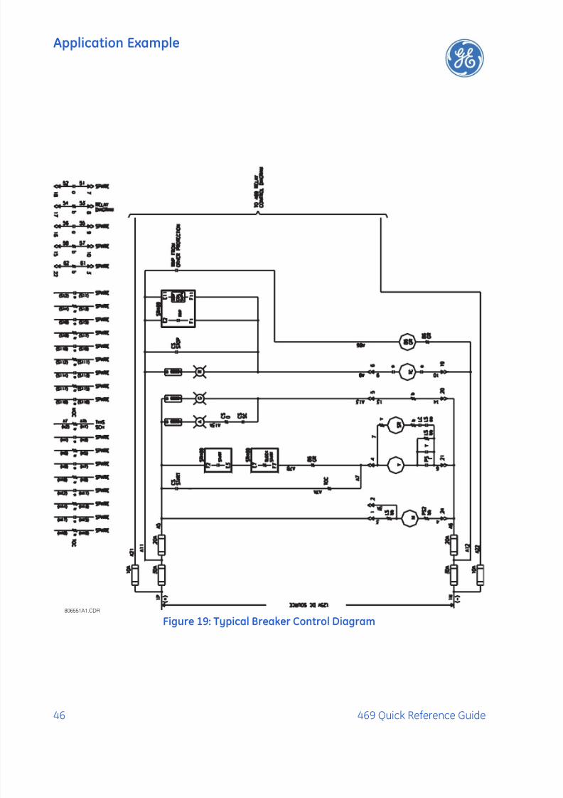
Figure 19: Typical Breaker Control Diagram806551A1.CDR
7/27/2019 GEK-106493C
http://slidepdf.com/reader/full/gek-106493c 51/66
Application Example
469 Quick Reference Guide 47
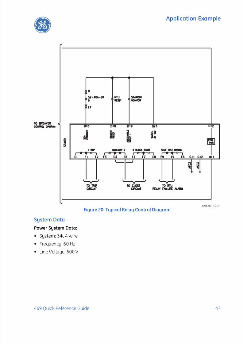
Figure 20: Typical Relay Control Diagram
System Data
Power System Data:
• System: 3Φ, 4 wire
• Frequency: 60 Hz
• Line Voltage: 600 V
806555A1.CDR

7/27/2019 GEK-106493C
http://slidepdf.com/reader/full/gek-106493c 52/66
Application Example
48 469 Quick Reference Guide
Motor Data:
As per the following motor data sheet information:
7/27/2019 GEK-106493C
http://slidepdf.com/reader/full/gek-106493c 53/66
Application Example
469 Quick Reference Guide 49
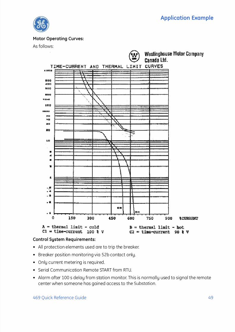
Motor Operating Curves:
As follows:
Control System Requirements:
• All protection elements used are to trip the breaker.
• Breaker position monitoring via 52b contact only.
• Only current metering is required.
• Serial Communication Remote START from RTU.
• Alarm after 100 s delay from station monitor. This is normally used to signal the remotecenter when someone has gained access to the Substation.

7/27/2019 GEK-106493C
http://slidepdf.com/reader/full/gek-106493c 54/66
Application Example
50 469 Quick Reference Guide
Contact Outputs:
• Trip and close to breaker control circuit (Trip and Auxiliary2 relays).
• Relay failure alarm to RTU (self-test warning relay, no programming required)
• Alarm contact (setup in General Sw. A for “Station Monitor”)
• No data communications to other equipment.
RTDs
The motor is fitted with the following RTDs:
• RTD Type: 100 Ω Platinum
• 6 Stator RTDs, 2 per phase
• 2 Bearing RTDs
• 1 Ambient RTDThe above data will be used to set the output relays to achieve breaker control by settingdigital inputs for breaker status, remote operations, remote status, and alarm indication.The example assumes that the communications between the station and the MasterControl center will be done by the RTU. Alarms, status indication, and breaker commandswill be hardwired from the relay to the RTU. Similar information could be exchangedbetween the RTU and the relay via an RS485 or RS422 Serial Link using Modbus RTUprotocol. Refer to GE Publication GEK-106491: 469 Communications Guide for additional
information.
Instrument Transformer DataVoltage Transformers:
3 × Delta connected, ratio = 600:120 V
Motor System Voltage = 575 V
Phase CTs:
The phase CT should be chosen such that the FLC is 50% to 100% of CT primary. Since theFLC is 347.5A a 350:5 or 400:5 CT may be chosen; 400:5 is a standard available size and sowould probably be selected.
Ground CT:For high resistive grounded systems, sensitive ground detection is possible with the50:0.025 CT. On solidly grounded or low resistive grounded systems where the fault currentis much higher, a 1A or 5A secondary CT should be used. If residual connection is used,pickup levels and timers must be set with respect to the acceleration time. The chosen zerosequence CT needs to be able to handle all potential fault levels without saturating. In thisexample, 50:5A CT is selected.
Motor FLC:
Set the Motor Full Load Current to 348A, as specified by the data sheets.

7/27/2019 GEK-106493C
http://slidepdf.com/reader/full/gek-106493c 55/66
Application Example
469 Quick Reference Guide 51
The above data will be used to set the relay System Parameters, such as CT and VTconnections, VT secondary voltage, and CT and VT primary to secondary ratios.
Motor Protection
Overload Pickup:
The overload pickup is set to the maximum allowed by the service factor of the motor. Sincethis motor has RTDs and the relay will be using the RTD bias feature for enhancedprotection. In this case, it would be set to the highest setting of 1.25 x FLC for the motorservice factor of 1.15. If service factor is unknown we must assume 1.0.
Overload Curve:
The standard overload curve to be just below the cold thermal limit to give maximumprocess uptime, without compromising protection. The best fitting curve is curve 7.
Short Circuit Trip:The short circuit trip should be set above the maximum locked rotor current but below theshort circuit current of the fuses. The data sheets indicate a maximum locked rotor currentof 630% FLC or 6.3 x FLC. A setting of 7 x FLC with an instantaneous time delay will be idealbut nuisance tripping may result due to the asymmetrical starting currents and DC offset. Ifasymmetrical starting currents limits the starting capability, set the S/C level higher to amaximum of 11 x FLC to override this condition (1.7x6.3=11.7 where 1.7 is the maximum DC
offset for an asymmetrical current).
Ground Fault:
Unfortunately, there is not enough information to determine a ground fault setting. Thesesettings depend on the following information:
1. The Ground Fault current available.
2. System Grounding - For example high resistive grounding, or solidly grounded.
3. Ground Fault CT used.
4. Ground Fault connection, which could be zero sequence or Residual connection.
For the purpose of this example, we will assume a fault current of 10 Amps or 10/50 = 0.2 xCT, no intentional time delay.
Unbalance Alarm and Trip:The unbalance settings are determined by examining the motor application and motordesign. The heating effect of unbalance will be protected by enabling unbalance input tothermal memory; described in details in Chapter 5, Thermal Model. A setting of 10% for theUnbalance Alarm with a delay of 10 seconds would be appropriate and the trip can be setto 20% with a delay of 5 seconds.
7/27/2019 GEK-106493C
http://slidepdf.com/reader/full/gek-106493c 56/66
Application Example
52 469 Quick Reference Guide
Stopped and Running Cool Times:
The motor manufacturer usually supplies this information as either cooling times, orcooling time constants. In this case they are not part of the data that was given with this
motor. Since RTDs are present and will be wired to the relay, biasing of the thermal modelwill be used so it is not critical to have these cooling times from the manufacturer. Thedefault values of motor cooling time constants are 15 and 30 minutes, and can be used forthe running and stopped cool times respectively. If the manufacturer provides coolingtimes instead, the approximate values of the cooling time constants is 1/5 the cooling timesprovided by the manufacturer.
Acceleration Trip:
This setpoint should be set higher than the maximum starting time to avoid nuisancetripping when the voltage is lower or for varying loads during acceleration. If reduced
voltage starting is used, according to the acceleration curves, a setting of 18 seconds wouldbe appropriate, or if across the line starting is used, a setting of 13 seconds would beappropriate.
Enable Start Inhibit:
This function will limit starts when the motor is already hot. The relay learns the amount ofthermal capacity used at start. If the motor is hot, thus having some thermal capacity used,the relay will not allow a start if the available thermal capacity is less than the required
thermal capacity for a start.
Starts/Hour:
Starts/Hour can be set to the # of cold starts as per the data sheet. For this example, it is notgiven.
Time Between Starts:
In some cases, the motor manufacturer will specify the time between motor starts. In this
example, this information is not given so this feature can be disabled. However, if theinformation is given, the time provided on the motor data sheets should be programmed.
Stator RTDs:
RTD trip level should be set at or below the maximum temperature rating of the insulation.This example has a class F insulation which has a temperature rating of 155°C, therefore
the Stator RTD Trip level should be set to between 140°C to 155°C, with 155°C beingmaximum. The RTD alarm level should be set to a level to provide a warning that the motortemperature is rising. For this example, 135°C would be appropriate since this motor isdesigned for class B rise, 130°C is it's normal hot operating temperature.
Bearing RTDs:
The Bearing RTD alarm and trip settings will be determined by evaluating the temperaturespecification from the bearing manufacturer.

7/27/2019 GEK-106493C
http://slidepdf.com/reader/full/gek-106493c 57/66
Application Example
469 Quick Reference Guide 53
Unbalance Bias Of Thermal Capacity:
Enable the Unbalance Bias of Thermal Capacity so that the heating effect of unbalancecurrents is added to the Thermal Capacity Used.
Unbalance Bias K Factor:
The K value is used to calculate the contribution of the negative-sequence current flowingin the rotor due to unbalance. It is defined as:
(EQ 1)
where: Rr 2 = rotor negative-sequence resistance and Rr 1 = rotor positive-sequenceresistance.
A formula based on empirical data states that K is equal to 230 divided by the per-unit
locked rotor current squared.From the data sheet, the locked rotor amps = 631% FLA or 6.31 × FLA. Therefore,
(EQ 2)
Hot/Cold Curve Ratio:
The hot/cold curve ratio is calculated by simply dividing the hot safe stall time by the coldsafe stall time or use the motor thermal limits curve. For this example, both are available.Using the data sheets the, safe stall time H/C or Hot/Cold Curve Ratio is given as 16/18 =
0.89Enable RTD Biasing:
This will enable the temperature from the Stator RTD sensors, to be included in the
calculations of Thermal Capacity. This model determines the Thermal Capacity Used basedon the temperature of the Stator and is separate from the overload model for calculatingThermal Capacity Used. RTD biasing is a back up protection element, which accounts forsuch things as loss of cooling or unusually high ambient temperature. This measuredtemperature is used to bias or modify the thermal capacity value stored in the relay.
RTD Bias Minimum:
Set to 40°C, which is the ambient temperature, obtained from the data sheets.RTD Bias Mid Point:
The center point temperature is set to the motor's hot running temperature and iscalculated as follows:
Temperature Rise of Stator + Ambient Temperature.
The temperature rise of the stator is 80°C + 10% hot spot allowance, obtained from the datasheets. Therefore, the RTD Center point temperature is set to 90°C + 40°C or 130°C.
K R r 2R r 1--------=
K 230
(per-unit locked rotor amps)2
----------------------------------------------------------------------------
230
6.31----------- 6≈= =

7/27/2019 GEK-106493C
http://slidepdf.com/reader/full/gek-106493c 58/66
Application Example
54 469 Quick Reference Guide
RTD Bias Maximum:
This setpoint is set to the rating of the insulation or slightly less. A class F insulation is usedin this motor that is rated at 155°C, so setting should be 155.
You should now be familiar with maneuvering through and editing setpoint messages. Assuch, we will now limit our discussion to just the values that must be programmed, in orderto meet the requirements of the example application. Any setpoints not explicitlymentioned should be left at the factory default value.
System Setpoints
The S2 setpoints page contains setpoints for entering the characteristics of the equipmenton the motor electrical system. In our example, these characteristics are specified underthe Power System Data and Instrument Transformer Data headings in the previous sub-section. From this information and the resulting calculations, program the page S2
setpoints as indicated.
For current transformers, make the following change in the S2 SYSTEM SETUP CURRENT
SENSING setpoints page:
PHASE CT PRIMARY: “400 A”MOTOR FULL LOAD AMPS FLA: “348 A”GROUND CT: “5 A Secondary”
806550A1.CDR

7/27/2019 GEK-106493C
http://slidepdf.com/reader/full/gek-106493c 59/66
Application Example
469 Quick Reference Guide 55
GROUND CT PRIMARY: “50 A”PHASE DIFFERENTIAL CT: “None”ENABLE 2-SPEED MOTOR PROTECTION: “No”
For current transformers, make the following change in the S2 SYSTEM SETUP VOLTAGE SENSING setpoints page:
VT CONNECTION TYPE: “Open Delta”ENABLE SINGLE VT OPERATION: “Off”VOLTAGE TRANSFORMER RATIO: “5 : 1”
(for a 600 V system, 600/120 V = 5, where 5 is the VT ratio)MOTOR NAMEPLATE VOLTAGE: “575 V”
The 469 Motor Management Relay was designed with the ability to display primary systemvalues. Current and voltage measurements are performed at secondary levels, which the
relay transforms to primary values using CT and VT ratios, system voltage, as well as thenominal secondary values.
In the case of the phase CTs, configuring the relay for current measurements is simple andit only requires inputting the CT primary current. Phase CT inputs can be 1 A or 5 A, andthey must be specified when the relay is purchased.
There is more flexibility with regards to Ground CT inputs, as well as VT inputs, wherenominal values are not required ahead of time, before the relay is ordered; therefore more
settings are needed to set the relay for measurements.
Make the following change in the S2 SYSTEM SETUP POWER SYSTEM setpoints page to
reflect the power system:NOMINAL SYSTEM FREQUENCY: “60 Hz”SYSTEM PHASE SEQUENCE: “ABC”
The example calls for remote control via serial communications, received from the masterstation, through the RTU. Motor starting and stopping is possible via any of the three 469communication ports.
When a start command is issued, the auxiliary relay assigned for starting control isactivated for 1 second to complete the close coil circuit for a breaker application, orcomplete the start control circuit for a contactor application. A contactor sealing contact
would be used to maintain the circuit. For details on issuing a start or stop command viacommunications, refer to the GE Publication GEK-106491: 469 Communications Guide.
Make the following changes to the communications settings in the S2 SYSTEM SETUP
SERIAL COMM. CONTROL page.
SERIAL COMMUNICATION CONTROL: “On”ASSIGN START CONTROL RELAYS: “Auxiliary2”
The Auxiliary 2 relay will be used to start the motor. Note that this auxiliary relay can not beused for any other application.

7/27/2019 GEK-106493C
http://slidepdf.com/reader/full/gek-106493c 60/66
Application Example
56 469 Quick Reference Guide
Once the signal is received the motor will be started across the l ine. Therefore, the followingsetpoints are left with their default values. In the S2 SYSTEM SETUP REDUCE VOLTAGE
STARTING setpoints page:
REDUCE VOLTAGE STARTING: “Off”ASSIGN CONTROL RELAYS: “Auxiliary3” (available for other use)TRANSITION ON: “Current Only”ASSIGN TRIP RELAYS: “Trip”REDUCE VOLTAGE START LEVEL: “100% FLA”REDUCE VOLTAGE START TIMER: “200 s”
Digital Inputs Setpoints
The S3 setpoints page is for entering the characteristics of the digital inputs. In our example,these characteristics are specified under the Control System Requirements heading.
Program the S3 setpoints as indicated.
Some of the functions assigned to the digital inputs of the 469 Motor Management Relayare pre-defined functions, which can be selected from a list . There are four user-definedfunctions, called General Switch A to D, associated to the assignable inputs. Set these inputsto operate output relays, with or without delay, responding to the status change of drycontacts connected to the digital input terminals. Use the following procedure to set thesefunctions:
1. Change the default names to meaningful values so they can be easily identified, eithervia the LCD or when reviewing event reports.
2. Identify their asserted logic.
3. Define the functionality of the digital inputs.
All the other assignable input functions are pre-defined, and when selected, they can be setto generate Trip or Alarms, as well as to energize auxiliary outputs as needed.
For breaker position monitoring, set the following pre-defined Digital Input called “StarterStatus”. As per the information provided above, a 52b contact will be used, and must beconnected between terminals D16 to D23:
S3 DIGITAL INPUTS STARTER STATUS STARTER STATUS SW: “Starter Auxiliary b”
To set the relay to monitor access to the station, use Assignable Input 1 as “General SwitchA”, as follows. To define the digital input, enter the following data in the S3 DIGITAL INPUTS
ASSIGNABLE INPUT 1 setpoints page.
To identify the digital input:
INPUT 1 FUNCTION: “General Sw. A”SWITCH NAME: “Stn. Monitor”
To define the asserted logic:
GENERAL SWITCH A: “Normally Open”
To define the functionality:

7/27/2019 GEK-106493C
http://slidepdf.com/reader/full/gek-106493c 61/66
Application Example
469 Quick Reference Guide 57
BLOCK INPUT FROM START: “0 s”GENERAL SWITCH A ALARM: “Latched”ASSIGN ALARM RELAYS: “Alarm”
GENERAL SWITCH A ALARM DELAY: “5.0 s”GENERAL SWITCH A EVENTS: “On” so this event is registered.GENERAL SWITCH A TRIP: “Off”
If the relay will not be used to trip the motor when someone gain unauthorized access tothe station, the next setpoints shall be left with their default values:
GENERAL SWITCH A TRIP: “Off”ASSIGN TRIP RELAYS: “Trip”GENERAL SWITCH A TRIM DELAY: “5.0 s”
Thermal Model Setpoints
The S5 Thermal Model setpoints page contains setpoints for entering settings related toprotection of the motor during the starting process as well as during normal operation.
As per the information provided above, the settings for the Thermal Model are entered as
follows in the
• SELECT CURVE STYLE: “Standard”OVERLOAD PICKUP: “1.25 x FLA”ASSIGN TRIP RELAYS: “Trip”UNBALANCE BIAS K FACTOR: “6”COOL TIME CONSTANT RUNNING: “15 min.”
COOL TIME CONSTANT STOPPED: “30 min.”HOT/COLD SAFE STALL RATIO: “0.89”ENABLE RTD BIASING: “Yes”RTD BIAS MINIMUM: “40°C” – ambient temperatureRTD BIAS CENTER POINT: “130°C” – center valueRTD BIAS MAXIMUM: “155°C” – maximum valueTHERMAL CAPACITY ALARM: “Unlatched” – recommended for early warning to takecorrective actions and prevent the interruption of the process.ASSIGN ALARM RELAYS: “Alarm” – the Alarm contact could be use for local indication,or to send a local signal to reduce load, before a trip is issued.
THERMAL CAP. ALARM LEVEL: “80%”THERMAL CAPACITY ALARM EVENT: “Yes” – captures event in the event report.
As well, select the overload curve for the Thermal model with the following setpoint in theS5 THERMAL MODEL OVERLOAD CURVE SETUP menu:
STANDARD OVERLOAD CURVE NUMBER: “7”

7/27/2019 GEK-106493C
http://slidepdf.com/reader/full/gek-106493c 62/66
Application Example
58 469 Quick Reference Guide
Current Elements Setpoints
The S6 Current Elements setpoints page contains setpoints for entering protection elementcharacteristics. In our example, these characteristics are specified under Motor Protection
heading.
From this data and the resulting calculations, program the S6 setpoints page as indicated.When setting the relay for the first time, other setpoints not listed in this example should beleft disabled.
For the Short Circuit element , enter the following values in the S6 CURRENT ELEMENTS
SHORT CIRCUIT TRIP page. Press the MESSAGE key after each setpoint is entered tomove to the next message.
SHORT CIRCUIT TRIP: “Latched”SHORT CIRCUIT TRIP OVEREACH FILETER: “Off” - no filtering of DC component is
requiredASSIGN TRIP RELAYS: “Trip”SHORT CIRCUIT TRIP PICKUP: “11.7”INTENTIONAL S/C TRIP DELAY: “0 ms” - Instantaneous trip is required.SHORT CIRCUIT TRIP BACKUP: “On” - if the main disconnect device does not respond tothe trip command, a second signal will be initiated via an auxiliary relay to generate abus shot down; in most cases, the second trip command energizes a lock out relay (86)which is used to trip the upstream breakersASSIGN BACKUP RELAYS: “Auxiliary3”SHORT CIRCUIT TRIP BACKUP DELAY: “200 ms” - this time must be greater than the
total time required to trip the main breaker plus a margin
Since the specifications do not indicate values for the following features, they must be left“Off”:
OVERLOAD ALARM: “Off”MECHANICAL JAM: “Off”UNDERCURRENT: “Off”PHASE DIFFERENTIAL: “Off”
For the Ground Fault element, enter the following values in the S6 CURRENT ELEMENTS
GROUND FAULT page. Press the MESSAGE key after each setpoint is entered to
move to the next message.
GROUND FAULT OVERREACH FILETER: “Off” – no filtering of DC component is requiredGROUND FAULT ALARM: “Off” – default setting, no Alarm is requiredASSIGN ALARM RELAYS: “Alarm” – default settingGROUND FAULT ALARM PICKUP: “0.10 x CT” – default settingINTENTIONAL GF ALARM DELAY: “0 ms” – default settingGROUND FAULT ALARM EVENTS: “Off” – default settingGROUND FAULT TRIP: “Latched” – the output relay will remind energized until the Resetcommand executed

7/27/2019 GEK-106493C
http://slidepdf.com/reader/full/gek-106493c 63/66
Application Example
469 Quick Reference Guide 59
ASSIGN TRIP RELAYS: “Trip”GROUND FAULT TRIP PICKUP: “0.20 x CT”INTENTIONAL GF TRIP DELAY: “0 ms”
GROUND FAULT TRIP BACKUP: “On”ASSIGN BACKUP RELAYS: “Auxiliary3” - same relay assigned for the Short Circuit TripBackupGROUND FAULT TRIP BACKUP DELAY: “200 ms” - same time delay assigned to the ShortCircuit Trip Backup
For the Current Unbalance element, enter the following values in the S6 CURRENT
ELEMENTS CURRENT UNBALANCE page. Press the MESSAGE key after each setpointis entered to move to the next message.
CURRENT UNBALANCE ALARM: “Unlatched”ASSIGN ALARM RELAYS: “Alarm”CURRENT UNBALANCE ALARM PICKUP: “10%”CURRENT UNBALANCE ALARM DELAY: “10 s”CURRENT UNBALANCE ALARM EVENTS: “On”CURRENT UNBALANCE TRIP: “Latched” – the output relay will remind energized untilthe Reset command executedASSIGN TRIP RELAYS: “Trip”CURRENT UNBALANCE TRIP PICKUP: “20%”CURRENT UNBALANCE TRIP DELAY: “5 s”
Motor Starting Setpoints
The S7 Motor Starting setpoints page contains additional setpoints used to complement theThermal Model. In our example, these characteristics are specified under Motor Protectionheading.
For the Acceleration Timer element, enter the following values in the S7 MOTOR STARTING
ACCELERATION TIMER page. Press the MESSAGE key after each setpoint is completedto move to the next message.
ACCELERATION TIMER TRIP: “Latched”ASSIGN TRIP RELAYS: “Trip”ACCELERATION TIMER FROM START: “13 s” – as shown in the acceleration curves at
100% voltage
For the Start Inhibit element, enter the following values in the S7 MOTOR STARTING
START INHIBIT page. Press the MESSAGE key after each setpoint is completed to move tothe next message.
START INHIBIT BLOCK: “On”TC USED MARGIN: “25%”
With these settings, the 469 relay prevents motor starting if there is insufficient thermalcapacity for a successful motor start.

7/27/2019 GEK-106493C
http://slidepdf.com/reader/full/gek-106493c 64/66
Application Example
60 469 Quick Reference Guide
There is not information available to set Starts/Hour, T ime Between Starts, or the RestartBlock features. Therefore, the following setpoints must be disabled:
JOGGING BLOCK: “Off”
RESTART BLOCK: “Off”
RTD Temperature Setpoints
The S8 RTD Temperature page contains the setpoints for the twelve (12) field programmableRTDs that are normally used for temperature monitoring. The temperature measured byeach RTD can be compared to pickup values, and set to energize Trip or Alarm outputs.
For proper temperature monitoring, enter the RTD types in the S8 RTD TEMPERTURE RTD
TYPES page. Press the MESSAGE key after each setpoint is completed to move to the next
message.
STATOR RTD TYPE: “100 Ohm Platinum”BEARING RTD TYPE: “100 Ohm Platinum”AMBIENT RTD TYPE: “100 Ohm Platinum”OTHER RTD TYPE: “100 Ohm Platinum” – default value
As per the information provided above, there will be six RTDs, two per phase located in theStator, and two Bearing RTDs, one to monitor the ambient temperature.
For Stator Overtemperature protection, enter the following setpoints in the S8 RTD
TEMPERTURE RTD 1 to RTD6 menus:
RTD #1 APPLICATION: “Stator”
RTD #1 NAME: “ST Ph A1”RTD #1 ALARM: “Unlatched”ASSIGN ALARM RELAYS: “Alarm”RTD #1 ALARM TEMPERATURE: “135°C”RTD #1 HIGH ALARM: “Off”HIGH ALARM RELAYS: “Alarm” - default valueRTD #1 HIGH ALARM TEMPERATURE: “135°C” - default valueRTD #1 ALARM EVENTS: “On”RTD #1 TRIP: “Latched”RTD #1 TRIP VOTING: “RTD #5”
ASSIGN TRIP RELAYS: “Trip”RTD #1 TRIP TEMPERATURE: “155°C”
The settings for the other RTDs are entered in similar fashion.
Undervoltage Protection:
In addition to the settings illustrated above, there will be cases in motor applications whereadditional settings will be required, to monitor other system parameters such as voltagelevels.
The following sub-section will illustrate the procedures to set the 469 Motor ManagementRelay to meet those requirements.

7/27/2019 GEK-106493C
http://slidepdf.com/reader/full/gek-106493c 65/66
Application Example
469 Quick Reference Guide 61
Using the same system information, the following example illustrates the steps to set the469 for Undervoltage protection.
The following setpoints are provided:
Pickup: 70% of nominal voltage – starting80% of nominal voltage – running
Time Delay: 13.0 s
Other Considerations:
• The function will be active only if there is voltage in the line feeding the motor, to avoidnuisance trips due to the lack of voltage. The 469 will consider the bus energized only ifthe measured voltage is greater than 20% of nominal voltage. A trip condition will beinitiated only if undervoltage is detected in all the phases.
• In order to monitor for VT Fuse Failure or to monitor for undervoltage in one phase only,set an Alarm when the voltage is 90% of nominal voltage both during start and running.
For the Undervoltage element, enter the following values in the S9 VOLTAGE ELEMENTS
UNDERVOLTAGE setpoints page. Press the ENTER key to save, and then the MESSAGE key, after each setpoint is completed, to move to the next message:
U/V ACTIVE ONLY IF BUS ENERGIZED: “Yes”UNDERVOLTAGE ALARM: “Unlatched”ASSIGN ALARM RELAYS: “Alarm”UNDERVOLTAGE ALARM PICKUP: “0.9 x RATED”STARTING U/V ALARM PICKUP: “0.9 x RATED”
UNDERVOLTAGE ALARM DELAY: “0.0 s”UNDERVOLTAGE ALARM EVENTS: “Yes”UNDERVOLTAGE TRIP: “Latched”UNDRVOLTAGE TRIP MODE: “3-Phase”ASSIGN TRIP RELAYS: “Trip”UNDERVOLTAGE TRIP PICKUP: “0.8 x RATED”STARTING U/V TRIP PICKUP: “0.7 x RATED”UNDERVOLTAGE TRIP DELAY: “13.0 s”
Installation:
Now that programming for the sample application is complete, the relay should be in theService state. Note that the relay is defaulted to the Not Ready state when it leaves thefactory. A minor self-test warning message informs the user that the 469 MotorManagement Relay has not yet been programmed. If this warning is ignored, protection willbe active, using factory default setpoints. The Relay In Service LED Indicator will be on.
By now, once you have completed all the steps illustrated on this typical example, youshould be able to set the GE Multilin 469 Motor Management relay for a typical feederapplication.

7/27/2019 GEK-106493C
http://slidepdf.com/reader/full/gek-106493c 66/66
Application Example
For further technical support, and additional documentation on this, and other GE Multilinproducts, please contact us at:
215 Anderson Avenue
Markham, Ontario L6E 1B3Canada
Telephone: (905) 294-6222Fax: (905) 201-2098E-mail: [email protected]: http://www.GEmultilin.com