high-rise testing of drainage system on two of the...
TRANSCRIPT

High-Rise Testing of Drainage System on Two of the World’s Tallest Test Towers 在世界上两座最高的测试塔测试高层排水系
统 Steven White, Technical Director, Studor Ltd Steven White,技术总监,思都得有限公司

• Tall buildings are using 21st century cutting edge research and design tools, for the buildings architecture, structural design and buildings services
• The one building service that is still way behind the other disciplines, being the above ground drainage system.
• It is fundamentally based on late 19th and early 20th century calculations and practises, used in many national building codes today.
© Council on Tall Buildings
and Urban Habitat

• Research and product innovations have only been developed in the late 20th and early 21st century that meet the demands of modern high-rise buildings in above ground drainage.
• . The conservative nature of the discipline and the reliance on national codes as being fit for purpose, sometimes leads to the engineers to disregards the findings of the research and the use of innovative products that will ensure that the drainage system will function correctly.
© Council on Tall Buildings
and Urban Habitat

Why do we use siphons?
The drainage system is one of the few building systems that is integrated throughout the
building.
Water trap seals are commonly used to
provide a barrier between the drainage
system and the living space.
What mostly affects water trap seals?
• Pressure fluctuations: self siphonage,
induced siphonage, positive pressure
and wind effect;
• Thermal depletion.
Siphons
© Council on Tall Buildings
and Urban Habitat

Pressure fluctuations
Siphonage: starts to occur when the pressure at that point in the system exceeds -40mmWg (-400Pa)
Positive pressure: air bubbles start to go through when the pressure at that point in the system exceeds -40mmWg (+400Pa)
© Council on Tall Buildings
and Urban Habitat

Solution: criteria
The solution is to balance the pressure in the drainage system.
How? bringing enough air
When? as quickly as possible
Where? at the point of need
© Council on Tall Buildings
and Urban Habitat
• The development of active drainage ventilation has always been focused on high-rise drainage systems and has been developed from a research basis into a commercialised system.
• Active Drainage Ventilation, the combination of AAV’s and the P.A.P.A™ working together to help balance the positive and negative transients generated in the drainage system from reaching levels that breach or siphon water trap seals (-+400Pa.).
• The use of simulation/modelling has been essential to the development of the active drainage ventilation solution and by using AIRNET developed by Heriot Watt University.
© Council on Tall Buildings
and Urban Habitat

Trap response to pressure fluctuations
Trap A
Stack A Stack B Stack C
Trap BTrap C
50-storey building with 150mm wet stacks and 100mm vent pipe network
Case study 2 – Distributed venting using AAVs
Stack A
Stack B Stack C
150 mm Vertical stack
150 mm collection drain
Active Zone A
Active Zone B
Active Zone C
Surcharge simulated here
P.A.P.A.TM
50-storey building with 150mm stack with a loading of 6.5l/s utilising AAVs and P.A.P.A.
Trap response to pressure fluctuations
Trap A
Stack A Stack B Stack C
Trap BTrap C
50-storey building with 150mm wet stacks and 100mm vent pipe network
Trap response to pressure fluctuations
Stack A Stack B Stack C
Active Zone B
Active Zone A
Trap A
Trap B
Trap C
Vertical Stack
diameter 150 mm
50-storey building with 150mm wet vent stack and AAVs placed at the point of need in the system
Trap A
Trap B
Trap C
Water Retained Trap A = 46 mm
Trap B2 = 44.5 mm
Trap C = 0 mm
Trap response to pressure fluctuations
-50
-30
-10
10
30
50
0 10 20 30 40Time (s)
Trap
dep
th (m
m) Trap A appliance side
Trap A system side
-50
-30
-10
10
30
50
0 10 20 30 40Time (s)
Trap
dep
th (m
m) Trap B appliance side
Trap B system side
-50
-30
-10
10
30
50
0 10 20 30 40Time (s)
Trap
dep
th (m
m) Trap C appliance side
Trap C system side
Trap blown
Results of the trap seals when subjected to a discharge of 12.4l/s over a 35 second period
50-storey comparison of venting options under positive and negative pressures using AIRNET carried out under funding by Studor
Active air pressure transient control
-50
-30
-10
10
30
50
0 2 4 6 8 10Time (s)
Trap
dep
th (m
m) Trap A1 appliance side
Trap A1 system side
Trap A
Trap B
Trap C
Water Retained Trap A1 = 46.5 mm
Trap B2 = 42.6 mm
Trap C3 = 48.5 mm
Trap response to pressure fluctuations
-50
-30
-10
10
30
50
0 10 20 30 40Time (s)
Trap
dep
th (m
m) Trap B appliance side
Trap B system side
-50
-30
-10
10
30
50
0 10 20 30 40Time (s)
Trap
dep
th (m
m) Trap C appliance side
Trap C system side
Results of the trap seals when subjected to a discharge of 12.4l/s over a 35 second period
Trap A
Trap B
Trap C
Water Retained Trap A = 46 mm
Trap B2 = 44.5 mm
Trap C = 0 mm
Trap response to pressure fluctuations
-50
-30
-10
10
30
50
0 10 20 30 40Time (s)
Trap
dep
th (m
m) Trap A appliance side
Trap A system side
-50
-30
-10
10
30
50
0 10 20 30 40Time (s)
Trap
dep
th (m
m) Trap C appliance side
Trap C system side
-50
-30
-10
10
30
50
0 10 20 30 40Time (s)
Trap
dep
th (m
m) Trap B appliance side
Trap B system side
Results of the trap seals when subjected to a discharge of 6.5l/s over a 35 sec. period and a surcharge placed downstream after a 30 sec. period with the load at that point of 3.5l/s
Trap A
Trap B
Trap C
Water Retained Trap A = 46 mm
Trap B2 = 42 mm
Trap C = 43 mm
Trap response to pressure fluctuations
-50
-30
-10
10
30
50
0 10 20 30 40Time (s)
Trap
dep
th (m
m) Trap A appliance side
Trap A system side
-50
-30
-10
10
30
50
0 10 20 30 40Time (s)
Trap
dep
th (m
m) Trap B appliance side
Trap B system side
-50
-30
-10
10
30
50
0 10 20 30 40Time (s)
Trap
dep
th (m
m) Trap C appliance side
Trap C system side
Results of the trap seals when subjected to a discharge of 6.5l/s over a 35 sec. period and a surcharge placed down stream after a 30 sec. period
© Council on Tall Buildings
and Urban Habitat
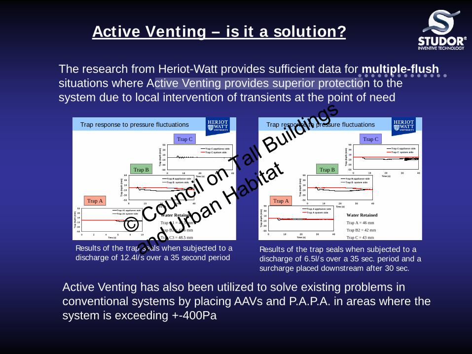
Active Venting has also been utilized to solve existing problems in conventional systems by placing AAVs and P.A.P.A. in areas where the system is exceeding +-400Pa
The research from Heriot-Watt provides sufficient data for multiple-flush situations where Active Venting provides superior protection to the system due to local intervention of transients at the point of need
Active Venting – is it a solution?
-50
-30
-10
10
30
50
0 2 4 6 8 10Time (s)
Trap
dep
th (m
m) Trap A1 appliance side
Trap A1 system side
Trap A
Trap B
Trap C
Water Retained Trap A1 = 46.5 mm
Trap B2 = 42.6 mm
Trap C3 = 48.5 mm
Trap response to pressure fluctuations
-50
-30
-10
10
30
50
0 10 20 30 40Time (s)
Trap
dep
th (m
m) Trap B appliance side
Trap B system side
-50
-30
-10
10
30
50
0 10 20 30 40Time (s)
Trap
dep
th (m
m) Trap C appliance side
Trap C system side
Results of the trap seals when subjected to a discharge of 12.4l/s over a 35 second period
Trap A
Trap B
Trap C
Water Retained Trap A = 46 mm
Trap B2 = 42 mm
Trap C = 43 mm
Trap response to pressure fluctuations
-50
-30
-10
10
30
50
0 10 20 30 40Time (s)
Trap
dep
th (m
m) Trap A appliance side
Trap A system side
-50
-30
-10
10
30
50
0 10 20 30 40Time (s)
Trap
dep
th (m
m) Trap B appliance side
Trap B system side
-50
-30
-10
10
30
50
0 10 20 30 40Time (s)
Trap
dep
th (m
m) Trap C appliance side
Trap C system side
Results of the trap seals when subjected to a discharge of 6.5l/s over a 35 sec. period and a surcharge placed downstream after 30 sec.
© Council on Tall Buildings
and Urban Habitat

Academicals research & comparisons
© Council on Tall Buildings
and Urban Habitat

• The new building demands in London UK, with over 230 high-rise buildings being constructed over the next 5 years ranging from 20 floors up to 80 floors or more, and with floor space costing $472-$4720 USD ft².
• Major building firms are looking at new solutions to maximise sellable space within these buildings.
• One of the largest builders in the UK, UAE and Australia have a project called Principle Place a 50 floor project in London
• They requested that active drainage ventilation be physically
proven to them outside of the research.
© Council on Tall Buildings
and Urban Habitat

• In China, Studor has been working with local partners for a number of years in developing products standards for AAV’s which was achieved back in 2004
• The Active Drainage Systems for code approval is being sought for in China. Existing data and research has been supplied but it is still a requirement for the code official to have testing within China before approval can be given.
Given the request from major builders and code officials for physical proof that supports the large amount of existing research. Active Drainage Ventilation has been tested on two of the largest test towers
© Council on Tall Buildings
and Urban Habitat
TESTING AIMS
• To compare traditional pipe vented systems designed to national codes to the active drainage ventilation solutions.
• To subject the drainage systems to extreme loadings and usage and
introducing waste into the system that a normal high-rise may be subjected too in every day usage. Keeping to the principle of unsteady state discharges verses steady state discharging as this is the reality of the system in a real building.
• To focus on the trap seal retention during and after discharging into
the system, as this is the main goal of drainage ventilation to ensure that the barrier is maintained.
• Focus on dynamic discharges by using WC as the principle
discharge route into the system.
© Council on Tall Buildings
and Urban Habitat

CHINESE EXPERIMENTAL TEST TOWER
• The testing on this tower has been undertaken by contract between Studor and the China Architecture Design and Research Group CNERC for Human settlement.
• The Chinese experimental test tower in Dongguan, Guangdong, Province operated by the China National Engineering Research Centre for Human Settlements- Vanke Building Research
© Council on Tall Buildings
and Urban Habitat

Water trap seals have been installed throughout the floors, AAV’s and
PAPA™ have been installed with gate valves, so that they can be switched in and switched out as required through
the testing phases
© Council on Tall Buildings
and Urban Habitat
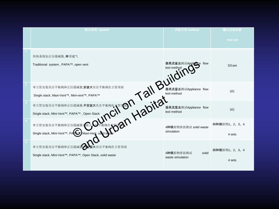
测试系统 system 试验方法 method 建议实验组数
test set
1
传统系统加正压缓减器, 伸顶通气
Traditional system , PAPA™, open vent
器具流量法测试Appliance flow test method
3组set
2 单立管安装负压平衡阀和正压缓减器,安装大负压平衡阀在立管顶部
Single stack, Maxi-Vent™, Mini-vent™, PAPA™
器具流量法测试Appliance flow test method
3组
3 单立管安装负压平衡阀和正压缓减器,不安装大负压平衡阀在立管顶部
Single stack, Mini-Vent™, PAPA™ , Open Stack
器具流量法测试Appliance flow test method
3组
4 单立管安装负压平衡阀和正压缓减器安装大负压平衡阀在立管顶部
Single stack, Mini-Vent™, PAPA™, Maxi-Vent, solid waste
4种模拟物排放测试 solid waste simulation
四种模拟物1、2、3、4
4 sets
5
单立管安装负压平衡阀和正压缓减器,不安装大负压平衡阀在立管顶部
Single stack, Mini-Vent™, PAPA™, Open Stack, solid waste
4种模拟物排放测试 solid waste simulation
四种模拟物1、2、3、4
4 sets
© Council on Tall Buildings
and Urban Habitat

楼层 floor
排水流量测试组合
discharge test set 固体排水测试组合solid waste tests
1 2 3
1 加厕所
纸 Toilet paper
2湿纸巾, wet towel
paper
3卫生巾 sanitary towel
4固体(待通知规
格) solid,TBC
34 x
33 x x x x 只排水water
only x
32 x 31 x 30 x 29 x 28 x 27 x 26 x
25 x
24 x x x 加卫生巾add sanitary towel
x
23 22 x 21 x 20 x 19 x 18 x 17 x 16 x
15 x x x x 只排水 water
only x
14 x 13 x 12 11 10 x
9 x x x x 只排水 water
only x
8 x 7 x 6 x 5 x 4 x 3 x
2 x x x x 只排水 water
only x
1 x
© Council on Tall Buildings
and Urban Habitat

CHINESE EXPERIMENTAL TEST TOWER EXAMPLE, SINGLE TEST RESULT System Description • The two Experimental test of the systems, are using DN110 single
stack pipe. • Traditional signal stack system with open vent to atmosphere • AAV’s installed on each branch, P.A.P.A. ™ installed every 3 floors,
Maxi-Vent™ installed at the top of the stack TEST: • Discharge (christen 6l) at 30-33F, each floor has 1 unit. • Tests are carried out 2 and 4 units discharge at same time to
analyse pressure response.
© Council on Tall Buildings
and Urban Habitat

Result: Under same test configuration, the maximum negative pressure within the Studor system had significantly smaller pressure than the maximum negative value of the traditional single-riser system. In particular with the 4 discharges without the AAV’s the system exceeded -1100Pa and loss of the water trap seal. With the AAV’s the system only went -310Pa and fell within national code limits of -400Pa. In the two discharge test the traditional system exceeded -400Pa with partial loss of the water trap seal but with the AAV’s engaged the system pressure reached -150Pa and the trap seal was maintained.
© Council on Tall Buildings
and Urban Habitat
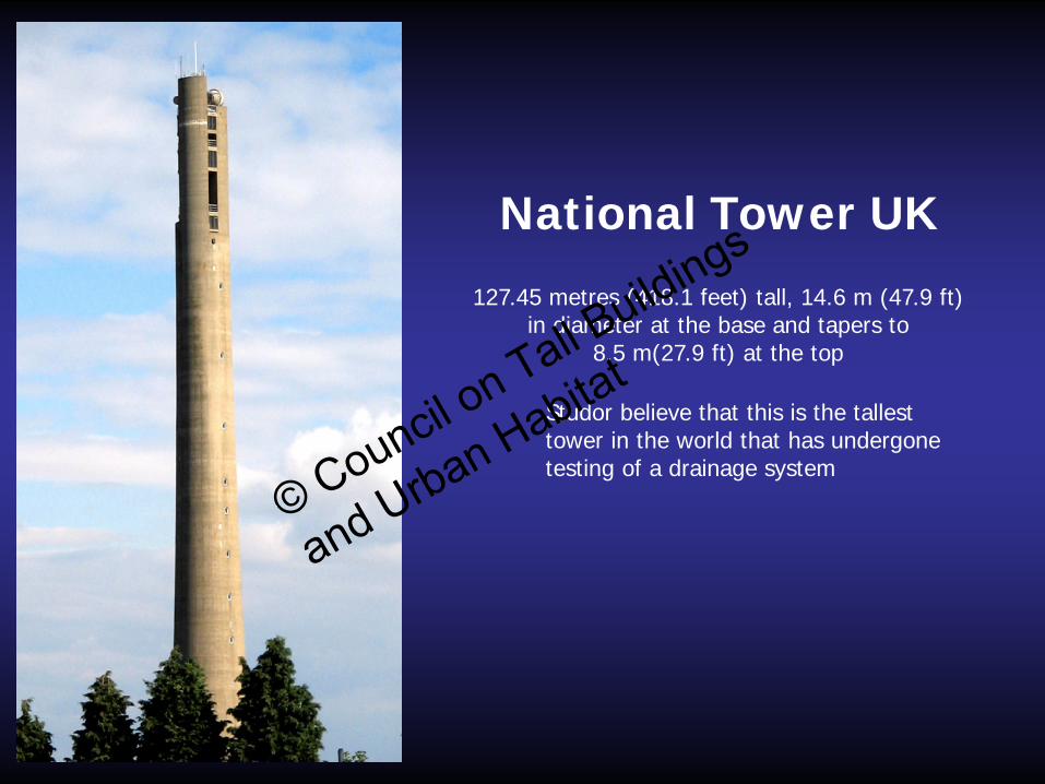
127.45 metres (418.1 feet) tall, 14.6 m (47.9 ft) in diameter at the base and tapers to
8.5 m(27.9 ft) at the top
National Tower UK
Studor believe that this is the tallest tower in the world that has undergone testing of a drainage system
© Council on Tall Buildings
and Urban Habitat

© Council on Tall Buildings
and Urban Habitat

STUDOR Have installed the STUDOR SYSTEM onto the tower
© Council on Tall Buildings
and Urban Habitat

© Council on Tall Buildings
and Urban Habitat

• Studor have undertaken a system testing philosophy to try to reproduce a real drainage system in operation
• Testing has been undertaken with high water discharges over 3-5 locations with up to 60 litres discharged into the system in less than 15 seconds in a 100mm stack
• Testing has been undertaken with solids, wet wipes and sanitary towels
• To measure the response of the system, manometers and Pressure- TEQ as well as video have been used to collect the data.
© Council on Tall Buildings
and Urban Habitat

© Council on Tall Buildings
and Urban Habitat

© Council on Tall Buildings
and Urban Habitat

• This 101-floor building experiences positive transient pressures from floors 6 to 12, evident through bubbling and self siphonage of toilets
Do these designs fail?
• The design for this building covers 8 floors that tie into a centralised stack and vent system of 200 DN pipes
• Local intervention of Active Ventilation was used to resolve the problem
© Council on Tall Buildings
and Urban Habitat

Trump Tower – Panama City – Panama Original drainage system design: fully vented according ASPE/IPC code Cost Savings Installing the Studor System in this mixed used (Hotel + luxurious residential flats) 239m high building, more than 40,000m of equivalent ventilation pipe were saved. In details 36,000m of 2” and 3,400m of 4” ventilation pipes where replaced by 2,200 Studor Mini-Vent, 56 Studor Maxi-Vent and 180 Studor P.A.P.A.’s. The overall saving of kilometers of pipe has reduced drastically the carbon footprint of the drainage system, making the Studor System the “greenest solution”.
© Council on Tall Buildings
and Urban Habitat

Case studies Al Zeina, Abu Dhabi, United Arab Emirates
Arabtec Residential Building, Dubai Silicon Oasis, United Arab Emirates
Ferrari World Abu Dhabi, Yas Island, Abu Dhabi, United Arab Emirates
Ford Field Stadium, Detroit, USA
Greenwich Creekside, London, UK
Hamilton Harbour, Queensland, Australia
Monselice General Hospital (Nuovo Polo Ospedaliero Unico), Italy
Nation Towers, Abu Dhabi, United Arab Emirates
Pak Tin Estate, Hong Kong, China
Social Housing Project, Middle East
The Hub Hotel, Milan, Italy
The O2, Greenwich, London, UK
Trump Ocean Club, Panama City, Panama
Tu Uru Taumatua, The Bay of Plenty, New Zealand
See: www.studor.net
© Council on Tall Buildings
and Urban Habitat

• Complete active control for the drainage system
• Improved performance versus traditional systems
proven by university studies
• Space saving
• Quick and easy installation
• Saves labour and material costs
The Studor System Studor AAVs + Studor® P.A.P.A™
Maxi-Vent™
P.A.P.A.™
Mini-Vent™
Trap-Vent™
© Council on Tall Buildings
and Urban Habitat

With substantial research and the problems solved by Active Venting, it is a logical step to design a high-rise system from the start:
• Reduced system complexity
• Reduced time of installation and labour
• Reduced material used in the system, bringing sustainability to the design
• Increased predictability of the system operation
• Ability to place suppression between transient source and appliances trap seals to be protected
• Interception of transients prior to propagation throughout the network and impact on all connected appliance trap seals
Active Venting – is it a solution?
© Council on Tall Buildings
and Urban Habitat

With Active Venting the drainage system becomes:
• Single stack system
• Suitable for buildings of over 100 floors
• System pressures kept in the region +-100Pa, well below +-400Pa that affect trap seals in the system
Active Venting – is it a solution?
Single stack active vented system
© Council on Tall Buildings
and Urban Habitat

Conclusion
• Increasingly high-rise buildings are being designed across the world
• There are many examples of their drainage systems failing
• Current codes do not address the requirements for high-rise buildings
• Only through dedicated research and validation in the market place can a truly safe systems be designed
• Through a partnership of research and manufacture, new systems can be developed for the requirements of high-rise design
• Active Venting is one such system that has been developed and is proven through research and practise
© Council on Tall Buildings
and Urban Habitat

Thank you!
© Council on Tall Buildings
and Urban Habitat