kerala transformer
TRANSCRIPT

7/27/2019 Kerala Transformer
http://slidepdf.com/reader/full/kerala-transformer 1/18
KERAL ELECTRICALS AND ALLIED
ENGINEEING CO. LTD
TRAINING PERIOD : 25-08-2012
PLACE : KOCHIN, KERALA
Kerala Electricals is fully owned by the Government of Kerala. This company has four
Manufacturing units and the corporate office is in Panampilly Nagar, Kochi. The company is
manufacturing Hi-tech industrial electrical products, viz. Brushless Alternators, Transformers,
HRC Fuses etc. The unit that we visited is Mamala Unit, where transformers are manufactured.
TRANSFORMER
A transformer is a device that transfers electrical energy from one circuit to another
through inductively coupled conductors — the transformer's coils. A varying current in the first
or primary winding creates a varying magnetic flux in the transformer's core and thus avarying magnetic field through the secondary winding. This varying magnetic field induces a
varying electromotive force (EMF), or "voltage", in the secondary winding. This effect is
called mutual induction.
TYPES OF TRANSFORMERS
Step up transformer
The secondary voltage is higher than the primary voltage is known as step up transformer
Step down transformer
The secondary voltage is lower than the primary voltage is known as step down
transformer
Auto Transformer
7/27/2019 Kerala Transformer
http://slidepdf.com/reader/full/kerala-transformer 2/18
An autotransformer is an electrical transformer with only one winding. The auto prefix
refers to the single coil acting on itself rather than any automatic mechanism. In an
autotransformer portions of the same winding act as both the primary and secondary. The
winding has at least three taps where electrical connections are made. An autotransformer can be
smaller, lighter and cheaper than a standard dual-winding transformer however the
autotransformer does not provide electrical isolation. Autotransformers are often used to step up
or down between voltages in the 110-117-120 volt range and voltages in the 220-230-240 volt
range, e.g., to output either 110 or 120V (with taps) from 230V input, allowing equipment from a
100 or 120V region to be used in a 230V region.
PARTS OF TRANSFORMER
1. Transformer tank
2. Breather
3. Conservator
4. Explosion vent
5. Transformer oil
6. Buccholz relay
7. Method of cooling transformer
a) Cooling Methods by Dry Type Transformers
b) Cooling Methods for Oil Immersed Transformers
c) Oil Forced Methods with Heat Exchangers
Transformer Tank
Transformer tanks are tanks used for housing the active part of the transformer which is
immersed in oil tanks are constructions made of welded thin steel sheets basically; there are three
types of transformer tanks
Tank and tank cover jointed with bolted connection: where the tank cover is a flat
plate reinforced with ribs, or where the tank and the tank cover are welded constructions. This
type is adjusted for road transportation on special vehicles or for rail road transportation when it
it placed on a wagon.
7/27/2019 Kerala Transformer
http://slidepdf.com/reader/full/kerala-transformer 3/18
Bell-type tank: has a construction reverse to the version under above the cover is
designed as a bell and the lower part is either a flat plate or a shallow vessel joined with the
cover either with welded or bolted connection. This type is also designed for larger transformer
because it enables opening of a transformer using a crane with a lower load-bearing capacity
Tank for railroad transportation this version of tank is generally used for larger
transformers where dimensions and mass represent a limiting factor for road transportation. This
type of tank requires special reinforcements such as suspensions on the train.
Breather
Breathing is the process where the transformer Breather-In or Breather-out the air from its body
due to thermal contraction & expansion of oil mass. When the transformer is loaded or unloaded,
the oil temperature inside the transformer tank rises or falls accordingly the air pressure inside
the tank changes by either breathing in or breathing out the air. This phenomenon is called
"Breathing" of the transformer. Now, the air which is being breathed in contains either dust
particles and/or humidity that change the dielectric strength of the oil. For proper functioning of
transformer, it is absolutely necessary that dielectric strength of transformer oil remains
unimpaired. Hence, it is necessary that, the air entering into the transformer is free from moisture
& dust particles.
Function of Silica Gel Breather:
The sole function of Silica Gel Breather is to dehydrate (remove moisture) the air & to
remove dust particles of the air breathed in by the transformer.
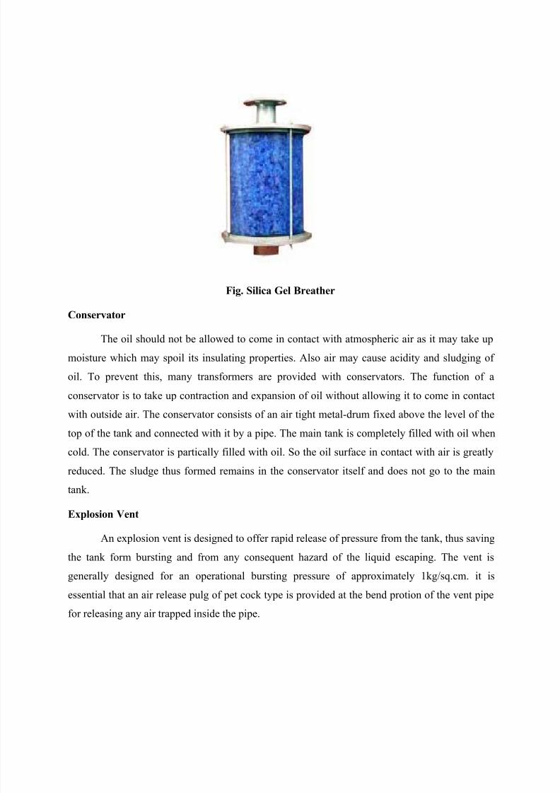
Operation & Working of Silica Gel Breather :
Silica Gel (Air dehydrating) breathers are transparent hollow cylinder tubes which
contain chemically pure silicium salt (Silica Gel) with cobalt indicator. This grade of Silica Gel
is called as ―indicating grade‖ of Silica Gel.

7/27/2019 Kerala Transformer
http://slidepdf.com/reader/full/kerala-transformer 4/18
The indicating grade of Silica Gel, which is filled in the breather, is hard blue crystals, which
has considerable absorption power for moisture. Silica Gel absorbs moisture signaling the
saturation degree by changing color as follows.
Deep Blue Silica Gel completely dry
Light Blue Silica Gel partly humid. (Absorbed water for about 15% of its weight)
Pink Silica Gel saturated with moisture. (Absorbed water for about 30 - 40% of its
weight)
For proper functioning of transformer dehumidification of Silica Gel crystals & removal of
dust particles from breathed air is necessary.
Moisture is removed from Silica Gel crystals by heating it inside a ventilated oven at to 150
C, until the color becomes deep blue again.
Dusts particles are filtered by the oil in the oil cup. Pressure value for air passage into the
breather are: 0.003 Kg/cm inlet or 0.005 Kg/cm outlet.
CRITERIA FOR SELECTING SILICA GEL BREATHER
Keeping in view the above functions of Silica Gel Breather the main criteria for selecting the
breather becomes,
Gel changes color from deep blue to pinkish white as it absorbs moisture. By reheating,
the Gel becomes free from moisture & hence transformer always breathes in dry air.
Visibility of Gel color is very important to decide when to reheat the Gel.
Oil in the oil cup allows dust particles of air to settle in the oil. By changing the oil &
cleaning the oil cup air becomes free from dust particles. Visibility of oil level & dust
particle in the oil cup is very important to decide when to change the oil.
Transformer should breathe from breathing holes (provided in breather) only. If air enters
through any other portion of the breather except breathing holes it is called leakage of air.
Leakage of air will lead to entrance of air with moisture & particles in the transformer,
which ultimately may lead to formation of spark, and short circuit in the transformer.
7/27/2019 Kerala Transformer
http://slidepdf.com/reader/full/kerala-transformer 5/18

7/27/2019 Kerala Transformer
http://slidepdf.com/reader/full/kerala-transformer 6/18
Regarding the diaphragm vent, we should be very particular about its thickness and
material. Some small transformer manufacturers not possessing adequate mechanical knowledge
cannot ascertain the right kind of diaphragm materials.
In some cases, I have the experience of witnessing 3mm thick Perspex sheet being usedas the diaphragm. A few even use 6mm cork sheet as vent material. The correct material for
diaphragm for a power transformer is 1/128 inch (0.02mm) thick Hylum sheet, which almost
breaks at a pressure of 1 kg/sq.cm.
Other materials of equivalent property may also be used as vent materials. Manufacturers
as well as buyers, during their customer’s inspection, must ensure the use of the right kind of
diaphragm material along with its bursting pressure. The check may be done by applying dry air
pressure on a complete transformer filled with oil up the required levels. The diaphragm must
burst at a pre-determined pressure.
Transformer Oil
For both the designer and the user of an oil-filled transformer it can of value to have
some understand if the composition and the properties of the transformer oil and an appreciation
of the ways in which these enable it to perform its dual functions of providing cooling and
insulation within the transformer.
Such an understanding can greatly assist in obtaining optimum performance from the
transformer throughout its operating life.
That is the main purpose of this section. To increase awareness of the role of insulating
oil, which can often be taken somewhat for granted and to help those having dealings with oil-
filled transformers to recognise the important part which the oil plays in the achievement of
satisfactory operation.
Bucholz Relay

7/27/2019 Kerala Transformer
http://slidepdf.com/reader/full/kerala-transformer 7/18
Power Transformers are considered to be a highly reliable type of equipment, yet, in
order to ensure the continuity of service that modern conditions demand, protective devices are
required. The purpose of such devices is to disconnect faulty apparatus before large-scale
damage is caused by a fault to the apparatus or to other connected apparatus. Such devices
generally respond to a change in the current or pressure arising from the faults and are used for
either signaling or tripping the circuits.
Protective devices in the ideal case must be sensitive to all faults, simple in operation,
robust for service and economically feasible. Considering liquid immersed transformers, a near-
ideal 'protective device' is available in the form of Gas and Oil relay described here. The relay
operates on the well-known fact that almost every type of electric fault in a 'liquid immersed
transformer' gives rise to gas. This gas is collected in the body of the relay and is used in some
way or other to cause the alarm or the tripping circuit to operate.
7/27/2019 Kerala Transformer
http://slidepdf.com/reader/full/kerala-transformer 8/18
WORKING
The function of a double element relay will be described here. During normal operation
of a transformer the Buchholz relay is completely filled with oil. Buoyancy and t he moment due
to counterweights keep the floats in their original top positions. In the event of some fault in theinterior of the transformer tank, gas bubbles are produced which accumulate in the Buchholz
relay on the way to the conservator. In consequence, the oil level in the relay enclosure drops
which in turn lowers the upper bucket.
This causes the mercury switch to operate an alarm signal. The lower bucket does not
change its position, because when the gas reaches the upper inside wall of the pipe it can escape
into the conservator. Hence, minor fault in the transformer tank will not trigger the lower
switching assembly and will not trip the transformer. In case the liquid continues to drop due to
loss of oil, the lower bucket also goes down. In consequence, the lower switching system
operates if the level of oil goes below the bottom level of the pipe connected to the relay.
Alternately in the event the liquid flow exceeds a specific value (which is continuously
adjustable, by means of a flap) the lower bucket is forced down, thus triggering the lower
switching system to operate.
As the liquid flow rate decreases, or the level of the liquid rises, the bucket returns to its
original position. The single element relay has only Trip element and it responds to only oil
METHOD OF COOLING TRANSFORMER
When transformer supplies a load, two types of losses occur inside the transformer. The
iron losses occur in the core while copper losses occur in the windings. The power lost due to
these losses appears in the form of heat. This heat increases the temperature of the transformer. A
suitable coolant and cooling method is necessary for each transformer to dissipate the heat,
effectively to the surroundings. Basically there are two types of transformers, dry type
transformers and oil immersed transformers. In dry type, the heat is taken to the walls of tank
and dissipates to the surrounding air through convection. In oil immersed type, the oil is used as
coolant. The entire assembly including core and windings is kept immersed in suitable oil. The
heat developed is transferred to the walls of tank by convection through oil. And finally heat is
transferred to the surroundings from the tank walls by radiation.
The various cooling methods are designated using letter symbols which depend upon:

7/27/2019 Kerala Transformer
http://slidepdf.com/reader/full/kerala-transformer 9/18
1. Cooling medium used
2. Type of circulation employed
The various coolants used along with their symbols are,
1. Air – A
2. Gas - G,
3. Synthetic oil – L
4. Mineral oil - O,
5. Solid insulation – S
6. 6. Water – W
There are two types of circulations which are,
Neutral - N
In natural cooling, the coolant circulating inside the transformer transfers entire heat to
the tank walls from where it is dissipated to the surroundings and transformers gets cooled by
natural air circulating surrounding the tank walls.
Forced – F
In forced cooling, the coolant circulating inside the transformer gets heated as it comes in
contact with windings and core. The coolant partly transfers heat to the tank walls but mainly
coolant is taken to the external heat exchanger where air or water is used in order to dissipate
heat of the coolant.
COOLING METHODS BY DRY TYPE TRANSFORMERS
The cooling methods of dry type transformers are classified as,
Air Natural (An)
This method uses atmospheric air as cooling medium. The natural air surrounding the
tank walls is used to carry away the heat generated, by natural convection.

7/27/2019 Kerala Transformer
http://slidepdf.com/reader/full/kerala-transformer 10/18
It is used for small voltage transformers. Due to the available insulating materials like
glass and silicon resins nowadays, the method can be used for the transformers up to ratings 1.5
MVA.
Air Blast (AB)
In large transformers, cooling by natural air is inadequate. In such cases, the transformer
is located above the air chamber and a blast of compressed air is forced on core and windings
with the help of blowers or fans.
This improves the heat dissipation and hence higher specific loadings are allowed in dry
type transformers. This reduced the size of transformers. The air supply must be property filtered
to prevent accumulation of dust particles.
COOLING METHODS FOR OIL IMMERSED TRANSFORMERS
The oil used as a coolant has following advantages,
1. It is good conductor of heat than air.
2. It has high coefficient of volume expansion. Due to this, adequate circulation
is easily obtained.
3. The oil acts as an insulating medium, which increases the insulating strength.
The only limitation of oil immersed transformers is that these transformers cannot be used at
places like mines where there are chances of fire hazard.
The various cooling methods used for such oil immersed transformers are classified as,
OIL NATURAL (ON)
The transformer is immersed in oil so heat generated in core and windings is passed on to
oil by conduction. The heated oil transfer heat to the tank wall from where it is taken away to the
surrounding air. The assembly of oil immersed transformer is shown.
The tubes are provided on the sides of a transformer tank. The oil in the tank is taken to
the tubes. The circulation of oil through tubes causes the cooling.
The temperature rise of a transformer can be reduced by,

7/27/2019 Kerala Transformer
http://slidepdf.com/reader/full/kerala-transformer 11/18
1. Increasing the area of heat dissipation.
2. Decreasing the cooling coefficient.
As the rating of transformer increases the plain walled tank cannot be used. It is
necessary to reduce the cooling coefficient. This is achieved by use of some improved methods
of cooling.
Fig. Oil immersed transformer
The transformers upto 30 KVA use plain walled tanks. But transformers with ratings
higher than 30 KVA use corrugations, fins, tubes and radiator tanks. The Fig. 2 shows the fins
and corrugations provided on tank walls.
Fig. Tanks with fins and corrugations

7/27/2019 Kerala Transformer
http://slidepdf.com/reader/full/kerala-transformer 12/18
Fig. Tanks with tubes and radiators
The heat developed inside the transformer is taken outside with the help of oil. The oil is
cooled with the help of fins, tubes or external radiations by natural circulation of air.
Hence these methods are called Oil Natural and Air Natural (ONAN) methods. The tubes are
used for transformers up to ratings 5 MVA.
Oil Natural Air Forced (ONAF)
In this method, the tank is made hollow and compressed air is blown into the hollow
space to cool the transformer. The oil circulating inside takes heat to the tank walls. The method
is effective and can be used for large rating transformers. Another way to force air blast is to use
elliptical tubes separated from tank walls through which air is forced by fans.
Oil Natural Water Forced (ONWF)
In this method, the copper cooling coils or pipes are fitted above the core but below the
oil surface. The cool water is forced through these coils or pipes which provides the additional
cooling where natural water head is available, this method is very cheap.

7/27/2019 Kerala Transformer
http://slidepdf.com/reader/full/kerala-transformer 13/18
The pipes are provided with fans to increase conduction of heat from oil to pipes. The
major disadvantage of this method is, in case of leakage of water. The water can contaminate the
oil reducing the dielectric strength of oil.
Oil Forced Methods With Heat Exchangers
In this method, forced circulation oil (OF) is the main feature. The motor driven pump is
used to force the oil from top of transformer to the external heat exchanger.
In the heat exchanger, the oil is cooled with some methods like use of air blast, water
blast etc. The cold oil is circulated back to the transformer from the bottom.
The oil forced methods are classified depending on how the oil is cooled in the heat
exchangers. These methods are,
Oil Forced Air Natural (Ofan)
The oil is circulated with the help of pump and in the heat exchanger it is cooled with the
help of natural air. This method is rarely used in practice.
Oil Forced Air Forced (Ofaf)
In the external heat exchanger the compressed air is blasted with the help of fans to cool
is the oil. The advantage of this method is at low loads when losses are less there is no need to
use the fans to cool the oil.
The natural air is sufficient. At higher loads, both fans and pump are switched on by
sensing the temperature which improves the cooling. Hence efficiency of this system is higher.
The scheme is shown

7/27/2019 Kerala Transformer
http://slidepdf.com/reader/full/kerala-transformer 14/18
Fig. Oil forced air forced cooling method
Oil Forced Water Forced (Ofwf)
In this method, in the heat exchanger instead of air blast, water blast is used to cool the
oil. The pressure oil is kept higher than water so oil mixes with water in case of leakage but
water dose not mix with oil. Due to this method, smaller transformer size is sufficient as it is not
necessary to employ water tubes inside the transformer tank. The method is suitable for
transformers having ratings more than 30 MVA. The method is used for the transformers at
hydroelectric stations as large water supply with appropriate water head is easily available. The
scheme is shown

7/27/2019 Kerala Transformer
http://slidepdf.com/reader/full/kerala-transformer 15/18
Fig.Oil forced water forced
Fig. Oil Cooled

7/27/2019 Kerala Transformer
http://slidepdf.com/reader/full/kerala-transformer 16/18
DESINGNING DEPARTMENT
Designing indicates positioning of the components inside the canopy, which taken as an
instruction & carried throughout.
Design varies only in length, breadth and thickness & differs in size, based upon the
capacity of the generators.
Canopy is designed using the software such as,
CAD
Hi-CAD
AUTOCAD
RADAN
Canopy (enclosure) enclosing the generators and acting as proofing material (acoustic).
Types of designing:
Air Cooled Type
Oil Cooled Type
Air Cooled Type:
Air coolant - to absorb the high temperature.
Foam – reducing the sound to 75 db.
Oil Cooled Type:
Radiator – absorb the high pressure and temperature.
Foam (Rockwool) – reducing the sound to 75 db by absorbing it.
PRESS SHOP
Processes undergone in press shop are,
1. Shearing:
NC cut the sheet metal into required size length & thickness.Shearing machine:
Machine Ref: SBG/PSMO6
Model-GS=3106
Machine-NC Shearing Machine
7/27/2019 Kerala Transformer
http://slidepdf.com/reader/full/kerala-transformer 17/18
Cutting capacity – Maximum thickness 6 mm.
2. Punching:
Numeric computerized shearing machines (CNS Machine) punch the holes.
3. Slitting:
Removing the unwanted pieces from the sheet metal i.e. notching.
4. Press Brake:
Sheet metal is bended at the required place.
Types of sheet metal:
CRCA ( cold role )
HRCA ( hot role )
Types of Punching machines:
Laser Punch
Turret punch
Accute
ASR
Types of cutting:
Standard cutting
Economic cutting
Wax cutting
Process:
Design of canopy is fed to the CNS machine. Based upon the instruction, machine starts
its work.
FABRICATION DEPARTMENT
Types of machines used in Fabrication:
Grinding machine
Drilling Machine
Chop Saw Cutting Machine.
Jigsaw Machine.

7/27/2019 Kerala Transformer
http://slidepdf.com/reader/full/kerala-transformer 18/18
Welding:
Types of welding used:
1. MIG Welding
Metal Inert gas welding (MIG).
Inert gas – CO2 gas.
Pressure – 5 Bar.
MS coil of 0.8 mm.
2. TIG welding
Tungsten inert gas welding (TIG)
Metal of thickness 5mm – Tig welding.
3. Spot welding
Used for non-similar metals.
4. Gas welding
Used for unsimilar metals.
Oxygen + acetylene gases composition – gas welding.
Instead of MS coil here electrode is used.
Less strengthen than MIG welding.
Two types of uses:
Welding (Acetylene gas)
Cutting (Oxygen + LPG)
Grinding Machine
4‖sanding Machine
AG7-Grinding Machine
Drilling Machine
Hand drilling machine
Sensible drill