meyer 2004
DESCRIPTION
PAPER ACHETRANSCRIPT
Applied Thermal Engineering 24 (2004) 359–371www.elsevier.com/locate/apthermeng
Numerical investigation of the effect of fan performanceon forced draught air-cooled heat exchanger plenum
chamber aerodynamic behaviour
C.J. Meyer a,*, D.G. Kr€ooger b
a Department of Mechanical Engineering, University of Cape Town, Private Bag, Rondebosch 7701, South Africab Department of Mechanical Engineering, Private Bag X1, Matieland 7602, South Africa
Received 4 February 2003; accepted 23 August 2003
Abstract
The primary purposes of this numerical investigation is to determine to what extent the performance
characteristics of a particular axial flow fan affects the plenum chamber aerodynamic behaviour of a forced
draught air-cooled heat exchanger. An axial flow fan and heat exchanger model is implemented within a
commercially available computational fluid dynamics code and combined to resolve the flow field through a
range of forced draught air-cooled heat exchangers. It is found that a change in the angle at which the fan
blades are set in the fan hub as well as the volume flow rate at which the fan operates affects the plenumchamber aerodynamic behaviour. It is further shown that the maximum possible recovery of kinetic energy
within the plenum chamber does not necessarily coincide with the point of maximum fan static efficiency.
� 2003 Elsevier Ltd. All rights reserved.
Keywords: Forced draught air-cooled heat exchanger; Plenum chamber; Axial flow fan
1. Introduction
Air-cooled heat exchangers (ACHEs) find widespread use in the chemical, process and petro-chemical industries where ambient air is used to cool hot process fluids. ACHEs have also beensuccessfully employed as condensers in power plants, the Matimba power plant in South Africabeing a noteworthy example as being, at the time of completion, the largest direct air-cooled plantof it�s kind [1–5].
* Corresponding author. Tel.: +27-21-650-3668; fax: +27-21-650-3240.
E-mail address: [email protected] (C.J. Meyer).
1359-4311/$ - see front matter � 2003 Elsevier Ltd. All rights reserved.
doi:10.1016/j.applthermaleng.2003.08.009
Nomenclature
A area (m2)c average chord length (m)d diameter (m)H height (m)K dimensionless loss or gain coefficientL length (m)N rotational speed (rpm)p pressure (N/m2)v velocity (m/s)V volume flow rate (m3/s)W width (m)
Greek symbolsae kinetic energy correction factorD differentialq density (kg/m3)c stagger angle (�)
SubscriptsFC fan casingHE heat exchangerMAX maximumP plenumrec recoveryroot rootsF fan static conditionste trailing edge
360 C.J. Meyer, D.G. Kr€ooger / Applied Thermal Engineering 24 (2004) 359–371
According to Kr€ooger [6] dwindling supplies of cooling water, lack of adequate plant sites, in-creased water costs, environmental considerations and proliferating legislation will result in theincreased use of ambient air for industrial and other cooling purposes in the foreseeable future.
The primary components of a typical forced draught ACHE are displayed schematically in Fig.1. The relatively low pressure rise requirement across the resistance devices in a typical ACHE,most notably that of the heat exchanger bundle and fan support structures, coupled with a rel-atively high operating point volume flow rate renders axial flow fans the ideal choice for use inforced draught ACHEs. The heat exchanger bundle usually consists of consecutive rows of finnedtubes supported between headers. The cavity formed between the fan exit and heat exchanger inletplanes is referred to as the plenum chamber.
A survey of the available literature that deals with the design of forced draught ACHEs containsurprisingly little information concerned with the aerodynamic behaviour of ACHEs and spe-cifically, as noted by Meyer and Kr€ooger [7], the plenum chamber. Kr€ooger [6] points to the failure
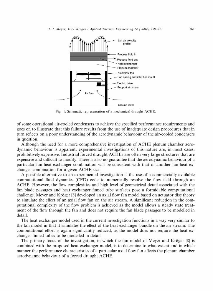
Fig. 1. Schematic representation of a mechanical draught ACHE.
C.J. Meyer, D.G. Kr€ooger / Applied Thermal Engineering 24 (2004) 359–371 361
of some operational air-cooled condensers to achieve the specified performance requirements andgoes on to illustrate that this failure results from the use of inadequate design procedures that inturn reflects on a poor understanding of the aerodynamic behaviour of the air-cooled condensersin question.
Although the need for a more comprehensive investigation of ACHE plenum chamber aero-dynamic behaviour is apparent, experimental investigations of this nature are, in most cases,prohibitively expensive. Industrial forced draught ACHEs are often very large structures that areexpensive and difficult to modify. There is also no guarantee that the aerodynamic behaviour of aparticular fan-heat exchanger combination will be consistent with that of another fan-heat ex-changer combination for a given ACHE size.
A possible alternative to an experimental investigation is the use of a commercially availablecomputational fluid dynamics (CFD) code to numerically resolve the flow field through anACHE. However, the flow complexities and high level of geometrical detail associated with thefan blade passages and heat exchanger finned tube surfaces pose a formidable computationalchallenge. Meyer and Kr€ooger [8] developed an axial flow fan model based on actuator disc theoryto simulate the effect of an axial flow fan on the air stream. A significant reduction in the com-putational complexity of the flow problem is achieved as the model allows a steady state treat-ment of the flow through the fan and does not require the fan blade passages to be modelled indetail.
The heat exchanger model used in the current investigation functions in a way very similar tothe fan model in that it simulates the effect of the heat exchanger bundle on the air stream. Thecomputational effort is again significantly reduced, as the model does not require the heat ex-changer finned tubes to be modelled in detail.
The primary focus of the investigation, in which the fan model of Meyer and Kr€ooger [8] iscombined with the proposed heat exchanger model, is to determine to what extent and in whichmanner the performance characteristics of a particular axial flow fan affects the plenum chamberaerodynamic behaviour of a forced draught ACHE.
362 C.J. Meyer, D.G. Kr€ooger / Applied Thermal Engineering 24 (2004) 359–371
2. Computational models
The commercially available CFD code used during the course of the investigation, Floþþ,solves the Reynolds-averaged Navier–Stokes equations for an incompressible fluid [9]. The effectof turbulence on the flow field is included through the application of the k–e turbulence model ofLaunder and Spalding [10].
The axial flow fan model of Meyer and Kr€ooger [8] calculates the force exerted by a fan blade onthe air at a specific location within the volume swept by the fan blades. The force calculation takesthe flow field at the leading and trailing edge of the fan blade as well as the cross-sectional profileand orientation of the fan blade at that particular location into account. The calculated force is inturn specified as a source of momentum in the Navier–Stokes equations solved by Floþþ.
Floþþ makes provision for the use of porous regions within the calculated flow field. Theporosity of a predefined porous region can be specified through user coding conveniently allowingthe heat exchanger to be modelled as a rectangular porous region within the flow field. Apart fromaffecting a reduction in the pressure of the air moving through the heat exchanger finned tubes, themost notable aerodynamic effect of the heat exchanger bundle is to direct the air stream in adirection perpendicular to the heat exchanger inlet/outlet plane. These effects can readily be in-cluded in the heat exchanger model by specifying an infinitely high porosity in the directionsparallel to the heat exchanger inlet/outlet planes and a porosity value consistent with the modelledheat exchanger pressure drop characteristics in the direction normal to the heat exchanger inlet/outlet plane.
3. Analysis
According to Meyer and Kr€ooger [7] the operating point of a proposed ACHE can be deter-mined by the solution of a 1-dimensional draught equation that equates the mechanical energy perunit volume supplied by the axial flow fan to that dissipated as the air flows through the ACHE.
Pressure changes across devices encountered by the air as it moves through the ACHE is ex-pressed in terms of dimensionless pressure loss/gain coefficients, K, so that
K ¼ Dp= qv2=2� �
ð1Þ
where Dp is the pressure drop/rise, q the air density and v an average velocity based on a char-acteristic cross-sectional area.
Fig. 2 is a schematic representation of a typical system under investigation for which thedraught equation is
DpsF þ Krecð � KTDÞqv2FC=2 ¼ KHEð þ aeHEÞqv2HE=2 ð2Þ
where DpsF is the fan static pressure rise as defined in BS 848 [11] for type A tests, Krec the di-mensionless plenum chamber recovery coefficient introduced by Meyer and Kr€ooger [7], KTD thedimensionless pressure loss coefficient of the throttling device used to regulate the volume flowrate through the ACHE, KHE the dimensionless heat exchanger pressure loss coefficient and aeHE
the kinetic energy correction factor associated with the velocity profile at the heat exchanger exit.
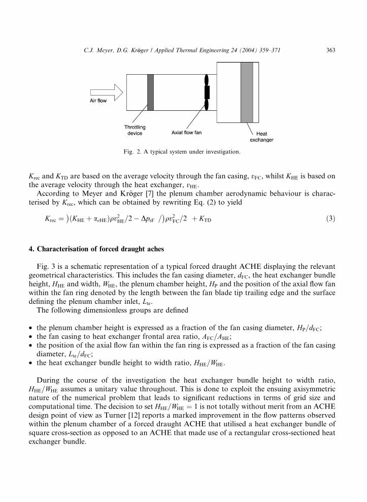
Fig. 2. A typical system under investigation.
C.J. Meyer, D.G. Kr€ooger / Applied Thermal Engineering 24 (2004) 359–371 363
Krec and KTD are based on the average velocity through the fan casing, vFC, whilst KHE is based onthe average velocity through the heat exchanger, vHE.
According to Meyer and Kr€ooger [7] the plenum chamber aerodynamic behaviour is charac-terised by Krec, which can be obtained by rewriting Eq. (2) to yield
Krec ¼ KHEð�
þ aeHEÞqv2HE=2� DpsF�= qv2FC=2� �
þ KTD ð3Þ
4. Characterisation of forced draught aches
Fig. 3 is a schematic representation of a typical forced draught ACHE displaying the relevantgeometrical characteristics. This includes the fan casing diameter, dFC, the heat exchanger bundleheight, HHE and width, WHE, the plenum chamber height, HP and the position of the axial flow fanwithin the fan ring denoted by the length between the fan blade tip trailing edge and the surfacedefining the plenum chamber inlet, Lte.
The following dimensionless groups are defined
• the plenum chamber height is expressed as a fraction of the fan casing diameter, HP=dFC;• the fan casing to heat exchanger frontal area ratio, AFC=AHE;• the position of the axial flow fan within the fan ring is expressed as a fraction of the fan casing
diameter, Lte=dFC;• the heat exchanger bundle height to width ratio, HHE=WHE.
During the course of the investigation the heat exchanger bundle height to width ratio,HHE=WHE assumes a unitary value throughout. This is done to exploit the ensuing axisymmetricnature of the numerical problem that leads to significant reductions in terms of grid size andcomputational time. The decision to set HHE=WHE ¼ 1 is not totally without merit from an ACHEdesign point of view as Turner [12] reports a marked improvement in the flow patterns observedwithin the plenum chamber of a forced draught ACHE that utilised a heat exchanger bundle ofsquare cross-section as opposed to an ACHE that made use of a rectangular cross-sectioned heatexchanger bundle.
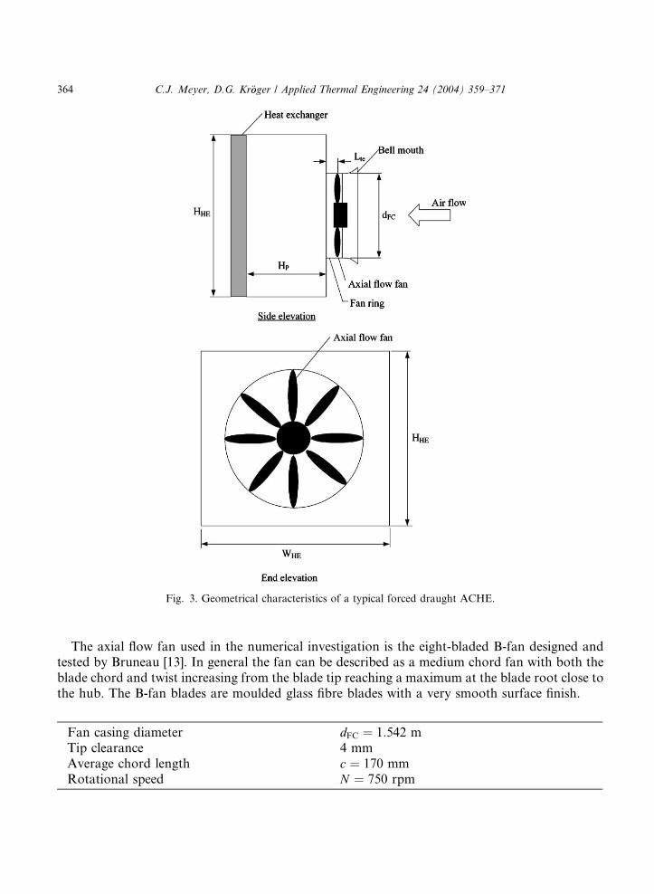
Fig. 3. Geometrical characteristics of a typical forced draught ACHE.
364 C.J. Meyer, D.G. Kr€ooger / Applied Thermal Engineering 24 (2004) 359–371
The axial flow fan used in the numerical investigation is the eight-bladed B-fan designed andtested by Bruneau [13]. In general the fan can be described as a medium chord fan with both theblade chord and twist increasing from the blade tip reaching a maximum at the blade root close tothe hub. The B-fan blades are moulded glass fibre blades with a very smooth surface finish.
Fan casing diameter dFC ¼ 1:542 mTip clearance 4 mmAverage chord length c ¼ 170 mmRotational speed N ¼ 750 rpm
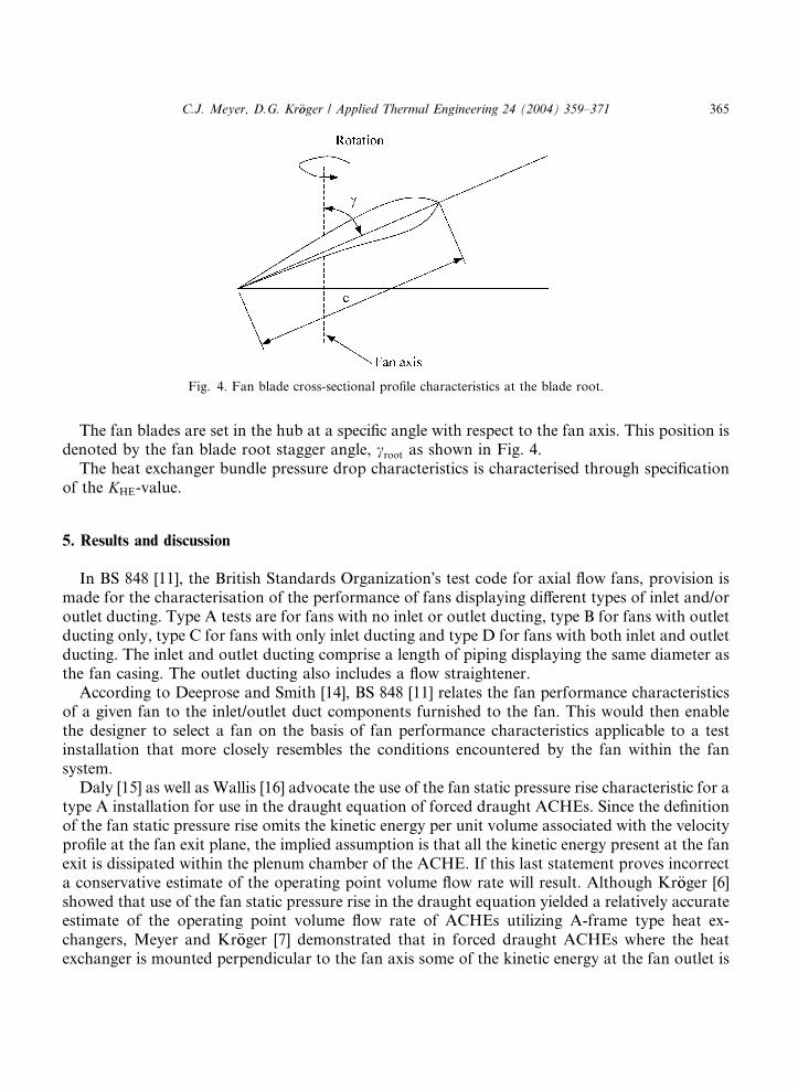
Fig. 4. Fan blade cross-sectional profile characteristics at the blade root.
C.J. Meyer, D.G. Kr€ooger / Applied Thermal Engineering 24 (2004) 359–371 365
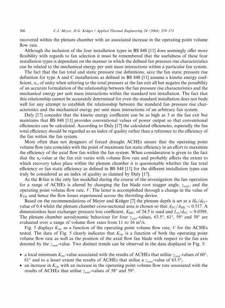
The fan blades are set in the hub at a specific angle with respect to the fan axis. This position isdenoted by the fan blade root stagger angle, croot as shown in Fig. 4.
The heat exchanger bundle pressure drop characteristics is characterised through specificationof the KHE-value.
5. Results and discussion
In BS 848 [11], the British Standards Organization�s test code for axial flow fans, provision ismade for the characterisation of the performance of fans displaying different types of inlet and/oroutlet ducting. Type A tests are for fans with no inlet or outlet ducting, type B for fans with outletducting only, type C for fans with only inlet ducting and type D for fans with both inlet and outletducting. The inlet and outlet ducting comprise a length of piping displaying the same diameter asthe fan casing. The outlet ducting also includes a flow straightener.
According to Deeprose and Smith [14], BS 848 [11] relates the fan performance characteristicsof a given fan to the inlet/outlet duct components furnished to the fan. This would then enablethe designer to select a fan on the basis of fan performance characteristics applicable to a testinstallation that more closely resembles the conditions encountered by the fan within the fansystem.
Daly [15] as well as Wallis [16] advocate the use of the fan static pressure rise characteristic for atype A installation for use in the draught equation of forced draught ACHEs. Since the definitionof the fan static pressure rise omits the kinetic energy per unit volume associated with the velocityprofile at the fan exit plane, the implied assumption is that all the kinetic energy present at the fanexit is dissipated within the plenum chamber of the ACHE. If this last statement proves incorrecta conservative estimate of the operating point volume flow rate will result. Although Kr€ooger [6]showed that use of the fan static pressure rise in the draught equation yielded a relatively accurateestimate of the operating point volume flow rate of ACHEs utilizing A-frame type heat ex-changers, Meyer and Kr€ooger [7] demonstrated that in forced draught ACHEs where the heatexchanger is mounted perpendicular to the fan axis some of the kinetic energy at the fan outlet is
366 C.J. Meyer, D.G. Kr€ooger / Applied Thermal Engineering 24 (2004) 359–371
recovered within the plenum chamber with an associated increase in the operating point volumeflow rate.
Although the inclusion of the four installation types in BS 848 [11] does seemingly offer moreflexibility with regards to fan selection it must be remembered that the usefulness of these fourinstallation types is dependant on the manner in which the defined fan pressure rise characteristicscan be related to the mechanical energy per unit mass interactions within a particular fan system.
The fact that the fan total and static pressure rise definitions, save the fan static pressure risedefinition for type A and C installations as defined in BS 848 [11] assume a kinetic energy coef-ficient, ae, of unity when referring to the total pressure at the fan exit all but negates the possibilityof an accurate formulation of the relationship between the fan pressure rise characteristics and themechanical energy per unit mass interactions within the standard test installation. The fact thatthis relationship cannot be accurately determined for even the standard installation does not bodewell for any attempt to establish the relationship between the standard fan pressure rise char-acteristics and the mechanical energy per unit mass interactions of an arbitrary fan system.
Daly [17] concedes that the kinetic energy coefficient can be as high as 3 at the fan exit butmaintains that BS 848 [11] provides conventional values of power output so that conventionalefficiencies can be calculated. According to Daly [17] the calculated efficiencies, especially the fantotal efficiency should be regarded as an index of quality rather than a reference to the efficiency ofthe fan within the fan system.
More often than not designers of forced draught ACHEs ensure that the operating pointvolume flow rate coincides with the point of maximum fan static efficiency in an effort to maximizethe efficiency of the axial flow fan within the fan system. When consideration is given to the factthat the ae-value at the fan exit varies with volume flow rate and probably affects the extent towhich recovery takes place within the plenum chamber it is questionable whether the fan totalefficiency or fan static efficiency as defined in BS 848 [11] for the different installation types cantruly be considered as an index of quality as claimed by Daly [17].
As the B-fan is the only fan modelled during the course of the investigation the fan operationfor a range of ACHEs is altered by changing the fan blade root stagger angle, croot, and theoperating point volume flow rate, V . The latter is accomplished through a change in the value ofKTD and hence the flow losses experienced across the throttling device.
Based on the recommendations of Meyer and Kr€ooger [7] the plenum depth is set at a HP=dFC-value of 0.4 whilst the plenum chamber cross-sectional area is chosen so that AFC=AHE ¼ 0:517. Adimensionless heat exchanger pressure loss coefficient, KHE, of 24.5 is used and Lte=dFC ¼ 0:0389.The plenum chamber aerodynamic behaviour for four croot-values, 63.5�, 61�, 59� and 58� areevaluated over a range of volume flow rates from 11 to 16 m3/s.
Fig. 5 displays Krec as a function of the operating point volume flow rate, V for the ACHEstested. The data of Fig. 5 clearly indicates that Krec is a function of both the operating pointvolume flow rate as well as the position of the axial flow fan blade with respect to the fan axisdenoted by the croot-value. Two distinct trends can be observed in the data displayed in Fig. 5:
• a local minimum Krec-value associated with the results of ACHEs that utilise croot-values of 60�,61� and to a lesser extent the results of ACHEs that utilise a croot-value of 63.5�;
• an increase in Krec with an increase in the operating point volume flow rate associated with theresults of ACHEs that utilise croot-values of 58� and 59�.
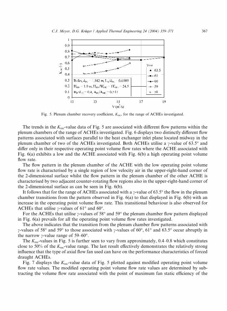
Fig. 5. Plenum chamber recovery coefficient, Krec, for the range of ACHEs investigated.
C.J. Meyer, D.G. Kr€ooger / Applied Thermal Engineering 24 (2004) 359–371 367
The trends in the Krec-value data of Fig. 5 are associated with different flow patterns within theplenum chambers of the range of ACHEs investigated. Fig. 6 displays two distinctly different flowpatterns associated with surfaces parallel to the heat exchanger inlet plane located midway in theplenum chamber of two of the ACHEs investigated. Both ACHEs utilise a c-value of 63.5� anddiffer only in their respective operating point volume flow rates where the ACHE associated withFig. 6(a) exhibits a low and the ACHE associated with Fig. 6(b) a high operating point volumeflow rate.
The flow pattern in the plenum chamber of the ACHE with the low operating point volumeflow rate is characterised by a single region of low velocity air in the upper-right-hand corner ofthe 2-dimensional surface whilst the flow pattern in the plenum chamber of the other ACHE ischaracterised by two adjacent counter-rotating flow regions also in the upper-right-hand corner ofthe 2-dimensional surface as can be seen in Fig. 6(b).
It follows that for the range of ACHEs associated with a c-value of 63.5� the flow in the plenumchamber transitions from the pattern observed in Fig. 6(a) to that displayed in Fig. 6(b) with anincrease in the operating point volume flow rate. This transitional behaviour is also observed forACHEs that utilise c-values of 61� and 60�.
For the ACHEs that utilise c-values of 58� and 59� the plenum chamber flow pattern displayedin Fig. 6(a) prevails for all the operating point volume flow rates investigated.
The above indicates that the transition from the plenum chamber flow patterns associated withc-values of 58� and 59� to those associated with c-values of 60�, 61� and 63.5� occur abruptly inthe narrow c-value range of 59–60�.
The Krec-values in Fig. 5 is further seen to vary from approximately, 0.4–0.8 which constitutesclose to 50% of the Krec-value range. The last result effectively demonstrates the relatively stronginfluence that the type of axial flow fan used can have on the performance characteristics of forceddraught ACHEs.
Fig. 7 displays the Krec-value data of Fig. 5 plotted against modified operating point volumeflow rate values. The modified operating point volume flow rate values are determined by sub-tracting the volume flow rate associated with the point of maximum fan static efficiency of the
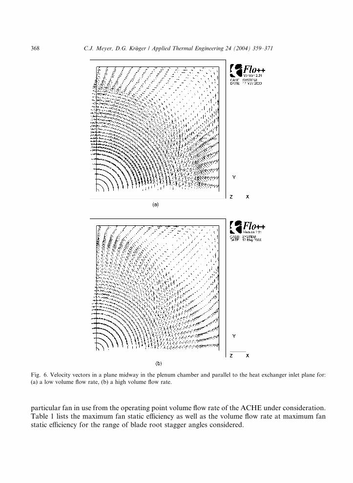
Fig. 6. Velocity vectors in a plane midway in the plenum chamber and parallel to the heat exchanger inlet plane for:
(a) a low volume flow rate, (b) a high volume flow rate.
368 C.J. Meyer, D.G. Kr€ooger / Applied Thermal Engineering 24 (2004) 359–371
particular fan in use from the operating point volume flow rate of the ACHE under consideration.Table 1 lists the maximum fan static efficiency as well as the volume flow rate at maximum fanstatic efficiency for the range of blade root stagger angles considered.
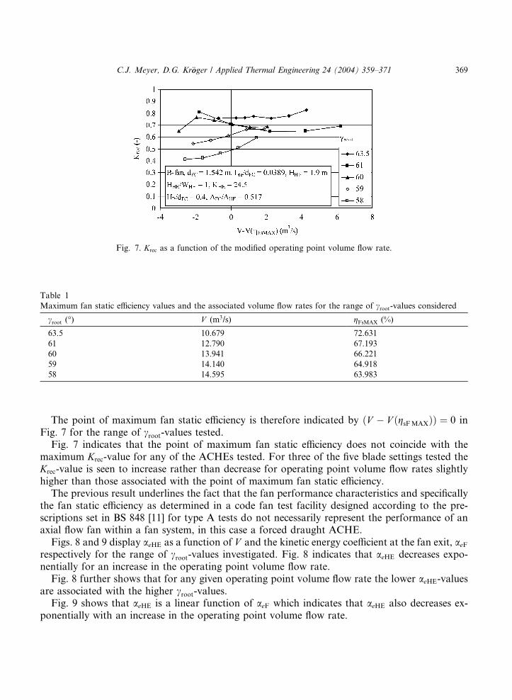
Fig. 7. Krec as a function of the modified operating point volume flow rate.
Table 1
Maximum fan static efficiency values and the associated volume flow rates for the range of croot-values considered
croot (�) V (m3/s) gFsMAX (%)
63.5 10.679 72.631
61 12.790 67.193
60 13.941 66.221
59 14.140 64.918
58 14.595 63.983
C.J. Meyer, D.G. Kr€ooger / Applied Thermal Engineering 24 (2004) 359–371 369
The point of maximum fan static efficiency is therefore indicated by ðV � V ðgsFMAXÞÞ ¼ 0 inFig. 7 for the range of croot-values tested.
Fig. 7 indicates that the point of maximum fan static efficiency does not coincide with themaximum Krec-value for any of the ACHEs tested. For three of the five blade settings tested theKrec-value is seen to increase rather than decrease for operating point volume flow rates slightlyhigher than those associated with the point of maximum fan static efficiency.
The previous result underlines the fact that the fan performance characteristics and specificallythe fan static efficiency as determined in a code fan test facility designed according to the pre-scriptions set in BS 848 [11] for type A tests do not necessarily represent the performance of anaxial flow fan within a fan system, in this case a forced draught ACHE.
Figs. 8 and 9 display aeHE as a function of V and the kinetic energy coefficient at the fan exit, aeFrespectively for the range of croot-values investigated. Fig. 8 indicates that aeHE decreases expo-nentially for an increase in the operating point volume flow rate.
Fig. 8 further shows that for any given operating point volume flow rate the lower aeHE-valuesare associated with the higher croot-values.
Fig. 9 shows that aeHE is a linear function of aeF which indicates that aeHE also decreases ex-ponentially with an increase in the operating point volume flow rate.
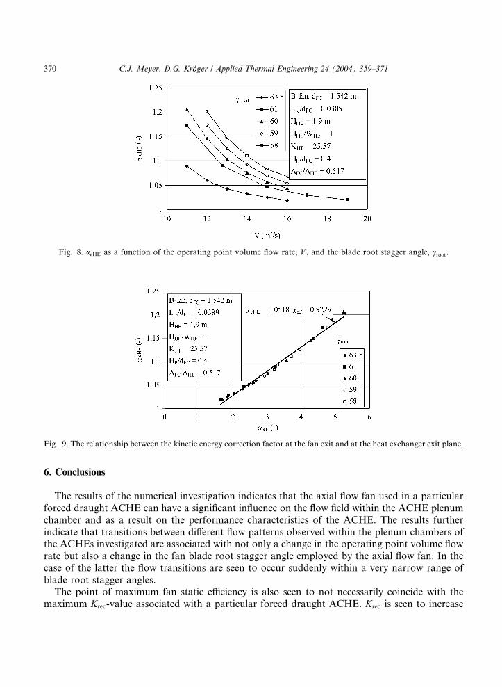
Fig. 8. aeHE as a function of the operating point volume flow rate, V , and the blade root stagger angle, croot.
Fig. 9. The relationship between the kinetic energy correction factor at the fan exit and at the heat exchanger exit plane.
370 C.J. Meyer, D.G. Kr€ooger / Applied Thermal Engineering 24 (2004) 359–371
6. Conclusions
The results of the numerical investigation indicates that the axial flow fan used in a particularforced draught ACHE can have a significant influence on the flow field within the ACHE plenumchamber and as a result on the performance characteristics of the ACHE. The results furtherindicate that transitions between different flow patterns observed within the plenum chambers ofthe ACHEs investigated are associated with not only a change in the operating point volume flowrate but also a change in the fan blade root stagger angle employed by the axial flow fan. In thecase of the latter the flow transitions are seen to occur suddenly within a very narrow range ofblade root stagger angles.
The point of maximum fan static efficiency is also seen to not necessarily coincide with themaximum Krec-value associated with a particular forced draught ACHE. Krec is seen to increase
C.J. Meyer, D.G. Kr€ooger / Applied Thermal Engineering 24 (2004) 359–371 371
with an increase in operating point volume flow rates in excess of the volume flow rate associatedwith the point of maximum fan static efficiency for the ACHEs investigated.
The kinetic energy coefficient at the heat exchanger bundle outlet, aeHE is a linear function ofthe kinetic energy coefficient at the fan outlet, aeF. aeHE is seen to decrease exponentially with anincrease in the operating point volume flow rate. At a constant operating point volume flow rateaeHE is seen to increase with a decrease in the croot-value for the range of ACHEs investigated.
It is concluded that the influence of the axial flow fan on ACHE performance characteristics arenot only relatively strong but also very difficult to predict. This state of affairs is most probably aresult of the sensitivity of forced draught ACHE performance characteristics to the characteristicsof the velocity field at the fan exit, which, in turn is a function of the type of axial flow fan used.The large degree of variation associated with the different axial flow fans used in industry com-plicates further investigation of the influence of axial flow fans on ACHE performance charac-teristics.
References
[1] H.-H. Von Cleve, Die Luftgek€uuhlte Kondensationsanlange des 4000 MW-Kraftswerks Matimba/S€uudafrika, VGB
Kraftwerkstecchnik 64 (4) (1984).
[2] H. Knirsch, Design and construction of direct dry cooling units, in: Proc. VGB Conference, South Africa, vol. 1,
1987, pp. 54–69.
[3] H. Knirsch, Design and construction of large direct cooled units for thermal power plants, in: ASME Joint Power
Conference, Paper 90-JPGC/Pwr-26, Boston, 1990.
[4] H. Knirsch, Dry cooling towers at biggest coal fuel power station, Modern Power System, Ruislip, England, July
1991.
[5] H.B. Goldschagg, Lessons learned from the world�s largest forced draft direct air-cooled condenser, in: EPRI
Meeting, Washington, 1993.
[6] D.G. Kr€ooger, Fan performance in air-cooled steam condensers, Heat Recovery Systems & CHP 14 (4) (1994) 391–
399.
[7] C.J. Meyer, D.G. Kr€ooger, Plenum chamber flow losses in forced draught air-cooled heat exchangers, Applied
Thermal Engineering 18 (9–10) (1998) 875–893.
[8] C.J. Meyer, D.G. Kr€ooger, Numerical simulation of the flow field in the vicinity of an axial flow fan, International
Journal for Numerical Methods in Fluids 36 (2001) 947–969.
[9] H.K. Versteeg, W. Malalasekera, An Introduction to Computational Fluid Dynamics, Prentice Hall, Harlow, 1995.
[10] B.E. Launder, D.B. Spalding, The numerical computation of turbulent flows, Computer Methods in Applied
Mechanics and Engineering 3 (1974) 269–289.
[11] British Standards Institution, Fans for general purposes, Part 1, Methods of testing performance, BS 848, 1980.
[12] J.T. Turner, The aerodynamics of forced draught air-cooled heat exchangers, in: International Symposium on
Cooling Systems, BHRA Fluid Engineering, Cranfield, England, February 1975.
[13] P.R.P. Bruneau, The Design of a Single Rotor Axial Flow Fan for a Cooling Tower Application, M. Eng. (Mech.)
Thesis, Department of Mechanical Engineering, University of Stellenbosch, South Africa, 1994.
[14] W.M. Deeprose, T.W. Smith, The usefulness of BS 848 Part 1: 1980 in establishing the installed performance of a
fan, The Institution of Mechanical Engineers Conference Publications 1984-4, C115/84, London, May 1984.
[15] B.B. Daly, Woods Practical Guide to Fan Engineering, Woods of Colchester Limited, Colchester, 1978.
[16] R.A. Wallis, Axial Flow Fans and Ducts, John Wiley & Sons, New York, 1983.
[17] B.B. Daly, Interaction between the fan and the system, The Institution of Mechanical Engineers Conference
Publications 1984-4, C110/84, London, May 1984.