microscope system
TRANSCRIPT
Microscope SystemFinal Design Review Report
Ginnie Brannaman [email protected]
Ricardo Lasa [email protected]
Gavin Shavey [email protected]
Sponsor: Dr. Trevor Cardinal
2
Table of Contents1. Executive Summary 3 2. Introduction and Background 4
1. Introduction 4 2. Background 5
3. Customer Requirements and Design Specifications 7 1. IFU 7 2. Product Design Specifications 7 3. House of Quality 8
4. Stage Gate Process 9 1. Concept Review 9 2. Design Freeze 11 3. Design Review 11
5. Description of Final Prototype Design 13 1. Overview 13 2. Design Justification 13 3. Analysis 13 4. Cost Breakdown 14 5. Safety Considerations 14
6. Prototype Development 15 1. Model Analyses 15 2. Evolution of Prototypes 20 3. Manufacturing Process 20 4. Divergence Between Final Design and Final Functional Prototype 21
7. IQ/OQ/PQ 22 1. DOE 22 2. Verification and Validation 23
8. Conclusions and Recommendations 24 1. Recommendations 24 2. Conclusions 24
9. Acknowledgments 25 10. Appendices 26
1. Appendix A: References 26 2. Appendix B: Project Plan (PERT Chart) 28 3. Appendix C: CAD Drawings 29 4. Appendix D: FMEA, Hazard & Risk Assessment 32 5. Appendix E: Pugh Chart 34 6. Appendix F: Vendor Information, Specifications, and Data Sheets 35 7. Appendix G: Budget 36 8. Appendix H: DHF 37
3
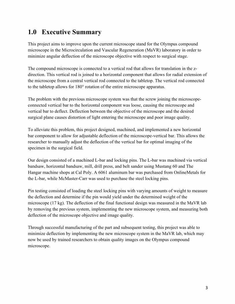
1.0 Executive SummaryThis project aims to improve upon the current microscope stand for the Olympus compound microscope in the Microcirculation and Vascular Regeneration (MaVR) laboratory in order to minimize angular deflection of the microscope objective with respect to surgical stage.The compound microscope is connected to a vertical rod that allows for translation in the z-direction. This vertical rod is joined to a horizontal component that allows for radial extension of the microscope from a central vertical rod connected to the tabletop. The vertical rod connected to the tabletop allows for 180° rotation of the entire microscope apparatus. The problem with the previous microscope system was that the screw joining the microscope-connected vertical bar to the horizontal component was loose, causing the microscope and vertical bar to deflect. Deflection between the objective of the microscope and the desired surgical plane causes distortion of light entering the microscope and poor image quality. To alleviate this problem, this project designed, machined, and implemented a new horizontal bar component to allow for adjustable deflection of the microscope-vertical bar. This allows the researcher to manually adjust the deflection of the vertical bar for optimal imaging of the specimen in the surgical field.Our design consisted of a machined L-bar and locking pins. The L-bar was machined via vertical bandsaw, horizontal bandsaw, mill, drill press, and belt sander using Mustang 60 and The Hangar machine shops at Cal Poly. A 6061 aluminum bar was purchased from OnlineMetals for the L-bar, while McMaster-Carr was used to purchase the steel locking pins.Pin testing consisted of loading the steel locking pins with varying amounts of weight to measure the deflection and determine if the pin would yield under the determined weight of the microscope (17 kg). The deflection of the final functional design was measured in the MaVR lab by removing the previous system, implementing the new microscope system, and measuring both deflection of the microscope objective and image quality.Through successful manufacturing of the part and subsequent testing, this project was able to minimize deflection by implementing the new microscope system in the MaVR lab, which may now be used by trained researchers to obtain quality images on the Olympus compound microscope.

4
2.0 Introduction and Background
2.1 IntroductionThis project intends to produce a stabilization and translation system for the compound microscope found in Dr. Trevor Cardinal’s research lab. This microscope’s objective is currently not completely perpendicular to the specimen stage, which leads to poor image quality. For this project, we will be trying to correct this deflection. The stakeholders in this project with be Dr. Cardinal and his research team because they will be directly benefiting from the enhanced ability of the compound microscope to acquire high quality images. In Dr. Trevor Cardinal’s research lab, he and his team perform surgeries on mice under anesthesia in an effort to study vascular regeneration. They are currently trying to induce a natural bypass in the mice by ligating an artery of interest and studying its effects on the vasculature of the muscle of interest over time. Currently, the microscope system consists of a stage that can be moved in the x and y direction, a heat mat for the mice, two stereoscopes used for the dissection of the mice specimens, and a compound microscope that is used for the imaging. During surgery, the stereoscope is used in order to obtain a magnified, 3D image of the surgical site. Once the region of interest is exposed, the stereoscope is rotated away from the sample and the compound microscope is rotated over the sample and used to analyze the vasculature at a much greater magnification. The stereo and compound microscopes are supported by individual stands and bases that are bolted to the table, allowing them to move in 180° and extend radially. The problem is that the weight of the microscope is causing deflection in a pivot joint connecting the bars for radial extension and z-direction translation. This is a major issue because it causes the objective to not be completely perpendicular to the stage, causing poor quality images of the specimen. Our main objectives for this project will be to keep the compound microscope and accompanying stereoscopes in their current environment and set up, fix the perpendicularity issue of the compound microscope objective, potentially be able to move the stage that surgeries are performed on in the z-direction, and still be able to move the compound microscope between the two stereoscopes. The goal of this project was to produce a modification to the previous microscope system that will significantly reduce the deflection of the compound microscope to a workable range so that the researchers in the MaVR lab may obtain quality images during surgery.
5
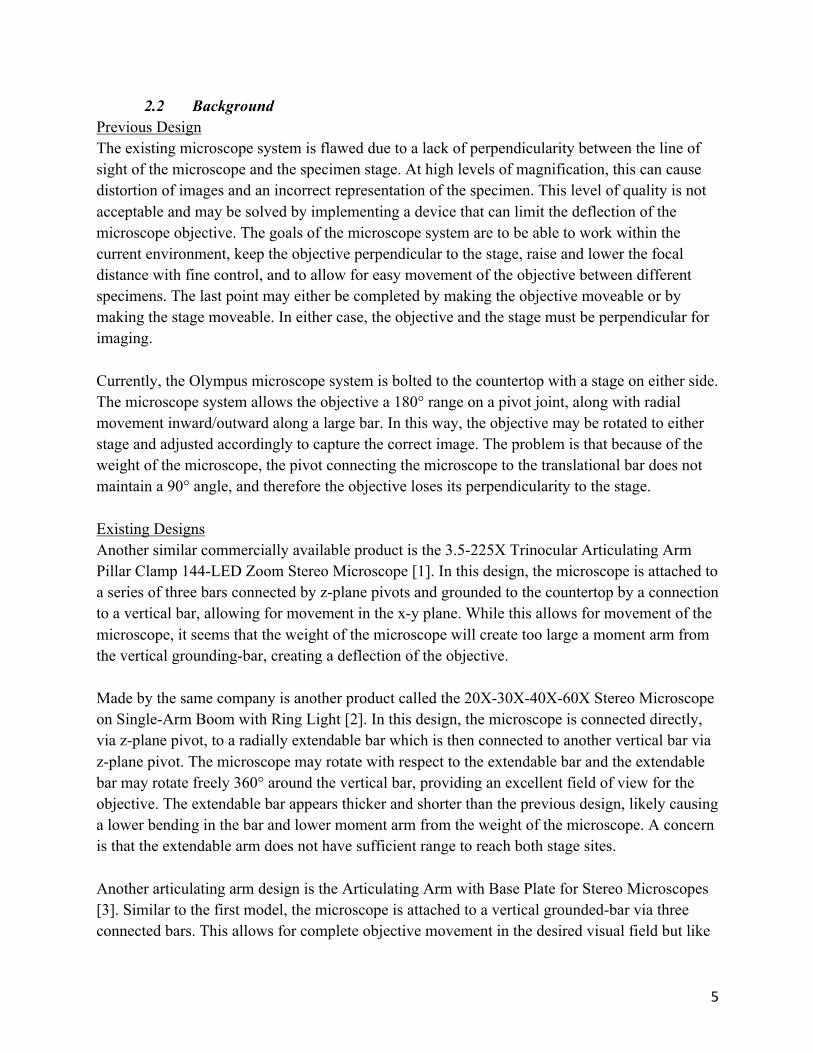
2.2 BackgroundPrevious DesignThe existing microscope system is flawed due to a lack of perpendicularity between the line of sight of the microscope and the specimen stage. At high levels of magnification, this can cause distortion of images and an incorrect representation of the specimen. This level of quality is not acceptable and may be solved by implementing a device that can limit the deflection of the microscope objective. The goals of the microscope system are to be able to work within the current environment, keep the objective perpendicular to the stage, raise and lower the focal distance with fine control, and to allow for easy movement of the objective between different specimens. The last point may either be completed by making the objective moveable or by making the stage moveable. In either case, the objective and the stage must be perpendicular for imaging. Currently, the Olympus microscope system is bolted to the countertop with a stage on either side. The microscope system allows the objective a 180° range on a pivot joint, along with radial movement inward/outward along a large bar. In this way, the objective may be rotated to either stage and adjusted accordingly to capture the correct image. The problem is that because of the weight of the microscope, the pivot connecting the microscope to the translational bar does not maintain a 90° angle, and therefore the objective loses its perpendicularity to the stage. Existing DesignsAnother similar commercially available product is the 3.5-225X Trinocular Articulating Arm Pillar Clamp 144-LED Zoom Stereo Microscope [1]. In this design, the microscope is attached to a series of three bars connected by z-plane pivots and grounded to the countertop by a connection to a vertical bar, allowing for movement in the x-y plane. While this allows for movement of the microscope, it seems that the weight of the microscope will create too large a moment arm from the vertical grounding-bar, creating a deflection of the objective.Made by the same company is another product called the 20X-30X-40X-60X Stereo Microscope on Single-Arm Boom with Ring Light [2]. In this design, the microscope is connected directly, via z-plane pivot, to a radially extendable bar which is then connected to another vertical bar via z-plane pivot. The microscope may rotate with respect to the extendable bar and the extendable bar may rotate freely 360° around the vertical bar, providing an excellent field of view for the objective. The extendable bar appears thicker and shorter than the previous design, likely causing a lower bending in the bar and lower moment arm from the weight of the microscope. A concern is that the extendable arm does not have sufficient range to reach both stage sites. Another articulating arm design is the Articulating Arm with Base Plate for Stereo Microscopes [3]. Similar to the first model, the microscope is attached to a vertical grounded-bar via three connected bars. This allows for complete objective movement in the desired visual field but like
6
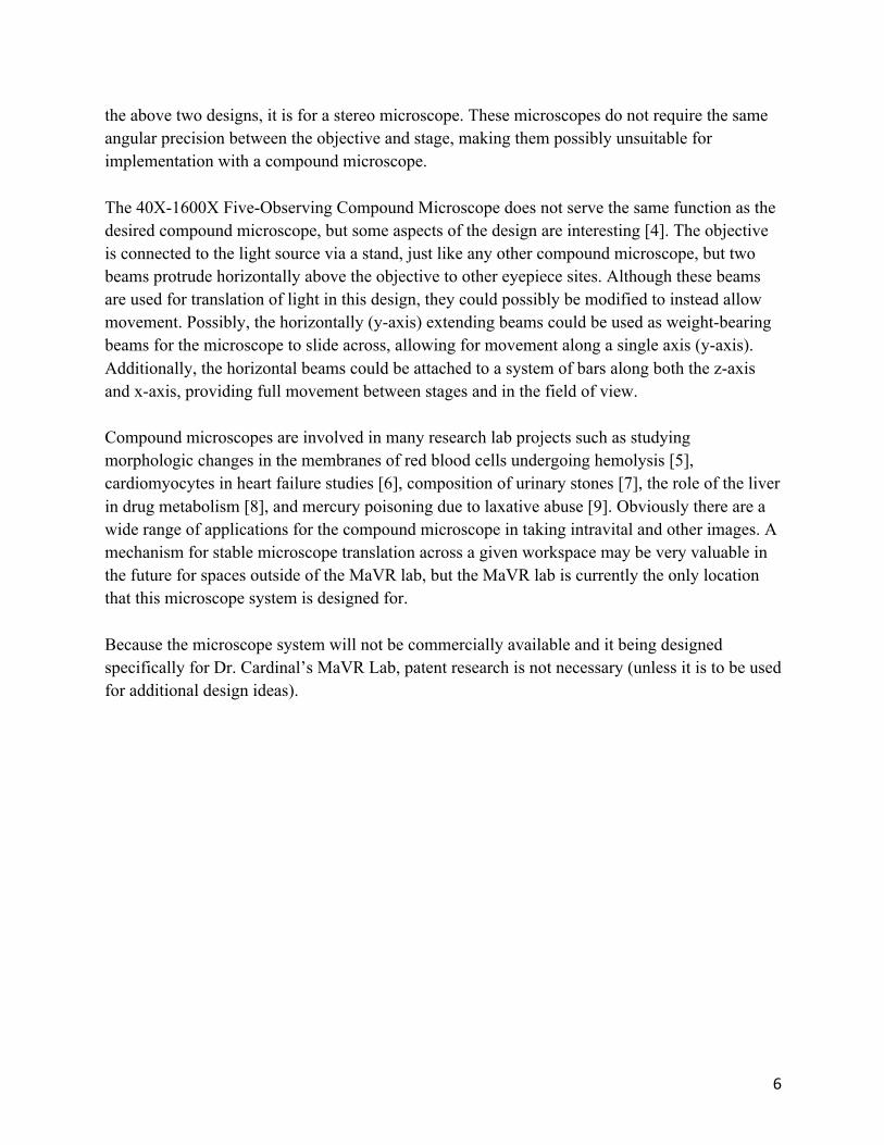
the above two designs, it is for a stereo microscope. These microscopes do not require the same angular precision between the objective and stage, making them possibly unsuitable for implementation with a compound microscope.The 40X-1600X Five-Observing Compound Microscope does not serve the same function as the desired compound microscope, but some aspects of the design are interesting [4]. The objective is connected to the light source via a stand, just like any other compound microscope, but two beams protrude horizontally above the objective to other eyepiece sites. Although these beams are used for translation of light in this design, they could possibly be modified to instead allow movement. Possibly, the horizontally (y-axis) extending beams could be used as weight-bearing beams for the microscope to slide across, allowing for movement along a single axis (y-axis). Additionally, the horizontal beams could be attached to a system of bars along both the z-axis and x-axis, providing full movement between stages and in the field of view. Compound microscopes are involved in many research lab projects such as studying morphologic changes in the membranes of red blood cells undergoing hemolysis [5], cardiomyocytes in heart failure studies [6], composition of urinary stones [7], the role of the liver in drug metabolism [8], and mercury poisoning due to laxative abuse [9]. Obviously there are a wide range of applications for the compound microscope in taking intravital and other images. A mechanism for stable microscope translation across a given workspace may be very valuable in the future for spaces outside of the MaVR lab, but the MaVR lab is currently the only location that this microscope system is designed for.Because the microscope system will not be commercially available and it being designed specifically for Dr. Cardinal’s MaVR Lab, patent research is not necessary (unless it is to be used for additional design ideas).

7
3.0 Customer Requirements and Design Specifications
3.1 Indications for UseThis part will modify the current microscope support system to reduce the current deflection issue while keeping the current functions of the stand. The microscope system will be able to rotate angularly between surgical stations, extend radially, and translate in the z-direction with minimal deflection in order to produce clear images.It is intended to be used by research institutions performing intravital microscopy on specimens. The end user will be a qualified research member trained in the use of a compound microscope by their institution and approved at the discretion of the research facility.
3.2 Product Design Specifications
Figure 1: Product Design Specification Matrix
Successful implementation of a new system relies on the system supporting the weight of the microscope, keeping the objective parallel with the surgical field, and maintaining the mobility of the compound microscope to move between surgical stages. These requirements ensure protection, improved performance, and maintained functionality of the microscope.
8
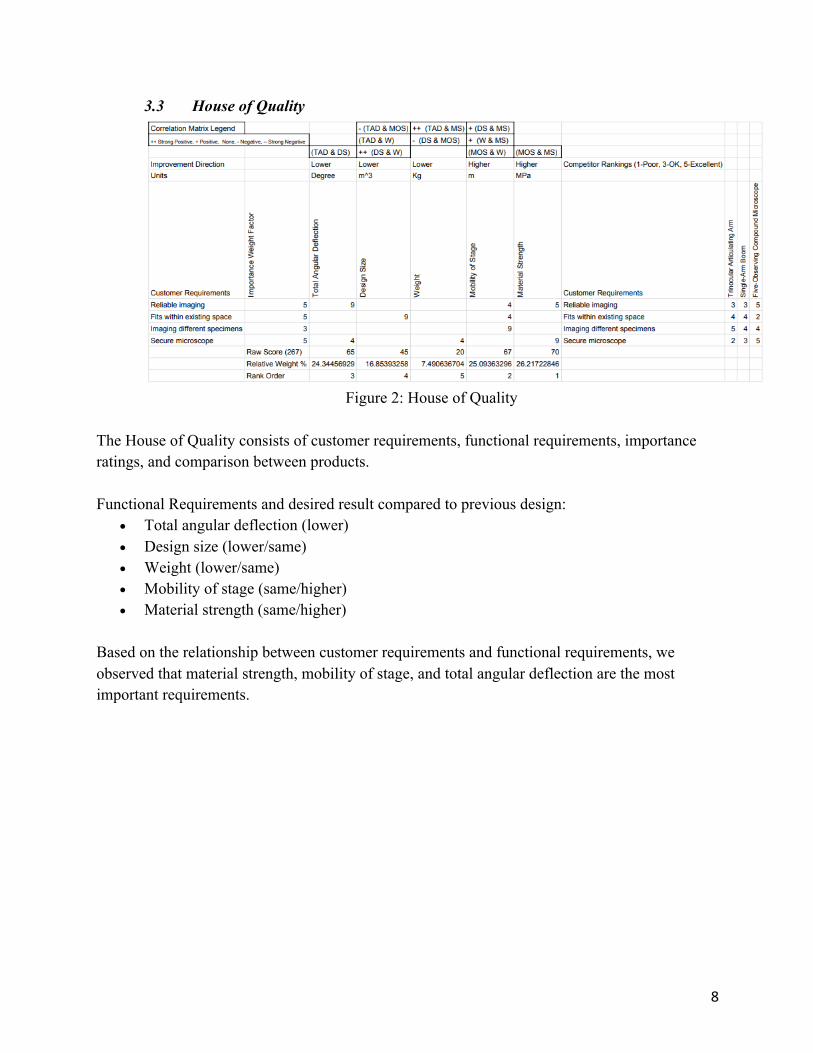
3.3 House of Quality
Figure 2: House of Quality
The House of Quality consists of customer requirements, functional requirements, importance ratings, and comparison between products.Functional Requirements and desired result compared to previous design:
• Total angular deflection (lower) • Design size (lower/same) • Weight (lower/same) • Mobility of stage (same/higher) • Material strength (same/higher)
Based on the relationship between customer requirements and functional requirements, we observed that material strength, mobility of stage, and total angular deflection are the most important requirements.
9
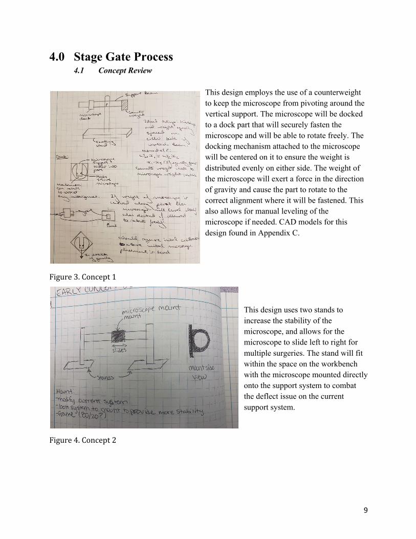
4.0 Stage Gate Process4.1 Concept Review
This design employs the use of a counterweight to keep the microscope from pivoting around the vertical support. The microscope will be docked to a dock part that will securely fasten the microscope and will be able to rotate freely. The docking mechanism attached to the microscope will be centered on it to ensure the weight is distributed evenly on either side. The weight of the microscope will exert a force in the direction of gravity and cause the part to rotate to the correct alignment where it will be fastened. This also allows for manual leveling of the microscope if needed. CAD models for this design found in Appendix C.
Figure3.Concept1 This design uses two stands to increase the stability of the microscope, and allows for the microscope to slide left to right for multiple surgeries. The stand will fit within the space on the workbench with the microscope mounted directly onto the support system to combat the deflect issue on the current support system.
Figure4.Concept2

10
This design employs the use of three sliding bars in order to allow for rigid movement in the x, y, and z plane. Two large bases will be bolted to the work surface to allow for structure stability and use of the workspace as a datum for deflection angle. Steel bars in the y-direction allow for translation along the y-axis. A strong fastening mechanism will have to be used on the y-direction bars in order to mitigate slipping due to gravity. Bars also extend in the z-direction,
allowing for z-translation. These will not have to be as long because z-translation will be limited. The compound microscope will be placed on a track system with a docking mechanism to ensure the microscope stays attached to the x-bar, with the help of gravity. The x-bar will be long enough to allow the stereoscopes to be pushed all the way to the end for compound microscope viewing of samples.
Figure5.Concept3Design SelectionThe design was selected using a PUGH chart (Appendix E). The three designs were compared to an existing product that can be considered as the gold standard for our intended application. Design 1 was selected as it improves upon all but one of the existing criteria. This concept provides better alignment capabilities, reduced size and weight, and increased mobility. These are key customer requirements which the concept design improves upon. The concept has the ability to manually adjust the angle deflection to calibrate the microscope alignment, which was unique to this design. It also has the widest range of mobility as it can rotate around the vertical beam as well as translate vertically along it. The counterweight mechanism can be replaced by an angled beam that connects the end of the support bar on the side without the microscope to the vertical bar and provide the same counter momentum force.
11
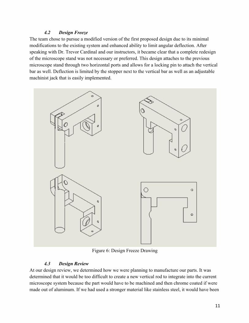
4.2 Design FreezeThe team chose to pursue a modified version of the first proposed design due to its minimal modifications to the existing system and enhanced ability to limit angular deflection. After speaking with Dr. Trevor Cardinal and our instructors, it became clear that a complete redesign of the microscope stand was not necessary or preferred. This design attaches to the previous microscope stand through two horizontal ports and allows for a locking pin to attach the vertical bar as well. Deflection is limited by the stopper next to the vertical bar as well as an adjustable machinist jack that is easily implemented.
Figure 6: Design Freeze Drawing
4.3 Design Review
At our design review, we determined how we were planning to manufacture our parts. It was determined that it would be too difficult to create a new vertical rod to integrate into the current microscope system because the part would have to be machined and then chrome coated if were made out of aluminum. If we had used a stronger material like stainless steel, it would have been

12
too difficult to machine the rod to the desired diameter, and we had no way to chrome coat the aluminum rod. By reusing the current vertical rod, we were able to reduce the cost, and it was then used to create the dimensions of the fork on the L-bar. We then determined that when we manufacturing the L-bar, we should use the mill and vertical band saw instead of the CNC mill in the machine shops on campus.
13
5.0 Description of Final Prototype Design
5.1 OverviewOur final prototype design created a new L bar that was more resistant to deflection while being integrated into the current support system of the compound microscope. The main features of our design are the fork for the current vertical member of the microscope to sit, the counterbore hole to secure the jack, and the pin to secure the vertical member of the microscope.
5.2 Design JustificationThis design was used in order to correct the deflection of the compound microscope in Dr. Trevor Cardinal’s lab. By increasing the thickness of the horizontal member and using the jack, we are able to change the deflection of the microscope to get photos with the highest clarity. Our design integrated into the current support system so that the lab would have the same set up as before.
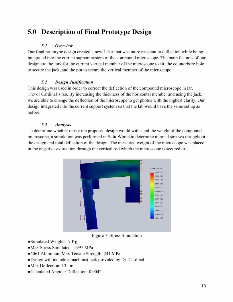
5.3 AnalysisTo determine whether or not the proposed design would withstand the weight of the compound microscope, a simulation was performed in SolidWorks to determine internal stresses throughout the design and total deflection of the design. The measured weight of the microscope was placed in the negative z-direction through the vertical rod which the microscope is secured to.
Figure 7: Stress Simulation
●Simulated Weight: 17 Kg●Max Stress Simulated: 1.997 MPa●6061 Aluminum Max Tensile Strength: 241 MPa1●Design will include a machinist jack provided by Dr. Cardinal●Max Deflection: 13 μm●Calculated Angular Deflection: 0.004°
14
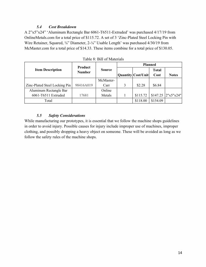
5.4 Cost BreakdownA 2”x5”x24” ‘Aluminum Rectangle Bar 6061-T6511-Extruded’ was purchased 4/17/19 from OnlineMetals.com for a total price of $115.72. A set of 3 ‘Zinc-Plated Steel Locking Pin with Wire Retainer, Squared, ⅜” Diameter, 2-⅛” Usable Length’ was purchased 4/30/19 from McMaster.com for a total price of $14.33. These items combine for a total price of $130.05.
Table 8: Bill of Materials
Item Description Product Number Source
Planned
Quantity Cost/Unit Total Cost Notes
Zinc-Plated Steel Locking Pin 98416A019 McMaster-
Carr 3 $2.28 $6.84 Aluminum Rectangle Bar
6061-T6511 Extruded 17681 Online Metals 1 $115.72 $147.25 2"x5"x24"
Total $118.00 $154.09
5.5 Safety ConsiderationsWhile manufacturing our prototypes, it is essential that we follow the machine shops guidelines in order to avoid injury. Possible causes for injury include improper use of machines, improper clothing, and possibly dropping a heavy object on someone. These will be avoided as long as we follow the safety rules of the machine shops.
15
6.0 Prototype Development
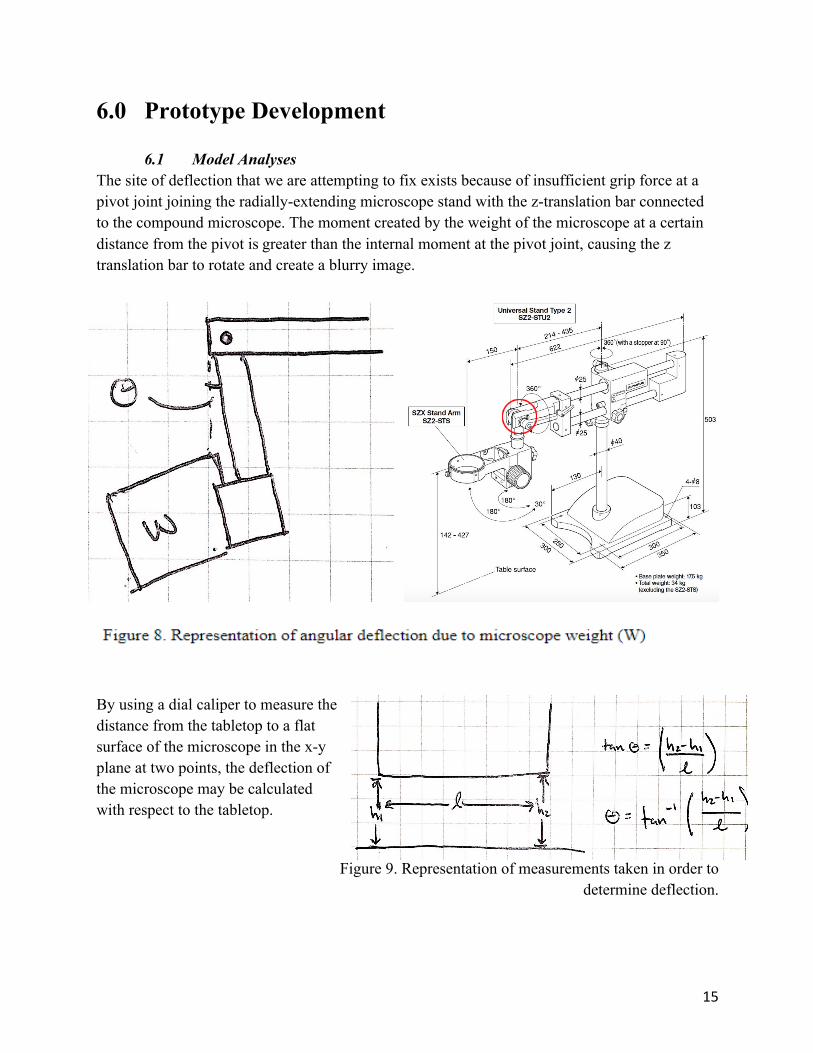
6.1 Model AnalysesThe site of deflection that we are attempting to fix exists because of insufficient grip force at a pivot joint joining the radially-extending microscope stand with the z-translation bar connected to the compound microscope. The moment created by the weight of the microscope at a certain distance from the pivot isgreater than the internal moment at the pivot joint, causing the z translation bar to rotate and create a blurry image.
By using a dial caliper to measure the distance from the tabletop to a flat surface of the microscope in the x-y plane at two points, the deflection of the microscope may be calculated with respect to the tabletop.
Figure 9. Representation of measurements taken in order to determine deflection.
16
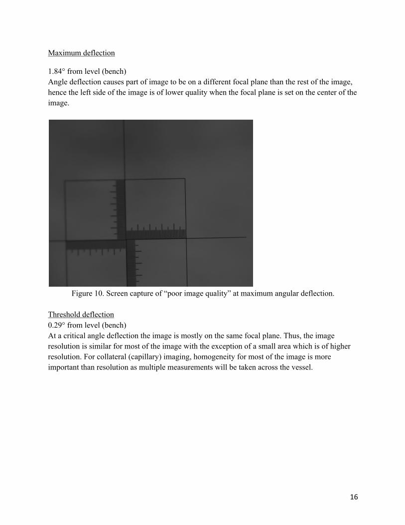
Maximum deflection
1.84° from level (bench)Angle deflection causes part of image to be on a different focal plane than the rest of the image, hence the left side of the image is of lower quality when the focal plane is set on the center of the image.
Figure 10. Screen capture of “poor image quality” at maximum angular deflection.
Threshold deflection0.29° from level (bench)At a critical angle deflection the image is mostly on the same focal plane. Thus, the image resolution is similar for most of the image with the exception of a small area which is of higher resolution. For collateral (capillary) imaging, homogeneity for most of the image is more important than resolution as multiple measurements will be taken across the vessel.
17
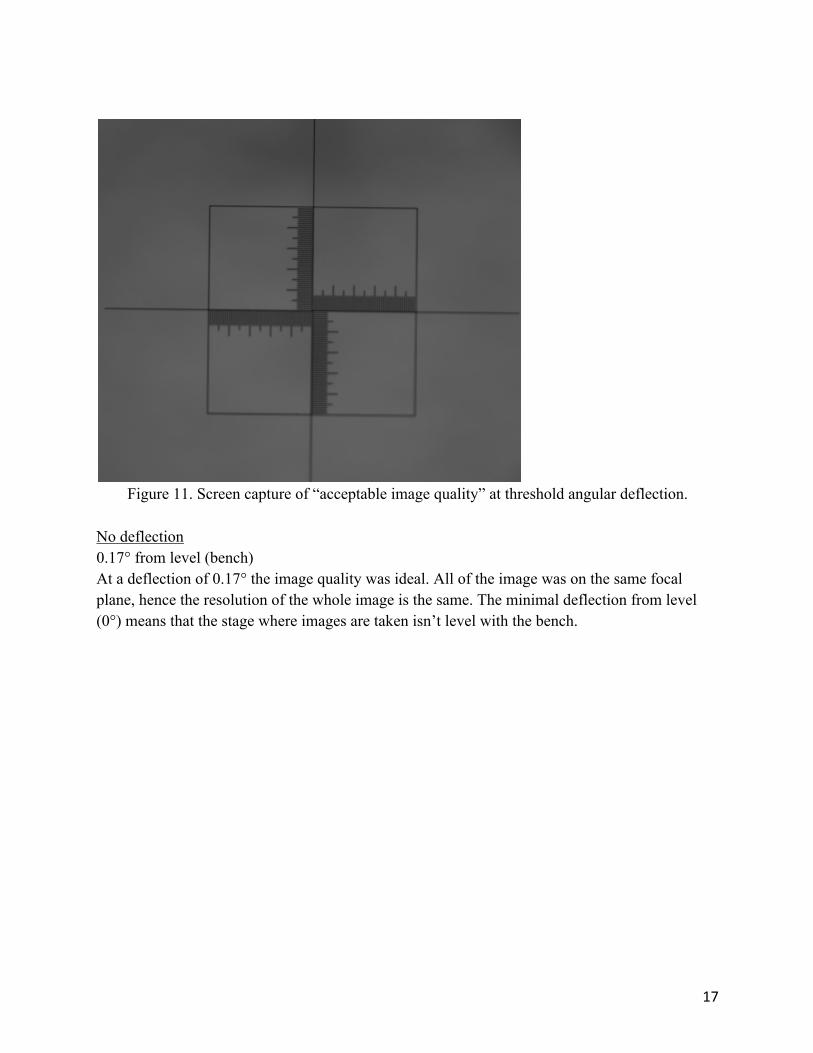
Figure 11. Screen capture of “acceptable image quality” at threshold angular deflection.
No deflection0.17° from level (bench)At a deflection of 0.17° the image quality was ideal. All of the image was on the same focal plane, hence the resolution of the whole image is the same. The minimal deflection from level (0°) means that the stage where images are taken isn’t level with the bench.
18
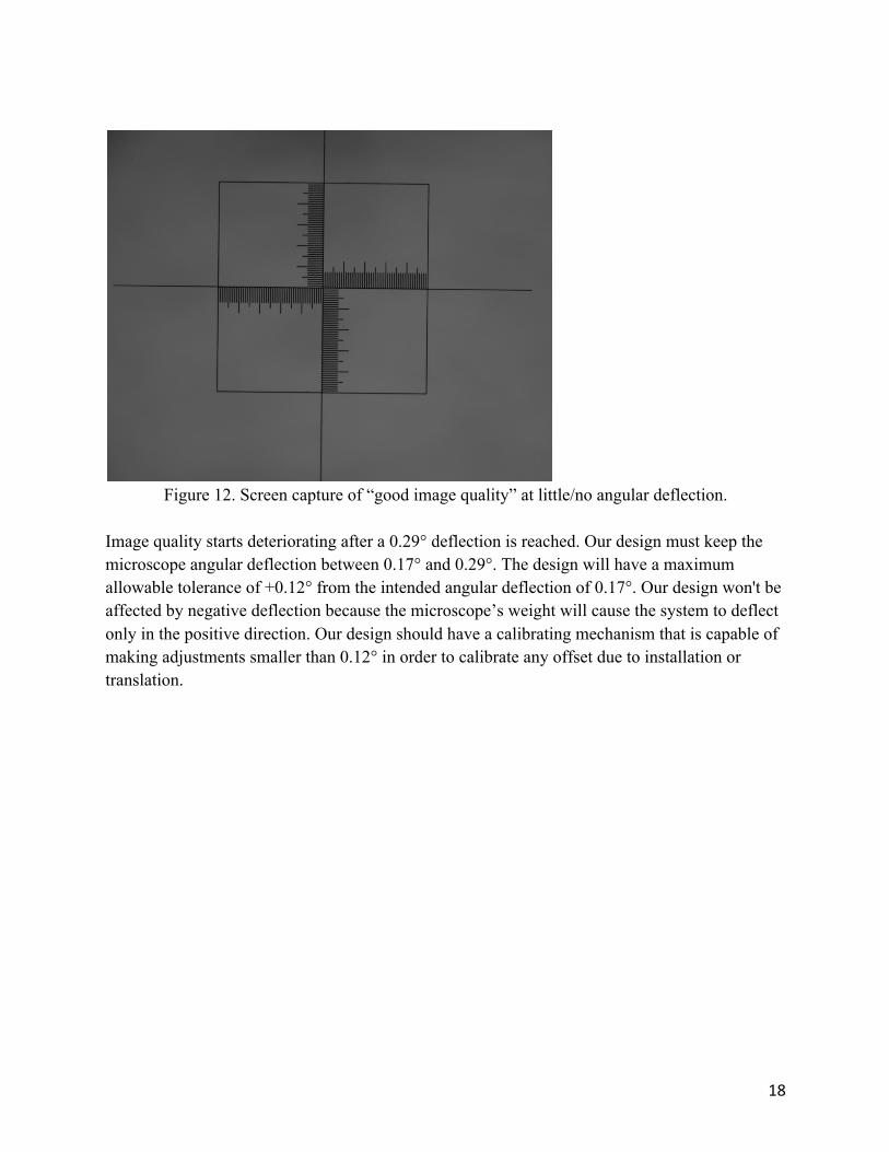
Figure 12. Screen capture of “good image quality” at little/no angular deflection.
Image quality starts deteriorating after a 0.29° deflection is reached. Our design must keep the microscope angular deflection between 0.17° and 0.29°. The design will have a maximum allowable tolerance of +0.12° from the intended angular deflection of 0.17°. Our design won't be affected by negative deflection because the microscope’s weight will cause the system to deflect only in the positive direction. Our design should have a calibrating mechanism that is capable of making adjustments smaller than 0.12° in order to calibrate any offset due to installation or translation.
19
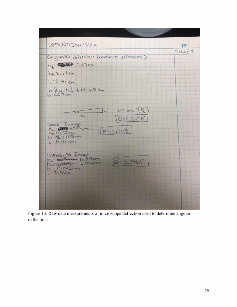
Figure 13. Raw data measurements of microscope deflection used to determine angular deflection.

20
6.2 Evolution of PrototypesDocking SystemThis system was designed to allow changes in deflection and calibration. The design features a rotating part installed onto the microscope, housed by a dock which would be installed onto the support system. This allows the deflection angle to be changed and secured at 0.17°. The rotating part would feature a gear system that would allow for locking of the gears every 0.05° rotated. This is sufficient accuracy to calibrate the deflection angle between the working range of the microscope (0.17°-0.29°).Our next steps for this docking system prototype is to do some material testing to make sure that the material will shift within our tolerance of deflection. We also plan on adding a new L-bar with more support to reduce the possibility or amount of deflection that occurs, including adding a docking spot for a jack that will allow for minor adjustments to the bar. These modifications should fix the angular deflection that Dr. Cardinal and his lab team have been having issues with.This component was not included in the final design because a machinist jack was a more ideal candidate for the adjustable component of the design.L-BarIn order to eliminate the deflection at the pivot joint, a new support section can be implemented at the joint between the z-translation bar and the radially-extending bar of the microscope stand. A rigid L-bar should only allow deflection due to bending of the material itself, so the next step for this component of the project is to continue research to determine an ideal stiffness and elastic modulus of the material considering the weight of the microscope (17 kg). If the rigid L-bar is designed so that it does not deflect under the weight of the microscope (17 kg), ideally there should be no deflection of the compound microscope.After looking more into the design, we finalized our prototype to only have the L-bar, and integrate with the current vertical member on the microscope to reduce cost and create as little change as possible within Dr. Cardinal’s research lab. We determined that the best material to use for the L-bar would be aluminum because of its high yield strength and low weight. We simplified our SolidWorks model during manufacturing to not have the vertical stopper.
6.3 Manufacturing Process1. Using horizontal band-saw, cut 24” x 5” x 2” aluminum block into three 8” x 5” x 2”
pieces. 2. Using vertical band-saw cut 2.25” (perpendicular to 8” side) x 6.5” (perpendicular to 5”
side) piece out of 8” x 5” x 2” piece. These cuts form an “L” shape from the 8” x 5” x 2” block.
3. Using mill, increase cut to 2.75” (perpendicular to 8” side) x 6.9” (perpendicular to 5” side) piece out of “L” shaped block.
21
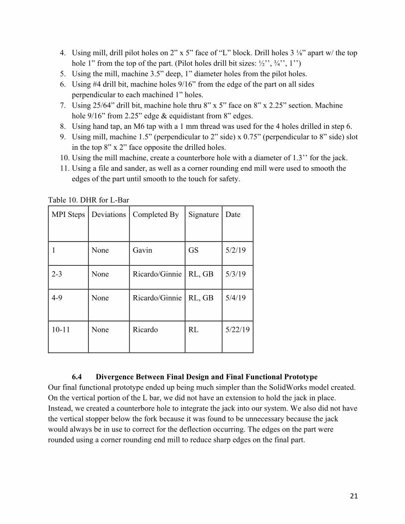
4. Using mill, drill pilot holes on 2” x 5” face of “L” block. Drill holes 3 ⅛” apart w/ the top hole 1” from the top of the part. (Pilot holes drill bit sizes: ½’’, ¾’’, 1’’)
5. Using the mill, machine 3.5” deep, 1” diameter holes from the pilot holes. 6. Using #4 drill bit, machine holes 9/16” from the edge of the part on all sides
perpendicular to each machined 1” holes. 7. Using 25/64” drill bit, machine hole thru 8” x 5” face on 8” x 2.25” section. Machine
hole 9/16” from 2.25” edge & equidistant from 8” edges. 8. Using hand tap, an M6 tap with a 1 mm thread was used for the 4 holes drilled in step 6. 9. Using mill, machine 1.5” (perpendicular to 2” side) x 0.75” (perpendicular to 8” side) slot
in the top 8” x 2” face opposite the drilled holes. 10. Using the mill machine, create a counterbore hole with a diameter of 1.3’’ for the jack. 11. Using a file and sander, as well as a corner rounding end mill were used to smooth the
edges of the part until smooth to the touch for safety. Table 10. DHR for L-Bar
MPI Steps Deviations Completed By Signature Date
1 None Gavin GS 5/2/19
2-3 None Ricardo/Ginnie RL, GB 5/3/19
4-9 None Ricardo/Ginnie RL, GB 5/4/19
10-11 None Ricardo RL 5/22/19
6.4 Divergence Between Final Design and Final Functional PrototypeOur final functional prototype ended up being much simpler than the SolidWorks model created. On the vertical portion of the L bar, we did not have an extension to hold the jack in place. Instead, we created a counterbore hole to integrate the jack into our system. We also did not have the vertical stopper below the fork because it was found to be unnecessary because the jack would always be in use to correct for the deflection occurring. The edges on the part were rounded using a corner rounding end mill to reduce sharp edges on the final part.
22
7.0 IQ/OQ/PQ
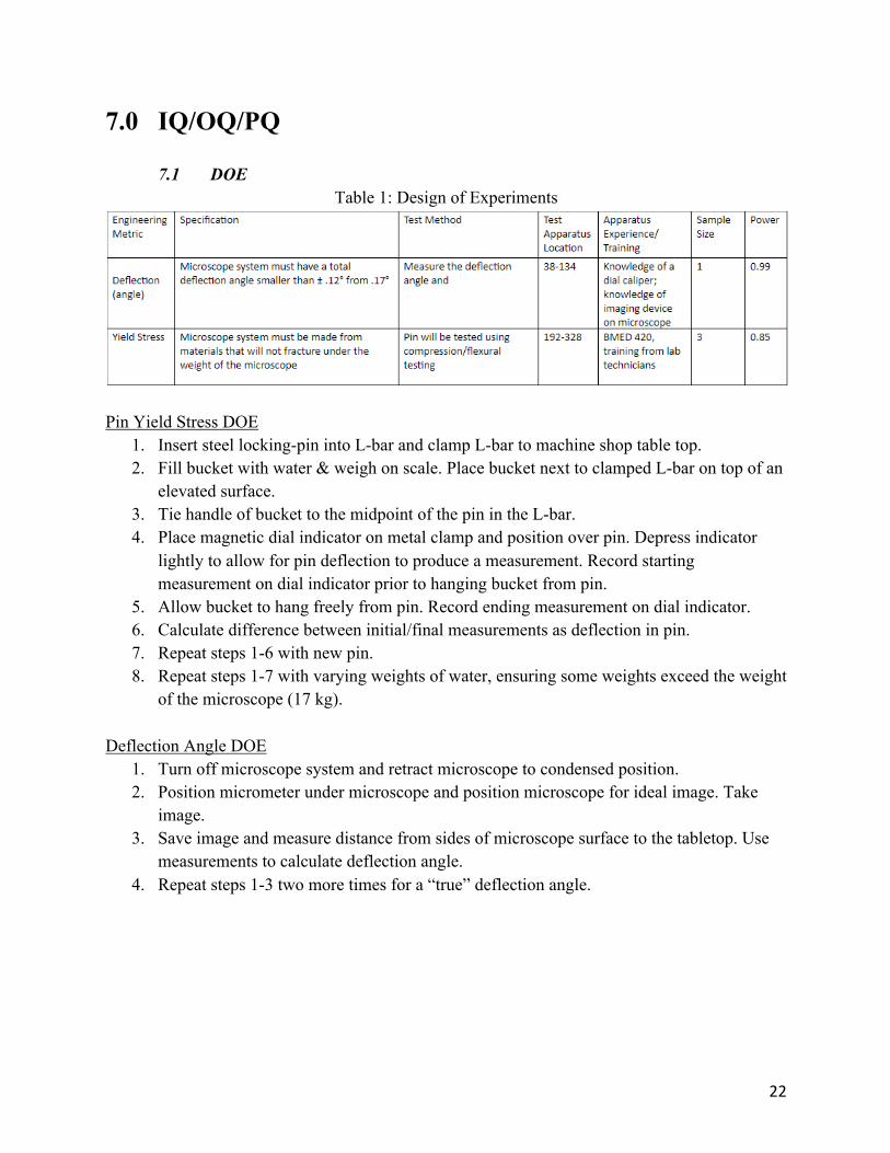
7.1 DOETable 1: Design of Experiments
Pin Yield Stress DOE
1. Insert steel locking-pin into L-bar and clamp L-bar to machine shop table top. 2. Fill bucket with water & weigh on scale. Place bucket next to clamped L-bar on top of an
elevated surface. 3. Tie handle of bucket to the midpoint of the pin in the L-bar. 4. Place magnetic dial indicator on metal clamp and position over pin. Depress indicator
lightly to allow for pin deflection to produce a measurement. Record starting measurement on dial indicator prior to hanging bucket from pin.
5. Allow bucket to hang freely from pin. Record ending measurement on dial indicator. 6. Calculate difference between initial/final measurements as deflection in pin. 7. Repeat steps 1-6 with new pin. 8. Repeat steps 1-7 with varying weights of water, ensuring some weights exceed the weight
of the microscope (17 kg). Deflection Angle DOE
1. Turn off microscope system and retract microscope to condensed position. 2. Position micrometer under microscope and position microscope for ideal image. Take
image. 3. Save image and measure distance from sides of microscope surface to the tabletop. Use
measurements to calculate deflection angle. 4. Repeat steps 1-3 two more times for a “true” deflection angle.
23
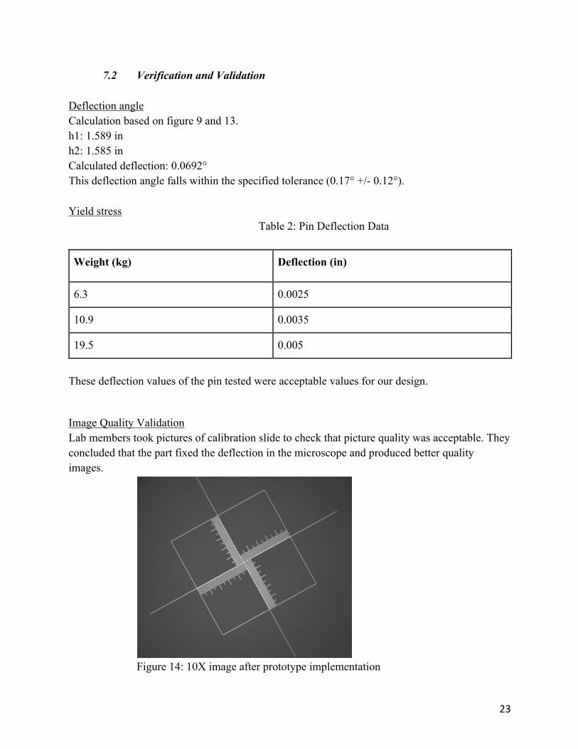
7.2 Verification and ValidationDeflection angleCalculation based on figure 9 and 13.h1: 1.589 inh2: 1.585 inCalculated deflection: 0.0692°This deflection angle falls within the specified tolerance (0.17° +/- 0.12°).Yield stress
Table 2: Pin Deflection Data
Weight (kg) Deflection (in)
6.3 0.0025
10.9 0.0035
19.5 0.005
These deflection values of the pin tested were acceptable values for our design.
Image Quality ValidationLab members took pictures of calibration slide to check that picture quality was acceptable. They concluded that the part fixed the deflection in the microscope and produced better quality images.
Figure 14: 10X image after prototype implementation

24
8.0 Conclusions and Recommendations
8.1 RecommendationsOur recommendations for Dr. Cardinal’s lab is to keep the jack within the allotted tolerance. The microscope system should only be adjusted when it is completely necessary, and should be done under the supervision of Dr. Trevor Cardinal or another lab leader.
8.2 ConclusionsThe manufactured part and accompanying steel locking pin corrected the deflection of the compound microscope in Dr. Cardinal’s lab and did not drastically change the previous microscope system. The improved microscope stand allows lab members to consistently acquire quality images on the Olympus Compound Microscope when performing in vivo measurements on the diameter of mouse hindlimb collaterals.

25
9.0 AcknowledgementsWe would like to acknowledge Dr. Michael Whitt, Professor Gerrity, Dr. Trevor Cardinal and his team, Professor Kevin Williams, and Kevin Chouinard for their assistance on this project. Without their guidance, this project would not have been possible.
26
10. Appendices
10.1 Appendix A: References
[1] "3.5-225X Trinocular Articulating Arm Pillar Clamp 144-LED Zoom Stereo Microscope." amscope.com, www.amscope.com/3-5x-225x-trinocular-articulating-arm-pillar-clamp-144-led-zoom-stereo-microscope.html?medium=tsa&gclid=Cj0KCQiAj4biBRC-ARIsAA4WaFibtuh3Oy6AQ1N9zCCP3QCXpSzFID3C4VyrF-Jr9AKhkPwf.
[2] "20X-30X-40X-60X Stereo Microscope on Single-Arm Boom with Ring Light SKU: SW-3B24Y-FRL." amscope.com, www.amscope.com/20x-30x-40x-60x-stereo-microscope-on-single-arm-boom-with-ring-light.html?medium=tsa&gclid=Cj0KCQiAj4biBRC-ARIsAA4WaFj7-l705f7RUuH7QbPjxFsP_nE5PJacwuX2JE1wZE33Gwh6gpr7gXMaAigKE.
[3] "Articulating Arm with Base Plate for Stereo Microscopes." amscope.com, www.amscope.com/articulating-arm-with-base-plate-for-stereo-microscopes.html?medium=tsa&gclid=Cj0KCQiAj4biBRC-ARIsAA4WaFjf57CoaZxPPrg6sRPZVr6EXJpUA9IwVtEfj7eGQXipud_pXt5XaG4aAj1gEALw_wcB&gclsr.
[4] "40X-1600X Five-Observing Compound Microscope." amscope.com, www.amscope.com/five-observing-compound-microscope-40x-1600x.html?medium=tsa&gclid=Cj0KCQiAj4biBRC-ARIsAA4WaFgxOywCuYvUUaZJpKwZYlMmoiVsCcg7FDijtubUXLVBd5OiDrrZ04caAhRaEALw_wcB&gclsrc=aw.ds.
[5] Dourmashkin, Robert R., and Wendell F. Rosse. "Morphologic changes in the membranes of red blood cells undergoing hemolysis." The American Journal of Medicine, doi:https://doi.org/10.1016/0002-9343(66)90031-3, www.amjmed.com/article/0002-9343(66)90031-3/fulltext.
[6] Chen, PhD, Qin M., and Joseph S. Alpert. "To Supplement or Not: A Role for Antioxidant Vitamins in the Management of Heart Failure?" The American Journal of Medicine, doi:https://doi.org/10.1016/j.amjmed.2016.02.048, www.amjmed.com/article/S0002-9343(16)30319-9/fulltext.
[7] Prien, PhD, Edwin L., and Edwin L. Prien Jr., M.D. "Composition and structure of urinary stone." The American Journal of Medicine, doi:https://doi.org/10.1016/0002-9343(68)90202-7, www.amjmed.com/article/0002-9343(68)90202-7/fulltext.

27
[8] Remmer, M.D., H. "The role of the liver in drug metabolism." The American Journal of Medicine, doi:https://doi.org/10.1016/S0002-9343(70)80129-2, www.amjmed.com/article/S0002-9343(70)80129-2/fulltext.
[9] Wands, Jack R. "Chronic inorganic mercury poisoning due to laxative abuse." The American Journal of Medicine, doi:https://doi.org/10.1016/0002-9343(74)90773-6, www.amjmed.com/article/0002-9343(74)90773-6/fulltext.

28
10.2 Appendix B: Project Plan (PERT Chart)
Figure 15. A) Gantt Chart and B) PERT chart for microscope project.

29
10.3 Appendix C: CAD Drawings
Figure 16: Housing Concept 1
Figure 17: Rotator Concept 1
30
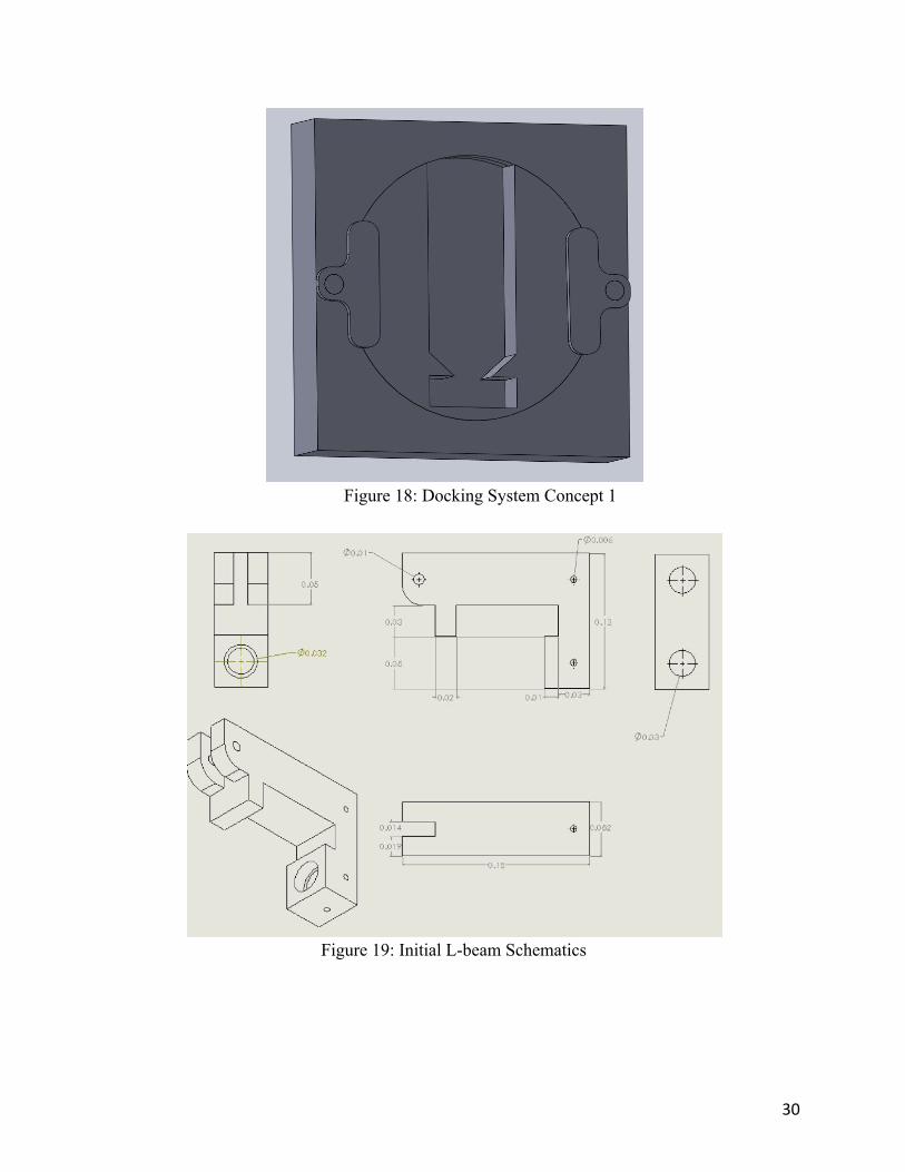
Figure 18: Docking System Concept 1
Figure 19: Initial L-beam Schematics

31
Figure 20: Final L-beam Model
32
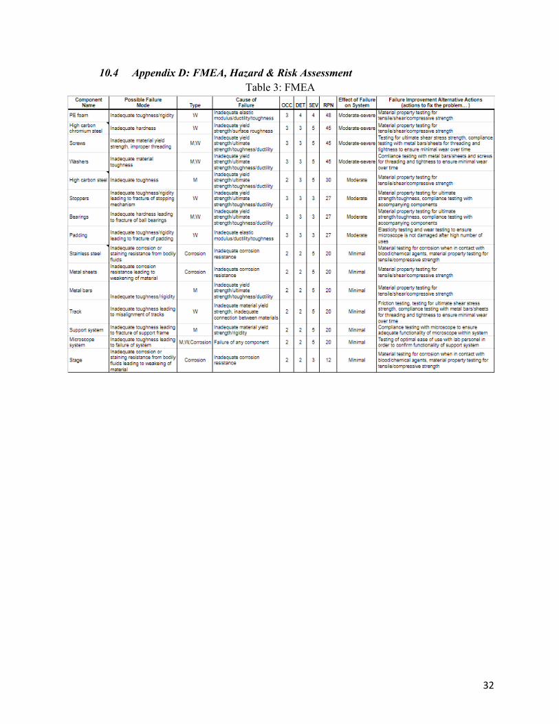
10.4 Appendix D: FMEA, Hazard & Risk AssessmentTable 3: FMEA
33
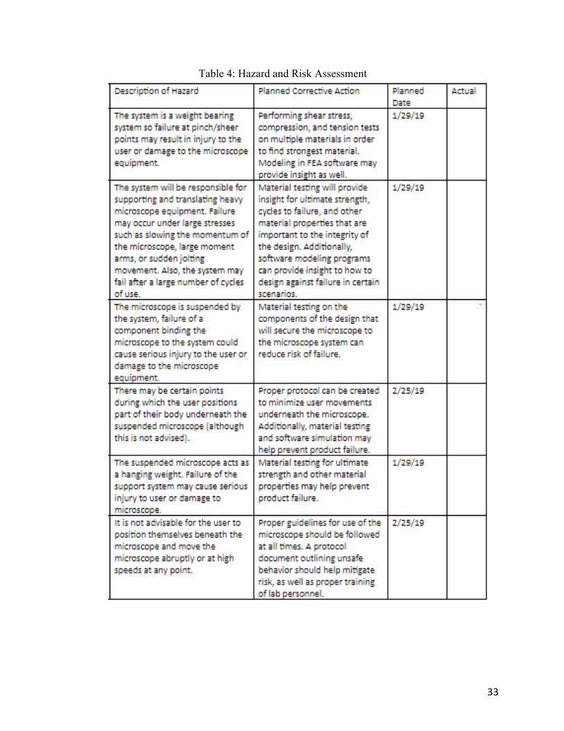
Table 4: Hazard and Risk Assessment
34
10.5 Appendix E: Pugh Chart
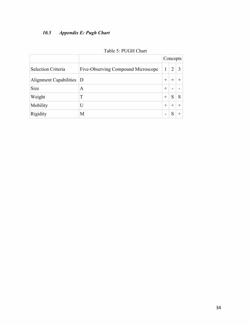
Table 5: PUGH Chart
Concepts
Selection Criteria Five-Observing Compound Microscope 1 2 3
Alignment Capabilities D + + +
Size A + - -
Weight T + S S
Mobility U + + +
Rigidity M - S +
35
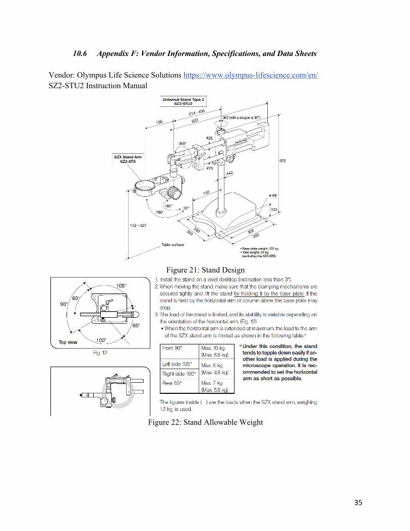
10.6 Appendix F: Vendor Information, Specifications, and Data SheetsVendor: Olympus Life Science Solutions https://www.olympus-lifescience.com/en/SZ2-STU2 Instruction Manual
Figure 21: Stand Design
Figure 22: Stand Allowable Weight

36
10.7 Appendix G: Budget
Table 6: Budget
Item Description Product Number Source
Planned
Quantity Cost/Unit Total Cost Notes
Zinc-Plated Steel Locking Pin 98416A019 McMaster-
Carr 3 $2.28 $6.84 Aluminum Rectangle Bar
6061-T6511 Extruded 17681 Online Metals 1 $115.72 $147.25 2"x5"x24"
Total $118.00 $154.09
37
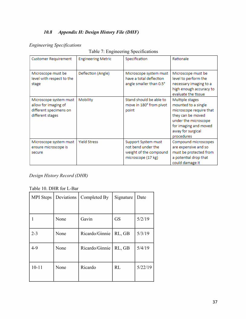
10.8 Appendix H: Design History File (DHF)Engineering Specifications
Table 7: Engineering Specifications
Design History Record (DHR)Table 10. DHR for L-Bar
MPI Steps Deviations Completed By Signature Date
1 None Gavin GS 5/2/19
2-3 None Ricardo/Ginnie RL, GB 5/3/19
4-9 None Ricardo/Ginnie RL, GB 5/4/19
10-11 None Ricardo RL 5/22/19

38
Docking System:This system was designed to allow changes in deflection and calibration. The design features a rotating part installed onto the microscope, housed by a dock which would be installed onto the support system. This allows the deflection angle to be changed and secured at 0.17°. The rotating part would feature a gear system that would allow for locking of the gears every 0.05° rotated. This is sufficient accuracy to calibrate the deflection angle between the working range of the microscope (0.17°-0.29°).Our next steps for this docking system prototype is to do some material testing to make sure that the material will shift within our tolerance of deflection. We also plan on adding a new L-bar with more support to reduce the possibility or amount of deflection that occurs, including adding a docking spot for a jack that will allow for minor adjustments to the bar. These modifications should fix the angular deflection that Dr. Cardinal and his lab team have been having issues with. L-Bar:In order to eliminate the deflection at the pivot joint, a new support section can be implemented at the joint between the z-translation bar and the radially-extending bar of the microscope stand. A rigid L-bar should only allow deflection due to bending of the material itself, so the next step for this component of the project is to continue research to determine an ideal stiffness and elastic modulus of the material considering the weight of the microscope (17 kg). If the rigid L-bar is designed so that it does not deflect under the weight of the microscope (17 kg), ideally there should be no deflection of the compound microscope.Manufacturing Process Instructions (MPI)
1. Using horizontal band-saw,cut 24” x 5” x 2”aluminum block into three 8” x 5” x 2” pieces.
2. Using vertical band-saw cut 2.25” (perpendicular to 8” side) x 6.5” (perpendicular to 5” side) piece out of 8” x 5” x 2” piece. These cuts form an “L” shape from the 8” x 5” x 2” block.
3. Using mill, increase cut to 2.75” (perpendicular to 8” side) x 6.9” (perpendicular to 5” side) piece out of “L” shape block.
4. Using mill, drill pilot holes on 2” x 5” face of “L” block. Drill holes 3 1⁄8” apart w/ the top hole 1” from the top of the part. (Pilot holes drill bit sizes: 1⁄2’’, 3⁄4’’, 1’’)
5. Using the mill, machine 3.5” deep, 1” diameter holes from the pilot holes. 6. Using #4 drill bit, machine holes 9/16” from the edge of the part on all sides
perpendicular to each machined 1” holes. 7. Using 25/64” drill bit, machine hole thru 8” x 5” face on 8” x 2.25” section. Machine
hole 9/16” from 2.25” edge & equidistant from 8” edges. 8. Using hand tap, an M6 tap with a 1 mm thread was used for the 4 holes drilled in step 6. 9. Using mill, machine 1.5”(perpendicular to 2” side) x 0.75” (perpendicular to 8” side) slot
in the top 8” x 2” face opposite the drilled holes.
39
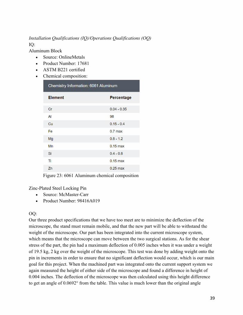
Installation Qualifications (IQ)/Operations Qualifications (OQ)IQ:Aluminum Block
• Source: OnlineMetals • Product Number: 17681 • ASTM B221 certified • Chemical composition:
Figure 23: 6061 Aluminum chemical composition
Zinc-Plated Steel Locking Pin
• Source: McMaster-Carr • Product Number: 98416A019
OQ:Our three product specifications that we have too meet are to minimize the deflection of the microscope, the stand must remain mobile, and that the new part will be able to withstand the weight of the microscope. Our part has been integrated into the current microscope system, which means that the microscope can move between the two surgical stations. As for the shear stress of the part, the pin had a maximum deflection of 0.005 inches when it was under a weight of 19.5 kg, 2 kg over the weight of the microscope. This test was done by adding weight onto the pin in increments in order to ensure that no significant deflection would occur, which is our main goal for this project. When the machined part was integrated onto the current support system we again measured the height of either side of the microscope and found a difference in height of 0.004 inches. The deflection of the microscope was then calculated using this height difference to get an angle of 0.0692° from the table. This value is much lower than the original angle
40
measured (0.17°). This is the key test for our design because the clarity of the images taken is directly related to how much deflection occurs. We needed the deflection of the microscope to be within the initial tolerances (0.17° +/- 0.12°) found when determining what was a “good” and “bad” quality image in order to consider our design a success.
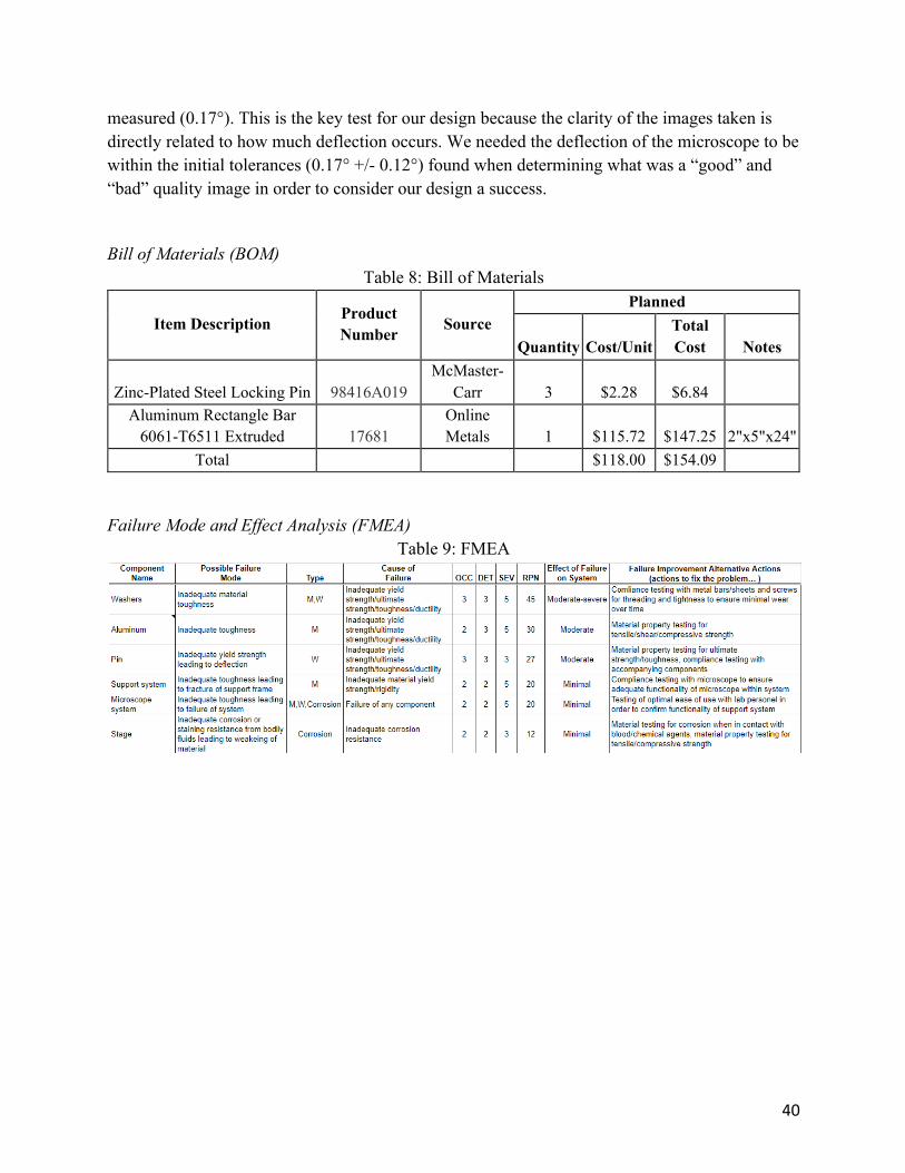
Bill of Materials (BOM)Table 8: Bill of Materials
Item Description Product Number Source
Planned
Quantity Cost/Unit Total Cost Notes
Zinc-Plated Steel Locking Pin 98416A019 McMaster-
Carr 3 $2.28 $6.84 Aluminum Rectangle Bar
6061-T6511 Extruded 17681 Online Metals 1 $115.72 $147.25 2"x5"x24"
Total $118.00 $154.09
Failure Mode and Effect Analysis (FMEA)Table 9: FMEA