noiseblock install
DESCRIPTION
Noise ControlTRANSCRIPT
INS-Enclosures Rev.0 (2014-08-05)
6300 Irelan Place, Dublin OH 43017, ph. 614-889-0480 1670 Bishop Street North, Cambridge ON, Canada, N1R 7J3, ph. 905-670-4922
INSTRUCTIONS AND GUIDELINES
NOISEBLOCKTM MODULAR PANEL SYSTEMS
ENCLOSURES & PRESSURIZED PLENUMS
INS-Enclosures Rev.0 (2014-08-05)
6300 Irelan Place, Dublin OH 43017, ph. 614-889-0480 1670 Bishop Street North, Cambridge ON, Canada, N1R 7J3, ph. 905-670-4922
PLANNING HINTS & NOTES: 1. Review the Kinetics Noise Control submittal and installation drawings and bill of material.
2. The bill of material contains a complete list of pieces and parts supplied by Kinetics Noise
Control including panels, trim (flashing) and miscellaneous hardware. Each part number corresponds to a piece-marked item on the installation drawing.
3. Before the delivery of panels arrives, clear an area near where the panels are to be
assembled. To save time and labor in handling the panels, unload the panels directly from the truck to this area. Make sure the necessary material handling equipment is available, including lifts for getting the panels off the truck and the proper floor carts to move the panels.
4. When panels are stored near the installation area, stack them on end and lengthwise. This
will save time moving and restacking panels as the NOISEBLOCKTM enclosure is assembled. If more than one enclosure is involved, separate and stack the panels by drawing number, which can be found on the label on the end of each panel.
5. Assemble a complete set of tools and equipment required to install the panel system.
Depending on the nature of the job, the following items may be required:
• Welding and cutting equipment • Ladder • Extension cord • Drill masters & self-drilling driving head • Lifts • Portable lighting
• Masonry drills • Metal cutting saws • Steel tape measure • Come-a-long • Sealer gun
GENERAL NOTES:
1. Where sealant is called for on the piece-marked, installation drawings use a ¼ inch bead of
sealant to properly seal joints. Kinetics Noise Control supplies the sealer with each enclosure system shipment. This sealer is used at the base channel, outside trim, panel joints, and where shown on the installation drawings. Kinetics Noise Control will provide the quantity of sealer supplied is approximately equal to the total linear feet of all panel system trim, roof panel joints and wall joints divided by 20. This amount should be adequate, but KNC does not guarantee that the quantity will be enough for any specific job or installing contractor.
2. All base channel and outside trim is supplied in standard 10 foot lengths to be field cut to size
during installation. Sheet metal screws are supplied with each panel system. Kinetics Noise Control will provide a quantity of TEKS 4 (sometimes TEKS 5 are specified) sheet metal fasteners to approximately 5 times the total lineal feet of all panel system trim and base channel. This
INS-Enclosures Rev.0 (2014-08-05)
6300 Irelan Place, Dublin OH 43017, ph. 614-889-0480 1670 Bishop Street North, Cambridge ON, Canada, N1R 7J3, ph. 905-670-4922
number should be adequate, but KNC does not guarantee that it will be enough for any specific job or installing contractor.
SUMMARY OF INSTALLATION
1. Locate base channel 2. Set corner panels 3. Install wall, partition and door panels 4. Add wall trim – outside and inside 5. Structural steel (as required) 6. Add roof panels 7. Add roof trim – inside and outside 8. Completed enclosure
STEP 1: INSTALLATION OF BASE CHANNEL
A. Check grade/floor/curb/base to ensure it is square, level, and in
accordance with the approved dimensions. Problems may arise later if the curb is not properly installed or grade not properly level.
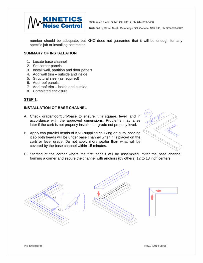
B. Apply two parallel beads of KNC supplied caulking on curb, spacing it so both beads will be under base channel when it is placed on the curb or level grade. Do not apply more sealer than what will be covered by the base channel within 15 minutes.
C. Starting at the corner where the first panels will be assembled, miter the base channel,
forming a corner and secure the channel with anchors (by others) 12 to 18 inch centers.
x2
x2
INS-Enclosures Rev.0 (2014-08-05)
6300 Irelan Place, Dublin OH 43017, ph. 614-889-0480 1670 Bishop Street North, Cambridge ON, Canada, N1R 7J3, ph. 905-670-4922
12" - 18"(305 mm - 457 mm)
CL
CL
CL= =
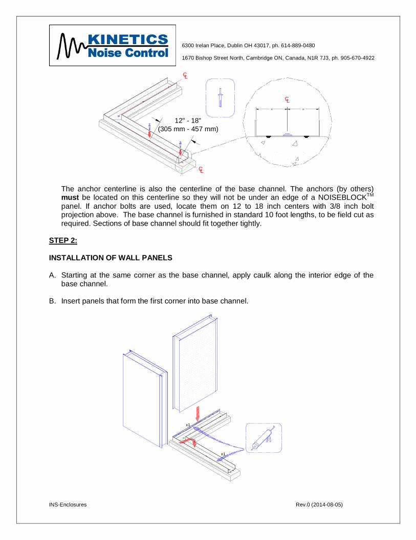
The anchor centerline is also the centerline of the base channel. The anchors (by others) must be located on this centerline so they will not be under an edge of a NOISEBLOCKTM panel. If anchor bolts are used, locate them on 12 to 18 inch centers with 3/8 inch bolt projection above. The base channel is furnished in standard 10 foot lengths, to be field cut as required. Sections of base channel should fit together tightly.
STEP 2: INSTALLATION OF WALL PANELS
A. Starting at the same corner as the base channel, apply caulk along the interior edge of the
base channel.
B. Insert panels that form the first corner into base channel.
x1
x1
INS-Enclosures Rev.0 (2014-08-05)
6300 Irelan Place, Dublin OH 43017, ph. 614-889-0480 1670 Bishop Street North, Cambridge ON, Canada, N1R 7J3, ph. 905-670-4922
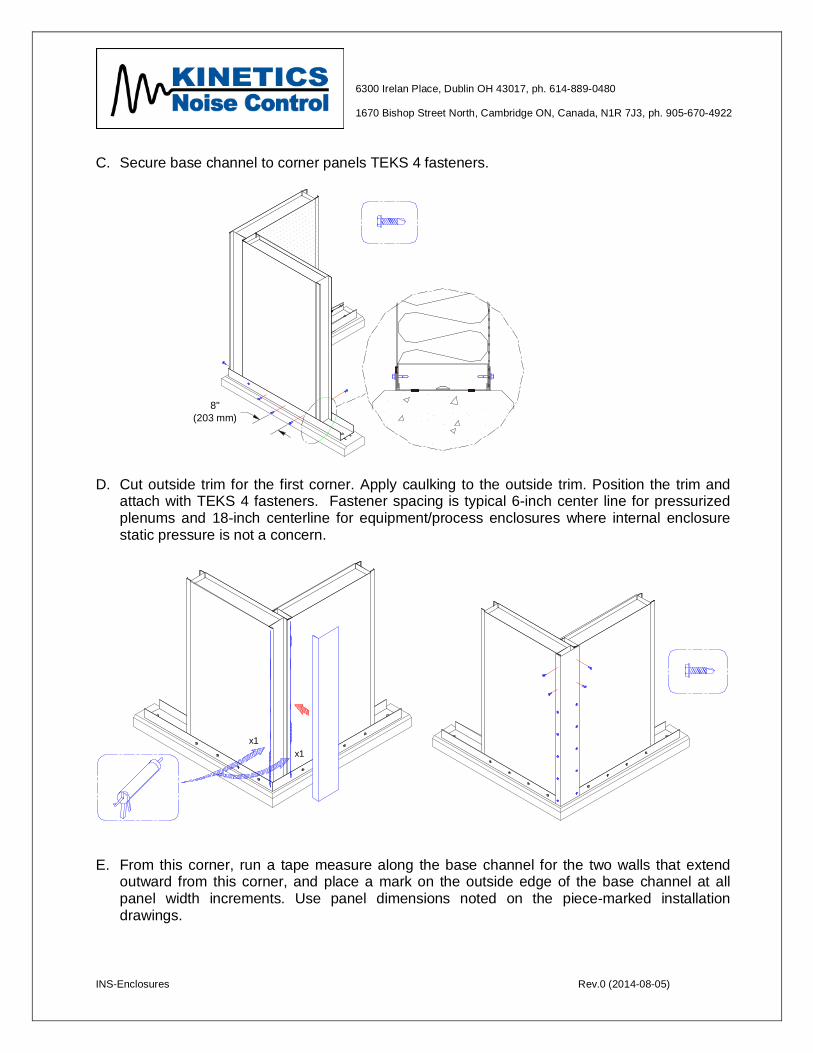
C. Secure base channel to corner panels TEKS 4 fasteners.
8"(203 mm)
D. Cut outside trim for the first corner. Apply caulking to the outside trim. Position the trim and attach with TEKS 4 fasteners. Fastener spacing is typical 6-inch center line for pressurized plenums and 18-inch centerline for equipment/process enclosures where internal enclosure static pressure is not a concern.
x1x1
E. From this corner, run a tape measure along the base channel for the two walls that extend
outward from this corner, and place a mark on the outside edge of the base channel at all panel width increments. Use panel dimensions noted on the piece-marked installation drawings.
INS-Enclosures Rev.0 (2014-08-05)
6300 Irelan Place, Dublin OH 43017, ph. 614-889-0480 1670 Bishop Street North, Cambridge ON, Canada, N1R 7J3, ph. 905-670-4922
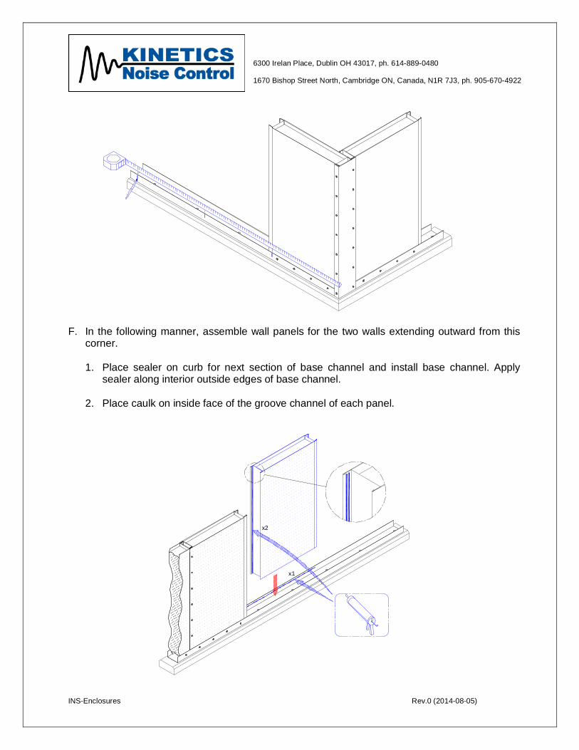
F. In the following manner, assemble wall panels for the two walls extending outward from this corner.
1. Place sealer on curb for next section of base channel and install base channel. Apply
sealer along interior outside edges of base channel.
2. Place caulk on inside face of the groove channel of each panel.
x2
x1
INS-Enclosures Rev.0 (2014-08-05)
6300 Irelan Place, Dublin OH 43017, ph. 614-889-0480 1670 Bishop Street North, Cambridge ON, Canada, N1R 7J3, ph. 905-670-4922
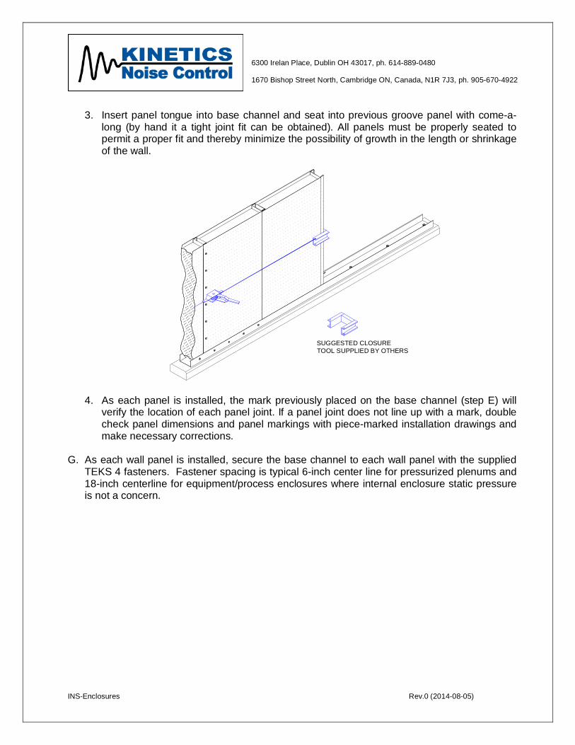
3. Insert panel tongue into base channel and seat into previous groove panel with come-a-
long (by hand it a tight joint fit can be obtained). All panels must be properly seated to permit a proper fit and thereby minimize the possibility of growth in the length or shrinkage of the wall.
SUGGESTED CLOSURETOOL SUPPLIED BY OTHERS
4. As each panel is installed, the mark previously placed on the base channel (step E) will verify the location of each panel joint. If a panel joint does not line up with a mark, double check panel dimensions and panel markings with piece-marked installation drawings and make necessary corrections.
G. As each wall panel is installed, secure the base channel to each wall panel with the supplied TEKS 4 fasteners. Fastener spacing is typical 6-inch center line for pressurized plenums and 18-inch centerline for equipment/process enclosures where internal enclosure static pressure is not a concern.
INS-Enclosures Rev.0 (2014-08-05)
6300 Irelan Place, Dublin OH 43017, ph. 614-889-0480 1670 Bishop Street North, Cambridge ON, Canada, N1R 7J3, ph. 905-670-4922
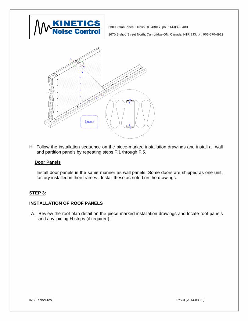
H. Follow the installation sequence on the piece-marked installation drawings and install all wall and partition panels by repeating steps F.1 through F.5.
Door Panels Install door panels in the same manner as wall panels. Some doors are shipped as one unit, factory installed in their frames. Install these as noted on the drawings.
STEP 3: INSTALLATION OF ROOF PANELS
A. Review the roof plan detail on the piece-marked installation drawings and locate roof panels
and any joining H-strips (if required).
INS-Enclosures Rev.0 (2014-08-05)
6300 Irelan Place, Dublin OH 43017, ph. 614-889-0480 1670 Bishop Street North, Cambridge ON, Canada, N1R 7J3, ph. 905-670-4922
x2
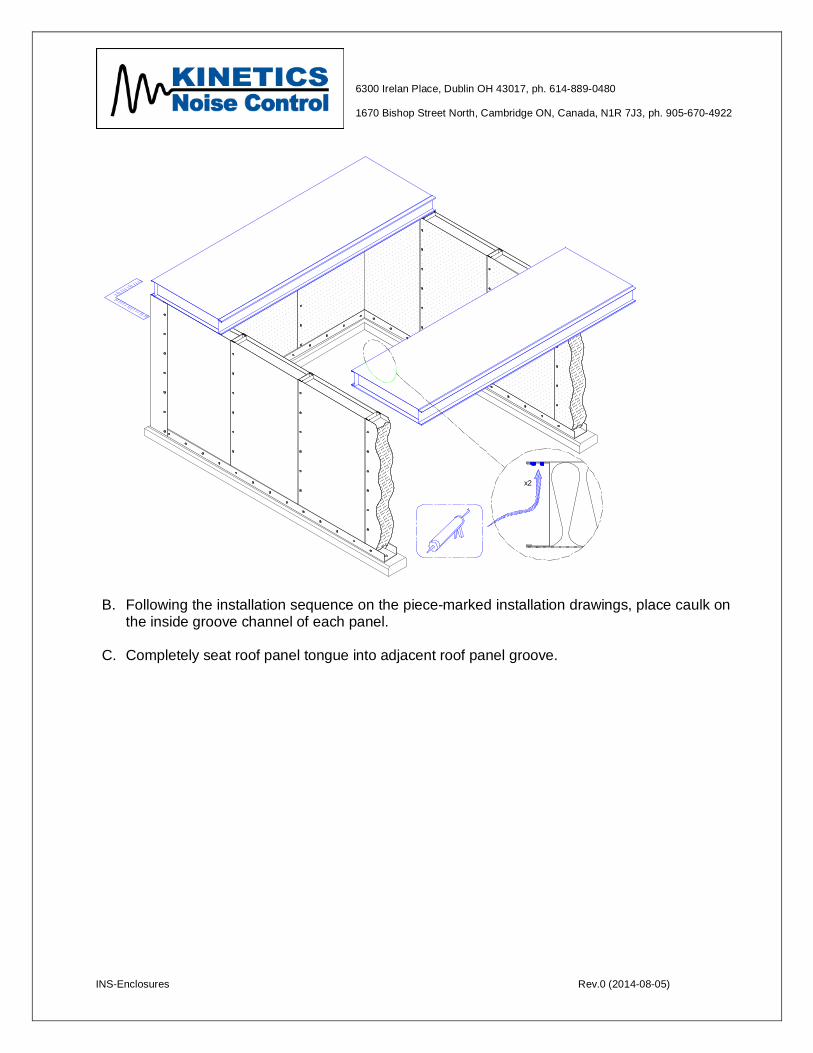
B. Following the installation sequence on the piece-marked installation drawings, place caulk on
the inside groove channel of each panel.
C. Completely seat roof panel tongue into adjacent roof panel groove.
INS-Enclosures Rev.0 (2014-08-05)
6300 Irelan Place, Dublin OH 43017, ph. 614-889-0480 1670 Bishop Street North, Cambridge ON, Canada, N1R 7J3, ph. 905-670-4922
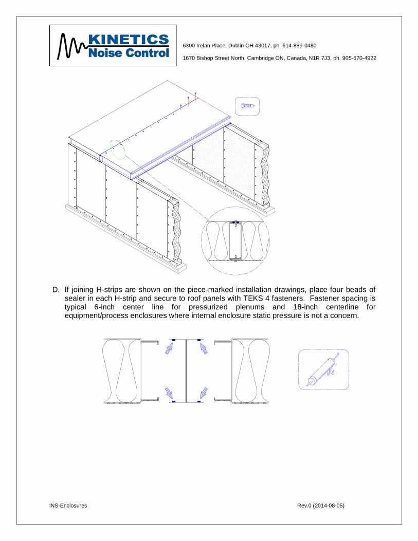
D. If joining H-strips are shown on the piece-marked installation drawings, place four beads of sealer in each H-strip and secure to roof panels with TEKS 4 fasteners. Fastener spacing is typical 6-inch center line for pressurized plenums and 18-inch centerline for equipment/process enclosures where internal enclosure static pressure is not a concern.
INS-Enclosures Rev.0 (2014-08-05)
6300 Irelan Place, Dublin OH 43017, ph. 614-889-0480 1670 Bishop Street North, Cambridge ON, Canada, N1R 7J3, ph. 905-670-4922
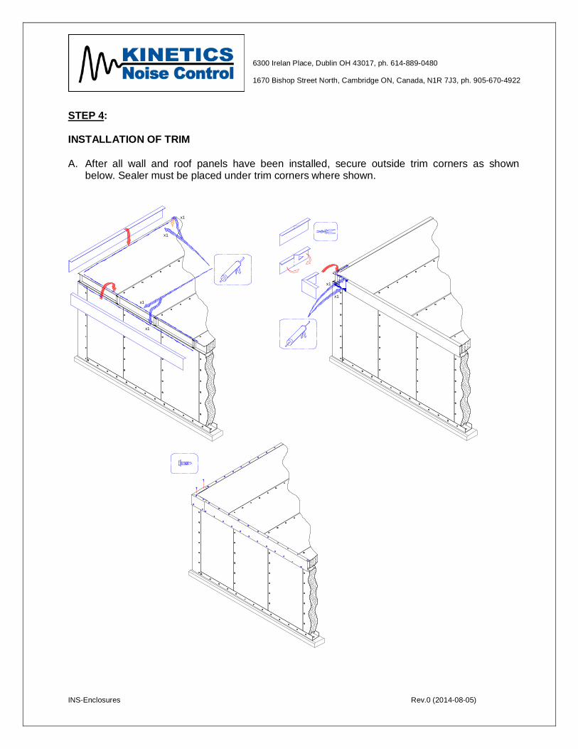
STEP 4: INSTALLATION OF TRIM A. After all wall and roof panels have been installed, secure outside trim corners as shown
below. Sealer must be placed under trim corners where shown.
x1
x1
x1
x1
x1
x1

INS-Enclosures Rev.0 (2014-08-05)
6300 Irelan Place, Dublin OH 43017, ph. 614-889-0480 1670 Bishop Street North, Cambridge ON, Canada, N1R 7J3, ph. 905-670-4922
B. Cut all outside trim (panel corners and panel-to-roof corners) to proper dimensions, apply
sealer, position trim, and attach with TEKS 4 fasteners. Outside trim is shipped in standard 10 foot lengths to be field cut as required.
C. After all outside trim has been installed, finish by installing inside trim at wall-to-wall and wall-
to-roof corners. The inside trim is shipped in standard 10 foot lengths to be cut in the field as required. The installing contractor must drill and anchor inside trim at all tongue and groove panel joints and at all internal panel stiffeners.
SPECIAL ASSEMBLY CONSIDERATIONS FACTORY OPENINGS
If a factory opening is required, a channel will have been factory installed inside the panel edge adjacent to the opening to retain (safe-off) the acoustic grade fill.
STRUCTURAL SUPPORT STEEL
If roof plans are greater than 12 feet, external, structural steel bracing may be required. If so, the external, structural steel will be detailed on the Kinetics Noise Control piece-marked installation drawings and should be installed according to be instructions.