nuclear power corporation of india limited … · (a government of india enterprise) madras atomic...
TRANSCRIPT
NUCLEAR POWER CORPORATION OF INDIA LIMITED (A Government of India Enterprise)
MADRAS ATOMIC POWER STATION KALPAKKAM
TENDER SPECIFICATION FOR
MICOM P343, P643, P142 RELAY SPECIFICATION
14 July 2015
Nuclear Power Corporation of India Limited Madras Atomic Power Station
Electrical Maintenance
Tender Specification for MICOM P343, P643, P142 RELAY SPECIFICATION Page 1 of 24
CONTENTS
S.No. Description Page Nos.
Generator Protection Relay Micom Series P343 Relay Specification
2 to 9
Transformer protection relay MICOM series P643 relay specification 10 to 14
Feeder management relay, MICOM series p142 relay specification 15 to 20
4.0 Documentation 20 5.0 Type test certificates 21 6.0 Electromagnetic Compatibility 22
7.0 Routine test in the presence of inspection engineer from site
24
Nuclear Power Corporation of India Limited Madras Atomic Power Station
Electrical Maintenance
Tender Specification for MICOM P343, P643, P142 RELAY SPECIFICATION Page 2 of 24
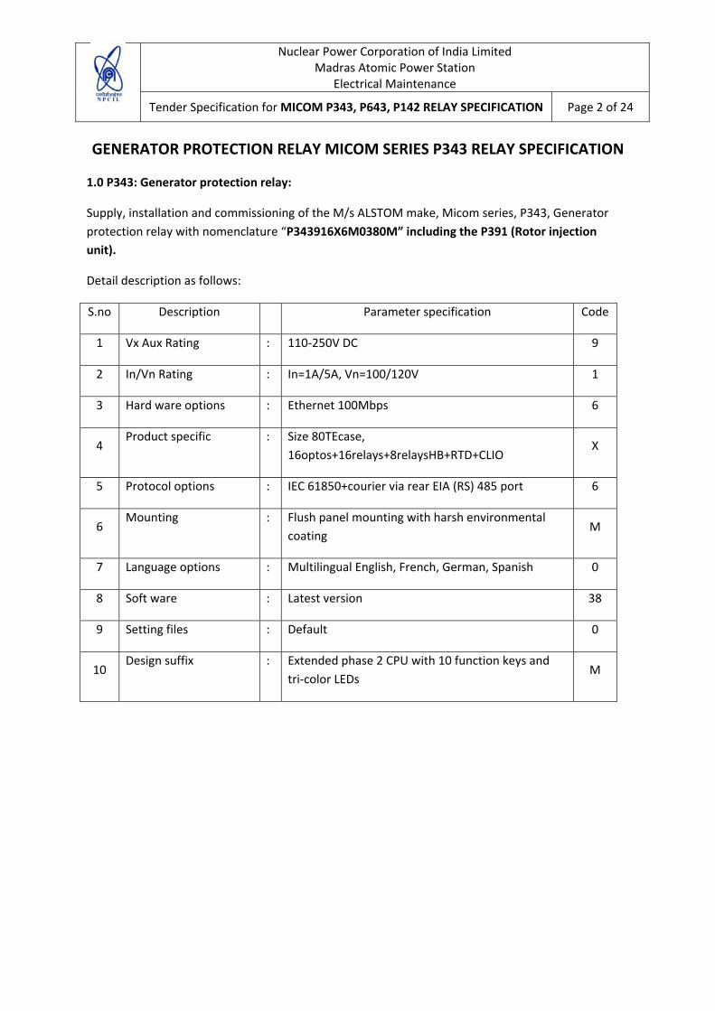
GENERATOR PROTECTION RELAY MICOM SERIES P343 RELAY SPECIFICATION
1.0 P343: Generator protection relay:
Supply, installation and commissioning of the M/s ALSTOM make, Micom series, P343, Generator protection relay with nomenclature “P343916X6M0380M” including the P391 (Rotor injection unit).
Detail description as follows:
S.no Description Parameter specification Code
1 Vx Aux Rating : 110‐250V DC 9
2 In/Vn Rating : In=1A/5A, Vn=100/120V 1
3 Hard ware options : Ethernet 100Mbps 6
4 Product specific : Size 80TEcase,
16optos+16relays+8relaysHB+RTD+CLIO X
5 Protocol options : IEC 61850+courier via rear EIA (RS) 485 port 6
6 Mounting : Flush panel mounting with harsh environmental
coating M
7 Language options : Multilingual English, French, German, Spanish 0
8 Soft ware : Latest version 38
9 Setting files : Default 0
10 Design suffix : Extended phase 2 CPU with 10 function keys and
tri‐color LEDs M
Nuclear Power Corporation of India Limited Madras Atomic Power Station
Electrical Maintenance
Tender Specification for MICOM P343, P643, P142 RELAY SPECIFICATION Page 3 of 24
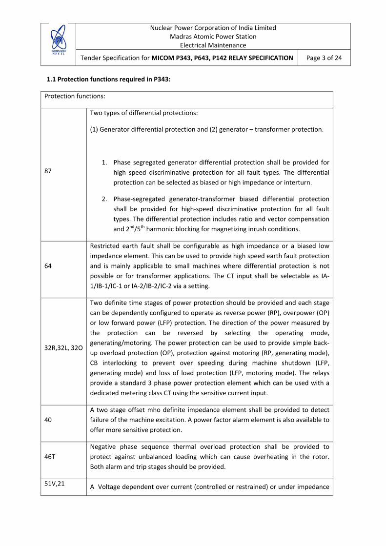
1.1 Protection functions required in P343:
Protection functions:
87
Two types of differential protections:
(1) Generator differential protection and (2) generator – transformer protection.
1. Phase segregated generator differential protection shall be provided for high speed discriminative protection for all fault types. The differential protection can be selected as biased or high impedance or interturn.
2. Phase‐segregated generator‐transformer biased differential protection shall be provided for high‐speed discriminative protection for all fault types. The differential protection includes ratio and vector compensation and 2nd/5th harmonic blocking for magnetizing inrush conditions.
64
Restricted earth fault shall be configurable as high impedance or a biased low impedance element. This can be used to provide high speed earth fault protection and is mainly applicable to small machines where differential protection is not possible or for transformer applications. The CT input shall be selectable as IA‐1/IB‐1/IC‐1 or IA‐2/IB‐2/IC‐2 via a setting.
32R,32L, 32O
Two definite time stages of power protection should be provided and each stage can be dependently configured to operate as reverse power (RP), overpower (OP) or low forward power (LFP) protection. The direction of the power measured by the protection can be reversed by selecting the operating mode, generating/motoring. The power protection can be used to provide simple back‐up overload protection (OP), protection against motoring (RP, generating mode), CB interlocking to prevent over speeding during machine shutdown (LFP, generating mode) and loss of load protection (LFP, motoring mode). The relays provide a standard 3 phase power protection element which can be used with a dedicated metering class CT using the sensitive current input.
40 A two stage offset mho definite impedance element shall be provided to detect failure of the machine excitation. A power factor alarm element is also available to offer more sensitive protection.
46T Negative phase sequence thermal overload protection shall be provided to protect against unbalanced loading which can cause overheating in the rotor. Both alarm and trip stages should be provided.
51V,21 A Voltage dependent over current (controlled or restrained) or under impedance
Nuclear Power Corporation of India Limited Madras Atomic Power Station
Electrical Maintenance
Tender Specification for MICOM P343, P643, P142 RELAY SPECIFICATION Page 4 of 24
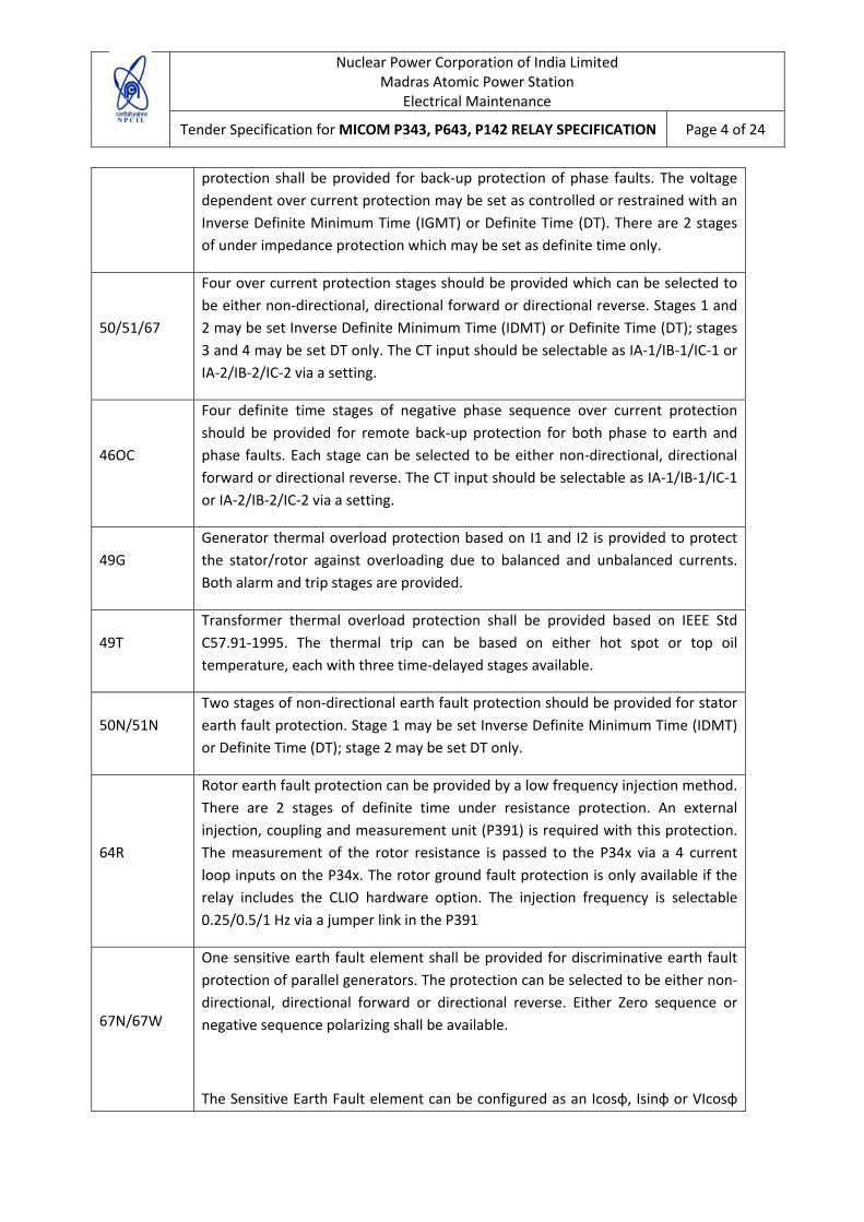
protection shall be provided for back‐up protection of phase faults. The voltage dependent over current protection may be set as controlled or restrained with an Inverse Definite Minimum Time (IGMT) or Definite Time (DT). There are 2 stages of under impedance protection which may be set as definite time only.
50/51/67
Four over current protection stages should be provided which can be selected to be either non‐directional, directional forward or directional reverse. Stages 1 and 2 may be set Inverse Definite Minimum Time (IDMT) or Definite Time (DT); stages 3 and 4 may be set DT only. The CT input should be selectable as IA‐1/IB‐1/IC‐1 or IA‐2/IB‐2/IC‐2 via a setting.
46OC
Four definite time stages of negative phase sequence over current protection should be provided for remote back‐up protection for both phase to earth and phase faults. Each stage can be selected to be either non‐directional, directional forward or directional reverse. The CT input should be selectable as IA‐1/IB‐1/IC‐1 or IA‐2/IB‐2/IC‐2 via a setting.
49G Generator thermal overload protection based on I1 and I2 is provided to protect the stator/rotor against overloading due to balanced and unbalanced currents. Both alarm and trip stages are provided.
49T Transformer thermal overload protection shall be provided based on IEEE Std C57.91‐1995. The thermal trip can be based on either hot spot or top oil temperature, each with three time‐delayed stages available.
50N/51N Two stages of non‐directional earth fault protection should be provided for stator earth fault protection. Stage 1 may be set Inverse Definite Minimum Time (IDMT) or Definite Time (DT); stage 2 may be set DT only.
64R
Rotor earth fault protection can be provided by a low frequency injection method. There are 2 stages of definite time under resistance protection. An external injection, coupling and measurement unit (P391) is required with this protection. The measurement of the rotor resistance is passed to the P34x via a 4 current loop inputs on the P34x. The rotor ground fault protection is only available if the relay includes the CLIO hardware option. The injection frequency is selectable 0.25/0.5/1 Hz via a jumper link in the P391
67N/67W
One sensitive earth fault element shall be provided for discriminative earth fault protection of parallel generators. The protection can be selected to be either non‐directional, directional forward or directional reverse. Either Zero sequence or negative sequence polarizing shall be available.
The Sensitive Earth Fault element can be configured as an Icosφ, Isinφ or VIcosφ

Nuclear Power Corporation of India Limited Madras Atomic Power Station
Electrical Maintenance
Tender Specification for MICOM P343, P643, P142 RELAY SPECIFICATION Page 5 of 24
(Watt metric) element for applicable to isolated and compensated networks.
59N
Residual over voltage protection shall be available for stator earth fault protection where there is an isolated or high impedance earth. The residual voltage can be measured from a broken delta VT, from the secondary winding of a distribution transformer earth at the generator neutral, or can be calculated from the three phase to neutral voltage measurements. Two independent stages of protection are provided for each measured neutral voltage input and also for the calculated value, each stage can be selected as either IDMT or DT. The P343 should have 2 measured and 2 calculated stages of residual over voltage protection.
27TN/59TN
A 3rd harmonic voltage element shall be provided to detect earth fault close to the generator star point. This element combined with the standard stator earth fault protection (59N/50N/51N) provides 100% stator earth fault protection.
A definite time 3rd harmonic under voltage element shall be provided if neutral voltage measurement is available at the neutral of the machine. This element is supervised by a 3 phase under voltage element and optionally by 3 phase W/VA/VAr elements. A 3rd harmonic over voltage element is provided if neutral voltage measurement is available from the terminals of the machine.
24
A five stage over fluxing (V/Hz) element shall be provided to protect the generator, or connect transformer, against over excitation. The first stage is a definite time alarm, the second stage can be used to provide an inverse or definite time trip characteristics and stages3/4/5 are definite time.
81R A 4‐stage rate of change of frequency element (df/dt) is provided for loss of Mains/Grid and load shedding applications.
50/27
A voltage supervised over current scheme is provided for dead machine/generator unintentional energisation at standstill (GUESS) protection to detect if the machine circuit breaker is closed accidentally, when the machine is not running. The CT input should be selectable as IA‐1/IB‐1/IC‐1 or IA‐2/IB‐2/IC‐2 via a setting.
27 A 2 stage under voltage protection element, configurable as either phase or phase to neutral measuring shall be provided to back up the automatic voltage regulator. Stage 1 may be selected as either IDMT or DT and stage 2 is DT only.
59 A 2 stage over voltage protection element, configurable as either phase to phase or phase to neutral measuring shall be provided to back up the automatic voltage regulator. Stage 1 may be selected as either IDMT or DT and stage 2 is DT only.

Nuclear Power Corporation of India Limited Madras Atomic Power Station
Electrical Maintenance
Tender Specification for MICOM P343, P643, P142 RELAY SPECIFICATION Page 6 of 24
47 A definite time negative phase sequence over voltage protection element shall be provided for either a tripping or interlocking function upon detection of unbalanced supply voltages.
81U/O A 4 stage definite time under frequency and 2 stage definite times over frequency protection is provided for load shedding and back‐up protection of the speed control governor.
81AB
Turbine abnormal frequency protection shall be provided to protect the turbine blade from potential damage due to prolonged under/over frequency operation of the generator. Up to six frequency bands can be programmed, each having an integrating timer to record the time spent within the band
RTD 10 RTDs (PT100) should be provided to monitor the temperature accurately in windings and bearings of the machine. Each RTD has an instantaneous alarm and definite time trip stage
50BF A 2‐stage circuit breaker failure function shall be provided with a 3 pole initiation input from external protection
37P/37N Phase, neutral and sensitive earth fault undercurrent elements should be available for use with for example the circuit breaker fail function
78
A lens shaped impedance characteristic shall be used to detect loss of synchronization (pole slipping) between the generation and the power system. Two zones are created by a reactance line which is used to distinguish whether the impedance centre of the pole slip is located in the power system or in the generator. Separate counters are used to count pole slips in the 2 zones. A setting shall also provided to determine whether the protection operates in a generating mode, motoring mode or both
BOL Blocked over current logic shall available on each stage of the over current, earth fault and sensitive earth fault protection. This consists of start outputs and block inputs that can be used to implement bus bar blocking schemes for example
VTS Voltage transformer supervision shall be provided (1,2,& 3 phase fuse failure detection) to prevent mal‐operation of voltage dependant protection elements on loss of a VT input signal
CTS Current transformer supervision shall be provided to prevent mal‐operation of current dependent protection elements upon loss of A CT input signal

Nuclear Power Corporation of India Limited Madras Atomic Power Station
Electrical Maintenance
Tender Specification for MICOM P343, P643, P142 RELAY SPECIFICATION Page 7 of 24
CLIO
4 analog (or current loop) inputs should be provided for transducers (vibration, tachometers etc.). Each input should have a definite time trip and alarm stage and each input can be set to operate for “Over” or ‘Under’ operation. Each input can be independently selected as 0‐1/0‐10/0‐20/4‐20 mA.
4 analogue (or current loop) outputs should be provided for the analogue measurements in the relay. Each output can be independently selected as 1/0‐10/0‐20/4‐20 mA
25
Check synchronizing (2 stage) with advanced system split features and breaker closing compensation time shall be provided. The P345 includes a dedicated voltage input for check synchronizing. For the P344 the VN2 input can be used for neutral voltage protection or check synchronizing. For the P342/3 the VN1 input can be used for neutral voltage protection or check synchronizing
Phase rotation – the rotation of the phases ABC or ACB for all 3 phase current and voltage channels can be selected. Also for pumped storage applications where 2‐phases are swapped the swapping of 2 phases can be emulated independently for the 3 phase voltage and 3 phase current channels
1.2 Functional Requirements:
The P343 shall support the following relay management functions in addition to the functions shown above.
• Measurement of all instantaneous & integrated values
• Circuit breaker control, status & condition monitoring
• Trip circuit and coil supervision
• 4 alternative setting groups
• Programmable function keys
• Control inputs
• Programmable scheme logic
• Programmable allocation of digital inputs and outputs
• Sequence of event recording
Nuclear Power Corporation of India Limited Madras Atomic Power Station
Electrical Maintenance
Tender Specification for MICOM P343, P643, P142 RELAY SPECIFICATION Page 8 of 24
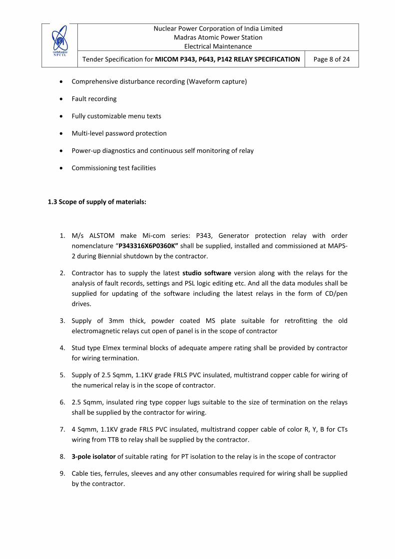
• Comprehensive disturbance recording (Waveform capture)
• Fault recording
• Fully customizable menu texts
• Multi‐level password protection
• Power‐up diagnostics and continuous self monitoring of relay
• Commissioning test facilities
1.3 Scope of supply of materials:
1. M/s ALSTOM make Mi‐com series: P343, Generator protection relay with order nomenclature “P343316X6P0360K” shall be supplied, installed and commissioned at MAPS‐2 during Biennial shutdown by the contractor.
2. Contractor has to supply the latest studio software version along with the relays for the analysis of fault records, settings and PSL logic editing etc. And all the data modules shall be supplied for updating of the software including the latest relays in the form of CD/pen drives.
3. Supply of 3mm thick, powder coated MS plate suitable for retrofitting the old electromagnetic relays cut open of panel is in the scope of contractor
4. Stud type Elmex terminal blocks of adequate ampere rating shall be provided by contractor for wiring termination.
5. Supply of 2.5 Sqmm, 1.1KV grade FRLS PVC insulated, multistrand copper cable for wiring of the numerical relay is in the scope of contractor.
6. 2.5 Sqmm, insulated ring type copper lugs suitable to the size of termination on the relays shall be supplied by the contractor for wiring.
7. 4 Sqmm, 1.1KV grade FRLS PVC insulated, multistrand copper cable of color R, Y, B for CTs wiring from TTB to relay shall be supplied by the contractor.
8. 3‐pole isolator of suitable rating for PT isolation to the relay is in the scope of contractor
9. Cable ties, ferrules, sleeves and any other consumables required for wiring shall be supplied by the contractor.

Nuclear Power Corporation of India Limited Madras Atomic Power Station
Electrical Maintenance
Tender Specification for MICOM P343, P643, P142 RELAY SPECIFICATION Page 9 of 24
10. DC Auxiliary supply at MAPS is 258‐260V DC, Hence this supply has to be regulated to 220V
DC for relay Aux supply and optos through electronic regulator or resistor. Suitable regulator/resistor has to be supplied by the contractor and same shall be wired for supply. Independent resistor / regulator are preferable for all Opto’s and Main power up circuit.
11. Ethernet cable of 20mtr length and 16 ports D‐link hub for rear port communication shall be supplied by the contractor.
1.4 Scope of service:
1. All tools & tackles and manpower shall be arranged by the contractor for the entire job.
2. Two P343 relays will be installed and commissioned and remaining one P343 relay will be spare for the installed relays.
3. Noting the existing wiring and Removal of the old electromagnetic relays as per FCN drawing issued by department and cutting the panel for retrofitting new plate suitable for mounting of numerical relays is in the scope of contractor.
4. Dummy sheet shall be provided for the cut open of all the relays which were removed/ deleted from the panel with the introduction of numerical relays.
5. Installing of new relay, and wiring to the relay as per the FCN drawing issued by department is in the scope of contractor.
6. All input and output terminals shall be brought to the independent Terminal Block, for the external wiring. Spare input and outputs shall be identified with spare sleeves for future use.
7. Power up of the relay, configuring and loading/editing the settings and PSL logics as per FCN issued by department is in the scope of contractor. Calibration of relays and functional checks has to be performed by the contractor.
8. Handing over the removed electromagnetic relays and scrapping the removed wiring and house keeping is in the scope of contractor.
9. The rear port communication of the relays shall be established to the local computer network through Ethernet by the contractor. A hub shall be provided centrally at protection panel and from hub Ethernet cable shall be laid to the computer station. All the mounted relays shall be connected to the hub through Ethernet.
Nuclear Power Corporation of India Limited Madras Atomic Power Station
Electrical Maintenance
Tender Specification for MICOM P343, P643, P142 RELAY SPECIFICATION Page 10 of 24
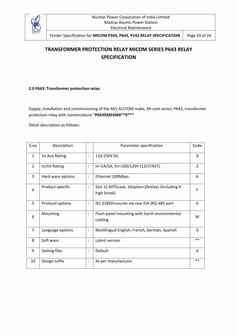
TRANSFORMER PROTECTION RELAY MICOM SERIES P643 RELAY SPECIFICATION
2.0 P643: Transformer protection relay:
Supply, installation and commissioning of the M/s ALSTOM make, Mi‐com series, P643, transformer protection relay with nomenclature “P643926F6M0**0**”
Detail description as follows:
S.no Description Parameter specification Code
1 Vx Aux Rating : 110‐250V DC 9
2 In/Vn Rating : In=1A/5A, Vn=100/120V (12CT/4VT) 2
3 Hard ware options : Ethernet 100Mbps 6
4 Product specific : Size 12 60TEcase, 16optos+20relays (Including 4
high break) F
5 Protocol options : IEC 61850+courier via rear EIA (RS) 485 port 6
6 Mounting : Flush panel mounting with harsh environmental
coating M
7 Language options : Multilingual English, French, German, Spanish 0
8 Soft ware : Latest version **
9 Setting files : Default 0
10 Design suffix : As per manufacturer **
Nuclear Power Corporation of India Limited Madras Atomic Power Station
Electrical Maintenance
Tender Specification for MICOM P343, P643, P142 RELAY SPECIFICATION Page 11 of 24
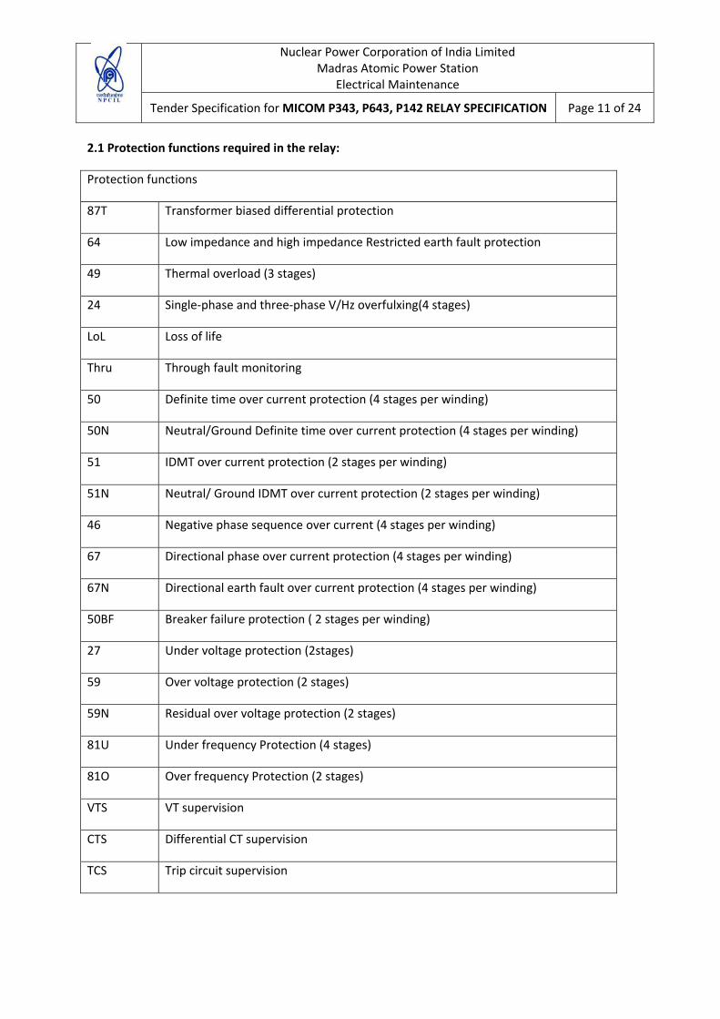
2.1 Protection functions required in the relay:
Protection functions
87T Transformer biased differential protection
64 Low impedance and high impedance Restricted earth fault protection
49 Thermal overload (3 stages)
24 Single‐phase and three‐phase V/Hz overfulxing(4 stages)
LoL Loss of life
Thru Through fault monitoring
50 Definite time over current protection (4 stages per winding)
50N Neutral/Ground Definite time over current protection (4 stages per winding)
51 IDMT over current protection (2 stages per winding)
51N Neutral/ Ground IDMT over current protection (2 stages per winding)
46 Negative phase sequence over current (4 stages per winding)
67 Directional phase over current protection (4 stages per winding)
67N Directional earth fault over current protection (4 stages per winding)
50BF Breaker failure protection ( 2 stages per winding)
27 Under voltage protection (2stages)
59 Over voltage protection (2 stages)
59N Residual over voltage protection (2 stages)
81U Under frequency Protection (4 stages)
81O Over frequency Protection (2 stages)
VTS VT supervision
CTS Differential CT supervision
TCS Trip circuit supervision
Nuclear Power Corporation of India Limited Madras Atomic Power Station
Electrical Maintenance
Tender Specification for MICOM P343, P643, P142 RELAY SPECIFICATION Page 12 of 24
2.2 Functional Requirements:
The P643 shall support the following relay management functions in addition to the functions shown above.
• Measurement of all instantaneous & integrated values
• Trip circuit supervision
• 4 alternative setting groups
• Programmable function keys
• Control inputs
• Programmable scheme logic
• Programmable allocation of digital inputs and outputs
• Sequence of event recording
• Comprehensive disturbance recording (Waveform capture)
• Fault recording
• Fully customizable menu texts
• Multi‐level password protection
• Power‐up diagnostics and continuous self monitoring of relay
• Commissioning test facilities
2.3 Scope of supply of materials:
1. M/s ALSTOM make Mi‐com series: P643, Transformer protection relay with order nomenclature “P643926F6M0**0**” shall be supplied, installed and commissioned at MAPS‐2 during Biennial shutdown by the contractor.
2. Contractor has to supply the latest studio software version along with the relays for the analysis of fault records, settings and PSL logic editing etc. And all the data modules shall be supplied for updating of the software including the latest relays in the form of CD/pen drives.

Nuclear Power Corporation of India Limited Madras Atomic Power Station
Electrical Maintenance
Tender Specification for MICOM P343, P643, P142 RELAY SPECIFICATION Page 13 of 24
3. Supply of 3mm thick, powder coated MS plate suitable for retrofitting the old
electromagnetic relays cut open of panel is in the scope of contractor
4. Stud type Elmex terminal blocks of adequate ampere rating shall be provided by contractor for wiring termination.
5. Supply of 2.5 Sqmm, 1.1KV grade FRLS PVC insulated, multistrand copper cable for wiring of the numerical relay is in the scope of contractor.
6. 2.5 Sqmm, insulated ring type copper lugs suitable to the size of termination on the relays shall be supplied by the contractor for wiring.
7. 4 Sqmm, 1.1KV grade FRLS PVC insulated, multistranded copper cable of color R, Y, B for CTs wiring from TTB to relay shall be supplied by the contractor.
8. 3‐pole isolator of suitable rating for PT isolation to the relay is in the scope of contractor
9. Cable ties, ferrules, sleeves and any other consumables required for wiring shall be supplied by the contractor.
10. DC Auxiliary supply at MAPS is 258‐260V DC, Hence this supply has to be regulated to 220V DC for relay Aux supply and optos through electronic regulator or resistor. Suitable regulator/resistor has to be supplied by the contractor and same shall be wired for supply. Independent resistor / regulator are preferable for all Opto’s and Main power up circuit.
11. Ethernet cable of 20mtr length and 16 ports D‐link hub for rear port communication shall be supplied by the contractor.
2.4 Scope of service:
1. All tools & tackles and manpower shall be arranged by the contractor for the entire job.
2. Three P643 relays will be installed and commissioned and remaining two P643 relays will be spare for the installed relays.
3. Noting the existing wiring and Removal of the old electromagnetic relays as per FCN drawing issued by department and cutting the panel for retrofitting new plate suitable for mounting of numerical relays is in the scope of contractor.
4. Dummy sheet shall be provided for the cut open of all the relays which were removed/ deleted from the panel with the introduction of numerical relays.
5. Installing of new relay, and wiring to the relay as per the FCN drawing issued by department is in the scope of contractor.
Nuclear Power Corporation of India Limited Madras Atomic Power Station
Electrical Maintenance
Tender Specification for MICOM P343, P643, P142 RELAY SPECIFICATION Page 14 of 24
6. All input and output terminals shall be brought to the independent Terminal Block, for the
external wiring. Spare input and outputs shall be identified with spare sleeves for future use.
7. Power up of the relay, configuring and loading/editing the settings and PSL logics as per FCN issued by department is in the scope of contractor. Calibration of relays and functional checks has to be performed by the contractor.
8. Handing over the removed electromagnetic relays and scrapping the removed wiring and housekeeping is in the scope of contractor.
9. The rear port communication of the relays shall be established to the local computer network through Ethernet by the contractor. A hub shall be provided centrally at protection panel and from hub Ethernet cable shall be laid to the computer station. All the mounted relays shall be connected to the hub through Ethernet.

Nuclear Power Corporation of India Limited Madras Atomic Power Station
Electrical Maintenance
Tender Specification for MICOM P343, P643, P142 RELAY SPECIFICATION Page 15 of 24
FEEDER MANAGEMENT RELAY, MICOM SERIES P142 RELAY SPECIFICATION
3.0 P142: Feeder management relay:
Supply, installation and commissioning of the M/s ALSTOM make, Mi‐com series, P142, Feeder management relay with nomenclature “P142916H6M0**0**”
Detail description as follows:
S.no Description Parameter specification Code
1 Vx Aux Rating : 110‐250V DC 9
2 In/Vn Rating : In=1A/5A, Vn=100/120V 1
3 Hard ware options : Ethernet 100Mbps 6
4 Product specific : 8optos+7relays+Additional 4 high break relays H
5 Protocol options : IEC 61850+courier via rear EIA (RS) 485 port 6
6 Mounting : Flush panel mounting with harsh environmental
coating M
7 Language options : Multilingual English, French, German, Spanish 0
8 Soft ware : Latest version **
9 Setting files : Default 0
10 Design suffix : As per manufacturer **
3.1 Protection functions required in P142 relay:
Protection functions:
50/51/67
Six over current measuring stages shall be available for each phase and are selectable to be either non‐directional, directional forward or directional reverse. Stages 1,2 and 5 may be set Inverse Definite Minimum Time (IDMT) or Definite Time (DT); stages 3, 4 and 6 may be set DT only
Nuclear Power Corporation of India Limited Madras Atomic Power Station
Electrical Maintenance
Tender Specification for MICOM P343, P643, P142 RELAY SPECIFICATION Page 16 of 24
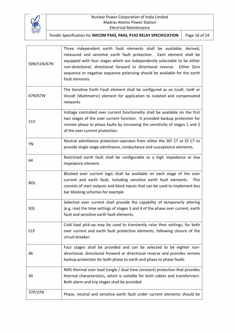
50N/51N/67N
Three independent earth fault elements shall be available; derived, measured and sensitive earth fault protection. Each element shall be equipped with four stages which are independently selectable to be either non‐directional, directional forward or directional reverse. Either Zero sequence or negative sequence polarizing should be available for the earth fault elements
67N/67W The Sensitive Earth Fault element shall be configured as an Icosθ, Isinθ or VIcosθ (Wattmetric) element for application to isolated and compensated networks
51V
Voltage controlled over current functionality shall be available on the first two stages of the over current function. It provided backup protection for remote phase to phase faults by increasing the sensitivity of stages 1 and 2 of the over current protection.
YN Neutral admittance protection‐operates from either the SEF CT or EF CT to provide single stage admittance, conductance and susceptance elements.
64 Restricted earth fault shall be configurable as a high impedance or low impedance element.
BOL
Blocked over current logic shall be available on each stage of the over current and earth fault, including sensitive earth fault elements. This consists of start outputs and block inputs that can be used to implement bus bar blocking schemes for example
SOL Selective over current shall provide the capability of temporarily altering (e.g. rise) the time settings of stages 3 and 4 of the phase over current, earth fault and sensitive earth fault elements.
CLP Cold load pick‐up may be used to transiently raise thee settings, for both over current and earth fault protection elements, following closure of the circuit breaker.
46 Four stages shall be provided and can be selected to be eighter non‐directional, directional forward or directional reverse and provides remote backup protection for both phase to earth and phase to phase faults
49 RMS thermal over load (single / dual time constant) protection that provides thermal characteristics, which is suitable for both cables and transformers. Both alarm and trip stages shall be provided
37P/37N Phase, neutral and sensitive earth fault under current elements should be
Nuclear Power Corporation of India Limited Madras Atomic Power Station
Electrical Maintenance
Tender Specification for MICOM P343, P643, P142 RELAY SPECIFICATION Page 17 of 24
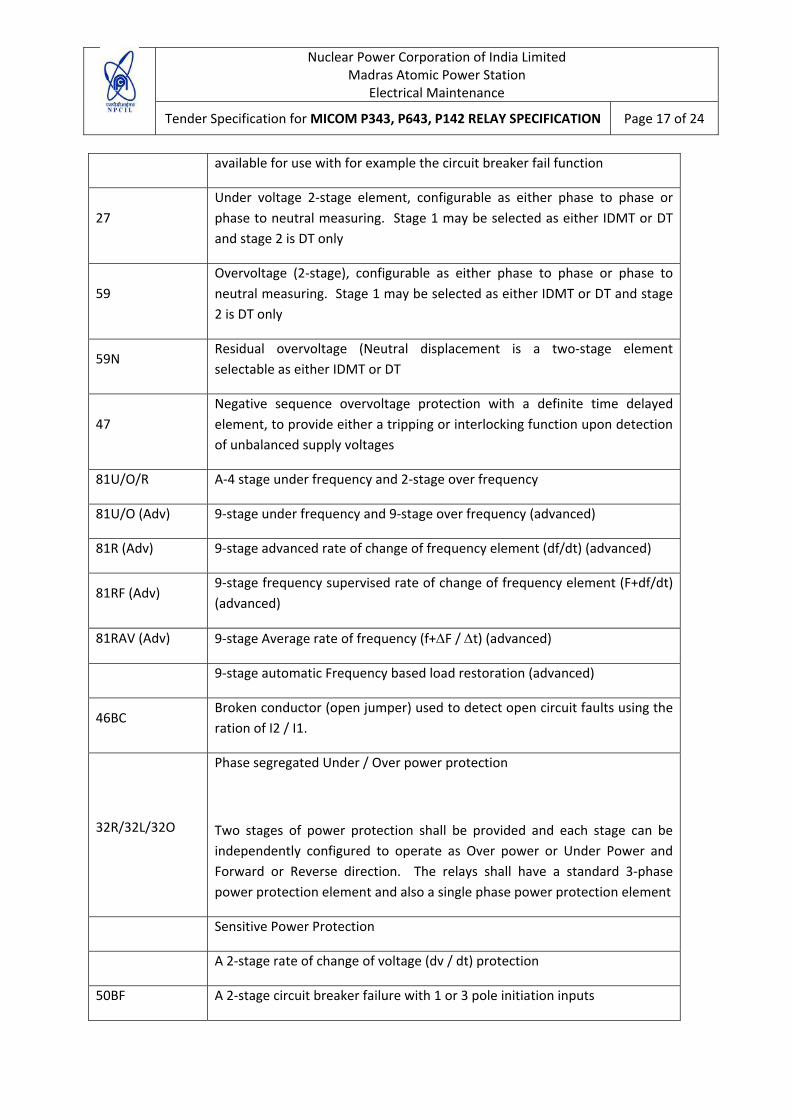
available for use with for example the circuit breaker fail function
27 Under voltage 2‐stage element, configurable as either phase to phase or phase to neutral measuring. Stage 1 may be selected as either IDMT or DT and stage 2 is DT only
59 Overvoltage (2‐stage), configurable as either phase to phase or phase to neutral measuring. Stage 1 may be selected as either IDMT or DT and stage 2 is DT only
59N Residual overvoltage (Neutral displacement is a two‐stage element selectable as either IDMT or DT
47 Negative sequence overvoltage protection with a definite time delayed element, to provide either a tripping or interlocking function upon detection of unbalanced supply voltages
81U/O/R A‐4 stage under frequency and 2‐stage over frequency
81U/O (Adv) 9‐stage under frequency and 9‐stage over frequency (advanced)
81R (Adv) 9‐stage advanced rate of change of frequency element (df/dt) (advanced)
81RF (Adv) 9‐stage frequency supervised rate of change of frequency element (F+df/dt) (advanced)
81RAV (Adv) 9‐stage Average rate of frequency (f+∆F / ∆t) (advanced)
9‐stage automatic Frequency based load restoration (advanced)
46BC Broken conductor (open jumper) used to detect open circuit faults using the ration of I2 / I1.
32R/32L/32O
Phase segregated Under / Over power protection
Two stages of power protection shall be provided and each stage can be independently configured to operate as Over power or Under Power and Forward or Reverse direction. The relays shall have a standard 3‐phase power protection element and also a single phase power protection element
Sensitive Power Protection
A 2‐stage rate of change of voltage (dv / dt) protection
50BF A 2‐stage circuit breaker failure with 1 or 3 pole initiation inputs

Nuclear Power Corporation of India Limited Madras Atomic Power Station
Electrical Maintenance
Tender Specification for MICOM P343, P643, P142 RELAY SPECIFICATION Page 18 of 24
VTS Voltage transformer supervision (1, 2 & 3 phase fuse failure detection) to prevent mal‐operation of voltage dependent protection elements upon loss of a VT input signal
CTS Current transformer supervision to prevent mal‐operation of current dependent protection elements upon loss of a CT input signal
49SR Silicon rectifier overload protection
79 4 shot three pole auto‐reclose with check sync., external initiation and sequence co‐ordination capability (P142/3/4/5 only)
25 Check synchronizing (2‐stage) with advanced system spilt features and breaker closing compensation time (P143 and P145 models only)
2nd Harmonic blocking
Programmable LED’s
3.2 Functional Requirements:
The P142 shall support the following relay management functions in addition to the functions shown above.
• Measurement of all instantaneous & integrated values
• Trip circuit and coil supervision
• 4 alternative setting groups
• Control inputs
• Programmable scheme logic
• Programmable allocation of digital inputs and outputs
• Sequence of event recording
• Comprehensive disturbance recording (Waveform capture)
• Fault recording
• Fully customizable menu texts
• Multi‐level password protection

Nuclear Power Corporation of India Limited Madras Atomic Power Station
Electrical Maintenance
Tender Specification for MICOM P343, P643, P142 RELAY SPECIFICATION Page 19 of 24
• Power‐up diagnostics and continuous self monitoring of relay
• Commissioning test facilities
3.3 Scope of supply of materials:
1. M/s ALSTOM make Mi‐com series: P142, Feeder management relay with order nomenclature “P142916H6M0**0**” shall be supplied, installed and commissioned at MAPS‐2 during Biennial shutdown by the contractor.
2. Contractor has to supply the latest studio software version along with the relays for the analysis of fault records, settings and PSL logic editing etc. And all the data modules shall be supplied for updating of the software including the latest relays in the form of CD/pen drives.
3. Supply of 3mm thick, powder coated MS plate suitable for retrofitting the old electromagnetic relays cut open of panel is in the scope of contractor
4. Stud type Elmex terminal blocks of adequate ampere rating shall be provided by contractor for wiring termination.
5. Supply of 2.5 Sqmm, 1.1KV grade FRLS PVC insulated, multistrand copper cable for wiring of the numerical relay is in the scope of contractor.
6. 2.5 Sqmm, insulated ring type copper lugs suitable to the size of termination on the relays shall be supplied by the contractor for wiring.
7. 4 Sqmm, 1.1KV grade FRLS PVC insulated, multistrand copper cable of color R, Y, B for CTs wiring from TTB to relay shall be supplied by the contractor.
8. 3‐pole isolator of suitable rating for PT isolation to the relay is in the scope of contractor
9. Cable ties, ferrules, sleeves and any other consumables required for wiring shall be supplied by the contractor.
10. DC Auxiliary supply at MAPS is 258‐260V DC, Hence this supply has to be regulated to 220V DC for relay Aux supply and optos through electronic regulator or resistor. Suitable regulator/resistor has to be supplied by the contractor and same shall be wired for supply. Independent resistor / regulator are preferable for all Opto’s and Main power up circuit.
11. Ethernet cable of 20mtr length and 16 ports D‐link hub for rear port communication shall be supplied by the contractor.
Nuclear Power Corporation of India Limited Madras Atomic Power Station
Electrical Maintenance
Tender Specification for MICOM P343, P643, P142 RELAY SPECIFICATION Page 20 of 24
3.4 Scope of service:
1. All tools & tackles and manpower shall be arranged by the contractor for the entire job.
2. Six P142 relays will be installed and commissioned and remaining two P142 relay will be spare for the installed relays.
3. Noting the existing wiring and Removal of the old electromagnetic relays as per FCN drawing issued by department and cutting the panel for retrofitting new plate suitable for mounting of numerical relays is in the scope of contractor.
4. Dummy sheet shall be provided for the cut open of all the relays which were removed/ deleted from the panel with the introduction of numerical relays.
5. Installing of new relay, and wiring to the relay as per the FCN drawing issued by department is in the scope of contractor.
6. All input and output terminals shall be brought to the independent Terminal Block, for the external wiring. Spare input and outputs shall be identified with spare sleeves for future use.
7. Power up of the relay, configuring and loading/editing the settings and PSL logics as per FCN issued by department is in the scope of contractor. Calibration of relays and functional checks has to be performed by the contractor.
8. Handing over the removed electromagnetic relays and scrapping the removed wiring and housekeeping is in the scope of contractor.
9. The rear port communication of the relays shall be established to the local computer network through Ethernet by the contractor. A hub shall be provided centrally at protection panel and from hub Ethernet cable shall be laid to the computer station. All the mounted relays shall be connected to the hub through Ethernet.
4.0 Documentation:
1. The technical guide, application manuals, operating manual, maintenance guide, commissioning guide and other documents pertaining to the relays shall be supplied in triplicate for both type of relays.
2. Software and data modules shall be supplied in the form of CDs / pen drive.
3. Retro fitting and commission report shall be submitted along with the drawings of wiring in triplicate.
Nuclear Power Corporation of India Limited Madras Atomic Power Station
Electrical Maintenance
Tender Specification for MICOM P343, P643, P142 RELAY SPECIFICATION Page 21 of 24
4.1 General scope:
1. Any deficiency raised shall be rectified by the contractor immediately.
2. Except the safety shoes all personal protective equipment will be issued by the department.
3. All persons working under this P.O shall follow the MAPS safety norms and no under aged (<18yrs) should work under this P.O.
4. One full day safety training has to be attended by all the employees on Wednesday of a week to get the pass for the entry of the MAPS premises.
5. Employees should possess any GOVT issued identity card with address proof and police verification certificate for getting pass more than 7days and up to 3months.
6. The site in‐charge should visit MAPS and arrange all the passes in ahead, before actual work starting. He should possess the photo copies of P.O, identity cards, PVC at least 5to 10nos and passport photographs (5 to 10nos) of employees for processing of pass formalities.
5.0 Type test certificates shall be submitted for the following tests
5.1 Insulation:
Per IEC 60255‐27:2005
Insulation resistance >100Mohm at 500VDC Using Electronic insulation tester.
5.2 Creepage distances and clearances:
IEC 60255‐27:2005
Pollution degree 3,
Overvoltage category III,
Impulse test voltage 5KV.
5.3 High voltage (Dielectric) withstand:
Nuclear Power Corporation of India Limited Madras Atomic Power Station
Electrical Maintenance
Tender Specification for MICOM P343, P643, P142 RELAY SPECIFICATION Page 22 of 24
I. Per IEC 60255‐27:2005, 2KV rms AC, 1minute between all independent circuits, between
independent circuits and protective (earth) conductor terminal. 1KV rms AC for 1 minute, across open watchdog contacts. 1KV rms AC for 1 minute, across open contacts of changeover output relays. 1KV rms AC for 1 minute for all D‐type EIA(RS)232/ EIA(RS)485 ports between the communications port terminals and protective (earth) conductor terminal.
II. Per ANSI/IEEE C37.90‐1989 (reaffirmed 1994): 1.5KV rms AC for 1 minute, across open contacts of normally open output relays. 1KV rms AC for 1minute, across open watch dog contacts. 1KV rms AC for 1 minute, across open contacts of changeover output relays
5.4 Impulse voltage withstand test:
Per IEC 60255‐27:2005
Front time: 1.2us, time to half value: 50us, peak value: 5KV, 0.5J between all independent circuits. Between all independent circuits and protective (earth) conductor terminal. Between the terminals of independent circuits EIA(RS)232 & EIA(RS)485 ports and normally open contacts of output relays excepted. IEC 60664‐1:2007 Impulse 9.6KV between injection resistor inputs and protective (case earth) conductor terminal.
6.0 Electromagnetic compatibility (EMC)
6.1 1MHz Burst high frequency disturbance test
Per IEC 60255‐22‐1:2005, Class III, Common‐mode test voltage: 2.5KV, differential test voltage: 1KV, test duration: 2S, Source impedance: 200ohm
6.2 100 kHz Damped oscillatory test
Per EN61000‐4‐18:2007: Level3, common mode test voltage: 2.5KV, Differential mode test voltage: 1KV
6.3 Electrical fast transient or burst requirements
Per IEC 60255‐22‐4:2002 and EN61000‐4‐4:2004. Test severity class III and IV: Amplitude: 2KV, burst frequency 5KHz (Class III), Amplitude: 4KV, burst frequency 2.5kHz (Class IV). Applied directly to

Nuclear Power Corporation of India Limited Madras Atomic Power Station
Electrical Maintenance
Tender Specification for MICOM P343, P643, P142 RELAY SPECIFICATION Page 23 of 24
auxiliary supply, and applied to all other inputs. (EIA(RS)232 ports excepted). Amplitude: 4KV, burst frequency 5 kHz (Class IV) applied directly to auxiliary.
6.4 Surge immunity test
(EIA(RS)232 ports excepted). Per EN 61000‐4‐5:2006 Level4, EN 60255‐22‐5:2002, time to half value: 1.2/50us, amplitude: 4KV between all groups and earth conductor terminal, amplitude: 2KV between terminals of each group. Level‐3: 1KV between terminals of injection resistor inputs
6.5 Immunity to radiated electromagnetic energy
Per IEC 60255‐22‐3:2007, Class III: (EN61000‐4‐3:2006, Level 3) test field strength, frequency band 80 to 1000MHz: 10V/m, test using AM: 1 kHz/80% am and am pulse modulated. Field strength of 35V/m.
6.6 Radiated immunity from digital communications
PerEN61000‐4‐3:2002, Level 4: test field strength, frequency band 800 to 960 MHz, and 1.4 to 2.0 GHz: 30 V/m, Test using AM: 1 kHz/80%.
6.7 Radiated immunity from digital radio telephones
Per IEC 61000‐4‐3:2002: 10V/m, 900 MHz and 1.89 GHz.
Immunity to conducted disturbances induced by radio frequency fields
Per IEC 61000‐4‐6:1996, Level3, Distributing test voltage: 10V.
6.8 Power frequency magnetic field immunity
Per IEC 61000‐4‐8:1994, Level 5, 100A/m applied continuously, 1000A/m applied for 3s. Per IEC 61000‐4‐9:1993, Level 5, 1000A/m applied in all planes. Per IEC 61000‐4‐10: 1993, Level 5, 100A/m applied in all planes at 100 KHz/1 MHz with a burst duration of 2s.
6.9 Conducted emissions
Per EN 55022:1998 Class A: 0.115‐0.5MHz, 79 dBuV (quasi peak) 66dBuV (average) 0.5‐3. MHz, 73dBuV (quasi peak) 60dBuV (average).
Nuclear Power Corporation of India Limited Madras Atomic Power Station
Electrical Maintenance
Tender Specification for MICOM P343, P643, P142 RELAY SPECIFICATION Page 24 of 24
6.10 Radiated Emissions
Per EN 55022: 1998 Class A: 30‐230 MHz, 40dBuV/m at 10m measurement distance, 230‐1GHz, 47dBuV/m at 10m measurement distance.
7.0 Routine test in the presence of inspection engineer from site:
1. IR value of output contacts
2. Visual inspection of relay
3. Injection of current and voltage and verifying the measurements.
4. Verification of programmable and non‐programmable LEDs and functional keys
5. Verification of all protection features including the PSL logics by simulating faults using injection kits
6. Verification of DRS(disturbance record system) and event logs through the ALSTOM studio software