or starter kit v2 - אור פתרונות אלקטרוניקה · · 2015-12-13or starter kit...
TRANSCRIPT

Or Electronics Solutions (2012) LTD. Website: www.Or-e.co.il Email: [email protected]
Page-1
Or Starter Kit V2.0
Arduino Uno Rev3 .................................................................................................... 5
Breadboard - Translucent Self-Adhesive (Clear) ................................................... 5
USB Cable A to B ..................................................................................................... 5
Ultrasonic Ranging Module HC-SR04 ..................................................................... 6
Prototype BreadBoard (Double-side) ..................................................................... 6
9V Battery Power Cable ........................................................................................... 6
Arduino Jumper Wires - 65pc's ............................................................................... 6
Flat Cable 40Pin - (F/F ,20cm).................................................................................. 7
Flat Cable 40Pin - (M/M ,20cm) ................................................................................ 7
Active Buzzer 2.048Khz ........................................................................................... 7
Passive Buzzer ......................................................................................................... 7
Experiment ................................................................................................ 8
Connection Table ........................................................................... 8
Sample Code ................................................................................. 8
Break Away Headers Straight ............................................................................... 10
Female Headers ..................................................................................................... 10
Relay Module - 2 Channels (5V) ............................................................................ 10
RGB Led Module (5050) ......................................................................................... 11
Experiment .............................................................................................. 11
Connection Table ......................................................................... 11
Sample Code ............................................................................... 11
PhotoResistor – Light Sensor ............................................................................... 13
Experiment .............................................................................................. 14
Connection Table1 ....................................................................... 14
Connection Table2 ....................................................................... 14
Sample Code ............................................................................... 14
Resistor 330 Ohm 1/4w .......................................................................................... 15
Resistor 1K Ohm 1/4w ........................................................................................... 15
Resistor 4.7K Ohm 1/4w ........................................................................................ 15

Or Electronics Solutions (2012) LTD. Website: www.Or-e.co.il Email: [email protected]
Page-2
Resistor 10K Ohm 1/4w ......................................................................................... 15
Ceramic Capacitor – 100nF ................................................................................... 16
Ceramic Capacitor – 10nF ..................................................................................... 16
Ceramic Capacitor – 1nF ....................................................................................... 16
Trimmer 1K Ohm (3296W) ..................................................................................... 17
Trimmer 10K Ohm (3296W) ................................................................................... 17
Trimmer 100K Ohm (3296W).................................................................................. 17
4-Digit 7-Segment Display (Common Cathode) ................................................... 18
Experiment .............................................................................................. 19
Connection Table ......................................................................... 19
Sample Code ............................................................................... 19
Led Matrix 8X8 - Red .............................................................................................. 24
Experiment .............................................................................................. 25
Connection Table1 ....................................................................... 25
Connection Table2 ....................................................................... 26
Connection Table3 ....................................................................... 26
Sample Code ............................................................................... 26
RF Transmitter Module – 433Mhz ......................................................................... 28
RF Receiver Module – 433Mhz .............................................................................. 28
Experiment .............................................................................................. 29
Transmitter Connection Table ...................................................... 29
Transmitter Code ......................................................................... 29
Receiver Connection Table .......................................................... 30
Receiver Code ............................................................................ 30
Serial Character LCD 16L2 Module (I2C) .............................................................. 31
I2C Addressing ............................................................................ 31
Connection Table ......................................................................... 32
Sample Code ............................................................................... 32
Arduino ProtoShield with mini Breadboard ......................................................... 34
Link To Schematic ....................................................................... 34
Arduino Sound Sensor Module ............................................................................. 35
Tilt Sensor .............................................................................................................. 36
Or Electronics Solutions (2012) LTD. Website: www.Or-e.co.il Email: [email protected]
Page-3
Experiment .............................................................................................. 37
Connection Table1 ....................................................................... 37
Connection Table2 ....................................................................... 37
Sample Code ............................................................................... 37
Infra-Red Remote Control ...................................................................................... 39
Infra-Red Receiver Diode ....................................................................................... 39
Infra-Red Led .......................................................................................................... 39
Infra-Red Receiver Diode - Datasheet ......................................... 39
Infra-Red Led ............................................................................... 39
Infra-Red Library Download ......................................................... 39
Experiment .............................................................................................. 40
Connection Table ......................................................................... 40
Sample Code ............................................................................... 40
Push Button 12X12 ................................................................................................ 42
Mini Push Button 6X6 ............................................................................................ 42
Experiment .............................................................................................. 43
Connection Table ......................................................................... 43
Sample Code ............................................................................... 43
Red Led – 5mm ...................................................................................................... 44
Green Led – 5mm .................................................................................................. 44
Blue Led – 5mm..................................................................................................... 44
Yellow Led – 5mm .................................................................................................. 44
White Led – 5mm.................................................................................................... 44
Experiment .............................................................................................. 45
Connection ................................................................................... 45
Sample Code ............................................................................... 45
Keypad 4x4 Matrix .................................................................................................. 46
Experiment .............................................................................................. 47
Connection Table ......................................................................... 47
Sample Code ............................................................................... 47
Rotary potentiometer 10k -Linear ......................................................................... 49
Experiment .............................................................................................. 49

Or Electronics Solutions (2012) LTD. Website: www.Or-e.co.il Email: [email protected]
Page-4
Connection Table ......................................................................... 49
Sample Code ............................................................................... 49
JoyStick Module ..................................................................................................... 50
Experiment .............................................................................................. 51
Connection Table ......................................................................... 51
Sample Code ............................................................................... 51
Micro Servo Module SG90 ..................................................................................... 52
Experiment .............................................................................................. 53
Connection Table ......................................................................... 53
Sample Code ............................................................................... 53
Stepper Motor 5V + ULN2003 Driver Module ........................................................ 54
Stepper Motor: ............................................................................. 54
Experiment .............................................................................................. 56
Connection Table ......................................................................... 56
Sample Code ............................................................................... 56
Transistor - NPN (2N3904) ..................................................................................... 57
Transistor - PNP (2N3906) ..................................................................................... 57
Temperature Sensor - TMP36 ................................................................................ 58
555 Timer ................................................................................................................ 58
Shift Register 8-Bit - SN74HC595 .......................................................................... 59
Experiment .............................................................................................. 60
Connection Table ......................................................................... 60
Connection Scheme ..................................................................... 60
Sample Code ............................................................................... 61
Diode Small Signal - 1N4148 ................................................................................. 61
Link To Product Page................................................................... 61
Screw Terminals 2.54mm Pitch (2-Pin) ................................................................. 62
Screw Terminals 2.54mm Pitch (3-Pin) ................................................................. 62
Screw Driver (2 In 1) ............................................................................................... 62

Or Electronics Solutions (2012) LTD. Website: www.Or-e.co.il Email: [email protected]
Page-5
Arduino Uno Rev3 Item
Arduino Main board "Arduino Uno Rev3" Link To Product Page
Description
Breadboard - Translucent Self-Adhesive (Clear) Item
Beyond the clear plastic, this is really just a regular, solderless breadboard. It has 2 power buses, 30 columns, and 10 rows - a total of 400 tie in points. All pins are spaced by a standard 0.1". The two sets of five rows are separated by about 0.3", perfect for straddling a DIP package over. The board accepts wire sizes in the range of 29-20AWG. This board also has a self-adhesive on the back. Link To Product Page
Description
USB Cable A to B Item
This is the most common A to B Male/Male type peripheral cable, the kind that’s usually used for printers. Compatible with : Arduino Uno, Mega, Duemilanove USB cable connection to the Computer Cable length: 150 cm
Description

Or Electronics Solutions (2012) LTD. Website: www.Or-e.co.il Email: [email protected]
Page-6
Ultrasonic Ranging Module HC-SR04 Item
Ultrasonic Range Sensor Link To Product Page
Description
Prototype BreadBoard (Double-side) Item
Double-Side Prototype Board. Holes are plated through Both sides are identical. Dimension: 60 X 80 (mm) Grid : 0.1" (2.54mm) Thickness : 1.6mm Hole diameter : 0.95mm Material : FR-4 (glass fiber)
Description
9V Battery Power Cable Item
Cable Connection for 9V Battery to the Arduino power plug.
Plug the 9 volt battery clip onto a standard 9V battery and connect the other end to anything with a 5.5x2.1mm, center-positive barrel jack.
Description
Arduino Jumper Wires - 65pc's Item
Breadboard jumper wire 65 pcs in pack (Male-Male).
Including 4 different length:
200mm,165mm,125mm,80mm
Perfect design for breadboard.
Description
Or Electronics Solutions (2012) LTD. Website: www.Or-e.co.il Email: [email protected]
Page-7
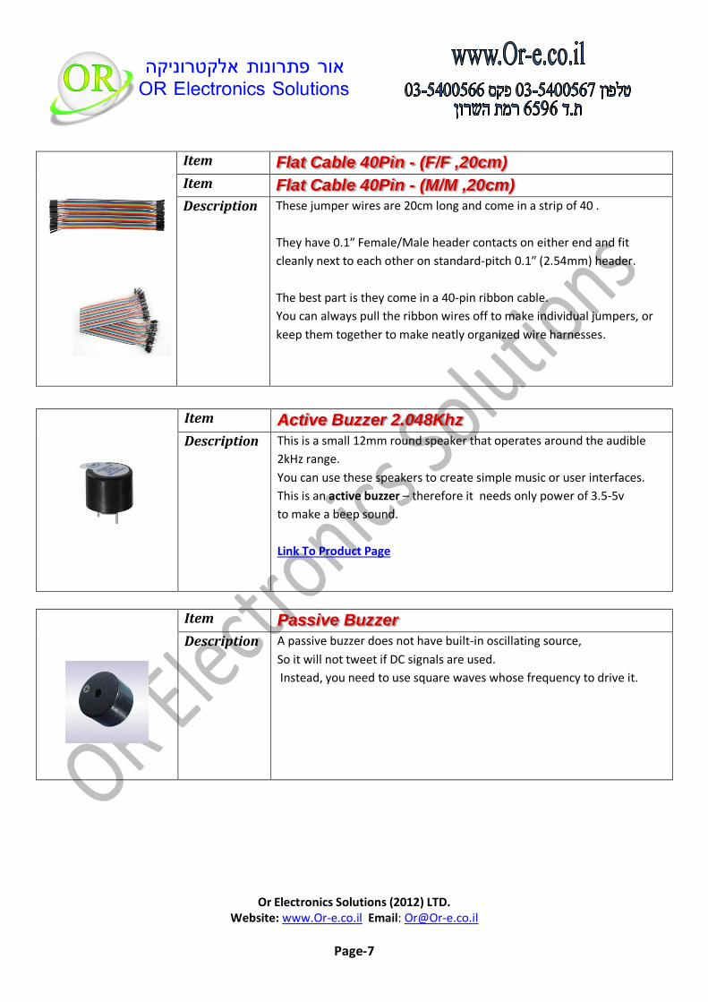
Flat Cable 40Pin - (F/F ,20cm) Item
Flat Cable 40Pin - (M/M ,20cm) Item
These jumper wires are 20cm long and come in a strip of 40 .
They have 0.1″ Female/Male header contacts on either end and fit
cleanly next to each other on standard-pitch 0.1″ (2.54mm) header.
The best part is they come in a 40-pin ribbon cable.
You can always pull the ribbon wires off to make individual jumpers, or
keep them together to make neatly organized wire harnesses.
Description
Active Buzzer 2.048Khz Item
This is a small 12mm round speaker that operates around the audible
2kHz range.
You can use these speakers to create simple music or user interfaces.
This is an active buzzer – therefore it needs only power of 3.5-5v
to make a beep sound.
Link To Product Page
Description
Passive Buzzer Item
A passive buzzer does not have built-in oscillating source,
So it will not tweet if DC signals are used.
Instead, you need to use square waves whose frequency to drive it.
Description

Or Electronics Solutions (2012) LTD. Website: www.Or-e.co.il Email: [email protected]
Page-8
Experiment
Connection Table
Active Buzzer Pin Arduino Pin
+ D6
- GND
Sample Code
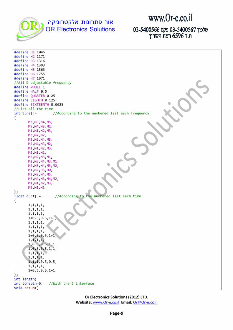
//Connect The (+) lead of Buzzer to D6 // and the (-) lead to GND #define D0 -1 #define D1 262 #define D2 293 #define D3 329 #define D4 349 #define D5 392 #define D6 440 #define D7 494 #define M1 523 #define M2 586 #define M3 658 #define M4 697 #define M5 783 #define M6 879 #define M7 987
Or Electronics Solutions (2012) LTD. Website: www.Or-e.co.il Email: [email protected]
Page-9
#define H1 1045 #define H2 1171 #define H3 1316 #define H4 1393 #define H5 1563 #define H6 1755 #define H7 1971 //All D adjustable frequency #define WHOLE 1 #define HALF 0.5 #define QUARTER 0.25 #define EIGHTH 0.125 #define SIXTEENTH 0.0625 //List all the time int tune[]= //According to the numbered list each frequency { M3,M3,M4,M5, M5,M4,M3,M2, M1,M1,M2,M3, M3,M2,M2, M3,M3,M4,M5, M5,M4,M3,M2, M1,M1,M2,M3, M2,M1,M1, M2,M2,M3,M1, M2,M3,M4,M3,M1, M2,M3,M4,M3,M2, M1,M2,D5,D0, M3,M3,M4,M5, M5,M4,M3,M4,M2, M1,M1,M2,M3, M2,M1,M1 }; float durt[]= //According to the numbered list each time { 1,1,1,1, 1,1,1,1, 1,1,1,1, 1+0.5,0.5,1+1, 1,1,1,1, 1,1,1,1, 1,1,1,1, 1+0.5,0.5,1+1, 1,1,1,1, 1,0.5,0.5,1,1, 1,0.5,0.5,1,1, 1,1,1,1, 1,1,1,1, 1,1,1,0.5,0.5, 1,1,1,1, 1+0.5,0.5,1+1, }; int length; int tonepin=6; //With the 6 interface void setup()

Or Electronics Solutions (2012) LTD. Website: www.Or-e.co.il Email: [email protected]
Page-10
{ pinMode(tonepin,OUTPUT); length=sizeof(tune)/sizeof(tune[0]); //Calculation of the length } void loop() { for(int x=0;x<length;x++) { tone(tonepin,tune[x]); delay(500*durt[x]); //Here according to beat delay, 500 of the index can make their own adjustments, in the music, I found 500 more appropriate. noTone(tonepin); } delay(2000); }
Break Away Headers Straight Item
Female Headers Item
A straight row of headers (Male and female ) break to fit.
40 pins that can be cut to any size.
Pin Style: Square
Number of Pins: 40
Pin Spacing: 0.1" (2.54 mm)
Break Away Headers Straight - Link To Product Page
Female Headers - Link To Product Page
Description
Relay Module - 2 Channels (5V) Item
Relay Module – 2 channels (Opto-isolated)
Link To Product Page
Description
Or Electronics Solutions (2012) LTD. Website: www.Or-e.co.il Email: [email protected]
Page-11
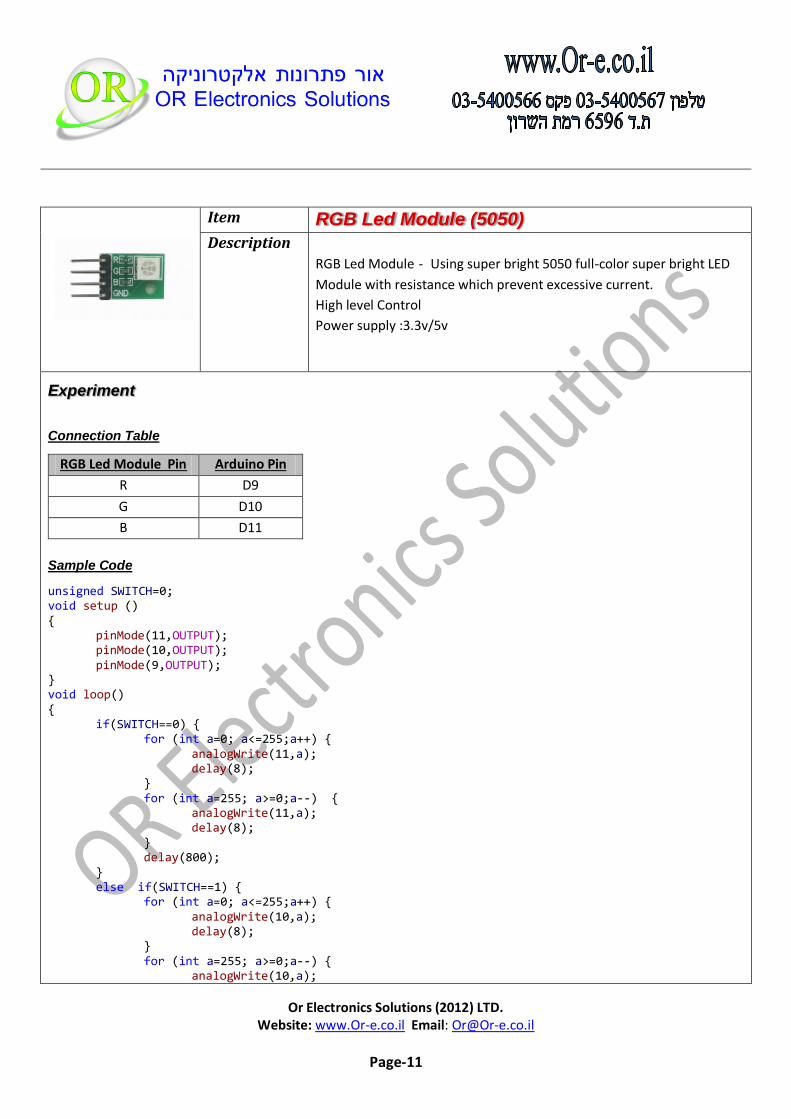
RGB Led Module (5050) Item
RGB Led Module - Using super bright 5050 full-color super bright LED
Module with resistance which prevent excessive current.
High level Control
Power supply :3.3v/5v
Description
Experiment
Connection Table
RGB Led Module Pin Arduino Pin
R D9
G D10
B D11
Sample Code
unsigned SWITCH=0; void setup () { pinMode(11,OUTPUT); pinMode(10,OUTPUT); pinMode(9,OUTPUT); } void loop() { if(SWITCH==0) { for (int a=0; a<=255;a++) { analogWrite(11,a); delay(8); } for (int a=255; a>=0;a--) { analogWrite(11,a); delay(8); } delay(800); } else if(SWITCH==1) { for (int a=0; a<=255;a++) { analogWrite(10,a); delay(8); } for (int a=255; a>=0;a--) { analogWrite(10,a);

Or Electronics Solutions (2012) LTD. Website: www.Or-e.co.il Email: [email protected]
Page-12
delay(8); } delay(800); } else if(SWITCH==2) { for (int a=0; a<=255;a++) { analogWrite(9,a); delay(8); } for (int a=255; a>=0;a--) { analogWrite(9,a); delay(8); } delay(800); } else if(SWITCH==3) { for (int a=0; a<=255;a++) { analogWrite(11,a); analogWrite(10,a); analogWrite(9,a); delay(8); } for (int a=255; a>=0;a--) { analogWrite(11,a); analogWrite(10,a); analogWrite(9,a); delay(8); } delay(800); } SWITCH++; if(SWITCH==4) SWITCH=0; }

Or Electronics Solutions (2012) LTD. Website: www.Or-e.co.il Email: [email protected]
Page-13
PhotoResistor – Light Sensor Item
A Photo Resistor changes its resistance depending on the amount
of light it is exposed to.
These little sensors make great ambient light triggers
(when light in the room turns on, do something).
Light resistance : ~15k Ohm
Dark resistance : ~1M Ohm
Max voltage : 150V
Max power: 100mW
Link To Product Page
Description

Or Electronics Solutions (2012) LTD. Website: www.Or-e.co.il Email: [email protected]
Page-14
Experiment
Connection Table1
Light Sensor Arduino Pin
Pin 1 A0
Pin 2 VCC
Connection Table2
Resistor 10K Arduino Pin
Pin 1 A0
Pin 2 GND
Sample Code
int LDR_Pin = A0; //analog pin 0 void setup(){ Serial.begin(9600); } void loop(){ int LDRReading = analogRead(LDR_Pin); Serial.println(LDRReading); delay(250); //just here to slow down the output for easier reading }
Or Electronics Solutions (2012) LTD. Website: www.Or-e.co.il Email: [email protected]
Page-15
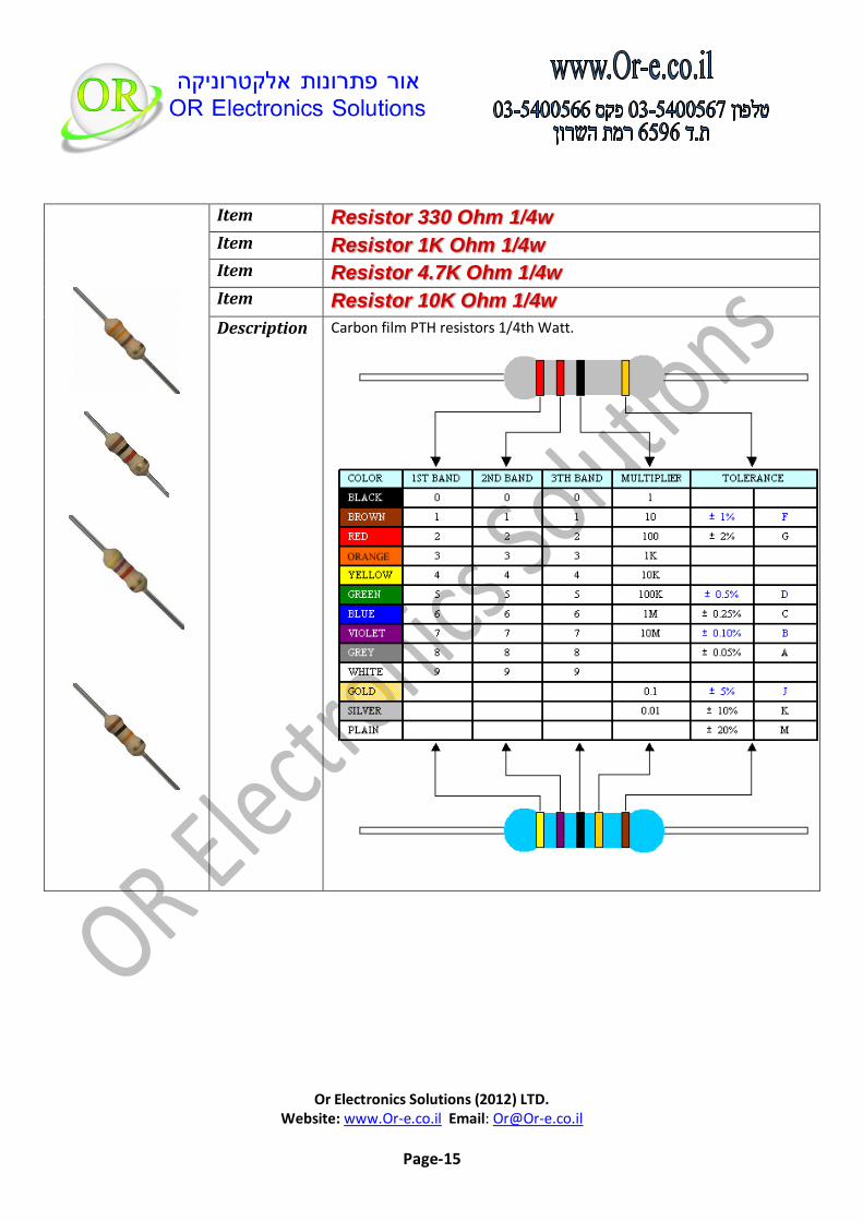
Resistor 330 Ohm 1/4w Item
Resistor 1K Ohm 1/4w Item
Resistor 4.7K Ohm 1/4w Item
Resistor 10K Ohm 1/4w Item
Carbon film PTH resistors 1/4th Watt. Description
Or Electronics Solutions (2012) LTD. Website: www.Or-e.co.il Email: [email protected]
Page-16
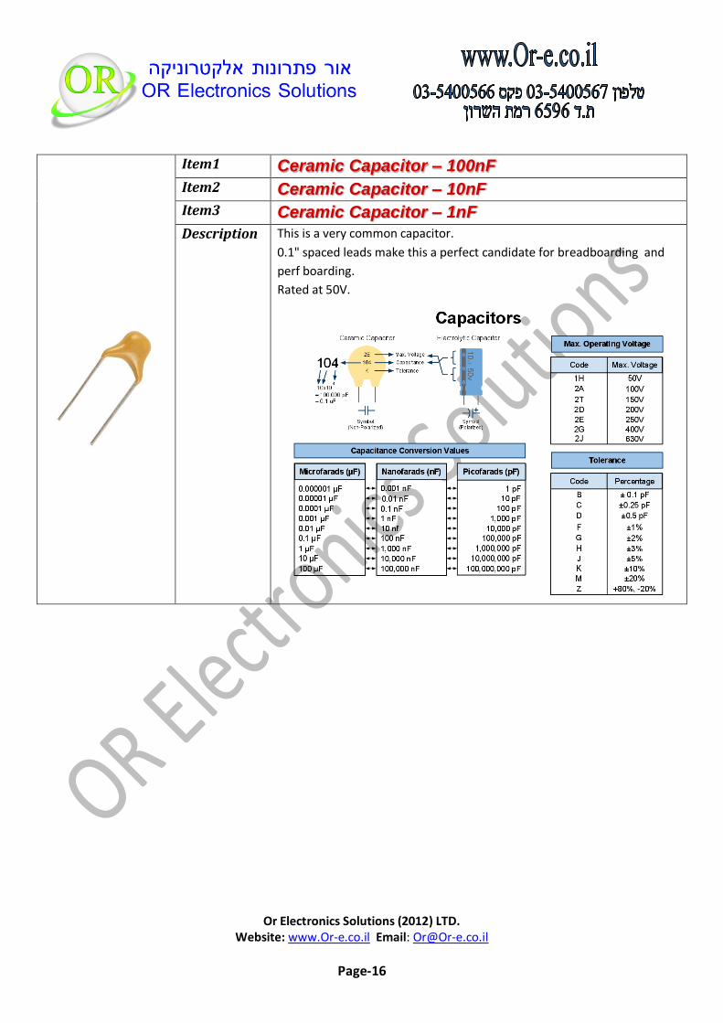
Ceramic Capacitor – 100nF Item1
Ceramic Capacitor – 10nF Item2
Ceramic Capacitor – 1nF Item3
This is a very common capacitor.
0.1" spaced leads make this a perfect candidate for breadboarding and
perf boarding.
Rated at 50V.
Description

Or Electronics Solutions (2012) LTD. Website: www.Or-e.co.il Email: [email protected]
Page-17
Trimmer 1K Ohm (3296W) Item1
Trimmer 10K Ohm (3296W) Item2
Trimmer 100K Ohm (3296W) Item3
These potentiometers are multi-turn which performs a variety of circuit
adjustments in all types of electronic equipment.
Typical applications are measuring linear distance, angle or rotation in
production equipment's.
Features:
25 turns and rotational life of 200 cycles
±10% tolerance
Power rating is 0.5W
Description

Or Electronics Solutions (2012) LTD. Website: www.Or-e.co.il Email: [email protected]
Page-18
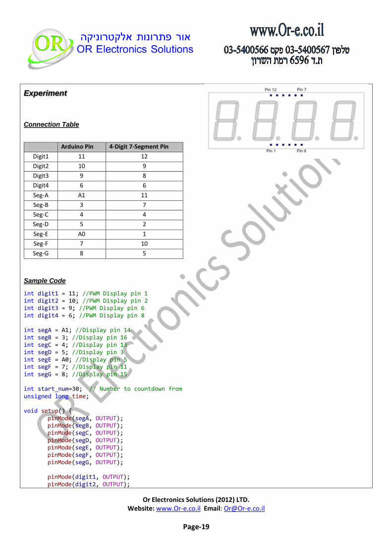
4-Digit 7-Segment Display (Common Cathode) Item
The 4-Digit 7-Segment Display is a self-contained module containing
four 7-segment LED numeric displays
Each segment in the display is multiplexed, meaning it shares the same
Cathode (common Cathode) connection points.
This reduces the wiring required when developing projects that need
multiple digit displays and allows each digit to be turned on or off
independently.
Description
Or Electronics Solutions (2012) LTD. Website: www.Or-e.co.il Email: [email protected]
Page-19
Experiment
Connection Table
Arduino Pin 4-Digit 7-Segment Pin
Digit1 11 12
Digit2 10 9
Digit3 9 8
Digit4 6 6
Seg-A A1 11
Seg-B 3 7
Seg-C 4 4
Seg-D 5 2
Seg-E A0 1
Seg-F 7 10
Seg-G 8 5
Sample Code
int digit1 = 11; //PWM Display pin 1 int digit2 = 10; //PWM Display pin 2 int digit3 = 9; //PWM Display pin 6 int digit4 = 6; //PWM Display pin 8 int segA = A1; //Display pin 14 int segB = 3; //Display pin 16 int segC = 4; //Display pin 13 int segD = 5; //Display pin 3 int segE = A0; //Display pin 5 int segF = 7; //Display pin 11 int segG = 8; //Display pin 15 int start_num=30; // Number to countdown from unsigned long time; void setup() { pinMode(segA, OUTPUT); pinMode(segB, OUTPUT); pinMode(segC, OUTPUT); pinMode(segD, OUTPUT); pinMode(segE, OUTPUT); pinMode(segF, OUTPUT); pinMode(segG, OUTPUT); pinMode(digit1, OUTPUT); pinMode(digit2, OUTPUT);

Or Electronics Solutions (2012) LTD. Website: www.Or-e.co.il Email: [email protected]
Page-20
pinMode(digit3, OUTPUT); pinMode(digit4, OUTPUT); pinMode(13, OUTPUT); // Onboard Led } void loop() { if((millis()/1000) < start_num){ displayNumber(start_num -(millis()/1000)); } else { // reached zero, flash the display time=millis(); while(millis() < time+200) { displayNumber(0); // display 0 for 0.2 second } time=millis(); while(millis() < time+200) { lightNumber(10); // Turn display off for 0.2 second } } } //Given a number, we display 10:22 //After running through the 4 numbers, the display is left turned off //Display brightness //Each digit is on for a certain amount of microseconds //Then it is off until we have reached a total of 20ms for the function call //Let's assume each digit is on for 1000us //If each digit is on for 1ms, there are 4 digits, so the display //is off for 16ms. //That's a ratio of 1ms to 16ms or 6.25% on time (PWM). //Let's define a variable called brightness that varies from: //5000 blindingly bright (15.7mA current draw per digit) //2000 shockingly bright (11.4mA current draw per digit) //1000 pretty bright (5.9mA) //500 normal (3mA) //200 dim but readable (1.4mA) //50 dim but readable (0.56mA) //5 dim but readable (0.31mA) //1 dim but readable in dark (0.28mA) void displayNumber(int toDisplay) { #define DISPLAY_BRIGHTNESS 500 #define DIGIT_ON LOW #define DIGIT_OFF HIGH long beginTime = millis(); for(int digit = 4 ; digit > 0 ; digit--) { //Turn on a digit for a short amount of time switch(digit) {

Or Electronics Solutions (2012) LTD. Website: www.Or-e.co.il Email: [email protected]
Page-21
case 1: digitalWrite(digit1, DIGIT_ON); break; case 2: digitalWrite(digit2, DIGIT_ON); break; case 3: digitalWrite(digit3, DIGIT_ON); break; case 4: digitalWrite(digit4, DIGIT_ON); break; } //Turn on the right segments for this digit lightNumber(toDisplay % 10); toDisplay /= 10; delayMicroseconds(DISPLAY_BRIGHTNESS); //Display digit for fraction of a second (1us to 5000us, 500 is pretty good) //Turn off all segments lightNumber(10); //Turn off all digits digitalWrite(digit1, DIGIT_OFF); digitalWrite(digit2, DIGIT_OFF); digitalWrite(digit3, DIGIT_OFF); digitalWrite(digit4, DIGIT_OFF); } while( (millis() - beginTime) < 10) ; //Wait for 20ms to pass before we paint the display again } //Given a number, turns on those segments //If number == 10, then turn off number void lightNumber(int numberToDisplay) { #define SEGMENT_ON HIGH #define SEGMENT_OFF LOW switch (numberToDisplay){ case 0: digitalWrite(segA, SEGMENT_ON); digitalWrite(segB, SEGMENT_ON); digitalWrite(segC, SEGMENT_ON); digitalWrite(segD, SEGMENT_ON); digitalWrite(segE, SEGMENT_ON); digitalWrite(segF, SEGMENT_ON); digitalWrite(segG, SEGMENT_OFF); break; case 1: digitalWrite(segA, SEGMENT_OFF); digitalWrite(segB, SEGMENT_ON); digitalWrite(segC, SEGMENT_ON); digitalWrite(segD, SEGMENT_OFF);

Or Electronics Solutions (2012) LTD. Website: www.Or-e.co.il Email: [email protected]
Page-22
digitalWrite(segE, SEGMENT_OFF); digitalWrite(segF, SEGMENT_OFF); digitalWrite(segG, SEGMENT_OFF); break; case 2: digitalWrite(segA, SEGMENT_ON); digitalWrite(segB, SEGMENT_ON); digitalWrite(segC, SEGMENT_OFF); digitalWrite(segD, SEGMENT_ON); digitalWrite(segE, SEGMENT_ON); digitalWrite(segF, SEGMENT_OFF); digitalWrite(segG, SEGMENT_ON); break; case 3: digitalWrite(segA, SEGMENT_ON); digitalWrite(segB, SEGMENT_ON); digitalWrite(segC, SEGMENT_ON); digitalWrite(segD, SEGMENT_ON); digitalWrite(segE, SEGMENT_OFF); digitalWrite(segF, SEGMENT_OFF); digitalWrite(segG, SEGMENT_ON); break; case 4: digitalWrite(segA, SEGMENT_OFF); digitalWrite(segB, SEGMENT_ON); digitalWrite(segC, SEGMENT_ON); digitalWrite(segD, SEGMENT_OFF); digitalWrite(segE, SEGMENT_OFF); digitalWrite(segF, SEGMENT_ON); digitalWrite(segG, SEGMENT_ON); break; case 5: digitalWrite(segA, SEGMENT_ON); digitalWrite(segB, SEGMENT_OFF); digitalWrite(segC, SEGMENT_ON); digitalWrite(segD, SEGMENT_ON); digitalWrite(segE, SEGMENT_OFF); digitalWrite(segF, SEGMENT_ON); digitalWrite(segG, SEGMENT_ON); break; case 6: digitalWrite(segA, SEGMENT_ON); digitalWrite(segB, SEGMENT_OFF); digitalWrite(segC, SEGMENT_ON); digitalWrite(segD, SEGMENT_ON); digitalWrite(segE, SEGMENT_ON); digitalWrite(segF, SEGMENT_ON); digitalWrite(segG, SEGMENT_ON); break;

Or Electronics Solutions (2012) LTD. Website: www.Or-e.co.il Email: [email protected]
Page-23
case 7: digitalWrite(segA, SEGMENT_ON); digitalWrite(segB, SEGMENT_ON); digitalWrite(segC, SEGMENT_ON); digitalWrite(segD, SEGMENT_OFF); digitalWrite(segE, SEGMENT_OFF); digitalWrite(segF, SEGMENT_OFF); digitalWrite(segG, SEGMENT_OFF); break; case 8: digitalWrite(segA, SEGMENT_ON); digitalWrite(segB, SEGMENT_ON); digitalWrite(segC, SEGMENT_ON); digitalWrite(segD, SEGMENT_ON); digitalWrite(segE, SEGMENT_ON); digitalWrite(segF, SEGMENT_ON); digitalWrite(segG, SEGMENT_ON); break; case 9: digitalWrite(segA, SEGMENT_ON); digitalWrite(segB, SEGMENT_ON); digitalWrite(segC, SEGMENT_ON); digitalWrite(segD, SEGMENT_ON); digitalWrite(segE, SEGMENT_OFF); digitalWrite(segF, SEGMENT_ON); digitalWrite(segG, SEGMENT_ON); break; case 10: digitalWrite(segA, SEGMENT_OFF); digitalWrite(segB, SEGMENT_OFF); digitalWrite(segC, SEGMENT_OFF); digitalWrite(segD, SEGMENT_OFF); digitalWrite(segE, SEGMENT_OFF); digitalWrite(segF, SEGMENT_OFF); digitalWrite(segG, SEGMENT_OFF); break; } }

Or Electronics Solutions (2012) LTD. Website: www.Or-e.co.il Email: [email protected]
Page-24
Led Matrix 8X8 - Red Item
Vf = 2.0 – 2.5 (v) If(Max) = 30mA
These can be very useful displays.
To control a matrix, you connect both its rows and columns to your microcontroller.
The columns are connected to the LEDs cathodes (see Figure 1), so a column needs to be high for any of the LEDs in that column to turn on.
The rows are connected to the LEDs anodes, so the row needs to be low for an individual LED to turn on. If the row and the column are both high or both low, no voltage flows through the LED and it doesn’t turn on.
To control an individual LED, you set its column high and its row low. To control multiple LEDs in a row, you set the rows high, then take the column high, then set the lows row or high as appropriate; a low row will turn the corresponding LED on, and a high row will turn it off.
Although there are pre-made LED matrices, you can also make your own matrix from 64 LEDs, using the schematic as shown above.
It doesn’t matter which pins of the microcontroller you connect the rows and columns to, because you can assign things in software. Connected the pins in a way that makes wiring easiest.
A typical layout is shown below.
Description

Or Electronics Solutions (2012) LTD. Website: www.Or-e.co.il Email: [email protected]
Page-25
Experiment
The 16 pins of the matrix are hooked up to 16 pins of the Arduino. Four of the analog pins are used as digital inputs 16 through 19. The order of the pins is assigned in two arrays in the code. Two potentiometers, connected to analog pins 0 and 1, control the movement of a lit LED In the matrix.
Connection Table1
Matrix Pin
Row Column Arduino
1 5 - 13
2 7 - 12
3 - 2 11 (see remark)
4 - 3 10 (see remark)
5 8 - 16(A2)
6 - 5 17(A3) (see remark)
7 6 - 18(A4)
8 3 - 19(A5)
9 1 - 2
10 - 4 3 (see remark)
11 - 6 4 (see remark)
12 4 - 5
13 - 1 6 (see remark)
14 2 - 7
15 - 7 8 (see remark)
16 - 8 9 (see remark)
(*) Connect it to the arduino Thru Serial Resistor 330Ohm
Or Electronics Solutions (2012) LTD. Website: www.Or-e.co.il Email: [email protected]
Page-26
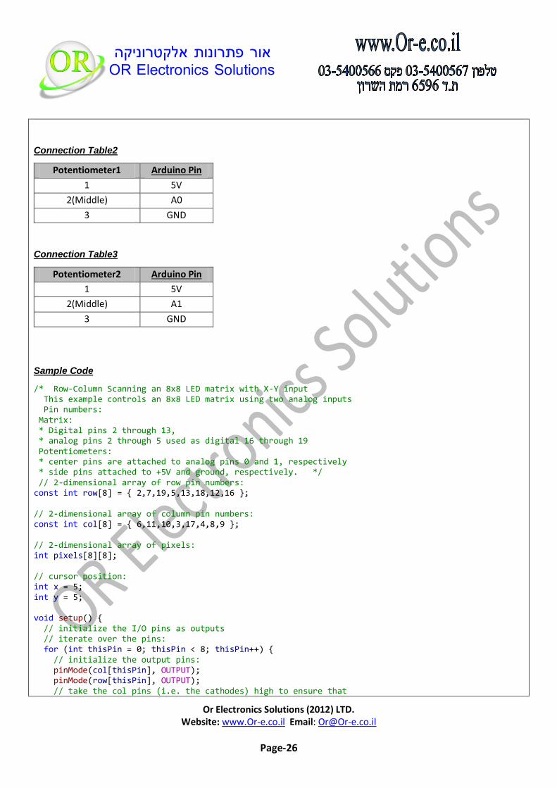
Connection Table2
Potentiometer1 Arduino Pin
1 5V
2(Middle) A0
3 GND
Connection Table3
Potentiometer2 Arduino Pin
1 5V
2(Middle) A1
3 GND
Sample Code
/* Row-Column Scanning an 8x8 LED matrix with X-Y input This example controls an 8x8 LED matrix using two analog inputs Pin numbers: Matrix: * Digital pins 2 through 13, * analog pins 2 through 5 used as digital 16 through 19 Potentiometers: * center pins are attached to analog pins 0 and 1, respectively * side pins attached to +5V and ground, respectively. */ // 2-dimensional array of row pin numbers: const int row[8] = { 2,7,19,5,13,18,12,16 }; // 2-dimensional array of column pin numbers: const int col[8] = { 6,11,10,3,17,4,8,9 }; // 2-dimensional array of pixels: int pixels[8][8]; // cursor position: int x = 5; int y = 5; void setup() { // initialize the I/O pins as outputs // iterate over the pins: for (int thisPin = 0; thisPin < 8; thisPin++) { // initialize the output pins: pinMode(col[thisPin], OUTPUT); pinMode(row[thisPin], OUTPUT); // take the col pins (i.e. the cathodes) high to ensure that

Or Electronics Solutions (2012) LTD. Website: www.Or-e.co.il Email: [email protected]
Page-27
// the LEDS are off: digitalWrite(col[thisPin], HIGH); } // initialize the pixel matrix: for (int x = 0; x < 8; x++) { for (int y = 0; y < 8; y++) { pixels[x][y] = HIGH; } } } void loop() { // read input: readSensors(); // draw the screen: refreshScreen(); } void readSensors() { // turn off the last position: pixels[x][y] = HIGH; // read the sensors for X and Y values: x = 7 - map(analogRead(A0), 0, 1023, 0, 7); y = map(analogRead(A1), 0, 1023, 0, 7); // set the new pixel position low so that the LED will turn on // in the next screen refresh: pixels[x][y] = LOW; } void refreshScreen() { // iterate over the rows (anodes): for (int thisRow = 0; thisRow < 8; thisRow++) { // take the row pin (anode) high: digitalWrite(row[thisRow], HIGH); // iterate over the cols (cathodes): for (int thisCol = 0; thisCol < 8; thisCol++) { // get the state of the current pixel; int thisPixel = pixels[thisRow][thisCol]; // when the row is HIGH and the col is LOW, // the LED where they meet turns on: digitalWrite(col[thisCol], thisPixel); // turn the pixel off: if (thisPixel == LOW) { digitalWrite(col[thisCol], HIGH); } } // take the row pin low to turn off the whole row: digitalWrite(row[thisRow], LOW); } }
Or Electronics Solutions (2012) LTD. Website: www.Or-e.co.il Email: [email protected]
Page-28
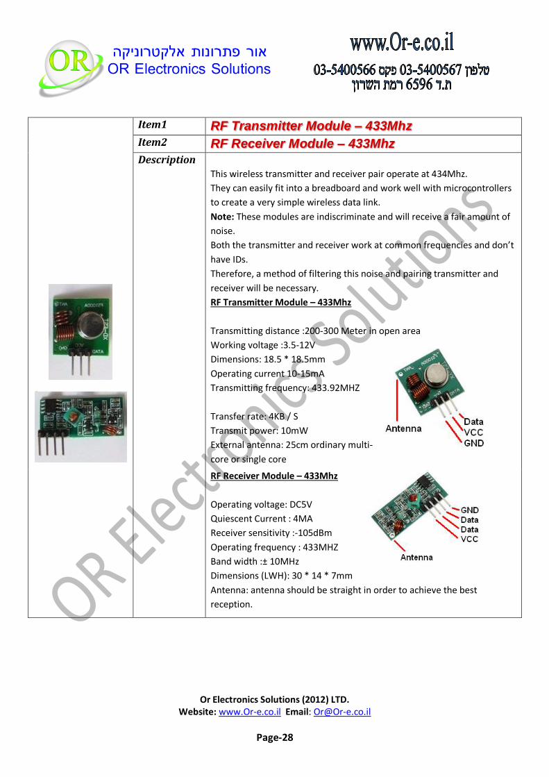
RF Transmitter Module – 433Mhz Item1
RF Receiver Module – 433Mhz Item2
This wireless transmitter and receiver pair operate at 434Mhz.
They can easily fit into a breadboard and work well with microcontrollers
to create a very simple wireless data link.
Note: These modules are indiscriminate and will receive a fair amount of
noise.
Both the transmitter and receiver work at common frequencies and don’t
have IDs.
Therefore, a method of filtering this noise and pairing transmitter and
receiver will be necessary.
RF Transmitter Module – 433Mhz
Transmitting distance :200-300 Meter in open area
Working voltage :3.5-12V
Dimensions: 18.5 * 18.5mm
Operating current 10-15mA
Transmitting frequency: 433.92MHZ
Transfer rate: 4KB / S
Transmit power: 10mW
External antenna: 25cm ordinary multi-
core or single core
Description
RF Receiver Module – 433Mhz
Operating voltage: DC5V
Quiescent Current : 4MA
Receiver sensitivity :-105dBm
Operating frequency : 433MHZ
Band width :± 10MHz
Dimensions (LWH): 30 * 14 * 7mm
Antenna: antenna should be straight in order to achieve the best
reception.
Or Electronics Solutions (2012) LTD. Website: www.Or-e.co.il Email: [email protected]
Page-29
Experiment
Links : Virtual Wire Library Download
In This Sample Code we use 2 Arduino boards :
Arduino board connected to transmitter module
Arduino board connected to receiver module
Transmitter
When the voltage is 5V, the communication distance is around 100 meters in open space.
Increasing the voltage will increase the communication distance.
The external antenna can use 25 cm long wire.
Transmitter Connection Table
Transmitter Code
#include <VirtualWire.h> #define DataPin 12 #define LedPin 13 void setup() { Serial.begin(9600); // Debugging only Serial.println("setup"); // Initialise the IO and ISR vw_set_ptt_inverted(true); // Required for DR3100 vw_set_tx_pin(DataPin); pinMode(LedPin, OUTPUT); vw_setup(2000); // Bits per sec } void loop() { const char *msg = "hello"; digitalWrite(LedPin, true); // Flash a light to show transmitting vw_send((uint8_t *)msg, strlen(msg)); vw_wait_tx(); // Wait until the whole message is gone digitalWrite(LedPin, false); delay(200); }
Transmitter Arduino Pin
Data Pin 12
VCC 5V
GND GND
Or Electronics Solutions (2012) LTD. Website: www.Or-e.co.il Email: [email protected]
Page-30
Receiver :
Receiver Connection Table
Receiver Arduino Pin
Data Pin 12
VCC 5V
GND GND
Receiver Code
#include <VirtualWire.h> #define DataPin 12 #define LedPin 13 void setup() { Serial.begin(9600); // Debugging only Serial.println("setup"); // Initialise the IO and ISR vw_set_ptt_inverted(true); // Required for DR3100 vw_set_rx_pin(DataPin); vw_setup(2000); // Bits per sec pinMode(LedPin, OUTPUT); vw_rx_start(); // Start the receiver PLL running } void loop() { uint8_t buf[VW_MAX_MESSAGE_LEN]; uint8_t buflen = VW_MAX_MESSAGE_LEN; if (vw_get_message(buf, &buflen)) // Non-blocking { int i; digitalWrite(LedPin, true); // Flash a light to show received good message Serial.print("Got: ");// Message with a good checksum received, dump it. for (i = 0; i < buflen; i++) { Serial.print(buf[i], BYTE); Serial.print(" "); } Serial.println(""); digitalWrite(LedPin, false); } }

Or Electronics Solutions (2012) LTD. Website: www.Or-e.co.il Email: [email protected]
Page-31
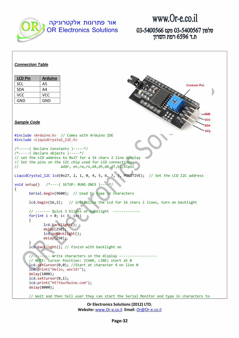
Serial Character LCD 16L2 Module (I2C) Item
This is a basic 16 character by 2 line display with a Backpack Board for I2C
Connection.
Utilizes the extremely common HD44780 parallel interface chipset
With this I2C interface LCD module, you will be able to realize data display
via only 2 wires.
Specification:
Backpack Board Based On The PCF8540
I2C Address: 0x27 (A0-A2 are Pulled-up onboard )
Supply voltage: 5V
I2C Addressing:
A2 A1 A0 LCD Add.
Open ("1") Open ("1") Open ("1") 0x27 (Default)
Open ("1") Open ("1") Close ("0") 0x26
Open ("1") Close ("0") Open ("1") 0x25
Open ("1") Close("0") Close ("0") 0x24
Close("0") Open ("1") Open ("1") 0x23
Close ("0") Open ("1") Close ("0") 0x22
Close ("0") Close ("0") Open ("1") 0x21
Close ("0") Close ("0") Close ("0") 0x20
Links:
Serial Character LCD 16L2 Module (I2C)
Description
Or Electronics Solutions (2012) LTD. Website: www.Or-e.co.il Email: [email protected]
Page-32
Connection Table
LCD Pin Arduino
SCL A5
SDA A4
VCC VCC
GND GND
Sample Code
#include <Arduino.h> // Comes with Arduino IDE #include <LiquidCrystal_I2C.h> /*-----( Declare Constants )-----*/ /*-----( Declare objects )-----*/ // set the LCD address to 0x27 for a 16 chars 2 line display // Set the pins on the I2C chip used for LCD connections: // addr, en,rw,rs,d4,d5,d6,d7,bl,blpol LiquidCrystal_I2C lcd(0x27, 2, 1, 0, 4, 5, 6, 7, 3, POSITIVE); // Set the LCD I2C address void setup() /*----( SETUP: RUNS ONCE )----*/ { Serial.begin(9600); // Used to type in characters lcd.begin(16,2); // initialize the lcd for 16 chars 2 lines, turn on backlight // ------- Quick 3 blinks of backlight ------------- for(int i = 0; i< 3; i++) { lcd.backlight(); delay(250); lcd.noBacklight(); delay(250); } lcd.backlight(); // finish with backlight on //-------- Write characters on the display ------------------ // NOTE: Cursor Position: (CHAR, LINE) start at 0 lcd.setCursor(0,0); //Start at character 4 on line 0 lcd.print("Hello, world!"); delay(1000); lcd.setCursor(0,1); lcd.print("HI!YourDuino.com"); delay(8000); // Wait and then tell user they can start the Serial Monitor and type in characters to

Or Electronics Solutions (2012) LTD. Website: www.Or-e.co.il Email: [email protected]
Page-33
// Display. (Set Serial Monitor option to "No Line Ending") lcd.clear(); lcd.setCursor(0,0); //Start at character 0 on line 0 lcd.print("Use Serial Mon"); lcd.setCursor(0,1); lcd.print("Type to display"); }/*--(end setup )---*/ void loop() /*----( LOOP: RUNS CONSTANTLY )----*/ { { // when characters arrive over the serial port... if (Serial.available()) { // wait a bit for the entire message to arrive delay(100); // clear the screen lcd.clear(); // read all the available characters while (Serial.available() > 0) { // display each character to the LCD lcd.write(Serial.read()); } } } }/* --(end main loop )-- */
Or Electronics Solutions (2012) LTD. Website: www.Or-e.co.il Email: [email protected]
Page-34
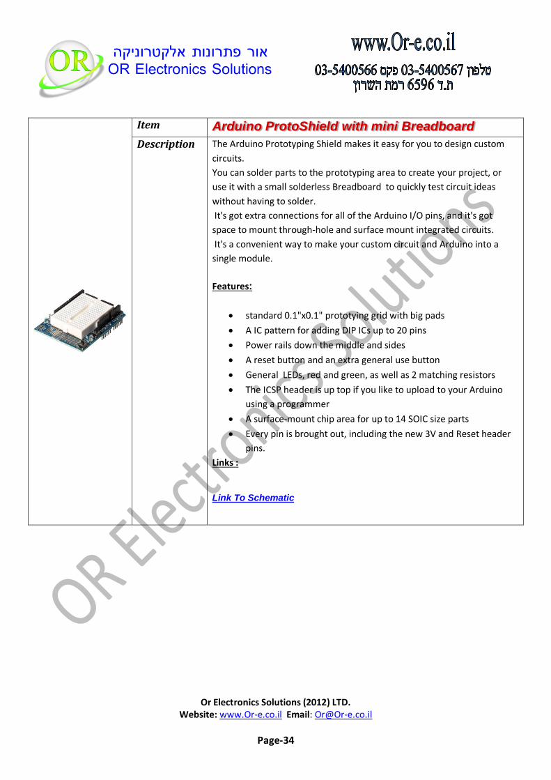
Arduino ProtoShield with mini Breadboard Item
The Arduino Prototyping Shield makes it easy for you to design custom
circuits.
You can solder parts to the prototyping area to create your project, or
use it with a small solderless Breadboard to quickly test circuit ideas
without having to solder.
It's got extra connections for all of the Arduino I/O pins, and it's got
space to mount through-hole and surface mount integrated circuits.
It's a convenient way to make your custom circuit and Arduino into a
single module.
Features:
standard 0.1"x0.1" prototying grid with big pads
A IC pattern for adding DIP ICs up to 20 pins
Power rails down the middle and sides
A reset button and an extra general use button
General LEDs, red and green, as well as 2 matching resistors
The ICSP header is up top if you like to upload to your Arduino
using a programmer
A surface-mount chip area for up to 14 SOIC size parts
Every pin is brought out, including the new 3V and Reset header
pins.
Links :
Link To Schematic
Description

Or Electronics Solutions (2012) LTD. Website: www.Or-e.co.il Email: [email protected]
Page-35
Arduino Sound Sensor Module Item
Sound module is most sensitive to the ambient sound intensity is
generally used to detect the intensity of the sound of the surrounding
environment.
Module at ambient sound intensity less than the set threshold value,
OUT output is high.
When the outside ambient sound intensity exceeds the threshold value is
set The module OUT output is LOW.
The 3 board digital output OUT is directly connected with the
microcontroller to detect high and low.
Features:
Adjustable sensitivity potentiometer.
Operating voltage 3.3V-5V.
Digital Output.
Description
Or Electronics Solutions (2012) LTD. Website: www.Or-e.co.il Email: [email protected]
Page-36
Pin description:
Sound
Sensor
VCC External 3.3-5 V
GND Reference GND
OUT Arduino Digital Input
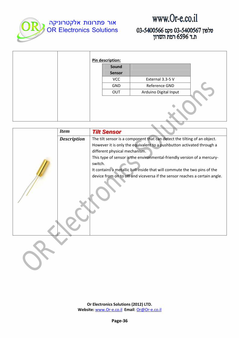
Tilt Sensor Item
The tilt sensor is a component that can detect the tilting of an object.
However it is only the equivalent to a pushbutton activated through a
different physical mechanism.
This type of sensor is the environmental-friendly version of a mercury-
switch.
It contains a metallic ball inside that will commute the two pins of the
device from on to off and viceversa if the sensor reaches a certain angle.
Description

Or Electronics Solutions (2012) LTD. Website: www.Or-e.co.il Email: [email protected]
Page-37
Experiment
Connection Table1
Tilt Sensor Arduino Pin
1 GND
2 D2
Connection Table2
Resistor 1K Ohm Arduino Pin
1 D2
2 VCC
Sample Code
int inPin = 2; // the number of the input pin int outPin = 13; // the number of the output pin int LEDstate = HIGH; // the current state of the output pin int reading; // the current reading from the input pin int previous = LOW; // the previous reading from the input pin // the follow variables are long's because the time, measured in miliseconds, // will quickly become a bigger number than can be stored in an int. long time = 0; // the last time the output pin was toggled long debounce = 50; // the debounce time, increase if the output flickers void setup() { pinMode(inPin, INPUT);

Or Electronics Solutions (2012) LTD. Website: www.Or-e.co.il Email: [email protected]
Page-38
digitalWrite(inPin, HIGH); // turn on the built in pull-up resistor pinMode(outPin, OUTPUT); } void loop() { int switchstate; reading = digitalRead(inPin); // If the switch changed, due to bounce or pressing... if (reading != previous) { // reset the debouncing timer time = millis(); } if ((millis() - time) > debounce) { // whatever the switch is at, its been there for a long time // so lets settle on it! switchstate = reading; // Now invert the output on the pin13 LED if (switchstate == HIGH) LEDstate = LOW; else LEDstate = HIGH; } digitalWrite(outPin, LEDstate); // Save the last reading so we keep a running tally previous = reading; }
Or Electronics Solutions (2012) LTD. Website: www.Or-e.co.il Email: [email protected]
Page-39
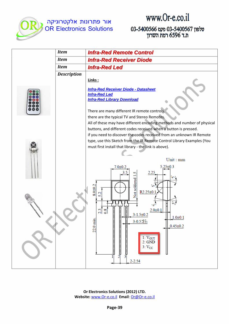
Infra-Red Remote Control Item
Infra-Red Receiver Diode Item
Infra-Red Led Item
Links :
Infra-Red Receiver Diode - Datasheet
Infra-Red Led
Infra-Red Library Download
There are many different IR remote controls.
there are the typical TV and Stereo Remotes.
All of these may have different encoding methods and number of physical
buttons, and different codes received when a button is pressed.
if you need to discover the codes received from an unknown IR Remote
type, use this Sketch from the IR Remote Control Library Examples (You
must first install that library - the link is above).
Description
Or Electronics Solutions (2012) LTD. Website: www.Or-e.co.il Email: [email protected]
Page-40
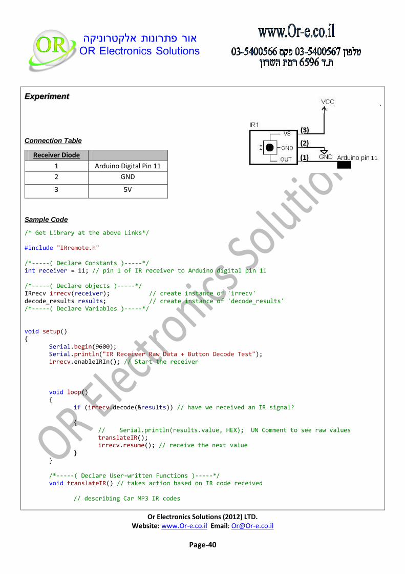
Experiment
Connection Table
Receiver Diode
1 Arduino Digital Pin 11
2 GND
3 5V
Sample Code
/* Get Library at the above Links*/ #include "IRremote.h" /*-----( Declare Constants )-----*/ int receiver = 11; // pin 1 of IR receiver to Arduino digital pin 11 /*-----( Declare objects )-----*/ IRrecv irrecv(receiver); // create instance of 'irrecv' decode_results results; // create instance of 'decode_results' /*-----( Declare Variables )-----*/ void setup() { Serial.begin(9600); Serial.println("IR Receiver Raw Data + Button Decode Test"); irrecv.enableIRIn(); // Start the receiver void loop() { if (irrecv.decode(&results)) // have we received an IR signal? { // Serial.println(results.value, HEX); UN Comment to see raw values translateIR(); irrecv.resume(); // receive the next value } } /*-----( Declare User-written Functions )-----*/ void translateIR() // takes action based on IR code received // describing Car MP3 IR codes

Or Electronics Solutions (2012) LTD. Website: www.Or-e.co.il Email: [email protected]
Page-41
{ switch(results.value) { case 0xFFA25D: Serial.println(" CH- "); break; case 0xFF629D: Serial.println(" CH "); break; case 0xFFE21D: Serial.println(" CH+ "); break; case 0xFF22DD: Serial.println(" PREV "); break; case 0xFF02FD: Serial.println(" NEXT "); break; case 0xFFC23D: Serial.println(" PLAY/PAUSE "); break; case 0xFFE01F: Serial.println(" VOL- "); break; case 0xFFA857: Serial.println(" VOL+ "); break; case 0xFF906F: Serial.println(" EQ "); break; case 0xFF6897: Serial.println(" 0 "); break; case 0xFF9867: Serial.println(" 100+ "); break; case 0xFFB04F: Serial.println(" 200+ "); break; case 0xFF30CF: Serial.println(" 1 "); break; case 0xFF18E7: Serial.println(" 2 "); break; case 0xFF7A85: Serial.println(" 3 "); break; case 0xFF10EF: Serial.println(" 4 "); break; case 0xFF38C7: Serial.println(" 5 "); break; case 0xFF5AA5: Serial.println(" 6 "); break; case 0xFF42BD: Serial.println(" 7 "); break; case 0xFF4AB5: Serial.println(" 8 "); break; case 0xFF52AD: Serial.println(" 9 "); break; default: Serial.println(" other button "); } delay(500); } //END translateIR

Or Electronics Solutions (2012) LTD. Website: www.Or-e.co.il Email: [email protected]
Page-42
Push Button 12X12 Item1
Mini Push Button 6X6 Item2
The Arduino push
button is a small
and cheap single
pole single through
switch that can be
soldered on a PCB.
Arduino usually
uses those
switches as reset
buttons on their boards.
The push button closes a circuit when you press on it.
Perfect to be soldered on a board can be used as a reset switch
rated at 50 mA.
Description

Or Electronics Solutions (2012) LTD. Website: www.Or-e.co.il Email: [email protected]
Page-43
Experiment
Connection Table
SW Arduino
1 Pin 2
2 GND
Sample Code
//button wired pin 2 to ground directly constants used here to set pin numbers: const int buttonPin = 2; //pushbutton pin const int ledPin = 13; // LED pin int buttonState = 0; // variable for reading the pushbutton status void setup() { Serial.begin(9600); //initialize the serial port pinMode(ledPin, OUTPUT); // initialize the LED pin as an output pinMode(buttonPin, INPUT); // initialize the pushbutton pin as an input digitalWrite(buttonPin, HIGH); //Use Chip Internal Pull-up Resistor(10k) } void loop(){ buttonState = digitalRead(buttonPin); // read the state of the pushbutton // check if the pushbutton is pressed or not // if it is, the buttonState is HIGH: if (buttonState == HIGH) { digitalWrite(ledPin, LOW); Serial.println("button not pushed "); } else { // turn LED on digitalWrite(ledPin, HIGH); Serial.println("button pushed"); } }
Or Electronics Solutions (2012) LTD. Website: www.Or-e.co.il Email: [email protected]
Page-44
Red Led – 5mm Item1
Green Led – 5mm Item2
Blue Led – 5mm Item3
Yellow Led – 5mm Item4
White Led – 5mm Item5
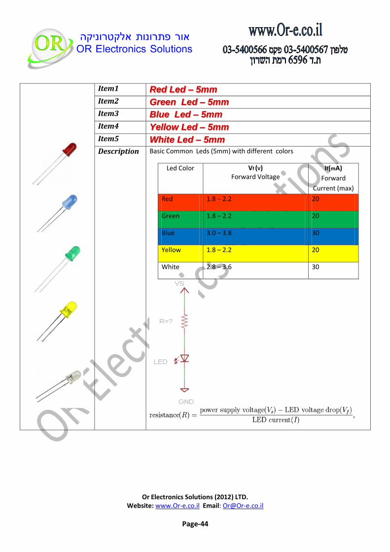
Basic Common Leds (5mm) with different colors
Led Color Vf (V) Forward Voltage
If(mA)
Forward
Current (max)
Red 1.8 – 2.2 20
Green 1.8 – 2.2 20
Blue 3.0 – 3.8 30
Yellow 1.8 – 2.2 20
White 2.8 – 3.6 30
Description

Or Electronics Solutions (2012) LTD. Website: www.Or-e.co.il Email: [email protected]
Page-45
Experiment
Connection
Connect Red Led and Green Led Thru resistor 1KOhm as
shown in figure
Sample Code
/* Connect Red Led to Pin 12 With 1Kohm resistor and Green Led to Pin 11 with 1Kohm as described .*/ int redPin = 12; int greenPin = 11; void setup() // run once, when the sketch starts { pinMode(redPin, OUTPUT); pinMode(greenPin, OUTPUT); } void loop() // run over and over again { digitalWrite(redPin, HIGH); // sets the Red LED on digitalWrite(greenPin, LOW); // sets the Green LED off delay(500); // waits for half a second digitalWrite(redPin, LOW); // sets the Red LED off digitalWrite(greenPin, HIGH); // sets the Green LED on delay(500); // waits for half a second }
Or Electronics Solutions (2012) LTD. Website: www.Or-e.co.il Email: [email protected]
Page-46
Keypad 4x4 Matrix Item
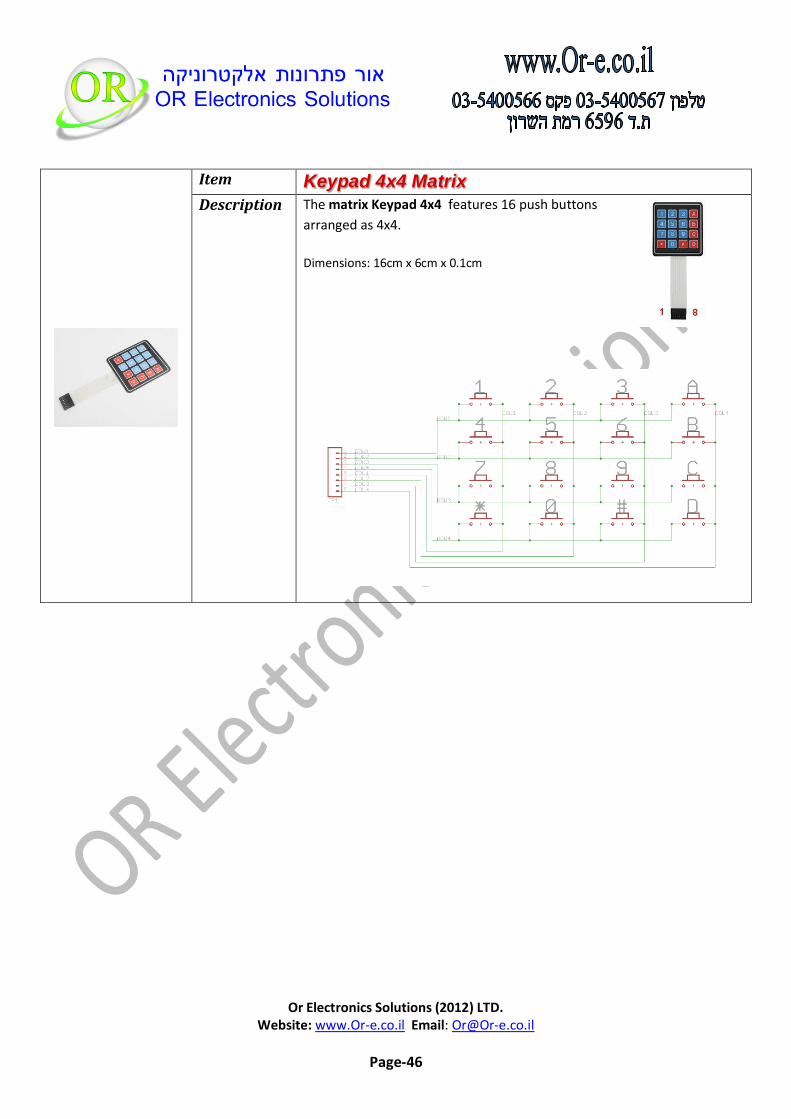
The matrix Keypad 4x4 features 16 push buttons
arranged as 4x4.
Dimensions: 16cm x 6cm x 0.1cm
Description
Or Electronics Solutions (2012) LTD. Website: www.Or-e.co.il Email: [email protected]
Page-47
Experiment
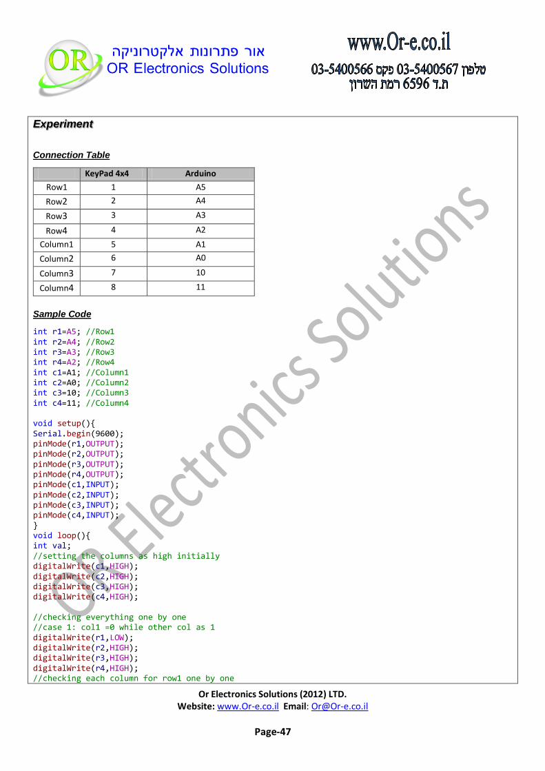
Connection Table
KeyPad 4x4 Arduino
Row1 1 A5
Row2 2 A4
Row3 3 A3
Row4 4 A2
Column1 5 A1
Column2 6 A0
Column3 7 10
Column4 8 11
Sample Code
int r1=A5; //Row1 int r2=A4; //Row2 int r3=A3; //Row3 int r4=A2; //Row4 int c1=A1; //Column1 int c2=A0; //Column2 int c3=10; //Column3 int c4=11; //Column4 void setup(){ Serial.begin(9600); pinMode(r1,OUTPUT); pinMode(r2,OUTPUT); pinMode(r3,OUTPUT); pinMode(r4,OUTPUT); pinMode(c1,INPUT); pinMode(c2,INPUT); pinMode(c3,INPUT); pinMode(c4,INPUT); } void loop(){ int val; //setting the columns as high initially digitalWrite(c1,HIGH); digitalWrite(c2,HIGH); digitalWrite(c3,HIGH); digitalWrite(c4,HIGH); //checking everything one by one //case 1: col1 =0 while other col as 1 digitalWrite(r1,LOW); digitalWrite(r2,HIGH); digitalWrite(r3,HIGH); digitalWrite(r4,HIGH); //checking each column for row1 one by one
Or Electronics Solutions (2012) LTD. Website: www.Or-e.co.il Email: [email protected]
Page-48
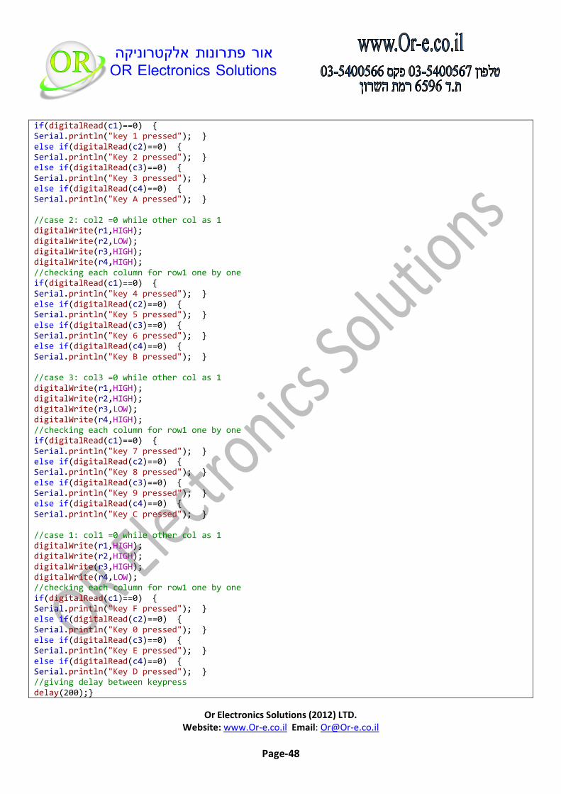
if(digitalRead(c1)==0) { Serial.println("key 1 pressed"); } else if(digitalRead(c2)==0) { Serial.println("Key 2 pressed"); } else if(digitalRead(c3)==0) { Serial.println("Key 3 pressed"); } else if(digitalRead(c4)==0) { Serial.println("Key A pressed"); } //case 2: col2 =0 while other col as 1 digitalWrite(r1,HIGH); digitalWrite(r2,LOW); digitalWrite(r3,HIGH); digitalWrite(r4,HIGH); //checking each column for row1 one by one if(digitalRead(c1)==0) { Serial.println("key 4 pressed"); } else if(digitalRead(c2)==0) { Serial.println("Key 5 pressed"); } else if(digitalRead(c3)==0) { Serial.println("Key 6 pressed"); } else if(digitalRead(c4)==0) { Serial.println("Key B pressed"); } //case 3: col3 =0 while other col as 1 digitalWrite(r1,HIGH); digitalWrite(r2,HIGH); digitalWrite(r3,LOW); digitalWrite(r4,HIGH); //checking each column for row1 one by one if(digitalRead(c1)==0) { Serial.println("key 7 pressed"); } else if(digitalRead(c2)==0) { Serial.println("Key 8 pressed"); } else if(digitalRead(c3)==0) { Serial.println("Key 9 pressed"); } else if(digitalRead(c4)==0) { Serial.println("Key C pressed"); } //case 1: col1 =0 while other col as 1 digitalWrite(r1,HIGH); digitalWrite(r2,HIGH); digitalWrite(r3,HIGH); digitalWrite(r4,LOW); //checking each column for row1 one by one if(digitalRead(c1)==0) { Serial.println("key F pressed"); } else if(digitalRead(c2)==0) { Serial.println("Key 0 pressed"); } else if(digitalRead(c3)==0) { Serial.println("Key E pressed"); } else if(digitalRead(c4)==0) { Serial.println("Key D pressed"); } //giving delay between keypress delay(200);}

Or Electronics Solutions (2012) LTD. Website: www.Or-e.co.il Email: [email protected]
Page-49
Rotary potentiometer 10k -Linear Item
Specifications
Type: Top Adjustment
Power: 1/2W
Resistance: 10K OHM
Type: Linear
Description
Experiment
Connection Table
Potensiometer Arduino
1 5V
2(Middle) 2
3 GND
Sample Code
/* Analog Read to LED turns on and off a light emitting diode(LED) connected to digital pin 13. The amount of time the LED will be on and off depends on the value obtained by analogRead(). In the easiest case we connect a potentiometer to analog pin 2. */ int potPin = 2;// input pin for the potentiometer int ledPin = 13; // select the pin for the LED int val = 0; void setup() { pinMode(ledPin, OUTPUT); } void loop() { val = analogRead(potPin);// read value from the sensor digitalWrite(ledPin, HIGH); // turn the ledPin on delay(val); // delay as pot. value digitalWrite(ledPin, LOW); // turn the ledPin off delay(val); // stop the program for some time }
Or Electronics Solutions (2012) LTD. Website: www.Or-e.co.il Email: [email protected]
Page-50
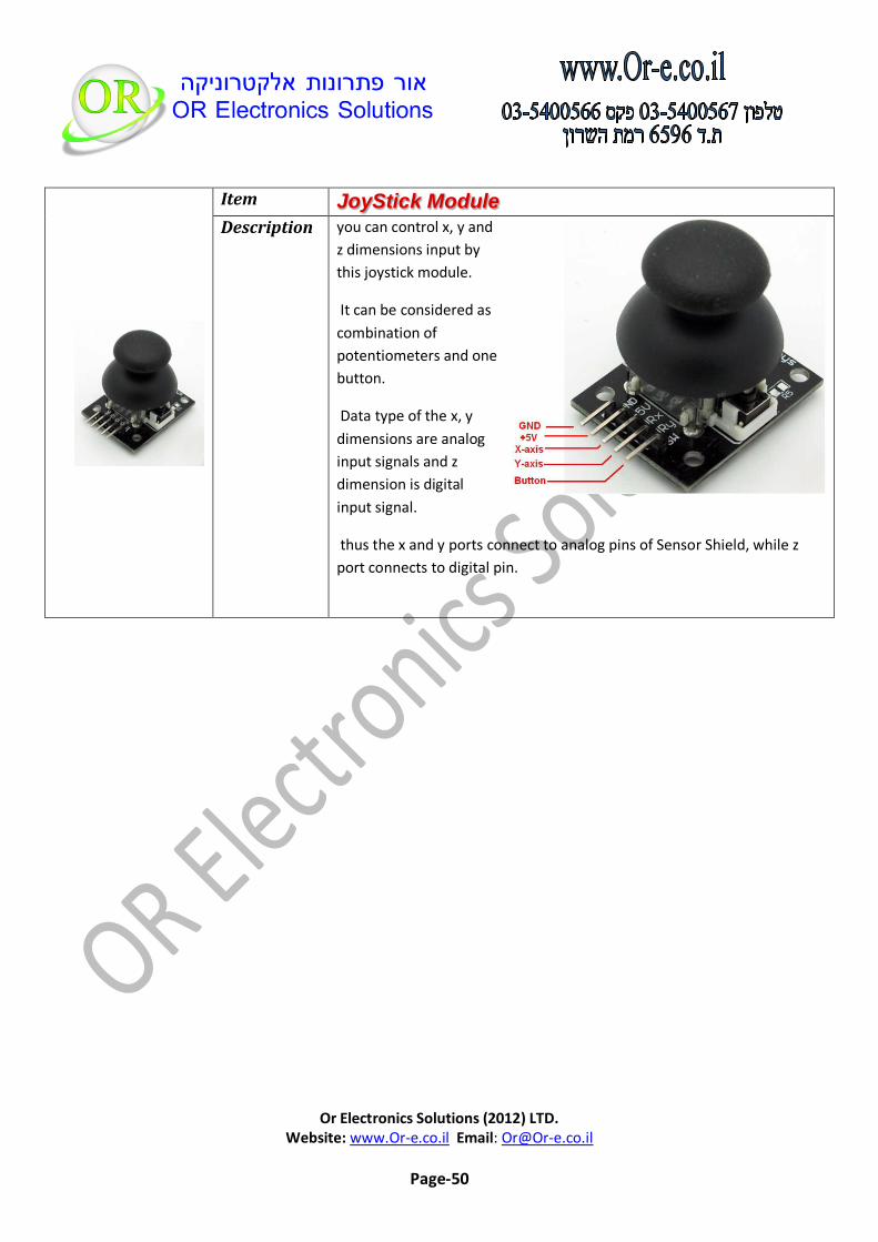
JoyStick Module Item
you can control x, y and
z dimensions input by
this joystick module.
It can be considered as
combination of
potentiometers and one
button.
Data type of the x, y
dimensions are analog
input signals and z
dimension is digital
input signal.
thus the x and y ports connect to analog pins of Sensor Shield, while z
port connects to digital pin.
Description

Or Electronics Solutions (2012) LTD. Website: www.Or-e.co.il Email: [email protected]
Page-51
Experiment
Connection Table
Joystick Arduino
GND GND
+5V 5V
VRx A0
VRy A1
SW D2
Sample Code
int JoyStick_X = 0; //x int JoyStick_Y = 1; //y int JoyStick_Button = 2; //Button void setup() { pinMode(JoyStick_X, INPUT); pinMode(JoyStick_Y, INPUT); pinMode(JoyStick_Button, INPUT); Serial.begin(9600); // 9600 bps } void loop() { int x,y,B; x=analogRead(JoyStick_X); y=analogRead(JoyStick_Y); B=digitalRead(JoyStick_Button); Serial.print(x ,DEC); Serial.print(","); Serial.print(y ,DEC); Serial.print(","); Serial.println(B ,DEC); delay(100); }
Or Electronics Solutions (2012) LTD. Website: www.Or-e.co.il Email: [email protected]
Page-52
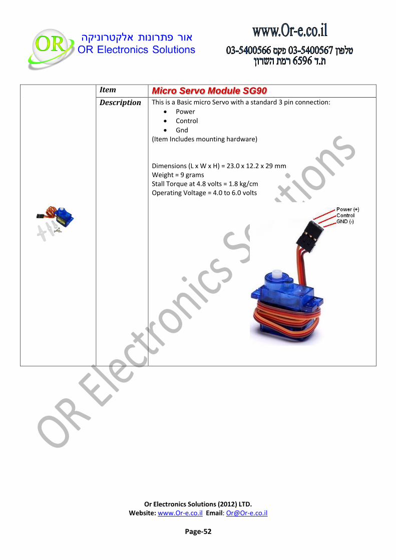
Micro Servo Module SG90 Item
This is a Basic micro Servo with a standard 3 pin connection:
Power
Control
Gnd (Item Includes mounting hardware) Dimensions (L x W x H) = 23.0 x 12.2 x 29 mm Weight = 9 grams Stall Torque at 4.8 volts = 1.8 kg/cm Operating Voltage = 4.0 to 6.0 volts
Description
Or Electronics Solutions (2012) LTD. Website: www.Or-e.co.il Email: [email protected]
Page-53
Experiment
Connection Table
Servo Connection
Power 5V
Control Arduino Digital Pin 9
GND GND
Sample Code
//Connect Power wire (Orange wire) to Arduino 5V //Connect Control wire (Red wire) to Arduino Pin 9 //Connect Control wire (Brown wire) to Arduino GND #include <Servo.h> Servo myservo; // create servo object to control a servo // a maximum of eight servo objects can be created int pos = 0; // variable to store the servo position void setup() { myservo.attach(9); // attaches the servo on pin 9 to the servo object } void loop() { for(pos = 0; pos < 180; pos += 1) // goes from 0 degrees to 180 degrees { // in steps of 1 degree myservo.write(pos); // tell servo to go to position in variable 'pos' delay(15); // waits 15ms for the servo to reach the position } for(pos = 180; pos>=1; pos-=1) // goes from 180 degrees to 0 degrees { myservo.write(pos); // tell servo to go to position in variable 'pos' delay(15); // waits 15ms for the servo to reach the position }
Or Electronics Solutions (2012) LTD. Website: www.Or-e.co.il Email: [email protected]
Page-54
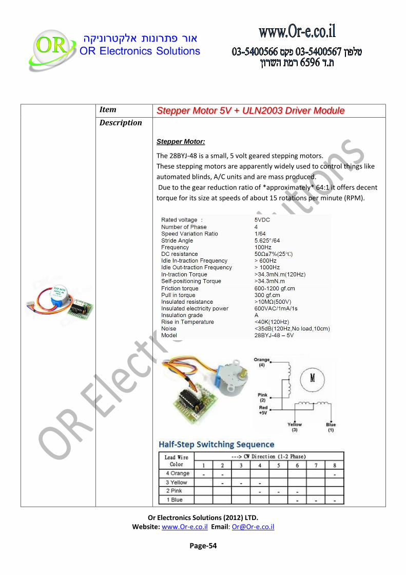
Stepper Motor 5V + ULN2003 Driver Module Item
Stepper Motor:
The 28BYJ-48 is a small, 5 volt geared stepping motors.
These stepping motors are apparently widely used to control things like
automated blinds, A/C units and are mass produced.
Due to the gear reduction ratio of *approximately* 64:1 it offers decent
torque for its size at speeds of about 15 rotations per minute (RPM).
Description

Or Electronics Solutions (2012) LTD. Website: www.Or-e.co.il Email: [email protected]
Page-55
ULN2003 Driver
Module:
The ULN2003 stepper
motor driver board
allows you to easily
control the 28BYJ-48
stepper motor from a
microcontroller, like
the Arduino Uno.
One side of the board
side has a 5 wire socket
where the cable from
the stepper motor
hooks up and 4 LEDs to
indicate which coil is currently powered.
On the side you have a motor on / off jumper (keep it on to enable power
to the stepper).
The two pins below the 4 resistors, is where you provide power to the
stepper.
Note that powering the stepper from the 5 V rail of the Arduino is not
recommended.
A separate 5-12 V 1 Amp power supply or battery pack should be used,
as the motor may drain more current than the microcontroller can handle
and could potentially damage it.
In the middle of the board we have the ULN2003 chip. At the bottom are
the 4 control inputs that should be connected to four Arduino digital pins.

Or Electronics Solutions (2012) LTD. Website: www.Or-e.co.il Email: [email protected]
Page-56
Experiment
Links : AccelStepper Library Download
Connection Table
ULN2003 Driver Module
Connection
IN1 Arduino Digital Pin 3
IN2 Arduino Digital Pin 4
IN3 Arduino Digital Pin 5
IN4 Arduino Digital Pin 6
Driver Power External 5-12V Power
Don’t forget to connect the GND of the External Power to the Arduino GND
Sample Code
#include <AccelStepper.h> #define HALFSTEP 8 // Motor pin definitions #define motorPin1 3 // IN1 on the ULN2003 driver 1 #define motorPin2 4 // IN2 on the ULN2003 driver 1 #define motorPin3 5 // IN3 on the ULN2003 driver 1 #define motorPin4 6 // IN4 on the ULN2003 driver 1 // Initialize with pin sequence IN1-IN3-IN2-IN4 for using the AccelStepper with 28BYJ-48 AccelStepper stepper1(HALFSTEP, motorPin1, motorPin3, motorPin2, motorPin4); void setup() { stepper1.setMaxSpeed(1000.0); stepper1.setAcceleration(100.0); stepper1.setSpeed(200); stepper1.moveTo(20000); }//--(end setup )--- void loop() { //Change direction when the stepper reaches the target position if (stepper1.distanceToGo() == 0) { stepper1.moveTo(-stepper1.currentPosition()); } stepper1.run(); }

Or Electronics Solutions (2012) LTD. Website: www.Or-e.co.il Email: [email protected]
Page-57
Transistor - NPN (2N3904) Item1
Transistor - PNP (2N3906) Item2
These are very common, high
quality BJT NPN and PNP
transistors.
Link To Product Page
Link To Product Page
Description
Or Electronics Solutions (2012) LTD. Website: www.Or-e.co.il Email: [email protected]
Page-58
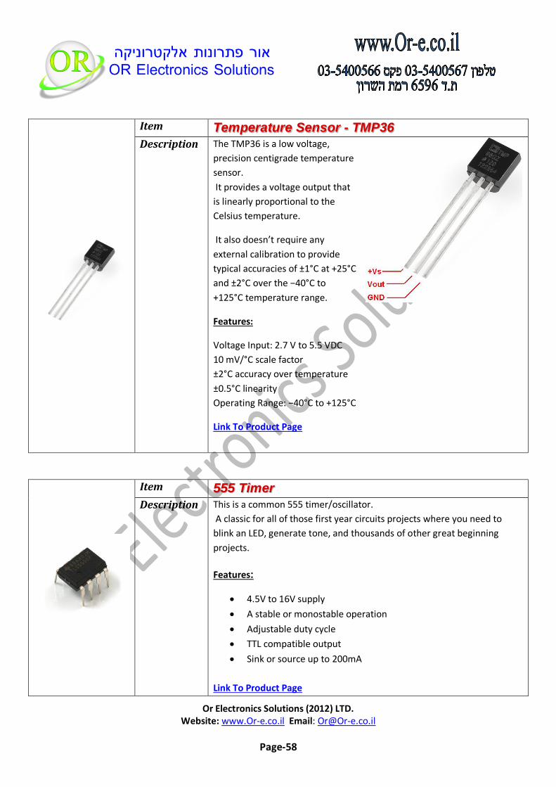
Temperature Sensor - TMP36 Item
The TMP36 is a low voltage,
precision centigrade temperature
sensor.
It provides a voltage output that
is linearly proportional to the
Celsius temperature.
It also doesn’t require any
external calibration to provide
typical accuracies of ±1°C at +25°C
and ±2°C over the −40°C to
+125°C temperature range.
Features:
Voltage Input: 2.7 V to 5.5 VDC
10 mV/°C scale factor
±2°C accuracy over temperature
±0.5°C linearity
Operating Range: −40°C to +125°C
Link To Product Page
Description
555 Timer Item
This is a common 555 timer/oscillator.
A classic for all of those first year circuits projects where you need to
blink an LED, generate tone, and thousands of other great beginning
projects.
Features:
4.5V to 16V supply
A stable or monostable operation
Adjustable duty cycle
TTL compatible output
Sink or source up to 200mA
Link To Product Page
Description
Or Electronics Solutions (2012) LTD. Website: www.Or-e.co.il Email: [email protected]
Page-59
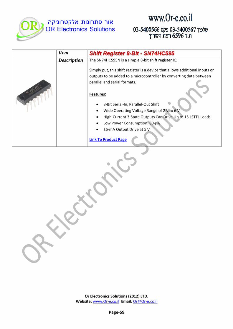
Shift Register 8-Bit - SN74HC595 Item
The SN74HC595N is a simple 8-bit shift register IC.
Simply put, this shift register is a device that allows additional inputs or
outputs to be added to a microcontroller by converting data between
parallel and serial formats.
Features:
8-Bit Serial-In, Parallel-Out Shift
Wide Operating Voltage Range of 2 V to 6 V
High-Current 3-State Outputs Can Drive Up to 15 LSTTL Loads
Low Power Consumption: 80-μA
±6-mA Output Drive at 5 V
Link To Product Page
Description

Or Electronics Solutions (2012) LTD. Website: www.Or-e.co.il Email: [email protected]
Page-60
Experiment
Connection Table
SN74HC595 Signal
SN74HC595 Pin
Connection
GND 8 GND
VCC 16 VCC
OE 13 GND
MR 10 VCC
DS 14 Arduino Digital Pin 11
SH_CP 11 Arduino Digital Pin 12
ST_CP 12 Arduino Digital Pin 8
Q0-Q7 1-7,15 Serial Resistor and Led (See Attached Scheme)
Connection Scheme

Or Electronics Solutions (2012) LTD. Website: www.Or-e.co.il Email: [email protected]
Page-61
Sample Code
// Code for using a 74HC595 Shift Register // to count from 0 to 255 //Pin connected to ST_CP of 74HC595 int latchPin = 8; //Pin connected to SH_CP of 74HC595 int clockPin = 12; ////Pin connected to DS of 74HC595 int dataPin = 11; void setup() { //set pins to output so you can control the shift register pinMode(latchPin, OUTPUT); pinMode(clockPin, OUTPUT); pinMode(dataPin, OUTPUT); } void loop() { // count from 0 to 255 and display the number // on the LEDs for (int numberToDisplay = 0; numberToDisplay < 256; numberToDisplay++) { // take the latchPin low so // the LEDs don't change while you're sending in bits: digitalWrite(latchPin, LOW); // shift out the bits: shiftOut(dataPin, clockPin, MSBFIRST, numberToDisplay); //take the latch pin high so the LEDs will light up: digitalWrite(latchPin, HIGH); // pause before next value: delay(500); } }
Diode Small Signal - 1N4148 Item
This is a very common signal diode - 1N4148. Use this for signals up to
200mA of current.
Link To Product Page
Description

Or Electronics Solutions (2012) LTD. Website: www.Or-e.co.il Email: [email protected]
Page-62
Screw Terminals 2.54mm Pitch (2-Pin) Item1
Screw Terminals 2.54mm Pitch (3-Pin) Item2
These are simple 2-position and 3-position screw terminals with 2.54mm
pitch pins.
Rated up to 150V @ 6A, this terminal can accept 30 to 18AWG wire.
The 2.54mm pitch will line up with standard 0.1" perf.
Description
Screw Driver (2 In 1) Item
Mini 2 in 1 Slotted and Phillips Metal Screwdriver Tool!
This 2 in 1 Screwdriver combine Philips Screwdriver and Slotted
Screwdriver into a single unit!
With double end tip with metal for more convenience and efficiency of
operating, you can use it as a Slotted Screwdriver and a Phillips
Screwdriver according to your needed.
Metal body features with yellow plastic handle, just insert two ends of
the handle respectively, and two-way screwdriver is ready to use.
Use this Metal Screwdriver Tool for precision repair works like phone
repair, laptops, handheld electronics and many other devices.
Mini 2 in 1 Slotted and Phillips Metal Screwdriver Tool!
Length: 5 1/4(shaft included).
Two-way tips include 3mm slotted and 3mm philips screwdriver bit.
Description