plate anlaysis
TRANSCRIPT

8/4/2019 Plate Anlaysis
http://slidepdf.com/reader/full/plate-anlaysis 1/96
Basics of Finite Element Analysis
What is FEA ?
A complex problem is divided into a smaller and
simpler problems that can be solved by using theexisting knowledge of mechanics of materials and
mathematical tools
Ken Youssefi Mechanical Engineering Dept 1
Why FEA ?
Modern mechanical design involves complicated shapes,
sometimes made of different materials that as a whole
cannot be solved by existing mathematical tools.
Engineers need the FEA to evaluate their designs
8/4/2019 Plate Anlaysis
http://slidepdf.com/reader/full/plate-anlaysis 2/96
Basics of Finite Element Analysis
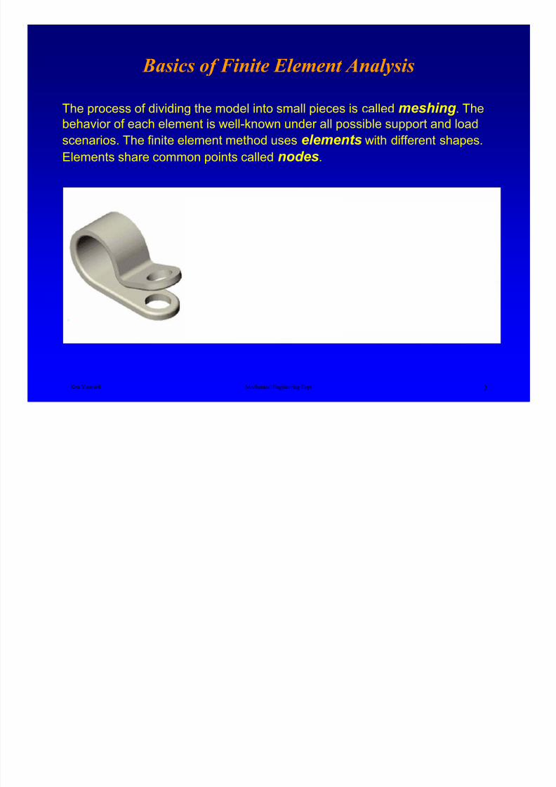
The process of dividing the model into small pieces is called meshing . The
behavior of each element is well-known under all possible support and load
scenarios. The finite element method uses elements with different shapes.
Elements share common points called nodes.
Ken Youssefi Mechanical Engineering Dept 2

8/4/2019 Plate Anlaysis
http://slidepdf.com/reader/full/plate-anlaysis 3/96
History of Finite Element Analysis
Finite Element Analysis (FEA) was first developed in 1943 by R.
Courant, who utilized the Ritz method of numerical analysis and
minimization of variational calculus.
A paper published in 1956 by M. J. Turner, R. W. Clough, H. C.
Martin, and L. J. Topp established a broader definition of
numerical analysis. The paper centered on the "stiffness and
Ken Youssefi Mechanical Engineering Dept 3
deflection of complex structures".
By the early 70's, FEA was limited to expensive mainframe
computers generally owned by the aeronautics, automotive,
defense, and nuclear industries. Since the rapid decline in the costof computers and the phenomenal increase in computing power,
FEA has been developed to an incredible precision.
8/4/2019 Plate Anlaysis
http://slidepdf.com/reader/full/plate-anlaysis 4/96
Basics of Finite Element Analysis
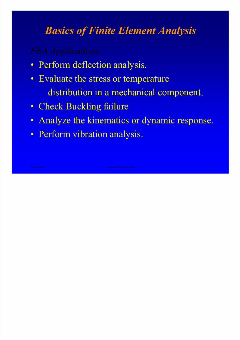
FEA Applications
• Perform deflection analysis.• Evaluate the stress or temperature
Ken Youssefi Mechanical Engineering Dept 4
.• Check Buckling failure
• Analyze the kinematics or dynamic response.
• Perform vibration analysis.
8/4/2019 Plate Anlaysis
http://slidepdf.com/reader/full/plate-anlaysis 5/96
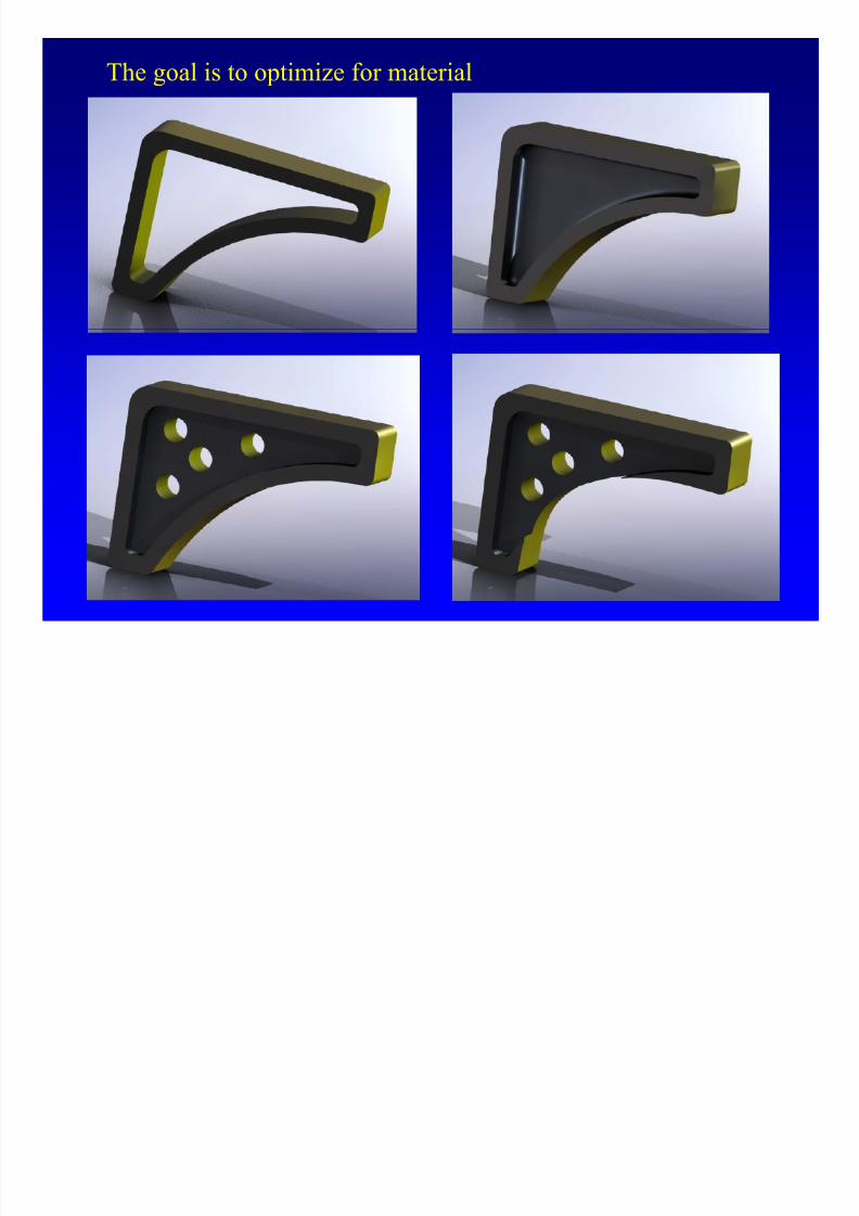
The goal is to optimize for material
8/4/2019 Plate Anlaysis
http://slidepdf.com/reader/full/plate-anlaysis 6/96
Basics of Finite Element Analysis
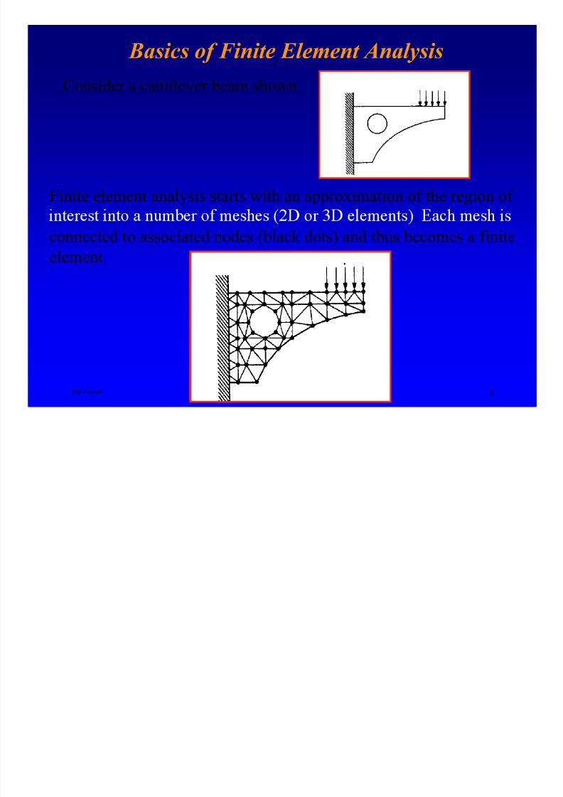
Consider a cantilever beam shown.
Finite element analysis starts with an approximation of the region of
Ken Youssefi Mechanical Engineering Dept 6
.
connected to associated nodes (black dots) and thus becomes a finite
element.
8/4/2019 Plate Anlaysis
http://slidepdf.com/reader/full/plate-anlaysis 7/96
Basics of Finite Element Analysis
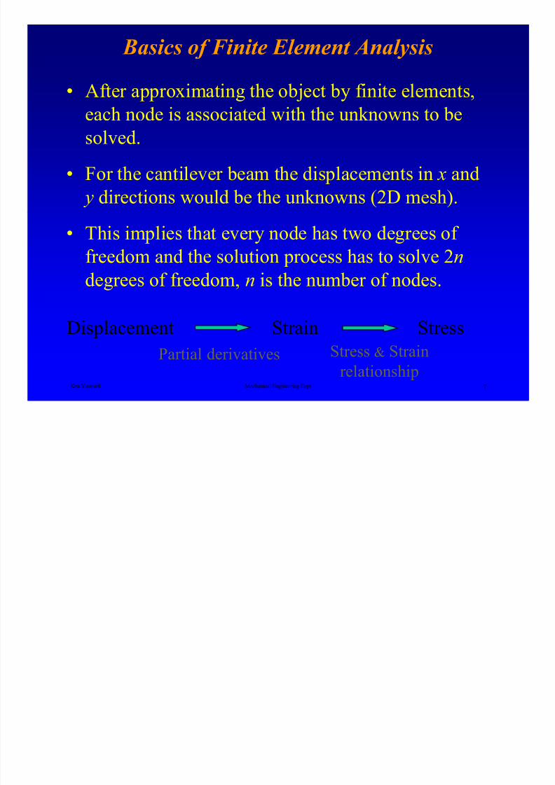
• After approximating the object by finite elements,
each node is associated with the unknowns to be
solved.
• For the cantilever beam the displacements in x and
y directions would be the unknowns (2D mesh).
Ken Youssefi Mechanical Engineering Dept 7
• This implies that every node has two degrees of
freedom and the solution process has to solve 2n
degrees of freedom, n is the number of nodes.
Displacement Strain
Partial derivatives
Stress
Stress & Strain
relationship
8/4/2019 Plate Anlaysis
http://slidepdf.com/reader/full/plate-anlaysis 8/96
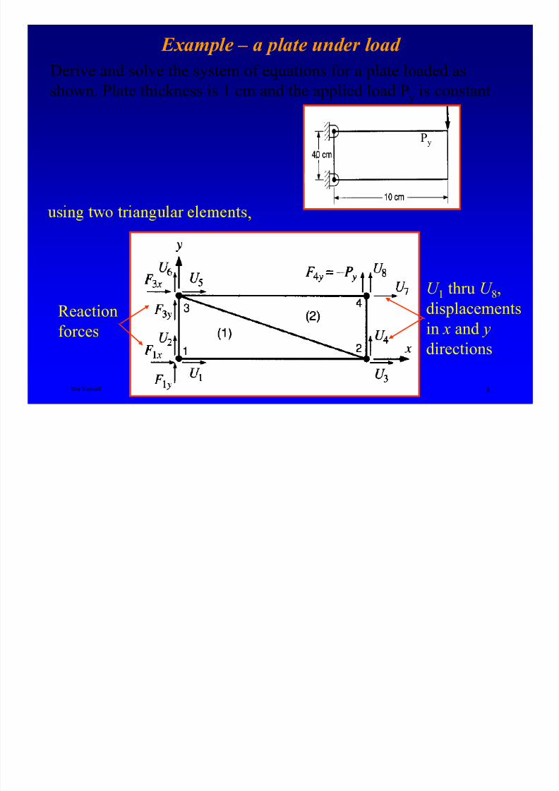
Example – a plate under load
Derive and solve the system of equations for a plate loaded asshown. Plate thickness is 1 cm and the applied load Py is constant
Py
.
Ken Youssefi Mechanical Engineering Dept 8
,
Reaction
forces
U 1 thru U 8,
displacements
in x and y
directions
8/4/2019 Plate Anlaysis
http://slidepdf.com/reader/full/plate-anlaysis 9/96
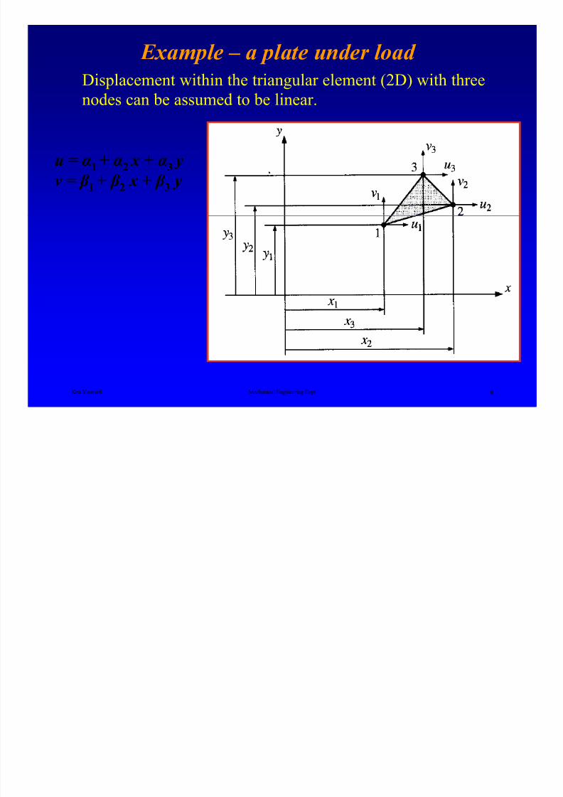
Example – a plate under load
Displacement within the triangular element (2D) with threenodes can be assumed to be linear.
u = α1 + α2 x + α3 y
v = β 1 + β 2 x + β 3 y
Ken Youssefi Mechanical Engineering Dept 9
8/4/2019 Plate Anlaysis
http://slidepdf.com/reader/full/plate-anlaysis 10/96
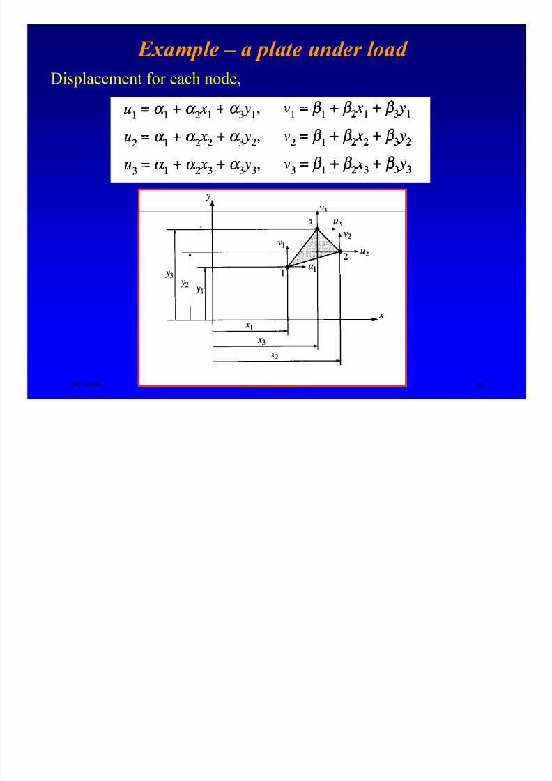
Example – a plate under load
Displacement for each node,
Ken Youssefi Mechanical Engineering Dept 10

8/4/2019 Plate Anlaysis
http://slidepdf.com/reader/full/plate-anlaysis 11/96
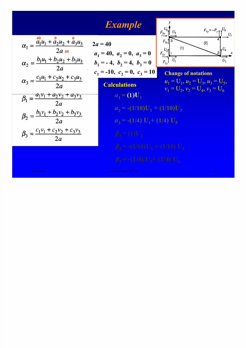
Example – a plate under load
Solve the equations simultaneously for α and β ,
Ken Youssefi Mechanical Engineering Dept 11

8/4/2019 Plate Anlaysis
http://slidepdf.com/reader/full/plate-anlaysis 12/96
Example – a plate under load
Substitute x1= 0, y1= 0 (node 1), x2=10, y2= 0 (node 2) and x3= 0, y3=4
(node 3) to obtain displacements u and v for element 1
Element 1
1
(2)
(3)Evaluate the constants a, b, and c
10 4 0 0
Ken Youssefi Mechanical Engineering Dept 12
2a = 40
Calculations:
a1 = 40, a2 = 0, a3 = 0
b1 = - 4, b2 = 4, b3 = 0
c1 = -10, c2 = 0, c3 = 10
8/4/2019 Plate Anlaysis
http://slidepdf.com/reader/full/plate-anlaysis 13/96
Example
2a = 40
a1
= 40, a2
= 0, a3
= 0
b1
= - 4, b2
= 4, b3
= 0
c1
= -10, c2
= 0, c3
= 10
Calculationsu1 = U1, u2 = U3, u3 = U5,
v1 = U2, v2 = U4, v3 = U6
Change of notations
40 00
40
Ken Youssefi Mechanical Engineering Dept 13
α1 = 1
α2 = -(1/10)U1 + (1/10)U3
α3 = -(1/4) U1+ (1/4) U5
β 1 = (1)U2
β 2 = -(1/10)U2 + (1/10) U4
β 3= -(1/4) U2+ (1/4) U6
8/4/2019 Plate Anlaysis
http://slidepdf.com/reader/full/plate-anlaysis 14/96
Example
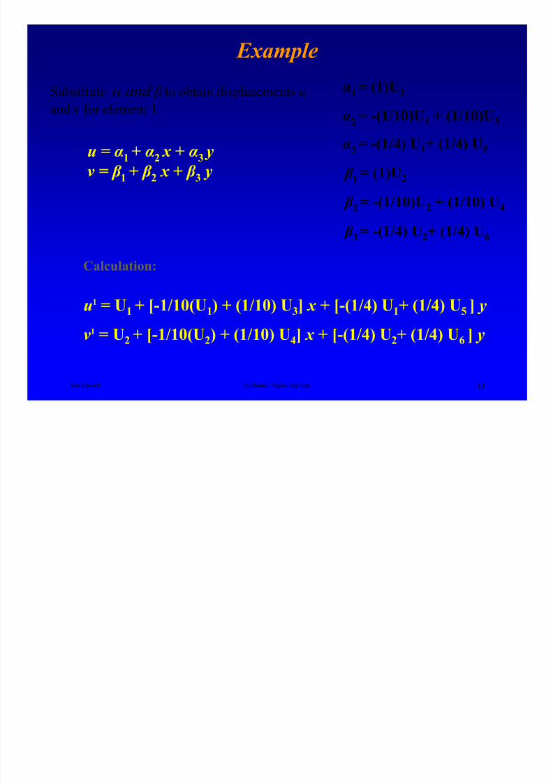
u = α1 + α2 x + α3 yv = β 1 + β 2 x + β 3 y
Substitute α and β to obtain displacements u
and v for element 1.
α1 = (1)U1
α2
= -(1/10)U1 + (1/10)U3
α3 = -(1/4) U1+ (1/4) U5
β 1= (1)U2
β 2 = -(1/10)U2 + (1/10) U4
Ken Youssefi Mechanical Engineering Dept 14
u1 = U1 + [-1/10(U1) + (1/10) U3] x + [-(1/4) U1+ (1/4) U5 ] y
v1 = U2 + [-1/10(U2) + (1/10) U4] x + [-(1/4) U2+ (1/4) U6 ] y
Calculation:
β 3 = -(1/4) U2+ (1/4) U6
8/4/2019 Plate Anlaysis
http://slidepdf.com/reader/full/plate-anlaysis 15/96
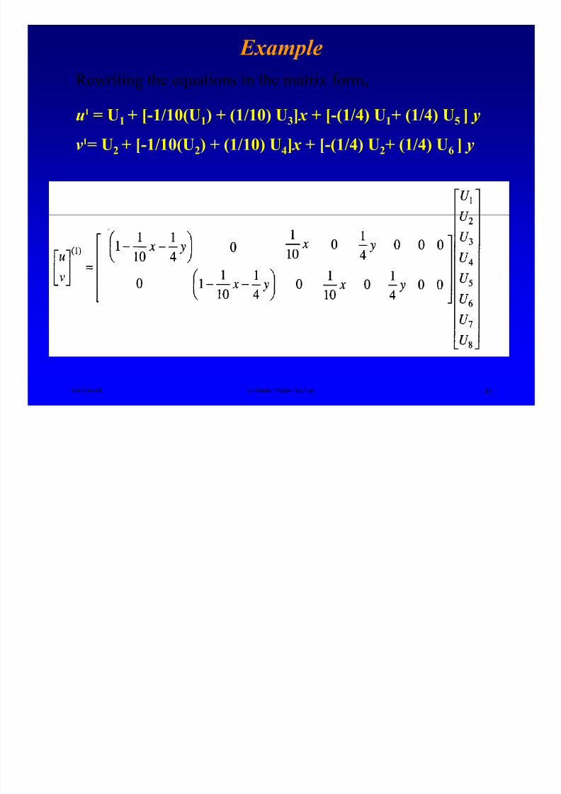
Example
Rewriting the equations in the matrix form,
u1 = U1 + [-1/10(U1) + (1/10) U3] x + [-(1/4) U1+ (1/4) U5 ] y
v1= U2
+ [-1/10(U2) + (1/10) U
4] x + [-(1/4) U
2+ (1/4) U
6] y
Ken Youssefi Mechanical Engineering Dept 15

8/4/2019 Plate Anlaysis
http://slidepdf.com/reader/full/plate-anlaysis 16/96
Example
Similarly the displacements within
element 2 can be expressed as,
Ken Youssefi Mechanical Engineering Dept 16
8/4/2019 Plate Anlaysis
http://slidepdf.com/reader/full/plate-anlaysis 17/96
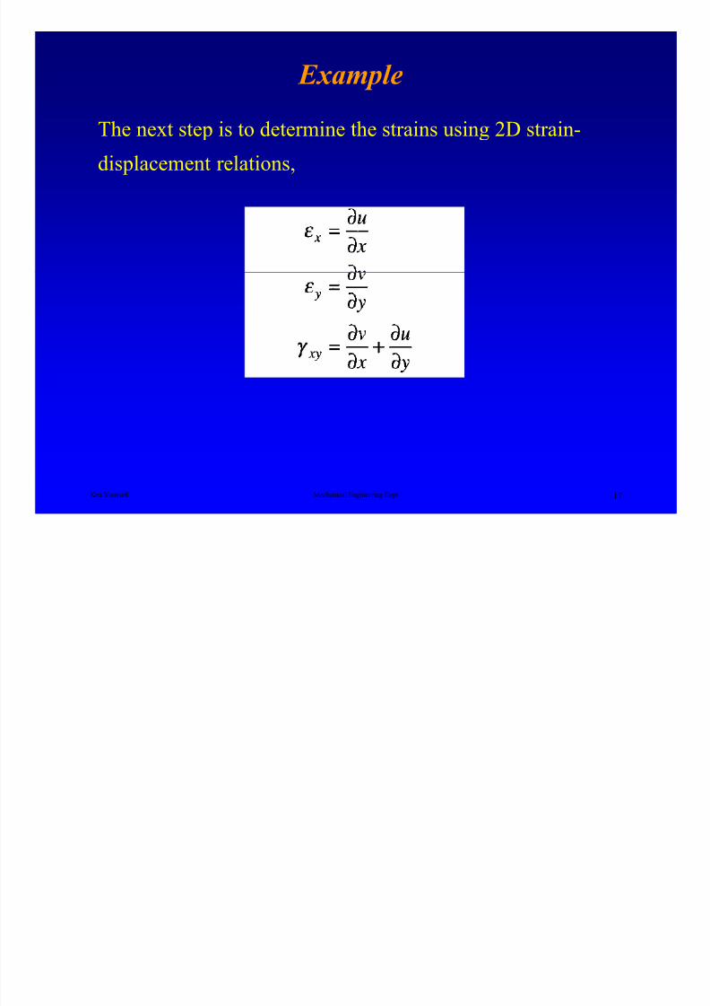
Example
The next step is to determine the strains using 2D strain-
displacement relations,
Ken Youssefi Mechanical Engineering Dept 17
8/4/2019 Plate Anlaysis
http://slidepdf.com/reader/full/plate-anlaysis 18/96
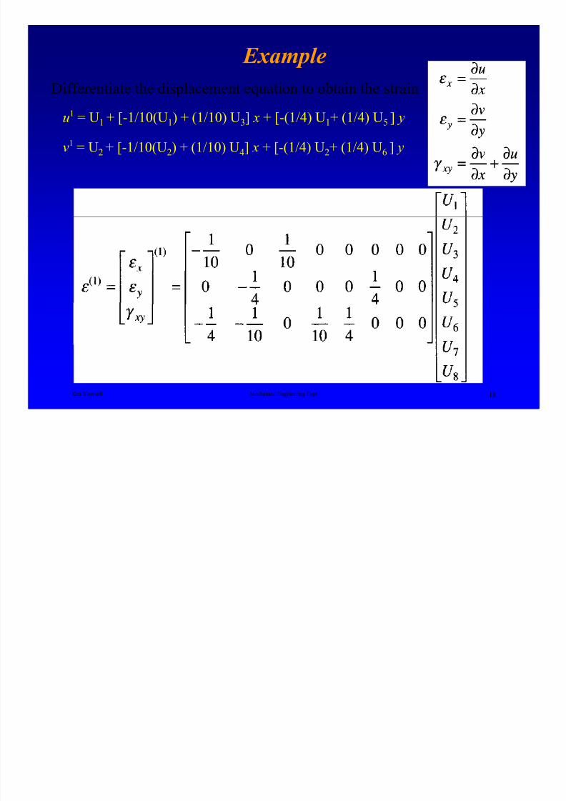
Example
Differentiate the displacement equation to obtain the strain
u1 = U1 + [-1/10(U1) + (1/10) U3] x + [-(1/4) U1+ (1/4) U5 ] y
v1 = U2+ [-1/10(U
2) + (1/10) U
4] x + [-(1/4) U
2+ (1/4) U
6] y
Ken Youssefi Mechanical Engineering Dept 18

8/4/2019 Plate Anlaysis
http://slidepdf.com/reader/full/plate-anlaysis 19/96
Example
Element 2
Ken Youssefi Mechanical Engineering Dept 19
8/4/2019 Plate Anlaysis
http://slidepdf.com/reader/full/plate-anlaysis 20/96
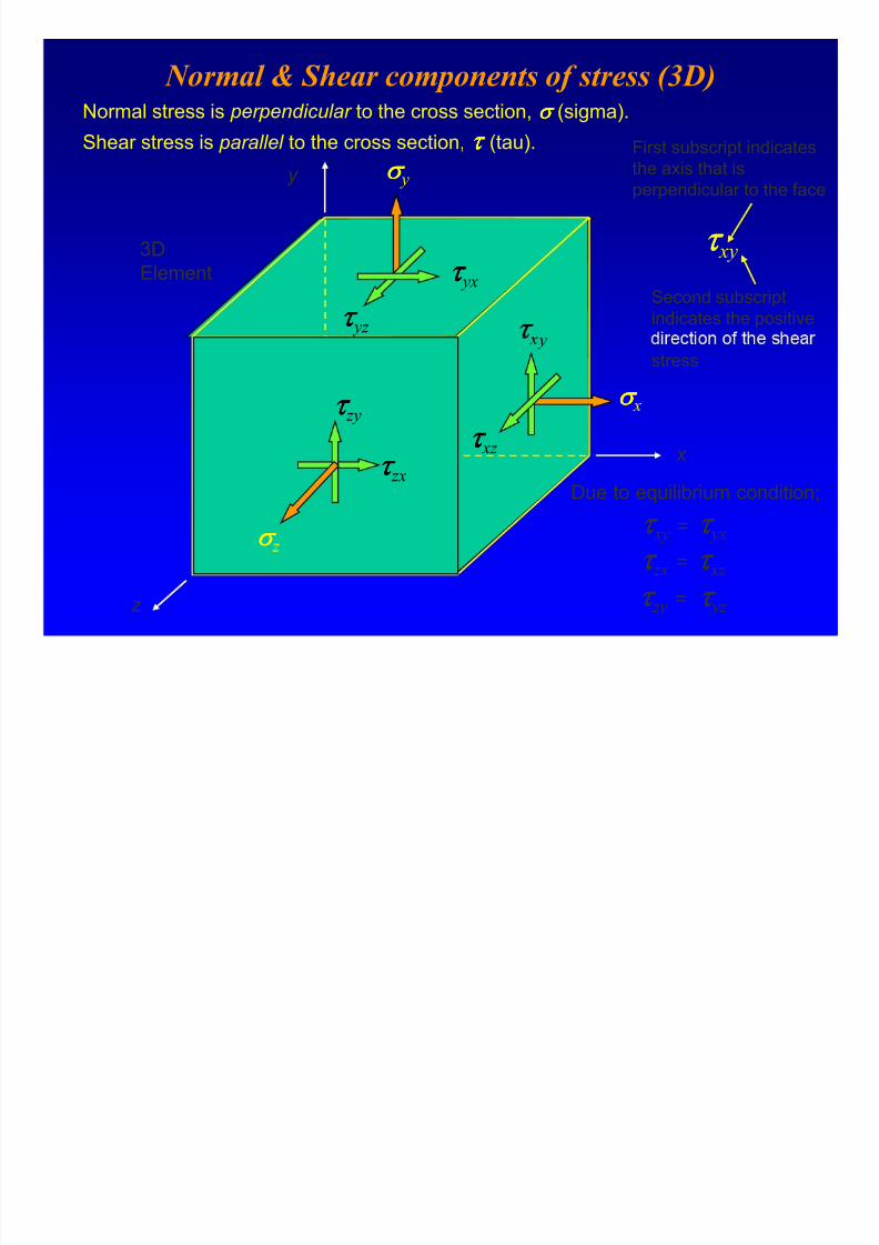
Normal & Shear components of stress (3D)Normal stress is perpendicular to the cross section, σ σσ σ (sigma).
Shear stress is parallel to the cross section, τ ττ τ (tau).
3DElement
y σ σσ σ y
τ ττ τ yz
τ ττ τ yxSecond subscript
indicates the positive
τ ττ τ xy
First subscript indicates
the axis that is
perpendicular to the face
x
z
y
σ σσ σ x
τ ττ τ xz
σ σσ σ z
τ ττ τ zx
τ ττ τ zy
stress
Due to equilibrium condition;
τ ττ τ xy = τ ττ τ yx
τ ττ τ zy = τ ττ τ yz
τ ττ τ zx = τ ττ τ xz
8/4/2019 Plate Anlaysis
http://slidepdf.com/reader/full/plate-anlaysis 21/96
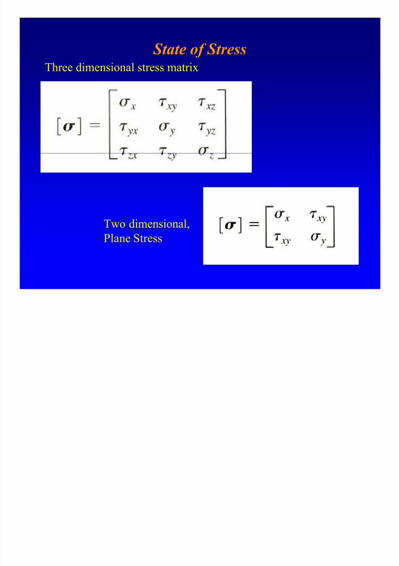
State of StressThree dimensional stress matrix
Two dimensional,
Plane Stress
8/4/2019 Plate Anlaysis
http://slidepdf.com/reader/full/plate-anlaysis 22/96
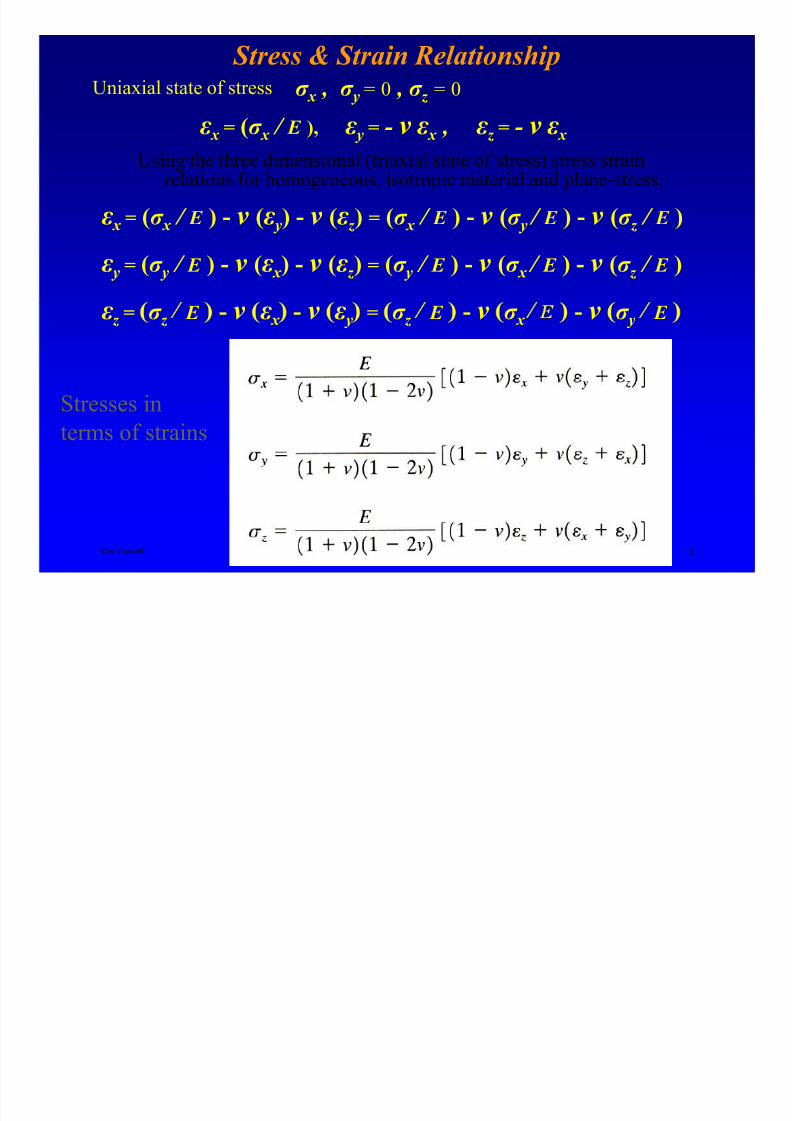
Stress & Strain Relationship
Using the three dimensional (triaxial state of stress) stress strainrelations for homogeneous, isotropic material and plane-stress,
ε x = (σ x / E ) - ν (ε y) - ν (ε z ) = (σ x / E ) - ν (σ y / E ) - ν (σ z / E )
ε y = (σ y / E ) - ν (ε x ) - ν (ε z ) = (σ y / E ) - ν (σ x / E ) - ν (σ z / E )
Uniaxial state of stress
ε x = (σ x / E ), ε y = - ν ε x , ε z = - ν ε x
σ x , σ y = 0 , σ z = 0
Ken Youssefi Mechanical Engineering Dept 22
ε z
= σ z
E - ν ε x
- ν ε y
= σ z
E - ν σ x
- ν σ y
E
Stresses in
terms of strains
8/4/2019 Plate Anlaysis
http://slidepdf.com/reader/full/plate-anlaysis 23/96
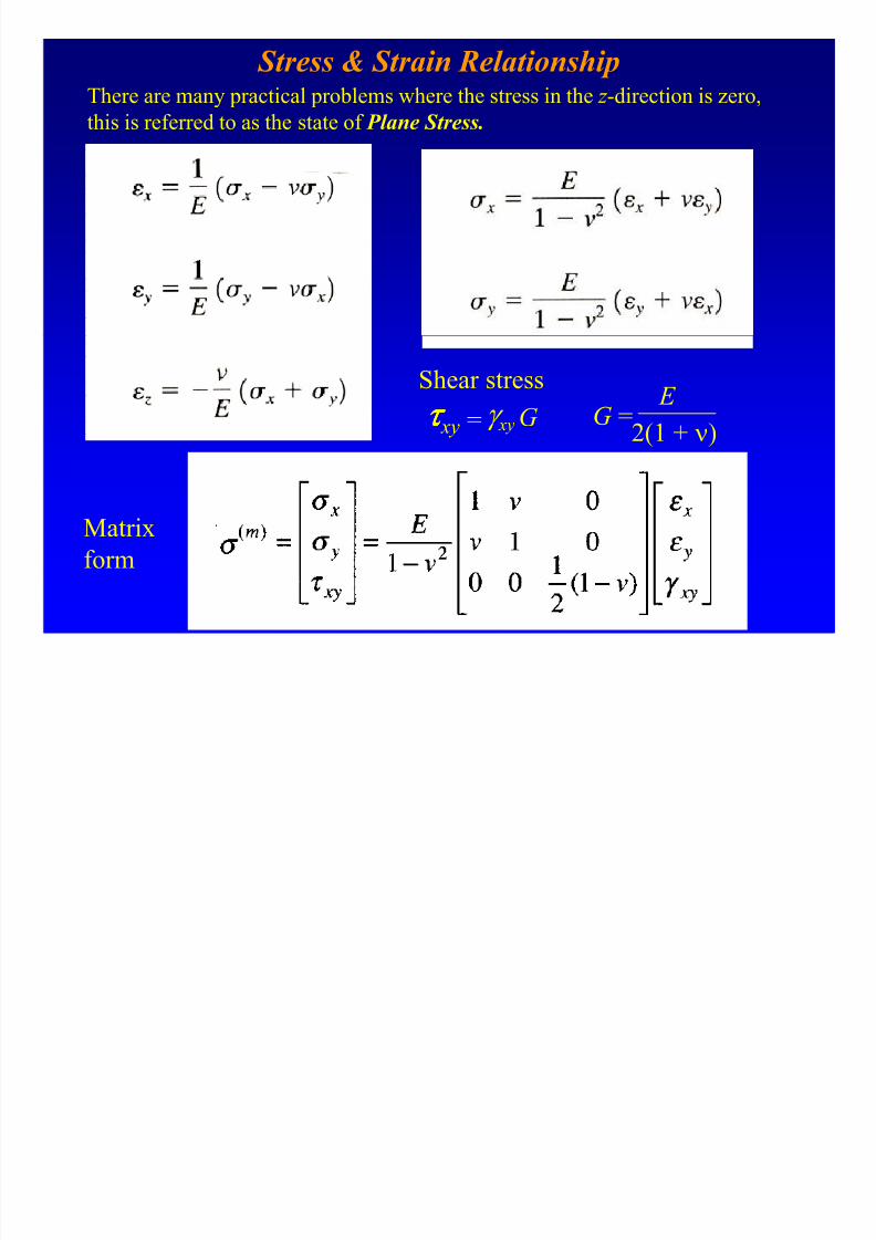
Stress & Strain RelationshipThere are many practical problems where the stress in the z -direction is zero,
this is referred to as the state of Plane Stress.
G = E
2(1 + ν)= γ xy Gτ ττ τ xy
Shear stress
Matrix
form
8/4/2019 Plate Anlaysis
http://slidepdf.com/reader/full/plate-anlaysis 24/96
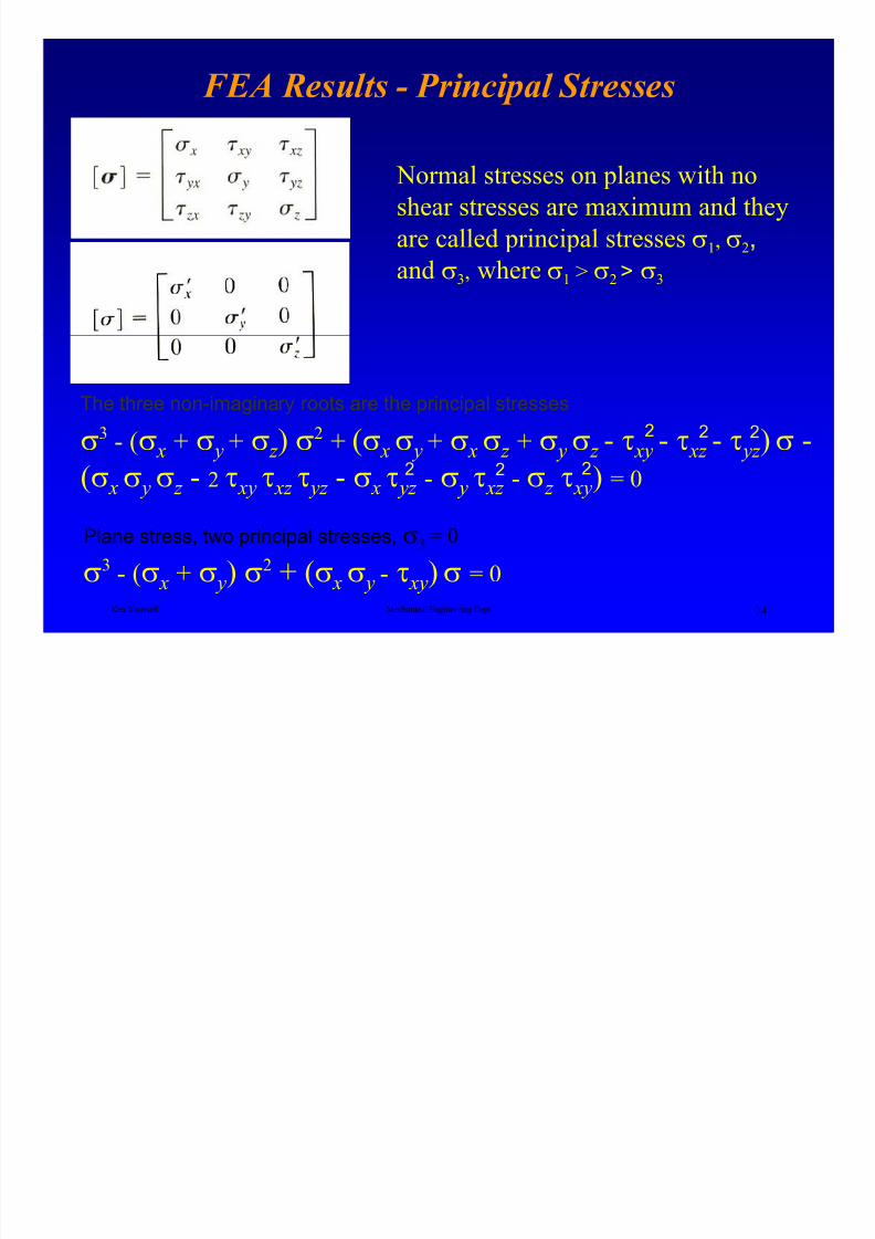
FEA Results - Principal Stresses
Normal stresses on planes with no
shear stresses are maximum and they
are called principal stresses σ1, σ2,and σ3, where σ1 > σ2 > σ3
Ken Youssefi Mechanical Engineering Dept 24
The three non-imaginary roots are the principal stresses
2
2
σ3 - (σ x + σ y + σ z ) σ
2 + (σ x σ y + σ x σ z + σ y σ z - τ xy - τ xz - τ yz )σ -
(σ x σ y σ z - 2 τ xy τ xz τ yz - σ x τ yz - σ y τ xz - σ z τ xy) = 02
22
2
σ3 - (σ x + σ y) σ
2 + (σ x σ y - τ xy)σ = 0
Plane stress, two principal stresses, σ3 = 0
8/4/2019 Plate Anlaysis
http://slidepdf.com/reader/full/plate-anlaysis 25/96
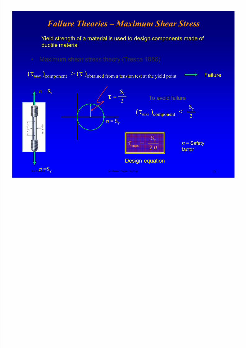
Failure Theories – Maximum Shear Stress
• Maximum shear stress theory (Tresca 1886)
Yield strength of a material is used to design components made of
ductile material
Sσ = S
(τmax )component > (τ )obtained from a tension test at the yield point Failure
Ken Youssefi Mechanical Engineering Dept 25
σ = Sy
τ2
=
σ =Sy
(τmax )component <Sy
2
To avoid failure
τmax =Sy
2 nn = Safety
factor
Design equation
8/4/2019 Plate Anlaysis
http://slidepdf.com/reader/full/plate-anlaysis 26/96
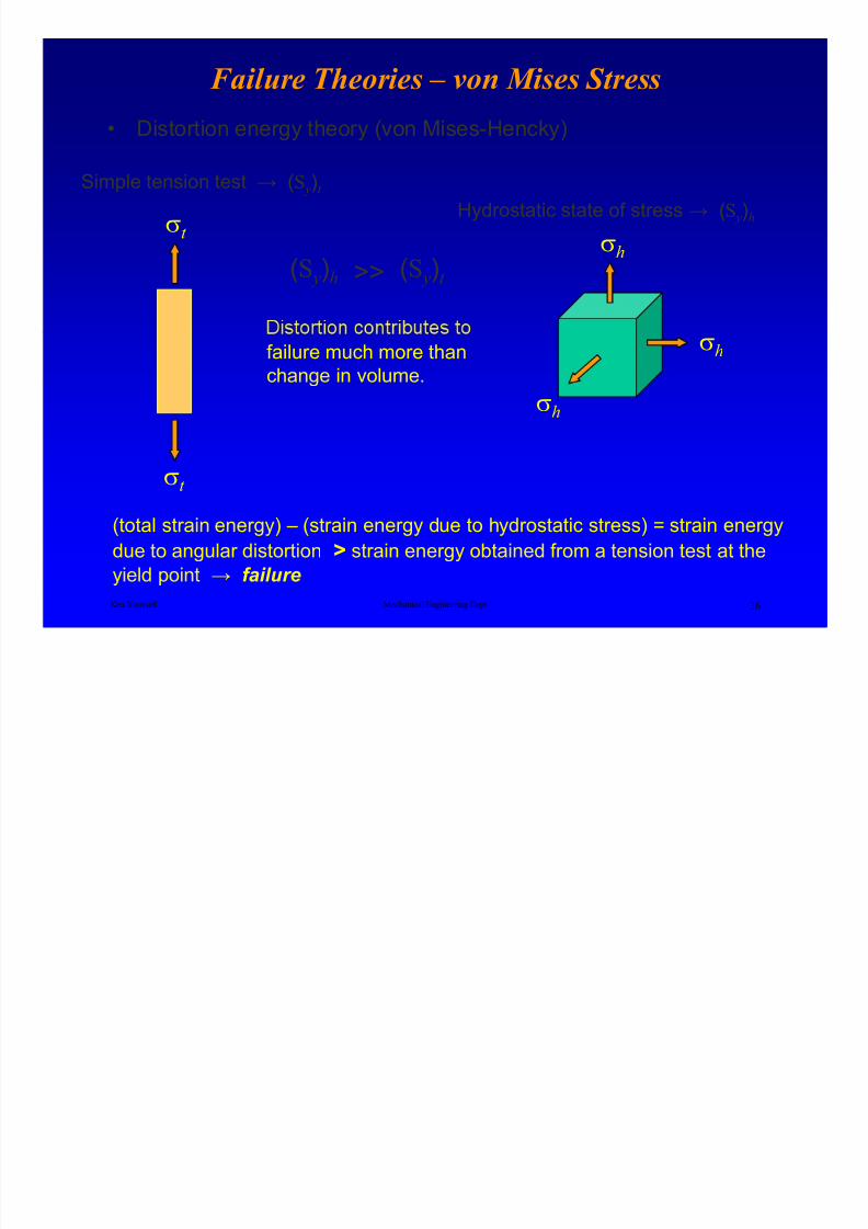
Failure Theories – von Mises Stress
• Distortion energy theory (von Mises-Hencky)
σt
Simple tension test → (S y)t
(S y)t (S y)h >>
Hydrostatic state of stress → (S y)h
σh
Ken Youssefi Mechanical Engineering Dept 26
σt
failure much more thanchange in volume.
(total strain energy) – (strain energy due to hydrostatic stress) = strain energy
due to angular distortion > strain energy obtained from a tension test at the
yield point → failure
σh
σh
8/4/2019 Plate Anlaysis
http://slidepdf.com/reader/full/plate-anlaysis 27/96
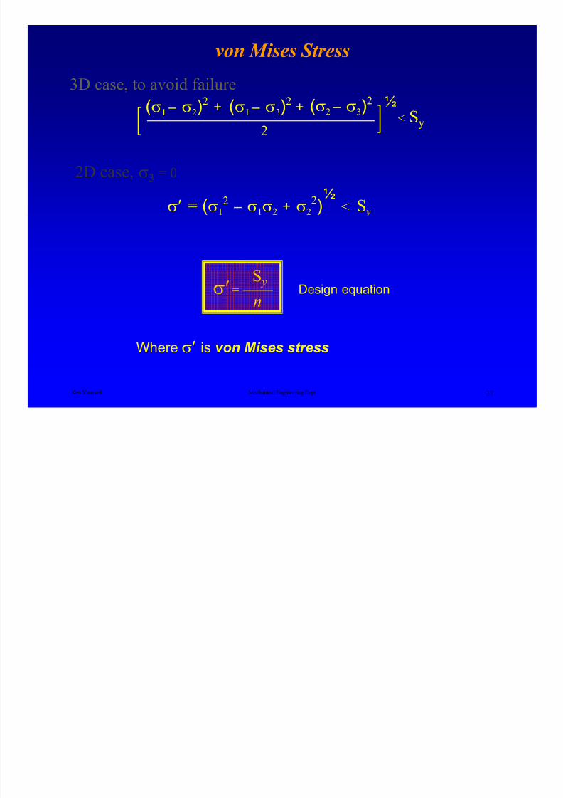
von Mises Stress
½
2D case, σ3 = 0
σ′ = (σ12 – σ1σ2 + σ2
2) < S
(σ1 – σ2)2
+ (σ1 – σ3)2
+ (σ2 – σ3)2
2
½< Sy
3D case, to avoid failure
Ken Youssefi Mechanical Engineering Dept 27
Where σ′ is von Mises stress
σ′ =S y
n
Design equation
8/4/2019 Plate Anlaysis
http://slidepdf.com/reader/full/plate-anlaysis 28/96
Formulation of the Finite Element Method
• The classical finite element analysis code (h version)The system equations for solid and structural
mechanics problems are derived using the principle of
virtual displacement and work (Bathe, 1982).• The method of weighted residuals (Galerkin Method)
weighted residuals are used as one method of finite
Ken Youssefi Mechanical Engineering Dept 28
element formulation starting from the governing
differential equation.
• Potential Energy and Equilibrium; The Rayleigh-Ritz
Method
Involves the construction of assumed displacement field.
Uses the total potential energy for an elastic body

8/4/2019 Plate Anlaysis
http://slidepdf.com/reader/full/plate-anlaysis 29/96
Formulation of the Finite Element Method
Ken Youssefi Mechanical Engineering Dept 29
f B – Body forces (forces distributed over the volume of the body:
(gravitational forces, inertia, or magnetic)
f S – surface forces (pressure of one body on another, or hydrostatic
pressure)
f i – Concentrated external forces

8/4/2019 Plate Anlaysis
http://slidepdf.com/reader/full/plate-anlaysis 30/96
Formulation of the Finite Element Method
Let’s denote the displacements of any point ( x, y, z ) of the objectfrom the unloaded configuration as UT
U T = [U ( x, y, z ) V ( x, y, z ) W ( x, y, z )]
The displacement U causes the strains
ε T = [ε x ε ε z γ x γ z γ zx ]
Ken Youssefi Mechanical Engineering Dept 30
and the corresponding stresses
The goal is to calculate displacement, strains, and stresses from
the given external forces.
σ T = [σ x σ y σ z τ xy τ yz τ zx ]
8/4/2019 Plate Anlaysis
http://slidepdf.com/reader/full/plate-anlaysis 31/96
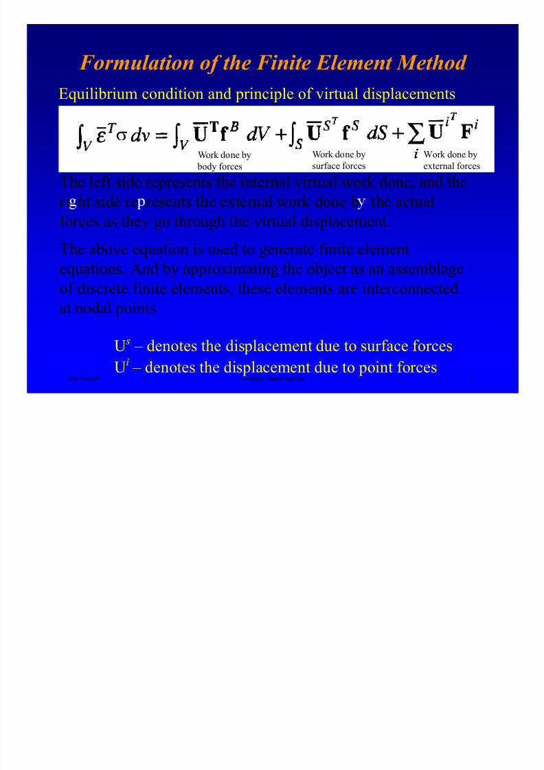
Formulation of the Finite Element Method
Equilibrium condition and principle of virtual displacements
The left side represents the internal virtual work done, and the
ri ht side re resents the external work done b the actual
σ
Work done by body forces
Work done bysurface forces
Work done byexternal forces
Ken Youssefi Mechanical Engineering Dept 31
forces as they go through the virtual displacement.The above equation is used to generate finite element
equations. And by approximating the object as an assemblage
of discrete finite elements, these elements are interconnected
at nodal points
U s – denotes the displacement due to surface forces
Ui
– denotes the displacement due to point forces
8/4/2019 Plate Anlaysis
http://slidepdf.com/reader/full/plate-anlaysis 32/96
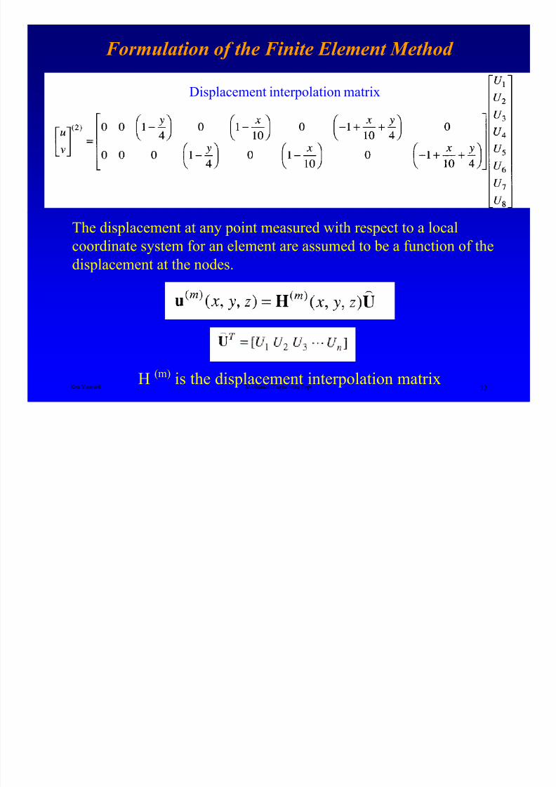
Formulation of the Finite Element Method
Displacement interpolation matrix
Ken Youssefi Mechanical Engineering Dept 32
The displacement at any point measured with respect to a localcoordinate system for an element are assumed to be a function of the
displacement at the nodes.
H(m)
is the displacement interpolation matrix
8/4/2019 Plate Anlaysis
http://slidepdf.com/reader/full/plate-anlaysis 33/96
Formulation of the Finite Element Method
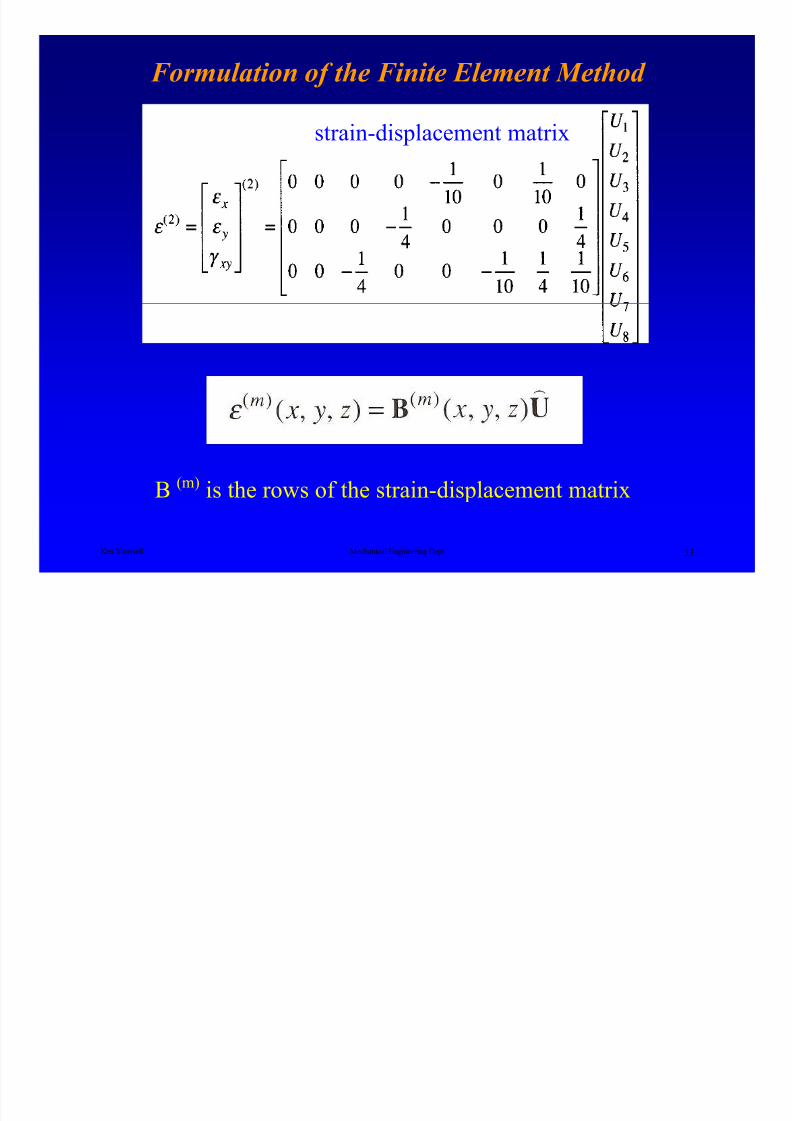
strain-displacement matrix
Ken Youssefi Mechanical Engineering Dept 33
B (m) is the rows of the strain-displacement matrix
8/4/2019 Plate Anlaysis
http://slidepdf.com/reader/full/plate-anlaysis 34/96
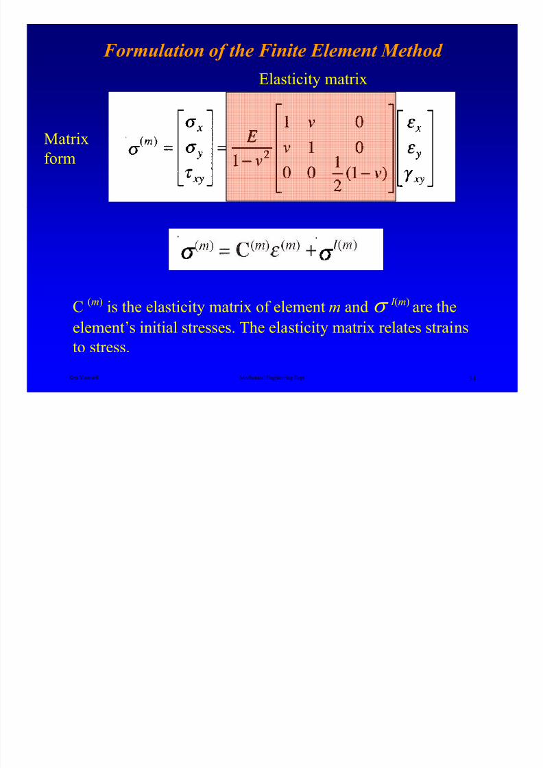
Matrix
form
Formulation of the Finite Element Method
Elasticity matrix
Ken Youssefi Mechanical Engineering Dept 34
C (m) is the elasticity matrix of element m and σ I (m) are the
element’s initial stresses. The elasticity matrix relates strains
to stress.
8/4/2019 Plate Anlaysis
http://slidepdf.com/reader/full/plate-anlaysis 35/96
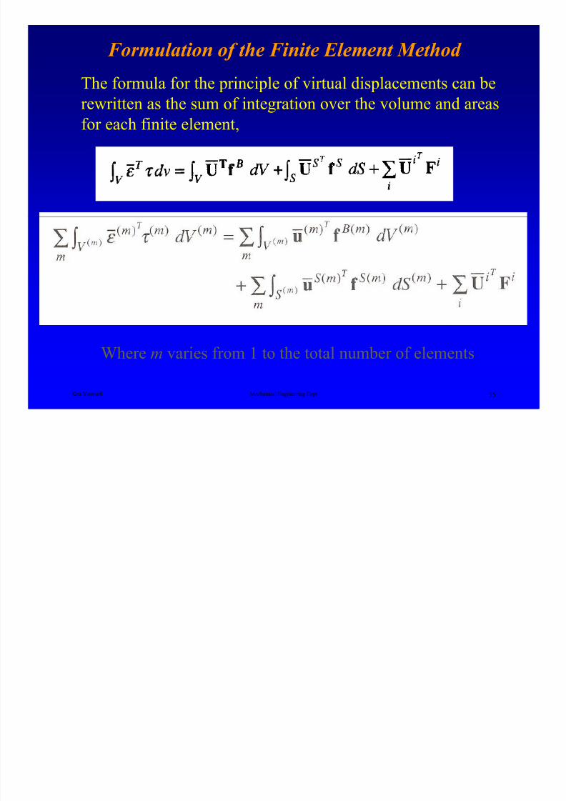
Formulation of the Finite Element Method
The formula for the principle of virtual displacements can berewritten as the sum of integration over the volume and areas
for each finite element,
Ken Youssefi Mechanical Engineering Dept 35
Where m varies from 1 to the total number of elements
8/4/2019 Plate Anlaysis
http://slidepdf.com/reader/full/plate-anlaysis 36/96
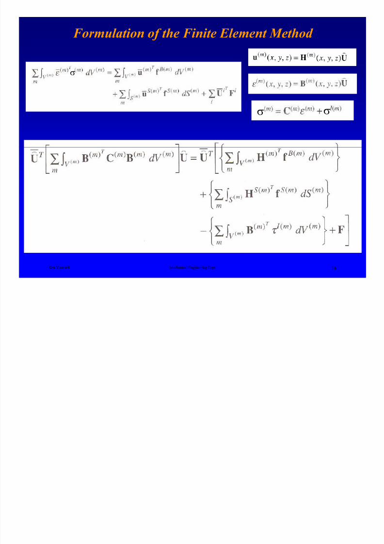
Formulation of the Finite Element Method
σ
σ σ
Ken Youssefi Mechanical Engineering Dept 36

8/4/2019 Plate Anlaysis
http://slidepdf.com/reader/full/plate-anlaysis 37/96
Formulation of the Finite Element Method
The equilibrium equation can be expressed using matrix
notations for m elements.
where
Ken Youssefi Mechanical Engineering Dept 37
B
(m)
Represents the rows of the strain displacement matrixC(m) Elasticity matrix of element m
H(m) Displacement interpolation matrix
U Vector of the three global displacement
components at all nodesF Vector of the external concentrated forces
applied to the nodes
F l ti f th Fi it El t M th d
8/4/2019 Plate Anlaysis
http://slidepdf.com/reader/full/plate-anlaysis 38/96
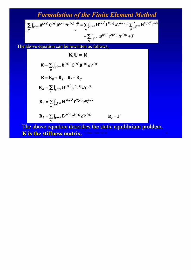
Formulation of the Finite Element Method
The above equation can be rewritten as follows,
Ken Youssefi Mechanical Engineering Dept 38
The above equation describes the static equilibrium problem.
K is the stiffness matrix.

8/4/2019 Plate Anlaysis
http://slidepdf.com/reader/full/plate-anlaysis 39/96
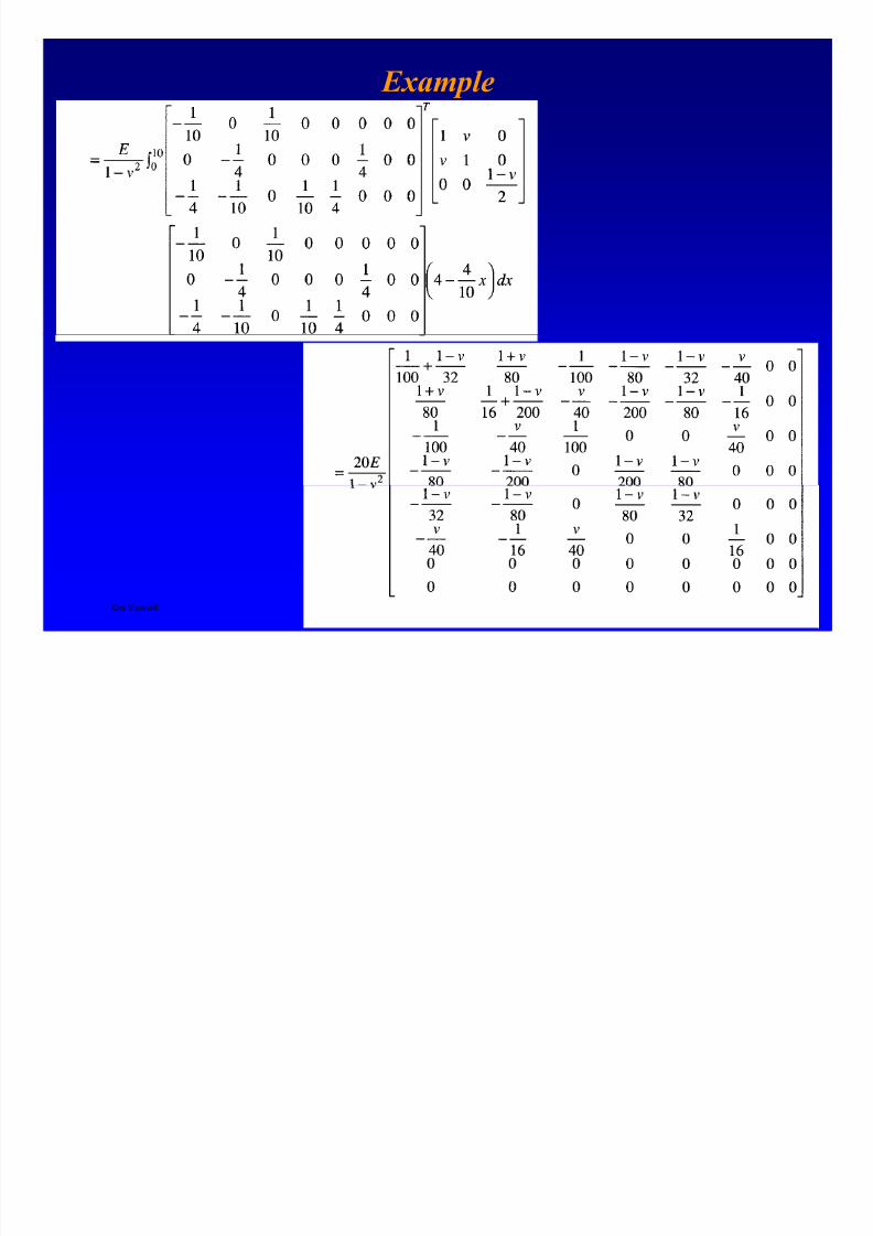
Continuing the example
C(m) - Elasticity matrix of element m
B(m) - Represents the rows of the strain
displacement matrix
Ken Youssefi Mechanical Engineering Dept 39
dx x
y
y = 4 - x4
10dA = y dx
8/4/2019 Plate Anlaysis
http://slidepdf.com/reader/full/plate-anlaysis 40/96
Example
Ken Youssefi Mechanical Engineering Dept 40
8/4/2019 Plate Anlaysis
http://slidepdf.com/reader/full/plate-anlaysis 41/96
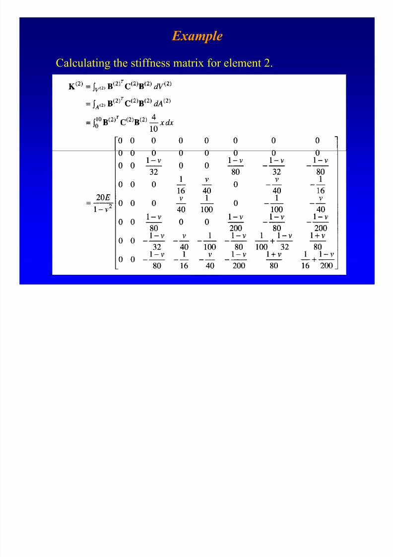
Example
Calculating the stiffness matrix for element 2.
Ken Youssefi Mechanical Engineering Dept 41
8/4/2019 Plate Anlaysis
http://slidepdf.com/reader/full/plate-anlaysis 42/96
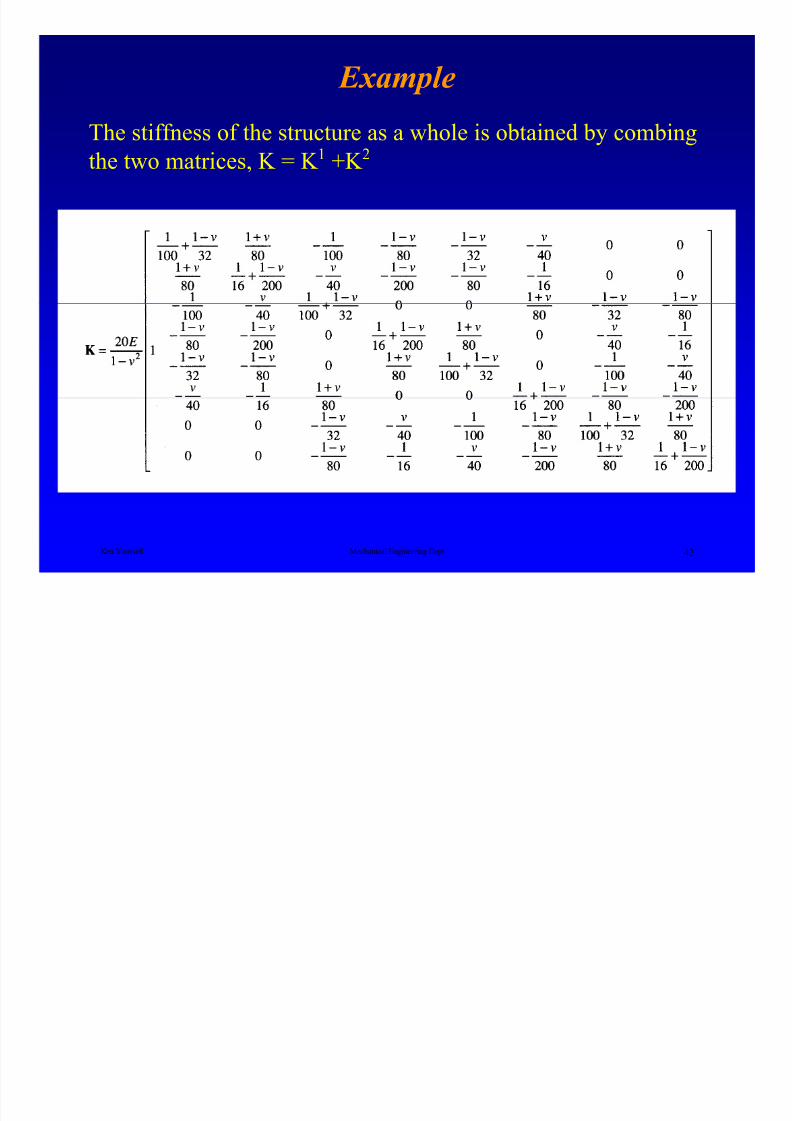
Example
The stiffness of the structure as a whole is obtained by combing
the two matrices, K = K 1 +K 2
Ken Youssefi Mechanical Engineering Dept 42
Example
8/4/2019 Plate Anlaysis
http://slidepdf.com/reader/full/plate-anlaysis 43/96
Example
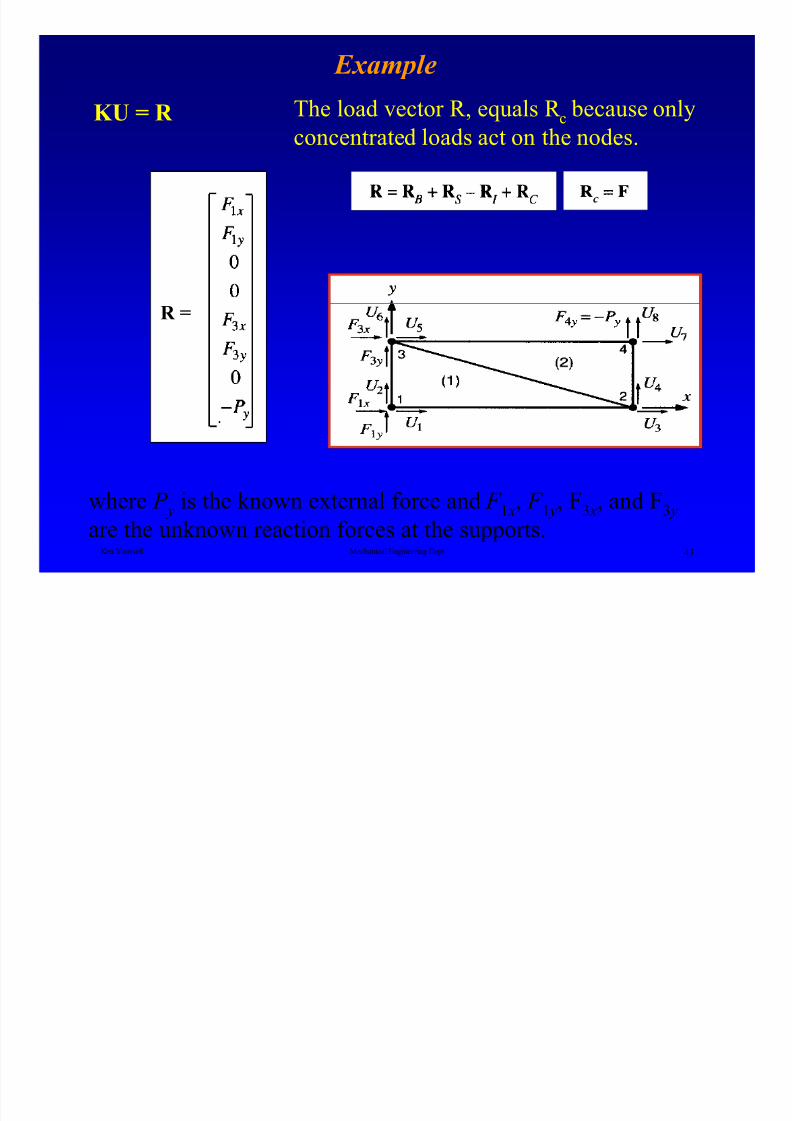
KU = R The load vector R, equals R c because onlyconcentrated loads act on the nodes.
Ken Youssefi Mechanical Engineering Dept 43
where P y is the known external force and F 1 x, F 1 y, F3 x, and F3 y
are the unknown reaction forces at the supports.
R =
Example
8/4/2019 Plate Anlaysis
http://slidepdf.com/reader/full/plate-anlaysis 44/96
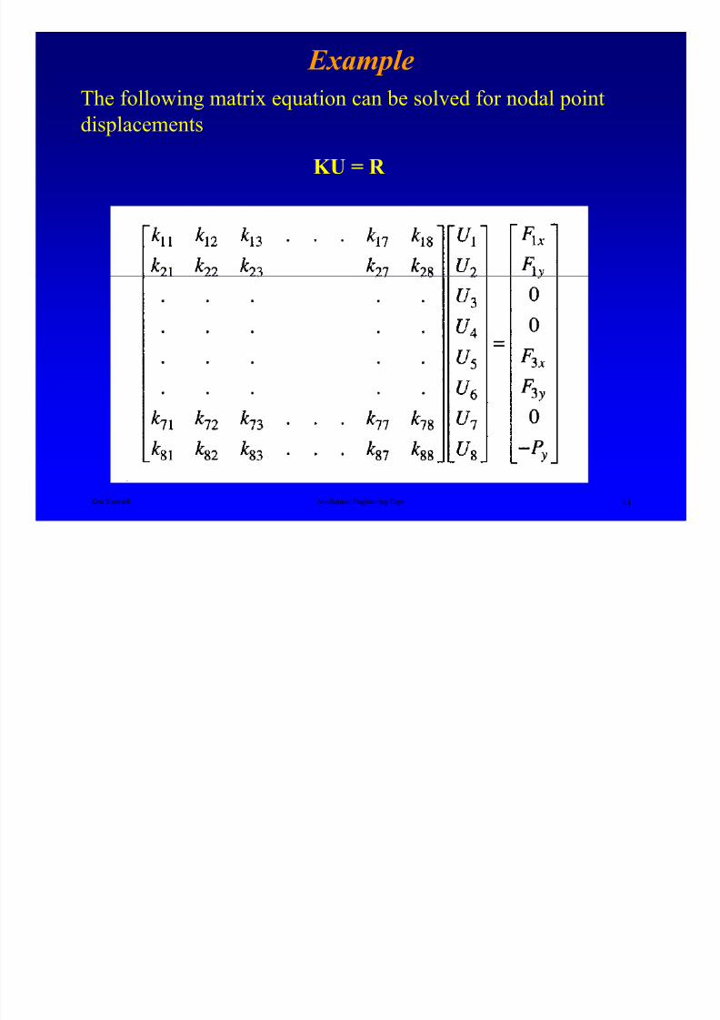
Example
The following matrix equation can be solved for nodal pointdisplacements
KU = R
Ken Youssefi Mechanical Engineering Dept 44
Example

8/4/2019 Plate Anlaysis
http://slidepdf.com/reader/full/plate-anlaysis 45/96
ExampleThe solution can be obtained by applying the boundary conditions
Ken Youssefi Mechanical Engineering Dept 45
No deflectionat the supports
Example

8/4/2019 Plate Anlaysis
http://slidepdf.com/reader/full/plate-anlaysis 46/96
Example
The equation can be divided into two parts,
Ken Youssefi Mechanical Engineering Dept 46
The first equation can be solved for the unknown nodal displacements,
U 3, U 4, U 7, and U 8. And substituting these values into the secondequation to obtain unknown reaction forces, F 1 x, F 1 y, F3 x, and F3 y
Once the nodal displacements have been obtained, the strains
and stresses can be calculated.
8/4/2019 Plate Anlaysis
http://slidepdf.com/reader/full/plate-anlaysis 47/96
Finite Element Analysis
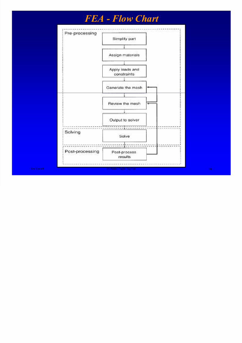
FEA requires three steps
FEA is a mathematical representation of a physical system
and the solution of that mathematical representation
Ken Youssefi Mechanical Engineering Dept 47
• Pre-Processing• Solving Matrix (solver)
• Post-Processing
FEA P P i

8/4/2019 Plate Anlaysis
http://slidepdf.com/reader/full/plate-anlaysis 48/96
FEA Pre-Processing
Mesh
Mesh is your way of communicating geometry to
the solver, the accuracy of the solution is primarily
dependent on the quality of the mesh.
The better the mesh looks, the more accurate the
Ken Youssefi Mechanical Engineering Dept 48
solution is.A good-looking mesh should have well-shaped
elements (proportional), and the transition between
densities should be smooth and gradual withoutskinny, distorted elements.
FEA Pre-Processing - meshing
8/4/2019 Plate Anlaysis
http://slidepdf.com/reader/full/plate-anlaysis 49/96
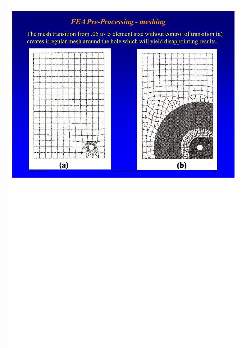
FEA Pre-Processing - meshing
The mesh transition from .05 to .5 element size without control of transition (a)creates irregular mesh around the hole which will yield disappointing results.
Ken Youssefi Mechanical Engineering Dept 49
FEA Pre Processing
8/4/2019 Plate Anlaysis
http://slidepdf.com/reader/full/plate-anlaysis 50/96
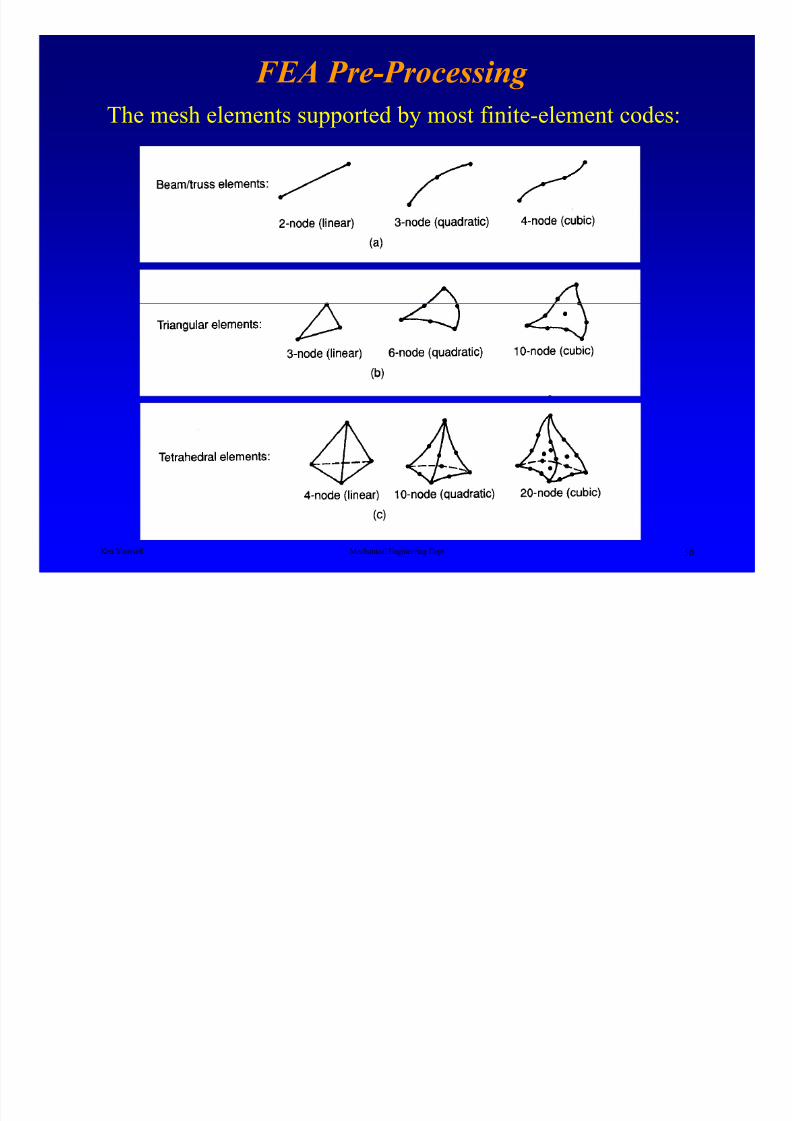
FEA Pre-Processing
The mesh elements supported by most finite-element codes:
Ken Youssefi Mechanical Engineering Dept 50
FEA P P i El t
8/4/2019 Plate Anlaysis
http://slidepdf.com/reader/full/plate-anlaysis 51/96
FEA Pre-Processing – Elements
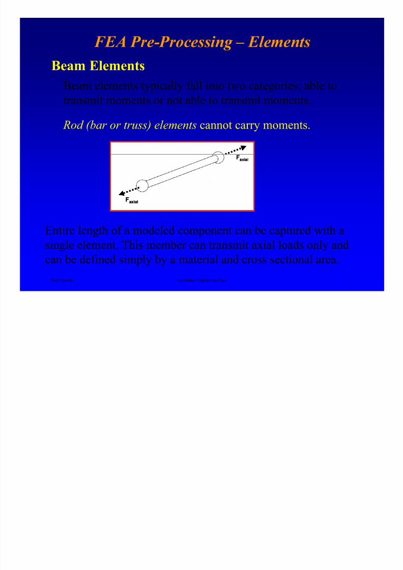
Beam Elements
Beam elements typically fall into two categories; able to
transmit moments or not able to transmit moments.
Rod (bar or truss) elements cannot carry moments.
Ken Youssefi Mechanical Engineering Dept 51
Entire length of a modeled component can be captured with a
single element. This member can transmit axial loads only and
can be defined simply by a material and cross sectional area.
FEA P P i El
8/4/2019 Plate Anlaysis
http://slidepdf.com/reader/full/plate-anlaysis 52/96
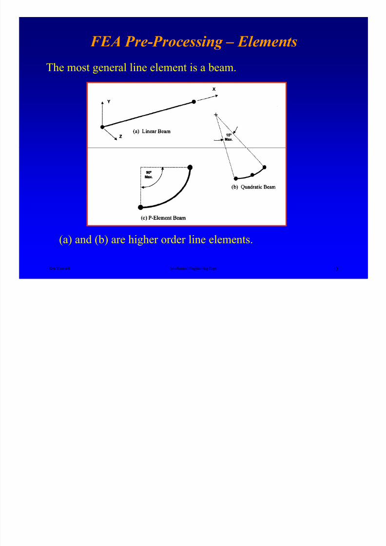
FEA Pre-Processing – Elements
The most general line element is a beam.
Ken Youssefi Mechanical Engineering Dept 52
(a) and (b) are higher order line elements.
FEA P P i El t
8/4/2019 Plate Anlaysis
http://slidepdf.com/reader/full/plate-anlaysis 53/96
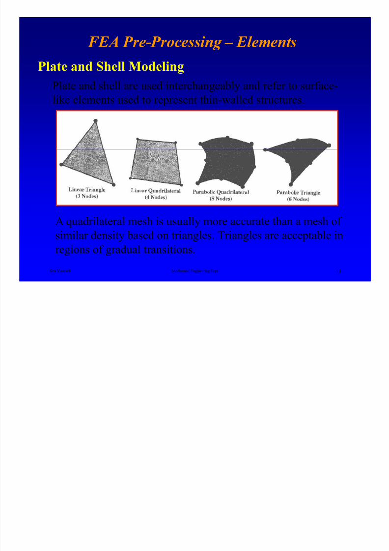
FEA Pre-Processing – Elements
Plate and Shell Modeling
Plate and shell are used interchangeably and refer to surface-
like elements used to represent thin-walled structures.
Ken Youssefi Mechanical Engineering Dept 53
A quadrilateral mesh is usually more accurate than a mesh of
similar density based on triangles. Triangles are acceptable in
regions of gradual transitions.
FEA Pre-Processing – Elements
8/4/2019 Plate Anlaysis
http://slidepdf.com/reader/full/plate-anlaysis 54/96
FEA Pre Processing Elements
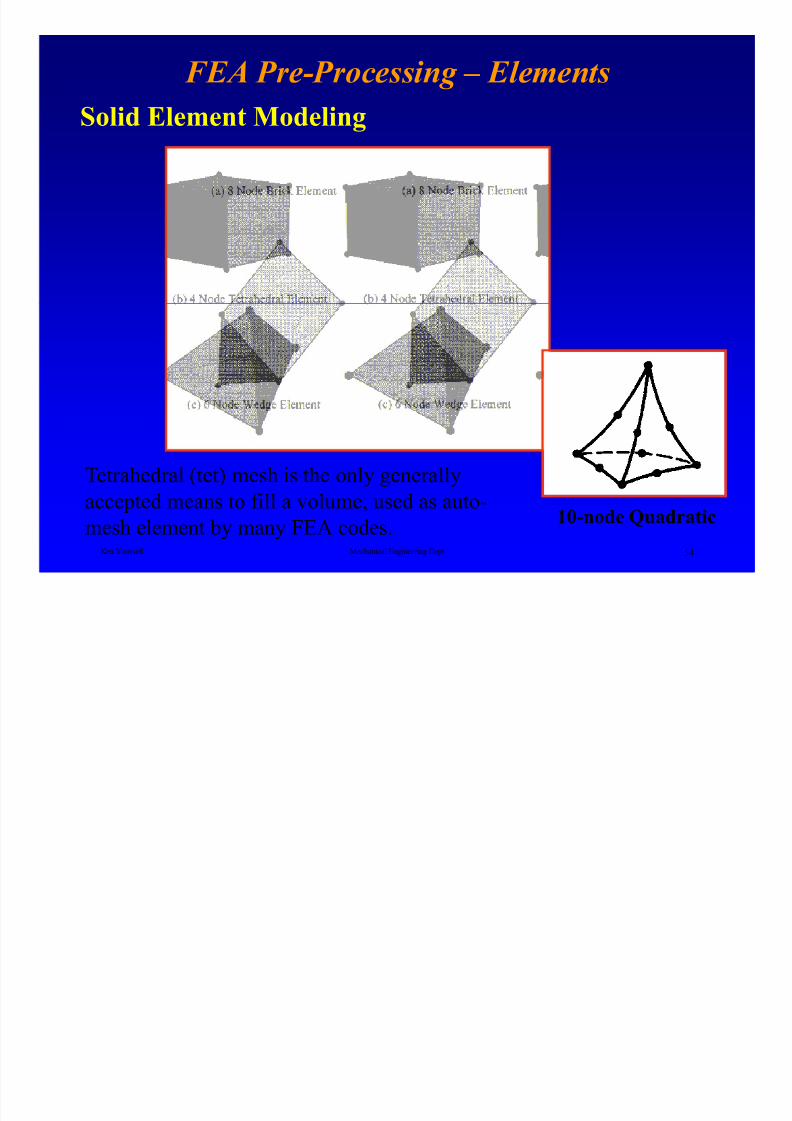
Solid Element Modeling
Ken Youssefi Mechanical Engineering Dept 54
Tetrahedral (tet) mesh is the only generally
accepted means to fill a volume, used as auto-
mesh element by many FEA codes.10-node Quadratic
CAD Modeling for FEA
8/4/2019 Plate Anlaysis
http://slidepdf.com/reader/full/plate-anlaysis 55/96
CAD Modeling for FEA
• CAD models prepared by the design group for
eventual FEA.
CAD and FEA activities should be coordinated at the early stages
of the design process to minimize the duplication of effort.
There are four situations
Ken Youssefi Mechanical Engineering Dept 55
• CAD models prepared without consideration of
FEA needs.
• CAD models unsuitable for use in analysis due to
the amount of rework required.
• Analytical geometry developed by or for analyst
for sole purpose of FEA.
CAD Modeling for FEA

8/4/2019 Plate Anlaysis
http://slidepdf.com/reader/full/plate-anlaysis 56/96
CAD Modeling for FEA
• Solid chunky parts (thick-walled, low aspect ratio)
parts mesh cleanly directly off CAD models.
• Clean geometrygeometrical features must not prevent the mesh from being created. The model should not include buried
Ken Youssefi Mechanical Engineering Dept 56
features.
• Parent-child relationships
parametric modeling allows defining features off other CAD features.
CAD Modeling for FEA

8/4/2019 Plate Anlaysis
http://slidepdf.com/reader/full/plate-anlaysis 57/96
CAD Modeling for FEA
Short edges and Sliver surfacesShort edges and sliver surfaces usually accompany each other and on
large faces can cause highly distorted elements or a failed mesh.
Ken Youssefi Mechanical Engineering Dept 57
CAD Modeling for FEA – Sliver Surfaces
8/4/2019 Plate Anlaysis
http://slidepdf.com/reader/full/plate-anlaysis 58/96
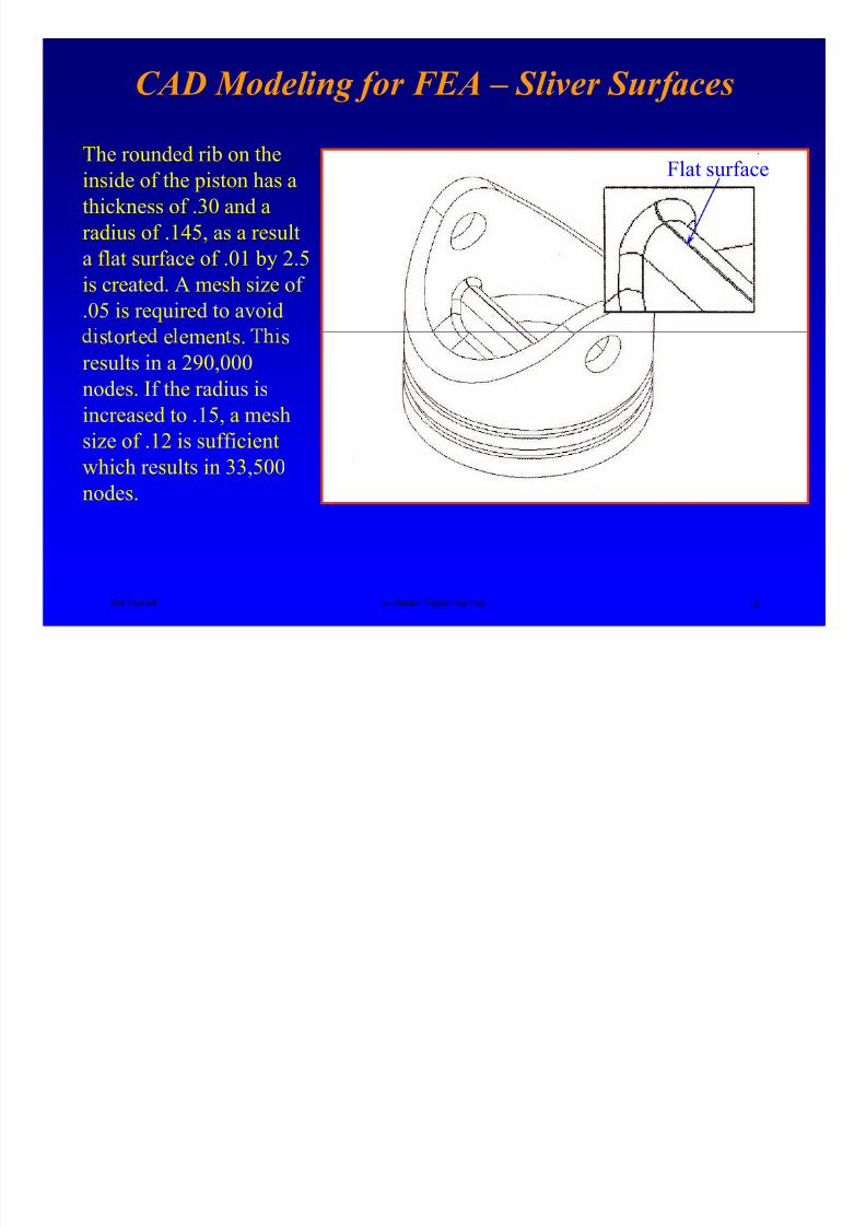
CAD Modeling for FEA Sliver Surfaces
The rounded rib on the
inside of the piston has a
thickness of .30 and a
radius of .145, as a result
a flat surface of .01 by 2.5
is created. A mesh size of
.05 is required to avoid
Flat surface
Ken Youssefi Mechanical Engineering Dept 58
s or e e emen s. s
results in a 290,000nodes. If the radius is
increased to .15, a mesh
size of .12 is sufficient
which results in 33,500
nodes.
CAD Modeling for FEA

8/4/2019 Plate Anlaysis
http://slidepdf.com/reader/full/plate-anlaysis 59/96
Sliver surface caused by
misaligned features.
Ken Youssefi Mechanical Engineering Dept 59
Fillet across shallow angle
Sliver surface caused by a slightly
undersized fillet
G id li f G t Pl i
8/4/2019 Plate Anlaysis
http://slidepdf.com/reader/full/plate-anlaysis 60/96
Guidelines for Geometry Planning
• Delay inclusion of fillets and chamfers as long as
possible.
• Try to use permanent datums as references where
possible to minimize dependencies.
Ken Youssefi Mechanical Engineering Dept 60
• vo us ng e or ra e ges as re erences or
other features (parent-child relationship)
• Never bury a feature in your model. Delete or
redefine unwanted or incorrect features.
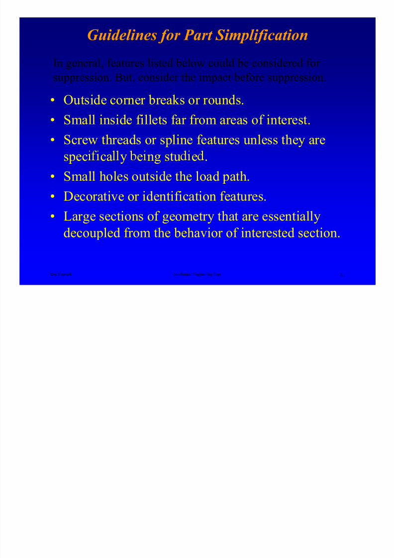
Guidelines for Part Simplification
8/4/2019 Plate Anlaysis
http://slidepdf.com/reader/full/plate-anlaysis 61/96
• Outside corner breaks or rounds.
• Small inside fillets far from areas of interest.
• Screw threads or spline features unless they are
In general, features listed below could be considered for suppression. But, consider the impact before suppression.
Ken Youssefi Mechanical Engineering Dept 61
spec ca y e ng stu e .
• Small holes outside the load path.
• Decorative or identification features.
• Large sections of geometry that are essentiallydecoupled from the behavior of interested section.
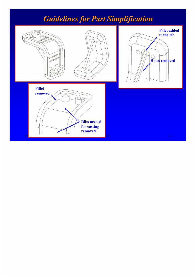
Guidelines for Part Simplification
8/4/2019 Plate Anlaysis
http://slidepdf.com/reader/full/plate-anlaysis 62/96
f p f
Fillet addedto the rib
Holes removed
Ken Youssefi Mechanical Engineering Dept 62
Fillet
removed
Ribs needed
for casting
removed
CAD Modeling for FEA

8/4/2019 Plate Anlaysis
http://slidepdf.com/reader/full/plate-anlaysis 63/96
Model Conversion• Try to use the same CAD system for allcomponents in design.
• When the above is not possible, translate
geometry through kernel based tools such asACIS or Parasolids. Using standards based(IGES, DXF, or VDA) translations may lead to
Ken Youssefi Mechanical Engineering Dept 63
pro em.
• Visually inspect the quality of importedgeometry.
• Avoid modification of the imported geometry in
a second CAD system.• Use the original geometry for analysis. If not
possible, use a translation directly from the
original model.
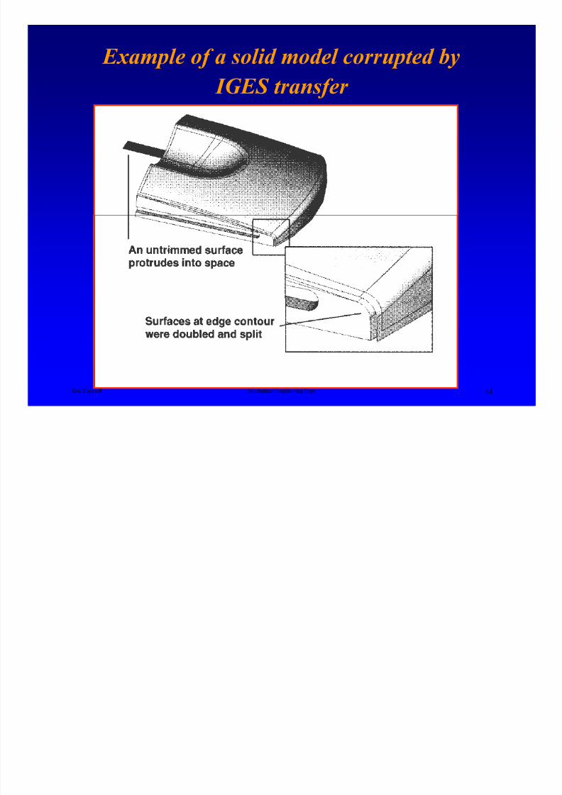
Example of a solid model corrupted by
8/4/2019 Plate Anlaysis
http://slidepdf.com/reader/full/plate-anlaysis 64/96
p f p y
IGES transfer
Ken Youssefi Mechanical Engineering Dept 64
FEA Pre-Processing
8/4/2019 Plate Anlaysis
http://slidepdf.com/reader/full/plate-anlaysis 65/96
g
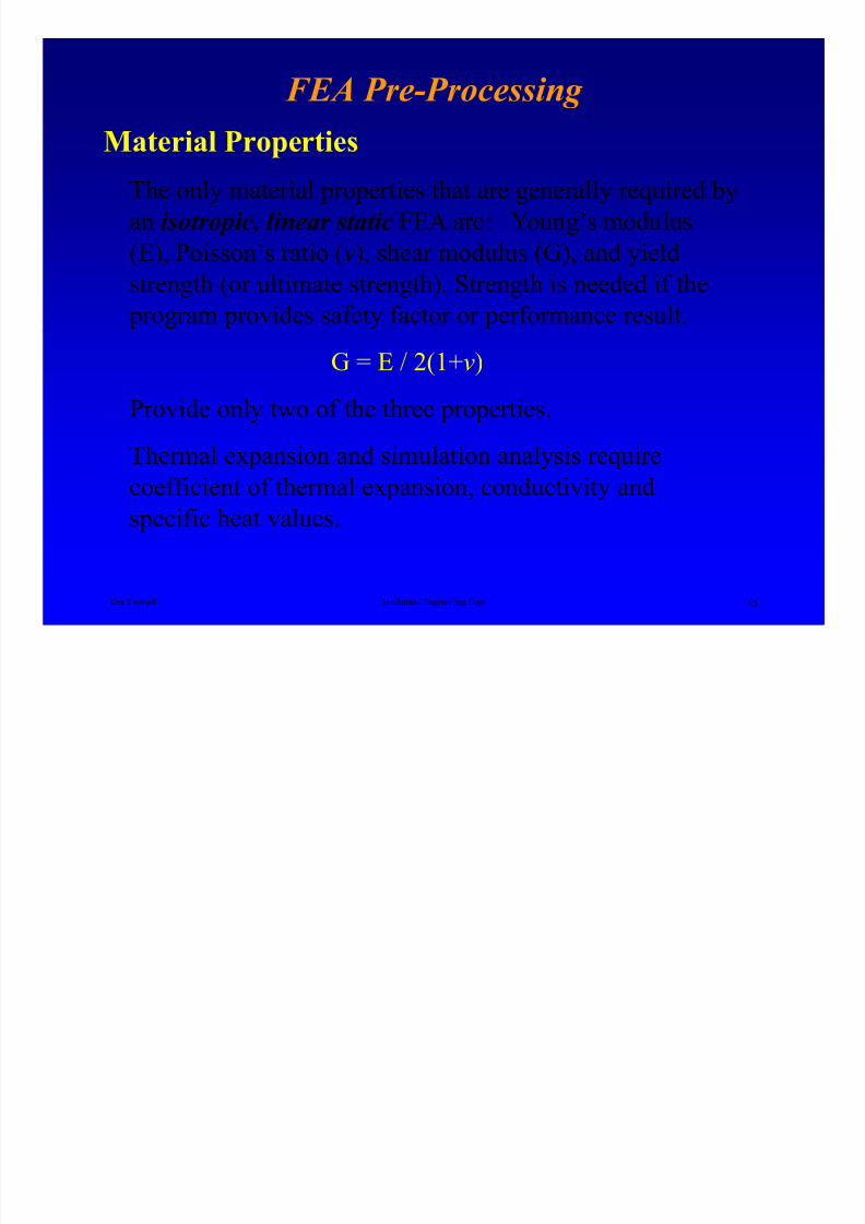
Material Properties
The only material properties that are generally required by
an isotropic, linear static FEA are: Young’s modulus
(E), Poisson’s ratio (v), shear modulus (G), and yieldstrength (or ultimate strength). Strength is needed if the
program provides safety factor or performance result.
Ken Youssefi Mechanical Engineering Dept 65
G = E / 2(1+v)
Provide only two of the three properties.
Thermal expansion and simulation analysis require
coefficient of thermal expansion, conductivity andspecific heat values.
FEA Pre-Processing
8/4/2019 Plate Anlaysis
http://slidepdf.com/reader/full/plate-anlaysis 66/96
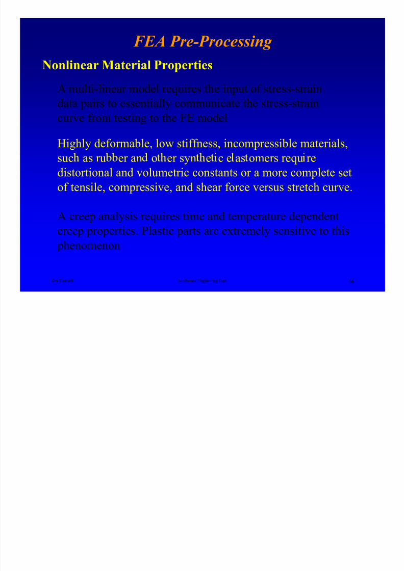
Nonlinear Material Properties
A multi-linear model requires the input of stress-strain
data pairs to essentially communicate the stress-strain
curve from testing to the FE model
Highly deformable, low stiffness, incompressible materials,
Ken Youssefi Mechanical Engineering Dept 66
suc as ru er an o er syn e c e as omers requ re
distortional and volumetric constants or a more complete setof tensile, compressive, and shear force versus stretch curve.
A creep analysis requires time and temperature dependent
creep properties. Plastic parts are extremely sensitive to this
phenomenon
FEA Pre-Processing

8/4/2019 Plate Anlaysis
http://slidepdf.com/reader/full/plate-anlaysis 67/96
• Their properties hold constant throughout the assigned entity.
• Average values are used (variation could be up to 15%).
CommentsIf you are selecting the property set from the code’s library,
be aware of the assumptions made with this selection.
Ken Youssefi Mechanical Engineering Dept 67
• Localized changes due to heat or other processing effects are
not accounted for.
• Any impurities present in the parent material are neglected.
If possible, obtain material property values specific to the
application under analysis.
FEA Pre-Processing

8/4/2019 Plate Anlaysis
http://slidepdf.com/reader/full/plate-anlaysis 68/96
Boundary Conditions (Loads and Constraints)
In FEA, the name of the game is “boundary condition”,
that is calculating the load and figuring out constraints
that each component experiences in its working
environment.
Ken Youssefi Mechanical Engineering Dept 68
“garbage in, garbage out”
The results of FEA should include a complete
discussion of the boundary conditions.
Boundary Conditions

8/4/2019 Plate Anlaysis
http://slidepdf.com/reader/full/plate-anlaysis 69/96
Loads
Loads are used to represent inputs to the system.
They can be in the forms of forces, moments (torque),
pressures, temperature, or accelerations.
Constraints
Ken Youssefi Mechanical Engineering Dept 69
Constraints are used as reactions to the appliedloads. Constraints can resist translational or
rotational deformation induced by applied loads.
Boundary Conditions
8/4/2019 Plate Anlaysis
http://slidepdf.com/reader/full/plate-anlaysis 70/96
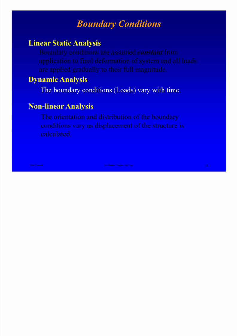
Linear Static Analysis
Boundary conditions are assumed constant from
application to final deformation of system and all loads
are applied gradually to their full magnitude.Dynamic Analysis
Ken Youssefi Mechanical Engineering Dept 70
.
Non-linear Analysis
The orientation and distribution of the boundary
conditions vary as displacement of the structure is
calculated.
Boundary Conditions

8/4/2019 Plate Anlaysis
http://slidepdf.com/reader/full/plate-anlaysis 71/96
Degrees of Freedom
Spatial DOFs refer to the three translational and three rotational
modes of displacement that are possible for any part in 3D
space. A constraint scheme must remove all six DOFs for theanalysis to run.
Ken Youssefi Mechanical Engineering Dept 71
or react to a load. The boundary condition cannot load or constrain a DOF that is not supported by the element to which it
is applied.
Boundary Conditions
8/4/2019 Plate Anlaysis
http://slidepdf.com/reader/full/plate-anlaysis 72/96
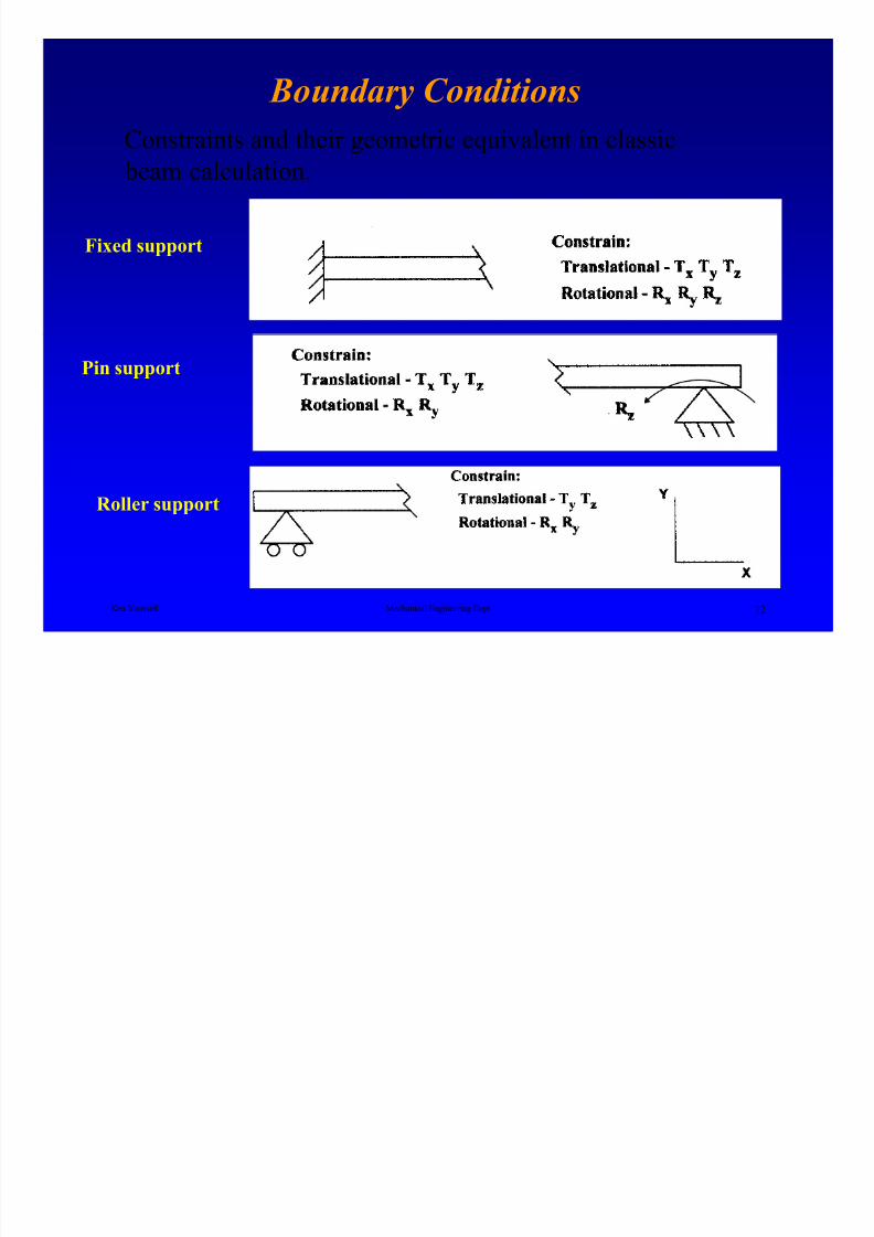
Constraints and their geometric equivalent in classic beam calculation.
Fixed support
Ken Youssefi Mechanical Engineering Dept 72
Roller support
Pin support
Boundary Conditions

8/4/2019 Plate Anlaysis
http://slidepdf.com/reader/full/plate-anlaysis 73/96
A solid face should always have at least three points in
contact with the rest of the structure. A solid element
should never be constrained by less than three points and
only translational DOFs must be fixed.
Accurac
Ken Youssefi Mechanical Engineering Dept 73
The choice of boundary conditions has a direct impact
on the overall accuracy of the model.
Over-constrained model – an overly stiff model due
to poorly applied constraints.
Boundary Conditions -Example

8/4/2019 Plate Anlaysis
http://slidepdf.com/reader/full/plate-anlaysis 74/96
Excessive ConstraintsModel of the chair seat with patches representing the tops of
the legs.
Ken Youssefi Mechanical Engineering Dept 74
Patch 3
Patch 1
Patch 2
Patch 4
Boundary Conditions -Example
It may appear to be acceptable to constrain each circular patch

8/4/2019 Plate Anlaysis
http://slidepdf.com/reader/full/plate-anlaysis 75/96
It may appear to be acceptable to constrain each circular patch
in vertical translation while leaving the rotational DOFs
unconstraint. This causes the seat to behave as if the leg-to-
seat interfaces were completely fixed.
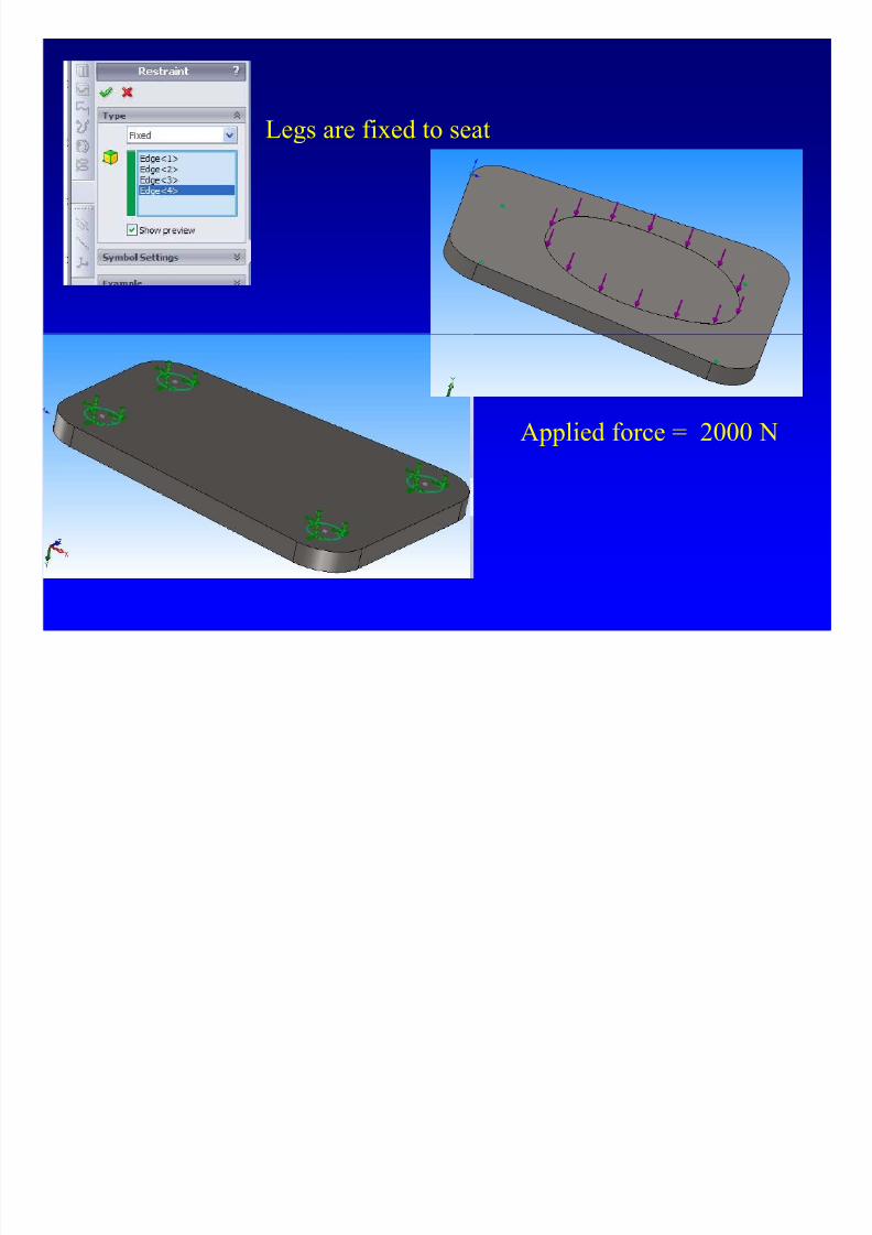
A more realistic constraint scheme would be to pin the
center point of each circular patch (translational), allowing
the patch to rotate. Each point should be fixed vertically,
Ken Youssefi Mechanical Engineering Dept 75
Patch 3
Patch 1
Patch 2
Patch 4
that in-plane spatial rotation and rigid body translation isremoved without causing excessive constraints.
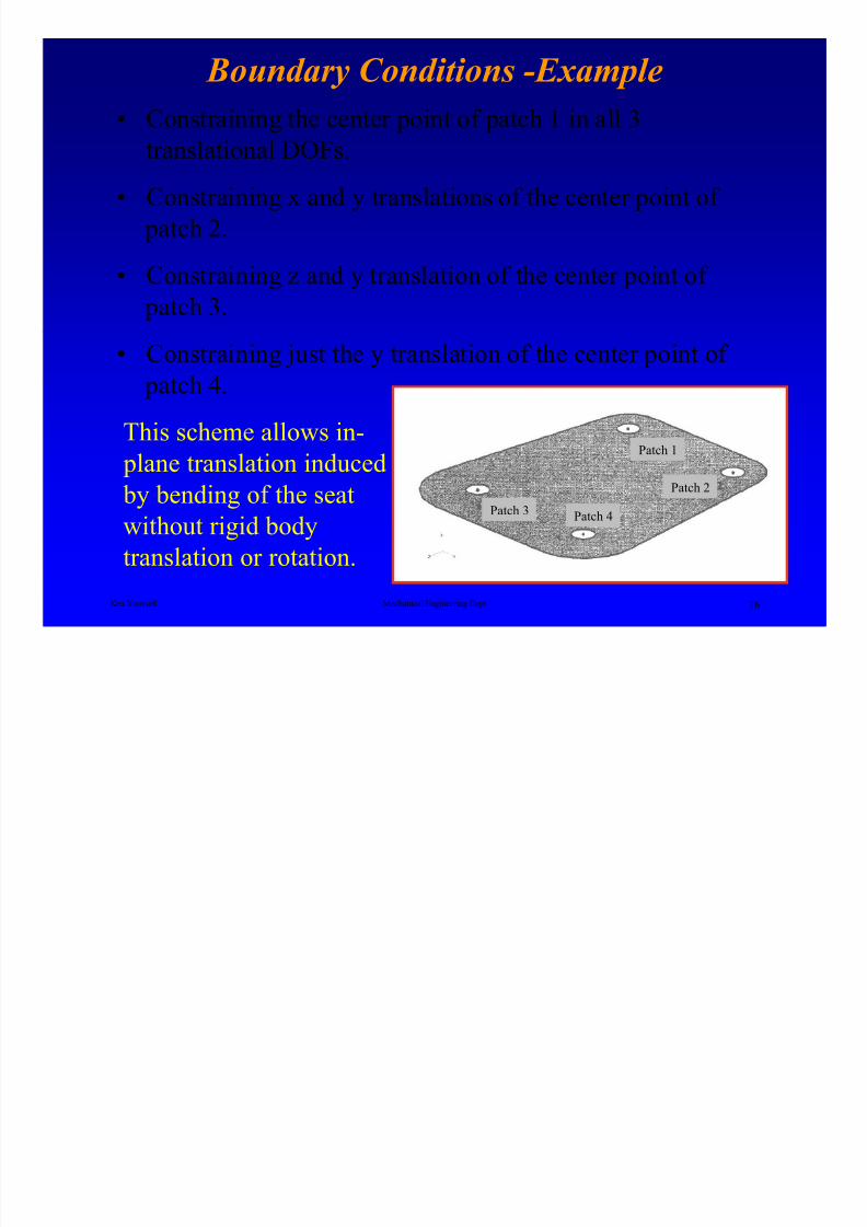
Boundary Conditions -Example
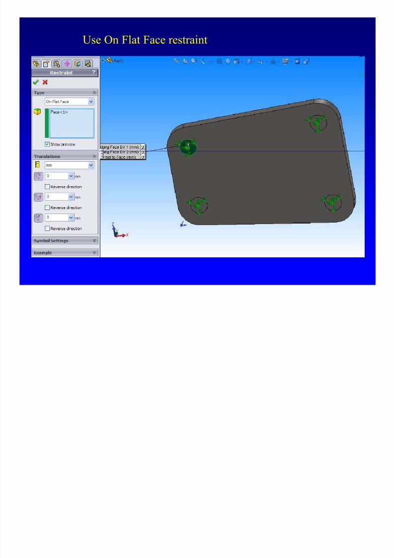
• Constraining the center point of patch 1 in all 3
8/4/2019 Plate Anlaysis
http://slidepdf.com/reader/full/plate-anlaysis 76/96
Constraining the center point of patch 1 in all 3
translational DOFs.
• Constraining x and y translations of the center point of
patch 2.
• Constraining z and y translation of the center point of
patch 3.
Ken Youssefi Mechanical Engineering Dept 76
• Constraining just the y translation of the center point of
patch 4.
This scheme allows in-
plane translation induced
by bending of the seatwithout rigid body
translation or rotation.
Patch 3
Patch 1
Patch 2
Patch 4
8/4/2019 Plate Anlaysis
http://slidepdf.com/reader/full/plate-anlaysis 77/96
Legs are fixed to seat
Applied force = 2000 N
Use On Flat Face restraint
8/4/2019 Plate Anlaysis
http://slidepdf.com/reader/full/plate-anlaysis 78/96
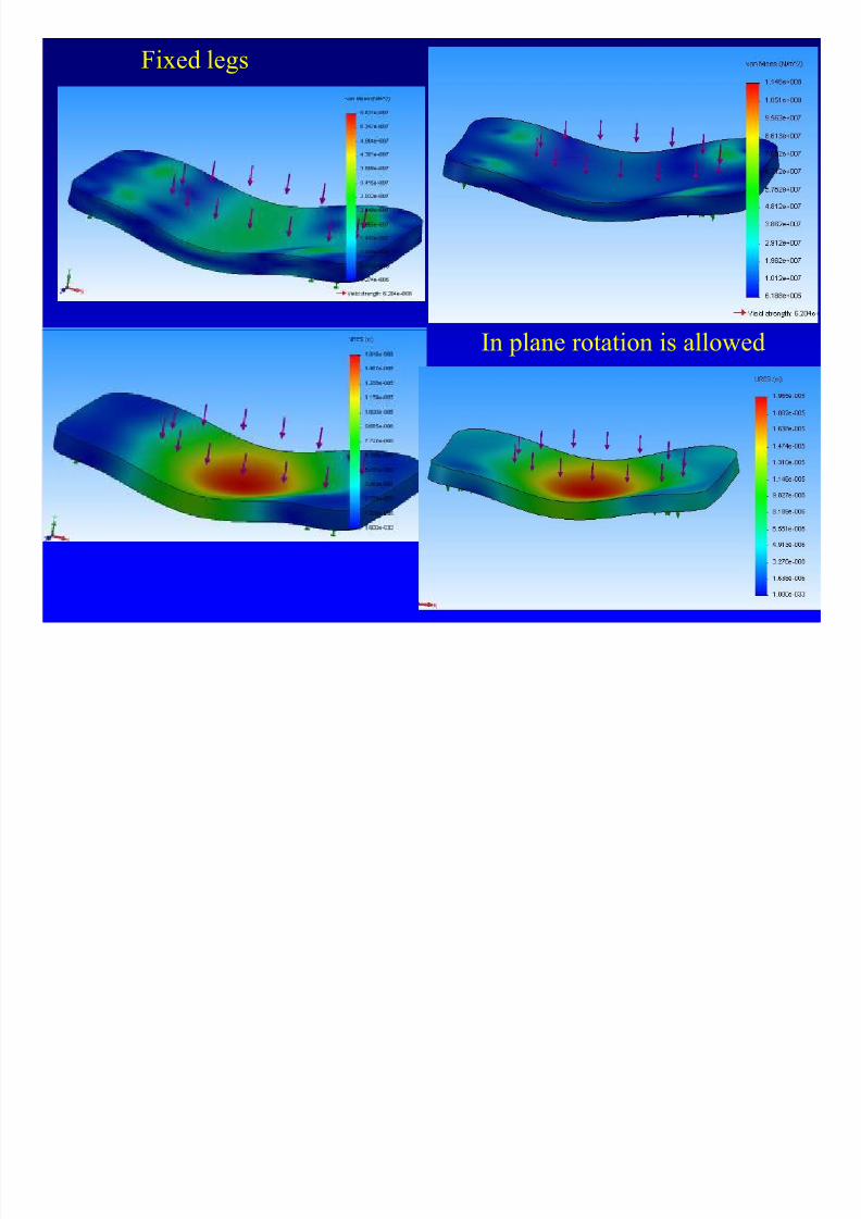
Fixed legs
8/4/2019 Plate Anlaysis
http://slidepdf.com/reader/full/plate-anlaysis 79/96
In plane rotation is allowed
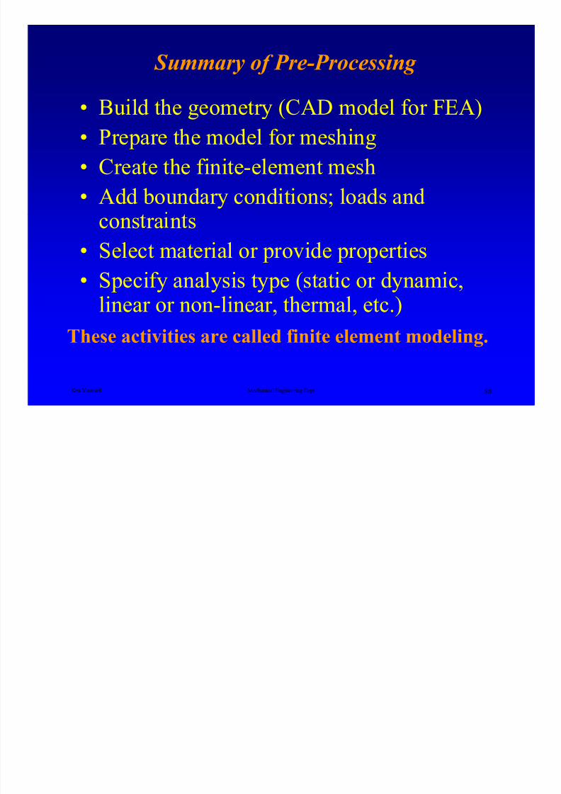
Summary of Pre-Processing
8/4/2019 Plate Anlaysis
http://slidepdf.com/reader/full/plate-anlaysis 80/96
• Build the geometry (CAD model for FEA)
• Prepare the model for meshing
• Create the finite-element mesh• Add boundary conditions; loads and
Ken Youssefi Mechanical Engineering Dept 80
cons ra n s
• Select material or provide properties
• Specify analysis type (static or dynamic,linear or non-linear, thermal, etc.)
These activities are called finite element modeling.
Solving the Model - Solver

8/4/2019 Plate Anlaysis
http://slidepdf.com/reader/full/plate-anlaysis 81/96
Once the mesh is complete, and the properties and
boundary conditions have been applied, it is time to solve
the model. In most cases, this will be the point where you
can take a deep breath, push a button and relax while thecomputer does the work for a change.
Ken Youssefi Mechanical Engineering Dept 81
In most cases submitting a run with multiple load cases will
be faster than running sequential, complete solutions for
each load case.
Final Model Check
Unexpectedly high or low displacements (by order of magnitude)
Post-Processing, Displacement Magnitude

8/4/2019 Plate Anlaysis
http://slidepdf.com/reader/full/plate-anlaysis 82/96
p y g p ( y g )
could be caused by an improper definition of load and/or elemental
properties.
Ken Youssefi Mechanical Engineering Dept 82
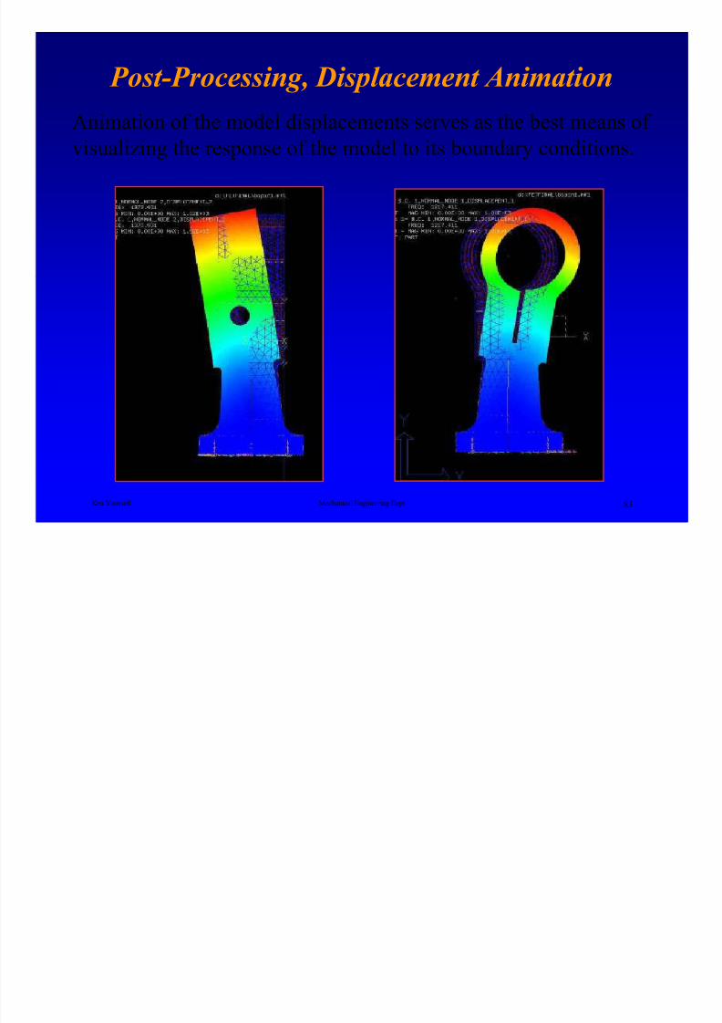
Post-Processing, Displacement Animation
8/4/2019 Plate Anlaysis
http://slidepdf.com/reader/full/plate-anlaysis 83/96
Animation of the model displacements serves as the best means of visualizing the response of the model to its boundary conditions.
Ken Youssefi Mechanical Engineering Dept 83
Post-Processing, FEA of a connecting rod

8/4/2019 Plate Anlaysis
http://slidepdf.com/reader/full/plate-anlaysis 84/96
Ken Youssefi Mechanical Engineering Dept84
Post-Processing, Stress Results

8/4/2019 Plate Anlaysis
http://slidepdf.com/reader/full/plate-anlaysis 85/96
Second Mode (Twisting)
The magnitude of the stresses should not be entirely unexpected.
Ken Youssefi Mechanical Engineering Dept85
First Mode (Bending)
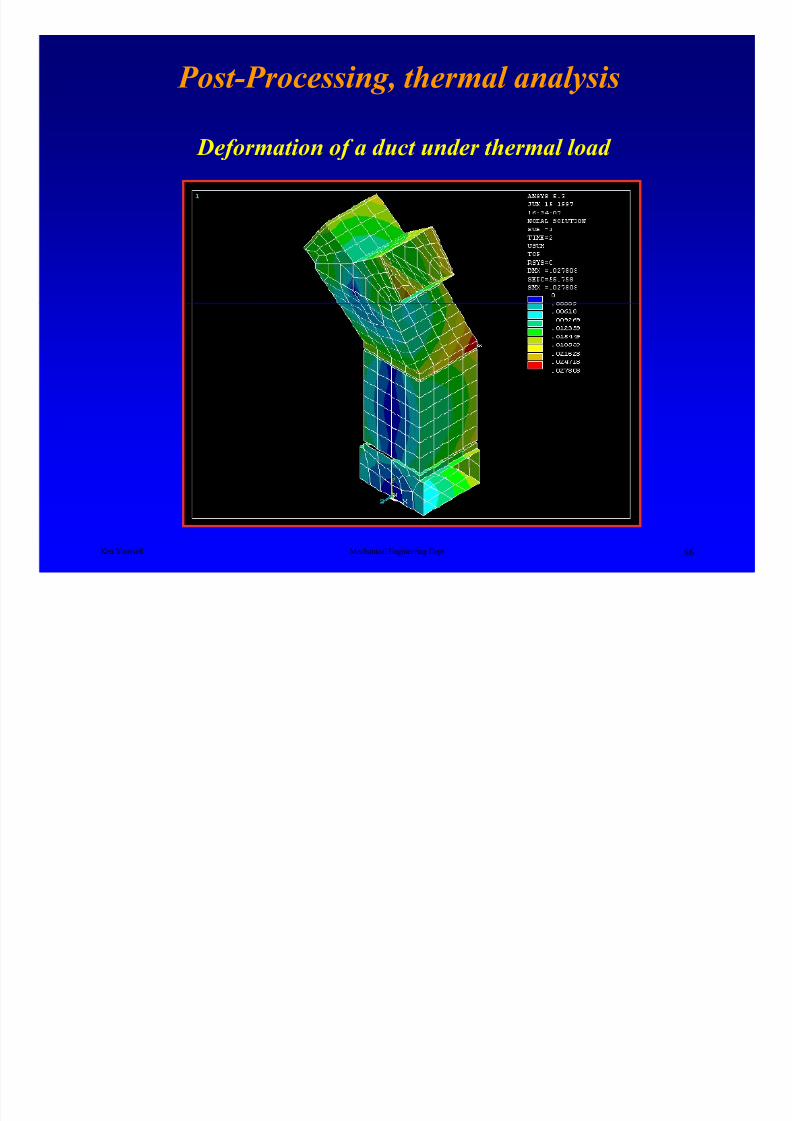
Post-Processing, thermal analysis
8/4/2019 Plate Anlaysis
http://slidepdf.com/reader/full/plate-anlaysis 86/96
Deformation of a duct under thermal load
Ken Youssefi Mechanical Engineering Dept
86
Deploy Mechanism – Assembly Analysis

8/4/2019 Plate Anlaysis
http://slidepdf.com/reader/full/plate-anlaysis 87/96
Displacement
Stress
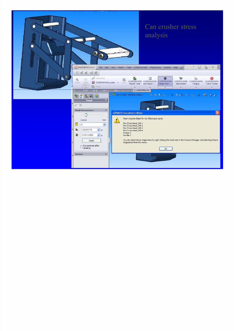
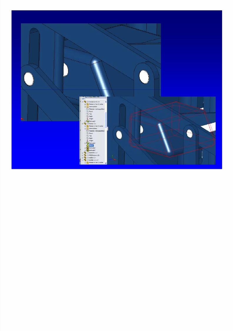
Can crusher stress
l i
8/4/2019 Plate Anlaysis
http://slidepdf.com/reader/full/plate-anlaysis 88/96
analysis
8/4/2019 Plate Anlaysis
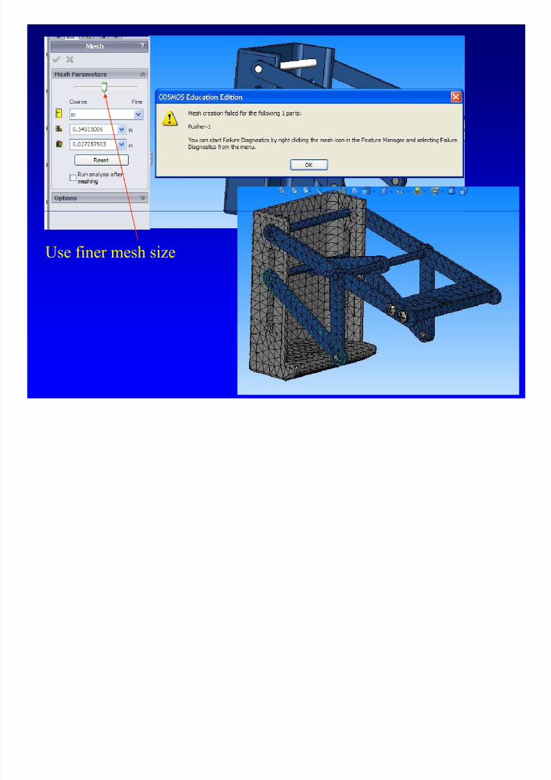
http://slidepdf.com/reader/full/plate-anlaysis 89/96
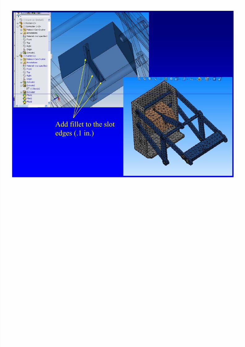
Use finer mesh size
Right click the
M h i d

8/4/2019 Plate Anlaysis
http://slidepdf.com/reader/full/plate-anlaysis 90/96
Mesh icon andchoose Failure
Diagnostics
8/4/2019 Plate Anlaysis
http://slidepdf.com/reader/full/plate-anlaysis 91/96

8/4/2019 Plate Anlaysis
http://slidepdf.com/reader/full/plate-anlaysis 92/96
8/4/2019 Plate Anlaysis
http://slidepdf.com/reader/full/plate-anlaysis 93/96
Add fillet to the slot
edges (.1 in.)
Max stress (von Mises) = 43.9 MPa
Sy = 96.5 MPa (Al 2014)
S f t f t
Apply 200 N
(45 lb)

8/4/2019 Plate Anlaysis
http://slidepdf.com/reader/full/plate-anlaysis 94/96
n = 96.5/43.9 = 2.2 > 2.0
Max deflection 1.13 mm < 2 mm
Safety factor
Design requirements
Safety factor between2.0-2.5 and deflection
less than 2 mm
Set gap as 5 in.
Fix the back plate
Post-Processing View (animated)
Displacements

8/4/2019 Plate Anlaysis
http://slidepdf.com/reader/full/plate-anlaysis 95/96
Does the shape of deformations make sense?
View Displacement
Fringe Plot
Yes
Review Boundary
Conditions
No
Are ma nitudes in line with our ex ectations?Review Load Magnitudes
No
Ken Youssefi Mechanical Engineering Dept 95
View Stress
Fringe Plot
Yes
Is the quality and mag. of stresses acceptable?
and Units
Review Mesh Density
and Quality of Elements No
View Results Specific
To the Analysis
Yes
FEA - Flow Chart
8/4/2019 Plate Anlaysis
http://slidepdf.com/reader/full/plate-anlaysis 96/96
Ken Youssefi Mechanical Engineering Dept 96