precision time protocol grandmaster clock
TRANSCRIPT
PRECISION TIME PROTOCOL GRANDMASTER CLOCK
SYSTEMIZATION AND DEVELOPMENT OF THE PROTOCOL HANDLER AND FUNCTIONAL BLOCKS ON FPGA
Sadiq Hemani
1
Examensarbete IL222X
Precision Time Protocol Grandmaster Clock
Sadiq Hemani
Godkänt
Examinator
Zhonghai Lu
Handledare
Per Liederg
Uppdragsgivare
Ericsson AB
2
Sammanfattning Med tanke på den ökade efterfrågan på exempelvis realtidsvideotjänster, är det uppenbart att högre krav ställs på timing och synkronisering och är därför kritiska för de infrastrukturer i nästa generationens nätverk. En av metoderna som telekomföretag har att hanterat detta är genom att använda en paketbaserat tidsfördelning som IEEE 1588 Precision Time Protocol (PTP). Med den andra versionen av protokollet även använts i Large Hadron Collider (LHR) vid CERN, bland flera andra tillämpningsområden (t.ex. telekombranschen), är det ett bevis på att PTP är en framtidssäker tid och frekvenssynkronisering lösning med tillräckligt intresse från en många olika intressegrupper. Synkroniseringsprotokoll kräver en mycket noggrann och stabil tidskälla, som fungerar som synkroniserings topologins främsta referens (som kallas för Grandmaster Klocka inom PTP). Förutom att fungera som en navigeringshjälp, ger GPS också en sådan exakt tidsreferens spridning med bekostnaden av en GPS-mottagare. Således är GPS ett populärt val för en tidsreferenskälla i synkroniseringsprotokoll som PTP.
Som huvudresultatet i denna avhandling, har en PTP Grandmaster Klocka utvecklats och funktionellt verifierats på en FPGA. Grandmaster Klockan är PTP-topologins huvudreferenskälla som distribuerar synkronisering till PTP Slave Klockor. En GPS-mottagare fungerar som Grandmasterns tidsreferenskälla i systemet där periodiska tid och datum uppdateras och sedan in i PTP-meddelanden, som i sin tur är fördelade över Ethernet till en eller fler PTP Slave Klockor. I avsaknad av en PTP Slave klocka, emuleras dess beteende med hjälp utav en laptop för att funktionellt verifiera designen av Grandmaster Klockan.
Trots att det var utanför omfattningen av avhandlingen, har en karakterisering med hjälp av ett verktyg lämpat för synkroniseringsprotokolls evaluering gjorts för att utvärdera de tidiga resultaten av denna design. Trots att resultaten inte uppnår samma nivå som liknande slutgiltiga implementationer av PTP Grandmaster Klockor, har vissa nyckelområden identifierats som en följd. De områden som bör förändras är i en viss mån en omdesign men går huvudsakligen ut på att ersätta funktionella block i systemets infrastruktur som har mer deterministiska och IEEE 1588 IP-kompatibla IP, t.ex. Ethernet MAC IP-blocket.
Om de rekommenderade förändringarna följts, bör designen implemterad i denna avhandling uppnå den potentiella synkroniseringsnoggrannhet som krävs för dagens applikationsbehov.
3
Master of Science Thesis IL222X
Precision Time Protocol Grandmaster Clock
Sadiq Hemani
Approved
Examiner
Zhonghai Lu
Supervisor
Per Liederg
Commissioner
Ericsson AB
4
Abstract Considering the growth in demand of for instance real-time video services, it is apparent that higher constraints are placed upon timing and synchronization and is hence mission critical for the next generation network infrastructures. One major way in which carriers have been coping with this, is by employing a packet-based timing distribution such as IEEE 1588 Precision Time Protocol (PTP). With the second version of the Protocol even used in the Large Hadron Collider at CERN, amongst various other application areas (such as the telecom industry), it is a testament to that PTP is a viable time and frequency synchronization solution with enough interest from a wide range of application groups. Synchronization protocols require a highly accurate and stable timing source, which serves as the synchronization topology’s primary reference (known as the Grandmaster Clock within PTP). Besides providing navigation assistance, GPS also provides such accurate time reference dissemination at the cost of a GPS-receiver. Thus GPS is a popular choice for a time reference source in synchronization protocols such as PTP.
The main result of this thesis, a PTP Grandmaster Clock, has been developed and functionally verified on an FPGA. A GPS-receiver serves as the time reference source in the system where periodic time and date information is updated and then inserted into PTP messages, which in turn are distributed over Ethernet to PTP Slave Clocks. In the absence of a PTP Slave clock, a laptop emulated the behavior of a PTP Slave Clock in order functionally verify the Grandmaster Clock implementation. This was done using Wireshark and Ostinato that together serve as a network packet analyzer to verify the packets transmitted from the Grandmaster and a packet-generation software to mimic a PTP Slave Clock respectively.
Although outside the scope of the thesis, a simpler characterization using a synchronization protocol evaluation tool (the IXIA Anue 3500) has been performed in order to evaluate the initial performance of this implementation.
Despite the performance not being on par with similar final implementations of PTP Grandmaster Clock, some key areas that require further effort have been identified. These areas include to some extent a redesign but mostly on replacing system infrastructure blocks with more deterministic and IEEE 1588-compliant IP blocks, i.e. the Ethernet MAC IP block.
It is believed that once these recommended changes are followed, the implementation would be capable of achieving the potential synchronization accuracy necessary for modern application needs.
5
FOREWORD
“It is said that engineers start out knowing nothing about everything, then learn more and more about less and less until knowing everything about nothing” – David L. Mills
I would like to acknowledge and express my deepest gratitude to the people who have inspired, supported and encouraged me in various ways while I was working on this thesis. Without you undertaking this task would not have been possible.
I would like to thank Per Liedberg at Ericsson, for his continuous support, encouragement and guidance as my supervisor throughout the course of the thesis.
Besides my supervisor, I would also like to thank Pierre Rohdin for selecting me to undertake this thesis and for his continuous support and checking into the office to make sure everything was going well.
I would also like to thank my Examiner Axel Jantsch for his invaluable feedback and constructive advice throughout the thesis.
Without the camaraderie of my fellow colleagues during the vital “fika” breaks, the darkest hours of the thesis would have engulfed and stifled my confidence and motivation. For those moments with you guys, I am forever grateful so thank you Emil, Ejaz, Jingying, Kenji, Victor and Yang.
With every step of the thesis, you were fervently struggling and rejoicing besides me on this journey. I would like to especially thank you for your love, encouragement and fighting spirit at every step on the way. Thank you my Tamago, without you, time would not advance and I would not be synchronized.
Last but not the least I would like to thank my parents for their unwavering and unconditional love, patience and support. Thank you for giving me strength I needed to complete not only this but challenges I have faced in life.
I almost forgot thank my brother. Thank you Aaloo for being an aaloo (the word in Hindi for potato).
Sadiq Hemani
Stockholm, July 2014
6
NOMENCLATURE
Abbreviations
BMCA Best Master Clock Algorithm
CDMA Code Division Multiple Access
FPGA Field Programmable Gate Array
GM Grandmaster Clock
GPS Global Positioning System
GSM Global System for Mobile Communications
IP Intellectual Property
ITU-T International Telecommunications Union Telecommunications (Standardization Sector)
LTE Long Term Evolution
NGN Next Generation Networks
NTP Network Time Protocol
PDV Packet Delay Variation
PTP Precision Time Protocol
PPS Pulse Per Second
PPS Parts Per Million
PPB Parts Per Billion
PSN Packet Switched Network
QOS Quality of Service
RTC Real Time Clock
RTL Register Transfer Level
RX Receive
TAI Temps Atomic International
TDM Time Division Multiplexing
TX Transmit
7
UTC Universal Time Coordinated
WCDMA Wideband Code Division Multiple Access
XDC Xilinx Design Constraints
8
TABLE OF CONTENTS
FOREWORD 5
1 INTRODUCTION 10
1.1 OVERVIEW 10 1.2 PURPOSE 10 1.3 DELIMITATIONS 11 1.4 METHODOLOGY 12 1.5 THESIS OUTLINE 13
2 BACKGROUND 15
2.1 SYNCHRONIZATION 15 2.1.1 CLOCK SYNCHRONIZATION 15 2.1.2 SYNCHRONIZATION TREND 17 2.1.3 CLOCK SYNCHRONIZATION QUALITY FACTORS 18 2.2 PRECISION TIME PROTOCOL 21 2.2.1 PROTOCOL MECHANISM 23 2.2.2 GRANDMASTER TIMESTAMPING 28 2.3 OTHER SYNCHRONIZATION PROTOCOLS 30 2.3.1 NETWORK TIME PROTOCOL 31 2.3.2 GPS CLOCK SYNCHRONIZATION 31 2.3.3 SYNC-E 32 2.3.4 COMPARISON WITH PTP 32 2.5 GPS AS A CLOCK REFERENCE SOURCE 34 2.5.1 GPS CLOCK 34 2.5.2 NMEA SENTENCES 35 2.6 RELATED WORK 36 2.6.1 HARDWARE REALIZATION OF IEEE 1588 SYNCHRONIZATION AND SYNTONIZATION FUNCTIONS [35] 36 2.6.2 FREQUENCY COMPENSATED HARDWARE IEEE-1588 IMPLEMENTATION [36] 37
3 IMPLEMENTATION 39
3.1 HARDWARE, DESIGN TOOLS AND ENVIRONMENT 39 3.1.1 FPGA DEVELOPMENT BOARD 39 3.1.2 GPS-RECEIVER 39 3.1.3 DESIGN AND VERIFICATION TOOLS 40 3.2 SYSTEM VIEW 41 3.3 DESIGN 42 3.3.1 PTP TIME CORRECTION 42 3.3.2 PTP PACKET GENERATOR 43 3.3.3 PTP GRANDMASTER IP 48 3.3.4 NMEA MESSAGE PARSING 49
9
3.3.5 ETHERNET MAC AND PHY 50 3.4 VERIFICATION 51 3.4.1 PACKET GENERATOR 51 3.4.2 GRANDMASTER IP 51 3.5 FPGA IP INTEGRATION 52 3.6 TEST ENVIRONMENT 54 3.6.1 FUNCTIONAL VERIFICATION 54
4 RESULTS 55
4.1 ACHIEVED GOALS 55 4.1.1 GRANDMASTER CLOCK 55 4.1.2 SYNTHESIS 57 4.1.3 CHARACTERIZATION 58
5 DISCUSSION AND FUTURE WORK 60
5.1 DISCUSSION 60 5.1.1 IMPLEMENTATION CHALLENGES 60 5.1.2 SOURCES OF ERROR 61 5.2 FUTURE WORK 62 5.3 CONCLUSION 63
6 REFERENCES 64
7 APPENDIX 68
A - IEEE 1588-2008 PTP MESSAGE HEADER 68 B – DEVELOPMENT WORK DISTRIBUTION 69
10
1 INTRODUCTION
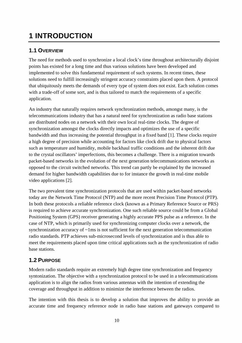
1.1 OVERVIEW The need for methods used to synchronize a local clock’s time throughout architecturally disjoint points has existed for a long time and thus various solutions have been developed and implemented to solve this fundamental requirement of such systems. In recent times, these solutions need to fulfill increasingly stringent accuracy constraints placed upon them. A protocol that ubiquitously meets the demands of every type of system does not exist. Each solution comes with a trade-off of some sort, and is thus tailored to match the requirements of a specific application.
An industry that naturally requires network synchronization methods, amongst many, is the telecommunications industry that has a natural need for synchronization as radio base stations are distributed nodes on a network with their own local real-time clocks. The degree of synchronization amongst the clocks directly impacts and optimizes the use of a specific bandwidth and thus increasing the potential throughput in a fixed band [1]. These clocks require a high degree of precision while accounting for factors like clock drift due to physical factors such as temperature and humidity, mobile backhaul traffic conditions and the inherent drift due to the crystal oscillators’ imperfections, this becomes a challenge. There is a migration towards packet-based networks in the evolution of the next generation telecommunications networks as opposed to the circuit switched networks. This trend can partly be explained by the increased demand for higher bandwidth capabilities due to for instance the growth in real-time mobile video applications [2].
The two prevalent time synchronization protocols that are used within packet-based networks today are the Network Time Protocol (NTP) and the more recent Precision Time Protocol (PTP). In both these protocols a reliable reference clock (known as a Primary Reference Source or PRS) is required to achieve accurate synchronization. One such reliable source could be from a Global Positioning System (GPS) receiver generating a highly accurate PPS pulse as a reference. In the case of NTP, which is primarily used for synchronizing computer clocks over a network, the synchronization accuracy of ~1ms is not sufficient for the next generation telecommunication radio standards. PTP achieves sub-microsecond levels of synchronization and is thus able to meet the requirements placed upon time critical applications such as the synchronization of radio base stations.
1.2 PURPOSE Modern radio standards require an extremely high degree time synchronization and frequency syntonization. The objective with a synchronization protocol to be used in a telecommunications application is to align the radios from various antennas with the intention of extending the coverage and throughput in addition to minimize the interference between the radios.
The intention with this thesis is to develop a solution that improves the ability to provide an accurate time and frequency reference node in radio base stations and gateways compared to
11
existing solutions. The aim is to with this solution is to improve the cost, ease of use, footprint, power, robustness and flexibility over existing solutions.
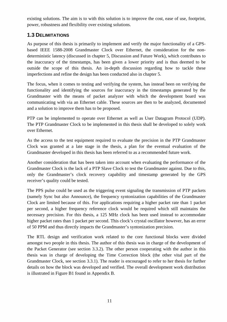
1.3 DELIMITATIONS As purpose of this thesis is primarily to implement and verify the major functionality of a GPS-based IEEE 1588-2008 Grandmaster Clock over Ethernet, the consideration for the non-deterministic latency (discussed in chapter 5, Discussion and Future Work), which contributes to the inaccuracy of the timestamps, has been given a lower priority and is thus deemed to be outside the scope of this thesis. An in-depth discussion regarding how to tackle these imperfections and refine the design has been conducted also in chapter 5.
The focus, when it comes to testing and verifying the system, has instead been on verifying the functionality and identifying the sources for inaccuracy in the timestamps generated by the Grandmaster with the means of packet analyzer with which the development board was communicating with via an Ethernet cable. These sources are then to be analyzed, documented and a solution to improve them has to be proposed.
PTP can be implemented to operate over Ethernet as well as User Datagram Protocol (UDP). The PTP Grandmaster Clock to be implemented in this thesis shall be developed to solely work over Ethernet.
As the access to the test equipment required to evaluate the precision in the PTP Grandmaster Clock was granted at a late stage in the thesis, a plan for the eventual evaluation of the Grandmaster developed in this thesis has been referred to as a recommended future work.
Another consideration that has been taken into account when evaluating the performance of the Grandmaster Clock is the lack of a PTP Slave Clock to test the Grandmaster against. Due to this, only the Grandmaster’s clock recovery capability and timestamp generated by the GPS receiver’s quality could be tested.
The PPS pulse could be used as the triggering event signaling the transmission of PTP packets (namely Sync but also Announce), the frequency syntonization capabilities of the Grandmaster Clock are limited because of this. For applications requiring a higher packet rate than 1 packet per second, a higher frequency reference clock would be required which still maintains the necessary precision. For this thesis, a 125 MHz clock has been used instead to accommodate higher packet rates than 1 packet per second. This clock’s crystal oscillator however, has an error of 50 PPM and thus directly impacts the Grandmaster’s syntonization precision.
The RTL design and verification work related to the core functional blocks were divided amongst two people in this thesis. The author of this thesis was in charge of the development of the Packet Generator (see section 3.3.2). The other person cooperating with the author in this thesis was in charge of developing the Time Correction block (the other vital part of the Grandmaster Clock, see section 3.3.1). The reader is encouraged to refer to her thesis for further details on how the block was developed and verified. The overall development work distribution is illustrated in Figure B1 found in Appendix B.
12
1.4 METHODOLOGY The goals of this thesis are briefly stated here to provide the reader with a general view of what each phase consists of and what the overall purpose with each milestone is. A more in-depth description of each phase can be found in chapter 4.2 (System Development Phases). A Work Breakdown Structure (WBS) can also be found in the Appendix, describing how each milestone is partitioned into smaller work phases.
Two people will carry out the development of the PTP Grandmaster, thus the emphasis of this thesis will be a subset of all the necessary functional modules. Both developers, however, have naturally carried out the integration phase together. The focus of this thesis is on the Protocol Handler and the necessary logic in the system to accommodate its functionality and implementing the IEEE 1588-2008 standard.
1. Study Phase: The IEEE 1588-2008 standard PTP over Ethernet is to be studied. The GPS receiver from Ublox that is to be used with the design outputs National Marine Electronics Association (NMEA) messages that provide time and date stamps periodically. This message format is to be studied and understood. A Xilinx Artix 7 FPGA will be used to map the hardware design. Xilinx Vivado Design Flow will be used for a Xilinx Intellectual Property (IP) centric design flow. Vivado will also be used for the back end portion of the design process. An initial familiarization with these tools is necessary in order to be able to incrementally add functional blocks and verify their functionality. Further, ARM’s AXI4-Lite memory-mapped bus will be used to configure and control an Ethernet MAC and PHY. An AXI4-Stream bus will serve as an interface to receive and transmit PTP packets over Ethernet. These standards need to be studied and understood. Before designing the PTP Grandmaster Clock, a brief investigation regarding the existing implementations with similar specifications and requirements will be conducted to facilitate the design choices in the development phase.
2. Development Phase: A SystemVerilog module for the IEEE 1588-2008 PTP protocol packet handling is to be designed. The protocol handler acts as the Grandmaster’s interface to the PTP clients connected over the network. The purpose of the protocol handler is to periodically send out and respond to PTP messages to and from clients over Ethernet. A testbench has to be developed to verify the protocol handler, initially to send and receive PTP messages in isolation. A GPS receiver sending messages in National Marine Electronics Association (NMEA) format along with an accurate reference 1 Pulse Per Second (PPS) will be connected to the PTP Grandmaster. The NMEA messages from the GPS-receiver are to be parsed to provide a timestamp and determine whether there is a fix on a GPS satellite. Using this, an on-board inaccurate clock source will be compensated for to create an accurate timestamp to be inserted into the PTP messages from the protocol handler. The logic development for the time compensation unit in the PTP Grandmaster is not the focus of this thesis and will thus only be discussed briefly. The reader is kindly referred to read the thesis “Time Compensation for GPS-based Precision Time Protocol Grandmaster Clock” for further details regarding how it was dimensioned, developed and tested.
13
3. Integration Phase: Connect, configure and verify the relevant functional blocks in Xilinx Vivado. The Ethernet MAC and PHY have to be configured to achieve an uplink with the laptop once connected with an Ethernet cable. The PPS pulse has to be brought in over the General Purpose Input Output (GPIO) from the GPS-receiver. The GPS-receiver’s NMEA stream has to be brought in via a serial stream using UART. An interrupt controller has to be connected to generate an interrupt whenever the UART’s FIFO fills up with data. A Xilinx MicroBlaze soft processor should then parse each character from the stream extracting the timestamp and GPS fix information.
4. Functional Test Phase: Connect the development board to a laptop with an Ethernet cable to test the Grandmaster’s PTP message transaction mechanism. The laptop shall passively emulate a PTP client sending and receiving PTP messages from the development board. The message format and along with an initial timestamp verification should be conducted to make sure the PTP protocol handler and time compensation blocks function as expected.
5. Performance Test Phase: Using a synchronization protocol validation device [] with options to simulate network load scenarios in typical mobile backhaul networks, test the accuracy of the timestamp generated by the Grandmaster and measure the wander and jitter of the on board clock. Document the performance of the developed PTP Grandmaster and diagnose where the lack in performance originate from. These will then be noted and compared to similar implementations and listed in the form of potential future improvements to the design.
6. Documentation Phase: Document and report in the form a Master thesis to serve as an
industrial documentation at Ericsson as well.
1.5 THESIS OUTLINE In the first chapter of this report a case is made for the thesis where a problem statement is formulated, limitations are identified and the general methodology employed in this thesis are listed.
In the second chapter the reader is presented with the necessary background regarding the purpose of synchronization in general and in the telecom industry, with a focus on the PTP protocol in particular. A comparison between the PTP protocol and other prevalent network synchronization protocols is also presented here. A frame of reference is also provided to the reader by summarizing the existing work relevant to this thesis. A summary of the design constraints and considerations as well as the design and test methodology employed throughout this thesis is also discussed here.
In the third chapter of the report, the implementation of the Grandmaster clock is systematically described starting from a functional overview of the entire system describing each constituent functional block. A detailed overview of how the protocol handler was developed and tested is also discussed here. A description of the hardware as well the design and verification tools used is also mentioned.
14
In chapter four the results from the functional and performance verification phases in the thesis are presented.
Chapter five then discusses these results, identifies and reflects upon the reasons for the loss in performance and then compares it to some of the related implementations brought up in chapter three in the form of a conclusion. A future work section then concludes this thesis by listing some improvements in form of recommendations on more detailed solutions and/or future work. A reflection on the entire process, how the Grandmaster Clock was envisioned, studied, implemented and verified, is also conducted here.
15
2 BACKGROUND
2.1 SYNCHRONIZATION
2.1.1 CLOCK SYNCHRONIZATION
Synchronization is defined as “The process of coordinating the network events in unison by complying accurately and precisely to the reference” [3].
The need for synchronization arises when interlinked processes within a system are required to work in conjunction or sequentially in a timely manner as intended. This is achieved by having a universal view of either explicit time in the form of a clock or implicit time, where process events can be assigned a relative order based discrete system events. It is sufficient, in some cases; to have a clock-less implicit system time view, whereas in other cases a clock is necessary for an exact measurement of the actual time elapsed in between each event [4].
Clocks are used as common reference points for components in a system to have unified view of time, so that the processes that each component will trigger or be triggered by occur in either a concurrent or consecutive order depending on the desired functionality and performance. A common view of time within a system also facilitates accurate measurement of time intervals or to determine the age of certain data [5]. Depending on the system topology, it may have a global clock to which each process is timed against as a reference or several spatially distributed clocks, which then require to be synchronized to each other.
A clock can be modeled with various degrees of accuracy, depending on the level of abstraction that is required to display the desired qualities. While at times a perfectly regular period in between the clock pulses in the form of square waves is sufficient, hiding the impairments and physical reality in terms of actual voltage levels. At other times, the physical imperfections of a clock’s crystal oscillator require the clock to be modeled as a waveform (sine wave).
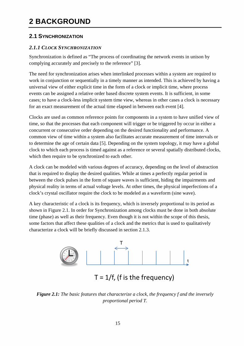
A key characteristic of a clock is its frequency, which is inversely proportional to its period as shown in Figure 2.1. In order for Synchronization among clocks must be done in both absolute time (phase) as well as their frequency. Even though it is not within the scope of this thesis, some factors that affect these qualities of a clock and the metrics that is used to qualitatively characterize a clock will be briefly discussed in section 2.1.3.
Figure 2.1: The basic features that characterize a clock, the frequency f and the inversely proportional period T.
16
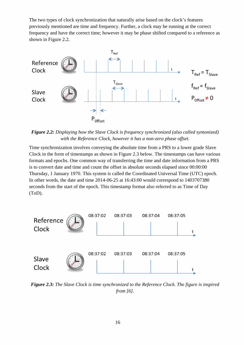
The two types of clock synchronization that naturally arise based on the clock’s features previously mentioned are time and frequency. Further, a clock may be running at the correct frequency and have the correct time; however it may be phase shifted compared to a reference as shown in Figure 2.2.
Figure 2.2: Displaying how the Slave Clock is frequency synchronized (also called syntonized) with the Reference Clock, however it has a non-zero phase offset.
Time synchronization involves conveying the absolute time from a PRS to a lower grade Slave Clock in the form of timestamps as shown in Figure 2.3 below. The timestamps can have various formats and epochs. One common way of transferring the time and date information from a PRS is to convert date and time and count the offset in absolute seconds elapsed since 00:00:00 Thursday, 1 January 1970. This system is called the Coordinated Universal Time (UTC) epoch. In other words, the date and time 2014-06-25 at 16:43:00 would correspond to 1403707380 seconds from the start of the epoch. This timestamp format also referred to as Time of Day (ToD).
Figure 2.3: The Slave Clock is time synchronized to the Reference Clock. The figure is inspired from [6].
17
2.1.2 SYNCHRONIZATION TREND
Control, automation and measurement systems are widely employed in areas such as robotics, power, aerospace and communications systems amongst others. Customarily, such systems have been realized using a centralized architecture where stringent timing requirements have been met by focusing on the programming and ensuring a deterministic communication latency. The system’s time is then dictated and maintained by one central server. However, a system could be comprised out of spatially distributed subsystems that still require a unified view of time, as they may be intended to work in conjunction. This gives rise to the concept of timing distribution over a network as a synchronization method.
As the paradigm has been shifting towards more distributed nodes over networks [7] the need for mechanisms that can cope with such system topologies are increasing. Another trend that shapes the emerging synchronization solutions is the increased degree of synchronization that is required in for instance the upcoming telecom standards. A clocks capability to maintain a precise time is highly susceptible physical factors such as clock quality, temperature (instantaneous and the rate of change), vibration, orientation, humidity, the crystal’s age and inherent degradation factor.
Cost is also driving factor behind the necessity to distribute timing information from higher quality oscillator to lower quality ones in distributed topologies. In a centralized system, having one highly accurate and stable clock is sufficient and the cost is thus justifiable. However, when a distributed architecture involves multiple clocks that need to maintain a high level of synchronization to each other, the option to use a high quality oscillator for each node of the network to allow for a long-term free-running accuracy and stability becomes too expensive. Thus having an accurate, stable and reliable clock serving as a reference (called the Primary Reference Source or PRS) to the rest of the lower grade clocks in a distributed system, is a way to maintain each clock’s integrity in terms of precision and simultaneously keeping the system’s cost at a reasonable level.
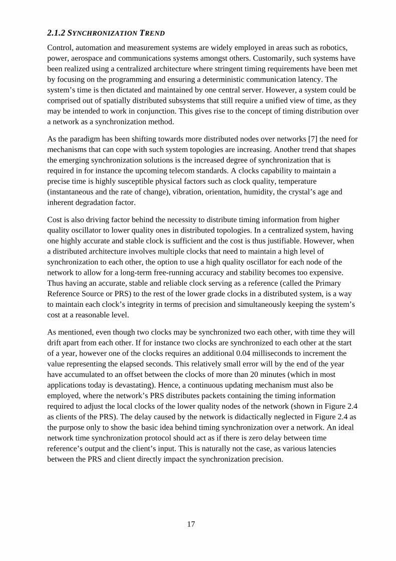
As mentioned, even though two clocks may be synchronized two each other, with time they will drift apart from each other. If for instance two clocks are synchronized to each other at the start of a year, however one of the clocks requires an additional 0.04 milliseconds to increment the value representing the elapsed seconds. This relatively small error will by the end of the year have accumulated to an offset between the clocks of more than 20 minutes (which in most applications today is devastating). Hence, a continuous updating mechanism must also be employed, where the network’s PRS distributes packets containing the timing information required to adjust the local clocks of the lower quality nodes of the network (shown in Figure 2.4 as clients of the PRS). The delay caused by the network is didactically neglected in Figure 2.4 as the purpose only to show the basic idea behind timing synchronization over a network. An ideal network time synchronization protocol should act as if there is zero delay between time reference’s output and the client’s input. This is naturally not the case, as various latencies between the PRS and client directly impact the synchronization precision.
18
Figure 2.4: A basic network time synchronization topology with a PRS distributing its local time to less accurate distributed clients’ clocks. In their turn, they adjust their local clocks based on
the difference between their own time and the reference’s.
2.1.3 CLOCK SYNCHRONIZATION QUALITY FACTORS
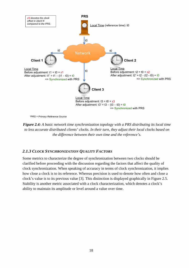
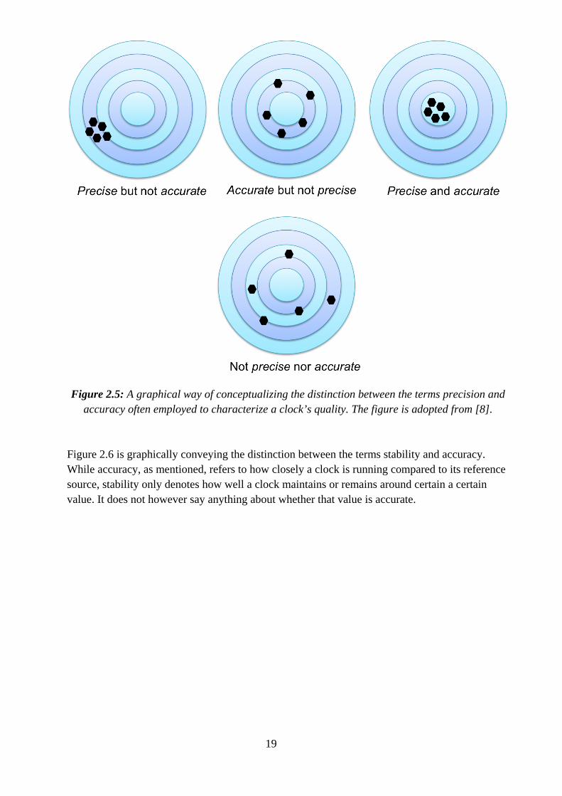
Some metrics to characterize the degree of synchronization between two clocks should be clarified before proceeding with the discussion regarding the factors that affect the quality of clock synchronization. When speaking of accuracy in terms of clock synchronization, it implies how close a clock is to its reference. Whereas precision is used to denote how often and close a clock’s value is to its previous value [3]. This distinction is displayed graphically in Figure 2.5. Stability is another metric associated with a clock characterization, which denotes a clock’s ability to maintain its amplitude or level around a value over time.
19
Figure 2.5: A graphical way of conceptualizing the distinction between the terms precision and accuracy often employed to characterize a clock’s quality. The figure is adopted from [8].
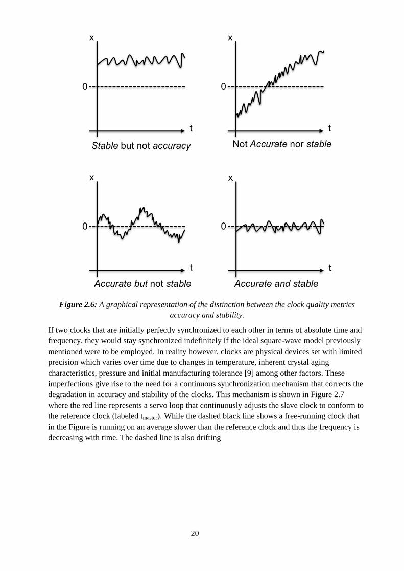
Figure 2.6 is graphically conveying the distinction between the terms stability and accuracy. While accuracy, as mentioned, refers to how closely a clock is running compared to its reference source, stability only denotes how well a clock maintains or remains around certain a certain value. It does not however say anything about whether that value is accurate.
20
Figure 2.6: A graphical representation of the distinction between the clock quality metrics accuracy and stability.
If two clocks that are initially perfectly synchronized to each other in terms of absolute time and frequency, they would stay synchronized indefinitely if the ideal square-wave model previously mentioned were to be employed. In reality however, clocks are physical devices set with limited precision which varies over time due to changes in temperature, inherent crystal aging characteristics, pressure and initial manufacturing tolerance [9] among other factors. These imperfections give rise to the need for a continuous synchronization mechanism that corrects the degradation in accuracy and stability of the clocks. This mechanism is shown in Figure 2.7 where the red line represents a servo loop that continuously adjusts the slave clock to conform to the reference clock (labeled tmaster). While the dashed black line shows a free-running clock that in the Figure is running on an average slower than the reference clock and thus the frequency is decreasing with time. The dashed line is also drifting

21
Figure 2.7: Displaying how a free-running slave clock’s oscillator is on an average running too slow versus a disciplined slave clock with continuous correction. Inspired from [10].
Although a clock reference might be of the highest quality in terms of accuracy, precision and stability, this has to be conveyed to the lower grade slave node clocks with an as high fidelity as possible by minimizing the degradation of the clock qualities throughout the path. A factor behind the degradation in the synchronization message from a reference clock is primarily the non-zero delay in transporting the message to the slave node over a network. As was shown in Figure 2.4, if no network delay impedes a synchronization message, the message that leaves a PRS is sufficient to accurately synchronize the slave node’s clock. This is rarely the case and thus mechanisms are required to compensate for these additional path delays by adding the time required for the transport to the synchronization message itself. This way the on-path delay is also accounted for in the synchronization message.
2.2 PRECISION TIME PROTOCOL The IEEE 1588 Precision Time Protocol (PTP) is a packet-based network synchronization protocol that organizes itself into clock domain(s) in which a highly accurate time reference source (known as the Primary Reference Source or PRS) is elected which then corrects the other less accurate clocks by periodically adjusting their local clocks’ offset via synchronization packets containing accurate timestamps in both second and nanosecond resolutions. The logical scope in which a sole Grandmaster is viewed as the PRS by the remaining Slave Clocks constitutes a PTP domain. This Master-Slave PTP topology is inherently independent of the underlying network it operates over. Thus it decouples system processes from propagation times of communication in order to achieve the necessary determinism in the real-time clocks at each network node. The PTP enables synchronous clocks running in decentralized topologies to coordinate their processes with each other chronologically by decoupling the completion of a process from the communication and processing of control commands [11].
The first version of the protocol was proposed in 8th November 2002 as IEEE 1588-2002 with a second version being standardized year 2008 called the IEEE 1588-2008. The first version was targeted to achieve sub-microsecond synchronization of real-time clocks in nodes of a distributed
22
control and measurement system over a network [12]. It was also intended to relatively small and localized systems that are commonly found in test and measurement environments as well as in industrial automation. It required minimum resources on the network it operated on and supported heterogeneous clock schemes with variable precision and stability. The second version of PTP improves in terms of accuracy, precision and robustness.
A network on which a PTP system is deployed can consist of a mix of PTP and non-PTP devices. The key PTP devices are:
Grandmaster Clock: The PRS within a PTP domain, which generally has a highly precise time source (typically a GPS reference with an Atomic Clock).
Ordinary Clock: A device with a single physical port functioning either as a slave or reference (Grandmaster) node in the PTP network provided it has access to a highly precise reference source. As the name suggests, the Ordinary Clocks is the most populous device in a PTP network and is usually attached to nodes that require synchronization [13].
Boundary Clock: Defined as a PTP clock with more than a one port. Its role is to provide an interface between separate PTP domains. Boundary clocks also have a local clock to compensate for the transit time of PTP messages when crossing between PTP domains.
Transparent Clock: Introduced in the second version of the standard (IEEE 1588-2008) as an improved alternative to the Boundary Clock. The Transparent Clock adds the residence time to the timestamps in PTP messages as they pass through. It achieves this by locally time stamping the ingress and egress time points.
The main functionality of Boundary Clocks and Transparent clocks is to compensate and alleviate Packet Delay Variations (PDV) in the PTP network. However, the Transparent Clock scales better in cascaded topologies [14].
Some of the key features of the IEEE 1588-2008 protocol include:
Sub-microsecond to nanosecond level of synchronization accuracy using hardware timestamping.
Clock domain support ideal for heterogeneous network architectures (nodes with diverse clock characteristics).
Self-assembling and self-administrating protocol with minimal maintenance. Built-in fault tolerance with passive Grandmasters on standby, in case the elected
Grandmaster’s clock quality is degraded. Timestamp propagation non-determinism (due to variations in network traffic from
switches and routers) is taken into account and compensated for in the protocol. Can be implemented on low-end and low-cost devices. A protocol that is inherently independent of the underlying network as only the final
slave node that needs it is synchronized [15]. Can be incorporated into existing network infrastructure, i.e. Ethernet LAN, thus the
required network and computing resources are kept to a minimum. The addition of the Transparent Clock, which allows for a higher degree of scalability
compared to IEEE 1588-2002’s Boundary Clock. Higher message rates, compared to the first version’s limit of 1 message per second.
23
1588-2008 also introduces a new concept of profiles as “The set of allowed Precision Time Protocol (PTP) features applicable to a device” [16]. Thereby, organizations are able to specify tailored selections of attributes and optional features that meet the requirements of their particular area of interest. One example of such a standardization organization is the International Telegraph Union Telecommunication Standardization Sector (ITU-T) that addresses telecom applications.
In PTP, the timestamps in the second resolution are in the International Atomic Time (TAI) epoch and can be converted to the Coordinated Universal Time (UTC) epoch. The UTC time standard is widely employed in international timekeeping and uses the International Standard (SI) definition of the second, which is based on atomic clocks. The TAI time standard is a high-precision time scale that is a weighted average of the time managed by over 200 atomic clocks (of which most are Cesium atomic clocks) in over 50 national laboratories all over the world.
The offset between the TAI and UTC time standards is in the form of, as of June 30 2012, 35 leap seconds. Leap seconds are adjustments of one second that is occasionally added to UTC time. The addition of leap seconds are decided and managed by the International Earth Rotation and Reference Systems Service (IERS).
The timestamps in the nanosecond resolution are usually generated locally using a disciplined local oscillator, which is used to increment nanoseconds at the arrival of clock flanks.
2.2.1 PROTOCOL MECHANISM PTP enables time synchronization and frequency syntonization propagation throughout a hierarchical master-slave topology, by periodically electing a reliable and accurate PRS within a clock domain. This reference clock, denoted the Grandmaster Clock, then serves as an accurate time reference with a higher quality clock than the rest of the clock domain nodes who then become the Grandmaster’s slaves. The Grandmaster’s time reference source could be a GPS receiver with a fix on one or more satellites directly or indirectly via a CDMA antenna [17].
The time synchronization mechanism is divided into two main phases: offset and path delay [18]. The offset is calculated by the Slave Clock comparing its local clock to the timestamp received from the Grandmaster in the form of a Sync Message. As shown in Figure 2.7, the time at which the Sync message leaves the interface of the Grandmaster is sent in the form of a timestamp (T1). The time at which the Sync message arrives at the slave is also locally time stamped (T2) and hence the absolute offset between the Slave Clock and Grandmaster Clock can be determined as shown in Equation 2.1.
The Sync message mechanism comes in two variants depending on whether the Grandmaster is configured as a One-Step or Two-Step Clock. The One-Step variant, as in the example shown in Figure 2.6, sends the timestamp with the Sync message on-the-fly. Whereas in the Two-Step Clock mode a Follow_Up type message is sent right after every Sync message containing the timestamp plus the dwell time of the Sync message instead. The choice of using one mode over the other is heavily dependent on the PTP Grandmaster topology and how and more importantly where the timestamp is inserted into the Sync messages. This will be discussed in the following section (2.2.2) and the ramifications of each choice will also be described.
24
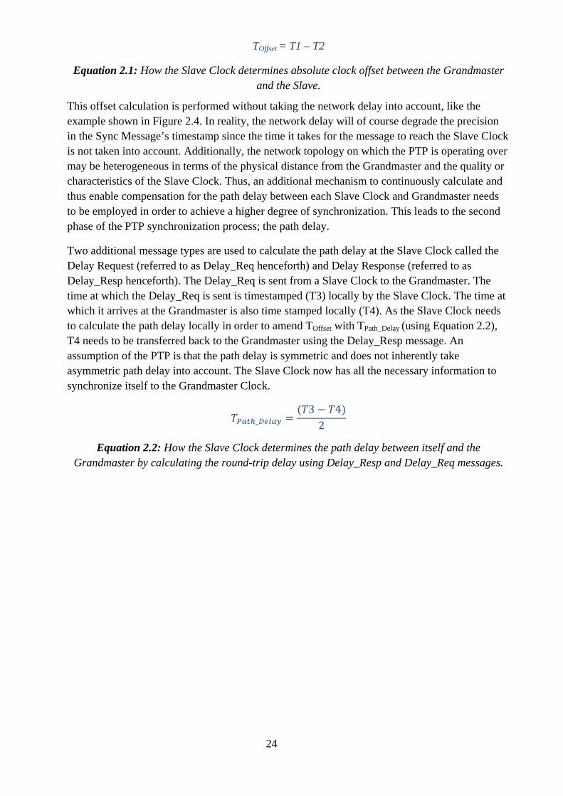
TOffset = T1 – T2
Equation 2.1: How the Slave Clock determines absolute clock offset between the Grandmaster and the Slave.
This offset calculation is performed without taking the network delay into account, like the example shown in Figure 2.4. In reality, the network delay will of course degrade the precision in the Sync Message’s timestamp since the time it takes for the message to reach the Slave Clock is not taken into account. Additionally, the network topology on which the PTP is operating over may be heterogeneous in terms of the physical distance from the Grandmaster and the quality or characteristics of the Slave Clock. Thus, an additional mechanism to continuously calculate and thus enable compensation for the path delay between each Slave Clock and Grandmaster needs to be employed in order to achieve a higher degree of synchronization. This leads to the second phase of the PTP synchronization process; the path delay.
Two additional message types are used to calculate the path delay at the Slave Clock called the Delay Request (referred to as Delay_Req henceforth) and Delay Response (referred to as Delay_Resp henceforth). The Delay_Req is sent from a Slave Clock to the Grandmaster. The time at which the Delay_Req is sent is timestamped (T3) locally by the Slave Clock. The time at which it arrives at the Grandmaster is also time stamped locally (T4). As the Slave Clock needs to calculate the path delay locally in order to amend TOffset with TPath_Delay (using Equation 2.2), T4 needs to be transferred back to the Grandmaster using the Delay_Resp message. An assumption of the PTP is that the path delay is symmetric and does not inherently take asymmetric path delay into account. The Slave Clock now has all the necessary information to synchronize itself to the Grandmaster Clock.
𝑇𝑃𝑎𝑡ℎ_𝐷𝑒𝑙𝑎𝑦 =(𝑇3 − 𝑇4)
2
Equation 2.2: How the Slave Clock determines the path delay between itself and the Grandmaster by calculating the round-trip delay using Delay_Resp and Delay_Req messages.
25
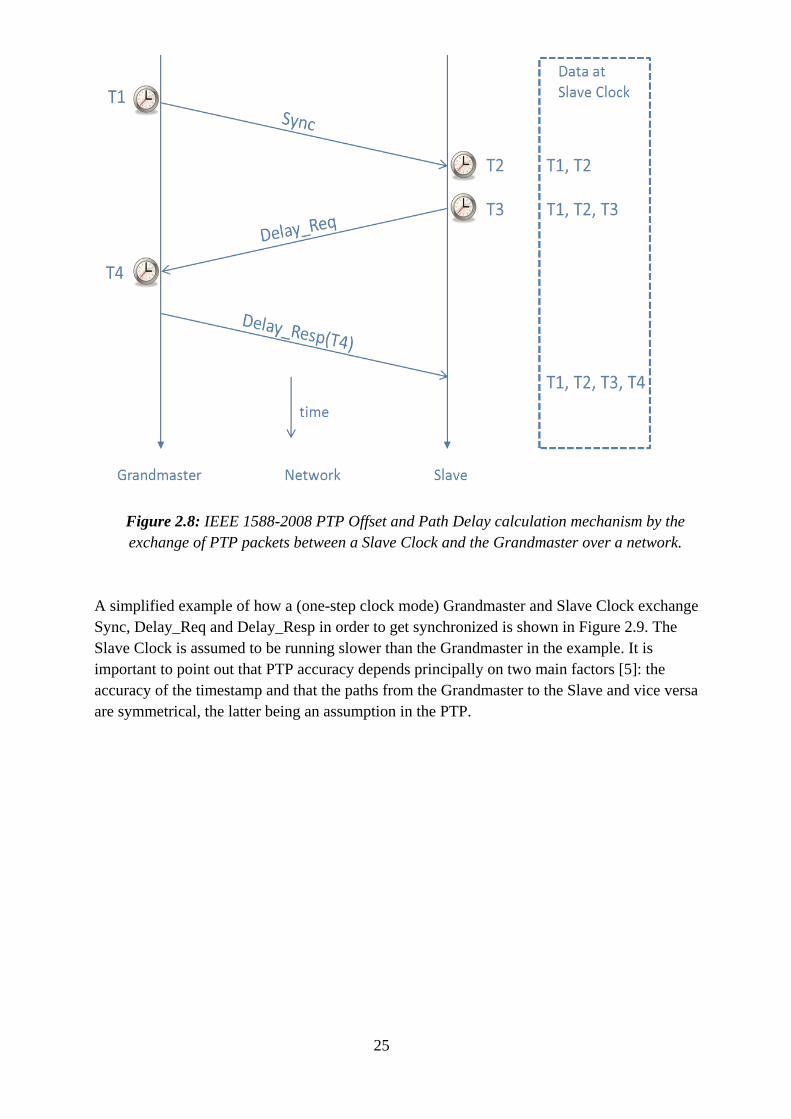
Figure 2.8: IEEE 1588-2008 PTP Offset and Path Delay calculation mechanism by the exchange of PTP packets between a Slave Clock and the Grandmaster over a network.
A simplified example of how a (one-step clock mode) Grandmaster and Slave Clock exchange Sync, Delay_Req and Delay_Resp in order to get synchronized is shown in Figure 2.9. The Slave Clock is assumed to be running slower than the Grandmaster in the example. It is important to point out that PTP accuracy depends principally on two main factors [5]: the accuracy of the timestamp and that the paths from the Grandmaster to the Slave and vice versa are symmetrical, the latter being an assumption in the PTP.
26
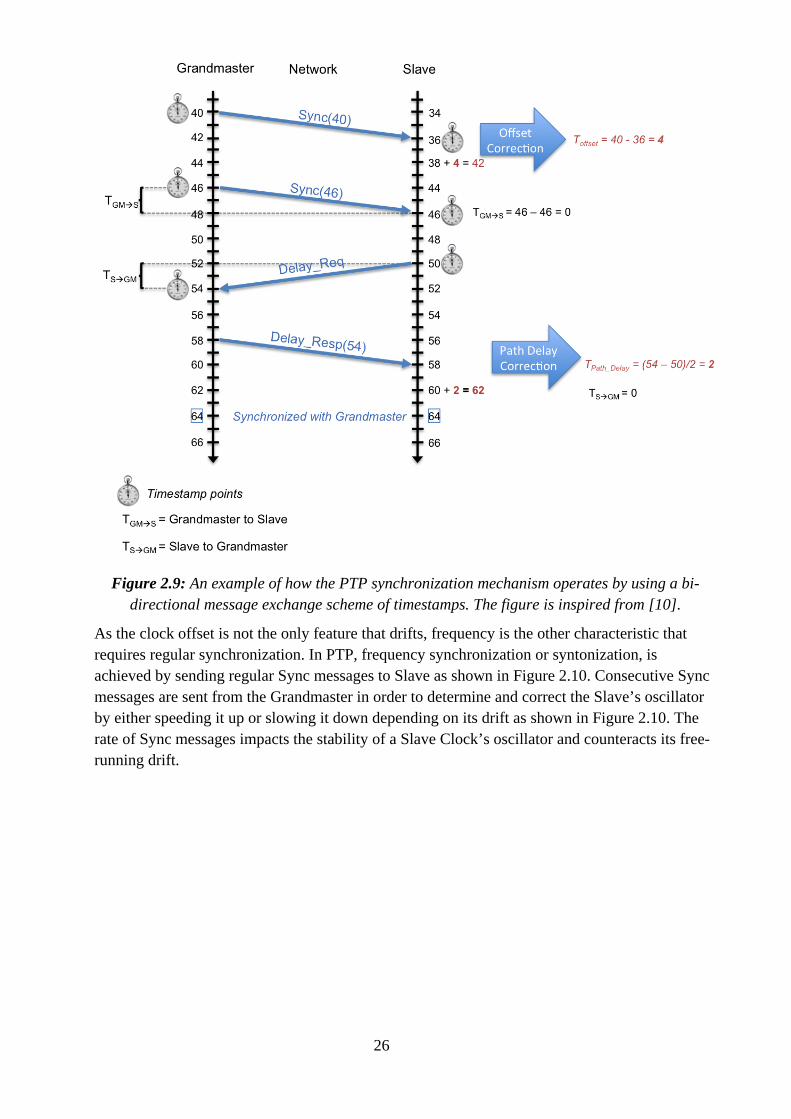
Figure 2.9: An example of how the PTP synchronization mechanism operates by using a bi-directional message exchange scheme of timestamps. The figure is inspired from [10].
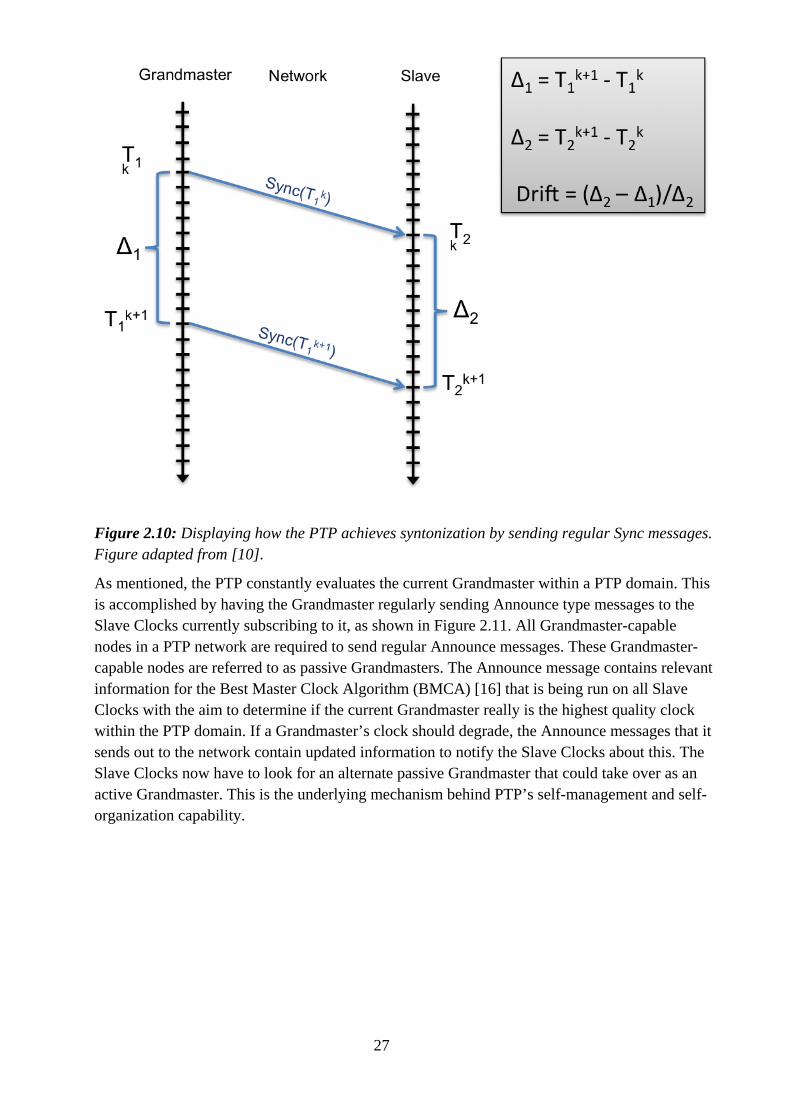
As the clock offset is not the only feature that drifts, frequency is the other characteristic that requires regular synchronization. In PTP, frequency synchronization or syntonization, is achieved by sending regular Sync messages to Slave as shown in Figure 2.10. Consecutive Sync messages are sent from the Grandmaster in order to determine and correct the Slave’s oscillator by either speeding it up or slowing it down depending on its drift as shown in Figure 2.10. The rate of Sync messages impacts the stability of a Slave Clock’s oscillator and counteracts its free-running drift.
27
Figure 2.10: Displaying how the PTP achieves syntonization by sending regular Sync messages. Figure adapted from [10].
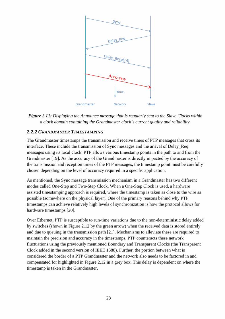
As mentioned, the PTP constantly evaluates the current Grandmaster within a PTP domain. This is accomplished by having the Grandmaster regularly sending Announce type messages to the Slave Clocks currently subscribing to it, as shown in Figure 2.11. All Grandmaster-capable nodes in a PTP network are required to send regular Announce messages. These Grandmaster-capable nodes are referred to as passive Grandmasters. The Announce message contains relevant information for the Best Master Clock Algorithm (BMCA) [16] that is being run on all Slave Clocks with the aim to determine if the current Grandmaster really is the highest quality clock within the PTP domain. If a Grandmaster’s clock should degrade, the Announce messages that it sends out to the network contain updated information to notify the Slave Clocks about this. The Slave Clocks now have to look for an alternate passive Grandmaster that could take over as an active Grandmaster. This is the underlying mechanism behind PTP’s self-management and self-organization capability.
28
Figure 2.11: Displaying the Announce message that is regularly sent to the Slave Clocks within a clock domain containing the Grandmaster clock’s current quality and reliability.
2.2.2 GRANDMASTER TIMESTAMPING
The Grandmaster timestamps the transmission and receive times of PTP messages that cross its interface. These include the transmission of Sync messages and the arrival of Delay_Req messages using its local clock. PTP allows various timestamp points in the path to and from the Grandmaster [19]. As the accuracy of the Grandmaster is directly impacted by the accuracy of the transmission and reception times of the PTP messages, the timestamp point must be carefully chosen depending on the level of accuracy required in a specific application.
As mentioned, the Sync message transmission mechanism in a Grandmaster has two different modes called One-Step and Two-Step Clock. When a One-Step Clock is used, a hardware assisted timestamping approach is required, where the timestamp is taken as close to the wire as possible (somewhere on the physical layer). One of the primary reasons behind why PTP timestamps can achieve relatively high levels of synchronization is how the protocol allows for hardware timestamps [20].
Over Ethernet, PTP is susceptible to run-time variations due to the non-deterministic delay added by switches (shown in Figure 2.12 by the green arrow) when the received data is stored entirely and due to queuing in the transmission path [21]. Mechanisms to alleviate these are required to maintain the precision and accuracy in the timestamps. PTP counteracts these network fluctuations using the previously mentioned Boundary and Transparent Clocks (the Transparent Clock added in the second version of IEEE 1588). Further, the portion between what is considered the border of a PTP Grandmaster and the network also needs to be factored in and compensated for highlighted in Figure 2.12 in a grey box. This delay is dependent on where the timestamp is taken in the Grandmaster.

29
Figure 2.12: PTP Grandmaster-Slave topology with the main on-path delays for a PTP message.
As shown in Figure 2.13, depending on the implementation of the Grandmaster, various options exist as potential timestamp points. Two-Step Clock mode does not require any special hardware to insert the timestamp in the PTP messages (depicted by the red “t1” in Figure 2.13) as the timestamp is taken in Network Interface Card (NIC) driver itself. The PTP software requires an interface to the timestamp hardware in order to access the timestamps transmitted and received. Additionally, the software needs information about the exchanged PTP messages to correlate the timestamps with the messages. The advantage of timestamping at the application layer (at t1 in Figure 2.13) is that the protocol is independent of the platform. The disadvantage however, is that the non-deterministic message transit delay through the protocol stack. This delay is caused by the operating system (also depending on the type of operating system), other application running, the system hardware and the interrupt mechanism [19].
Another option for a timestamping point is at the driver level (shown by blue “t1” in Figure 2.13). In order to timestamp at the driver level, a modification of the network driver is required. PTP messages are timestamped at the end of a send routine when transmitted as Ethernet frames. This could for instance be at the interface to the Media Access Controller (MAC) controller where the frame is passed to the hardware. In the receive direction, the frame is timestamped directly when an Interrupt Service Routine (ISR) has been called to service the network interface. This way, timestamping at the driver level is the optimal software implementation method [19].
When using a One-Step Clock, hardware assisted timestamp logic is required that inserts the timestamp on-the-fly. Shown in Figure 2.13 “t3”, the hardware timestamp is taken at the Media Independent Interface (MII) between the MAC and the Physical Layer (PHY). In order to achieve this, a local clock timestamps the messages before being sent or received over the
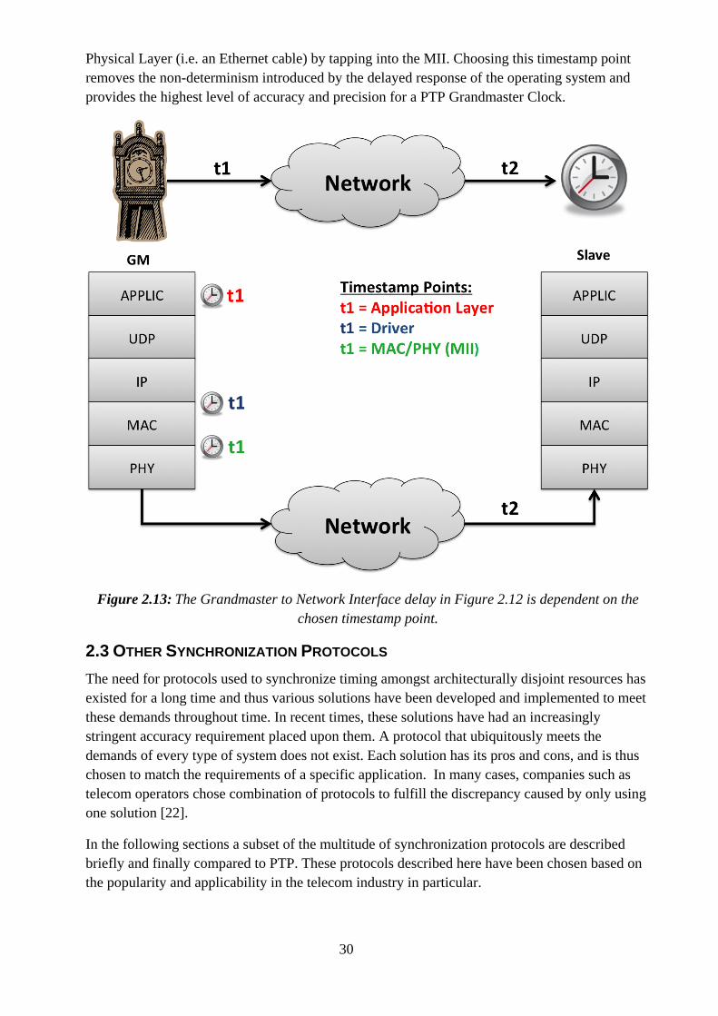
30
Physical Layer (i.e. an Ethernet cable) by tapping into the MII. Choosing this timestamp point removes the non-determinism introduced by the delayed response of the operating system and provides the highest level of accuracy and precision for a PTP Grandmaster Clock.
Figure 2.13: The Grandmaster to Network Interface delay in Figure 2.12 is dependent on the chosen timestamp point.
2.3 OTHER SYNCHRONIZATION PROTOCOLS The need for protocols used to synchronize timing amongst architecturally disjoint resources has existed for a long time and thus various solutions have been developed and implemented to meet these demands throughout time. In recent times, these solutions have had an increasingly stringent accuracy requirement placed upon them. A protocol that ubiquitously meets the demands of every type of system does not exist. Each solution has its pros and cons, and is thus chosen to match the requirements of a specific application. In many cases, companies such as telecom operators chose combination of protocols to fulfill the discrepancy caused by only using one solution [22].
In the following sections a subset of the multitude of synchronization protocols are described briefly and finally compared to PTP. These protocols described here have been chosen based on the popularity and applicability in the telecom industry in particular.
31
2.3.1 NETWORK TIME PROTOCOL
The Network Time Protocol (NTP) is a prevalent network synchronization protocol, which until now has been widely employed in Packet-Switched Networks (PSN) to synchronize computer systems. It has been in operation since before 1985, making it one of the oldest Internet protocols that are still used today.
NTP achieves clock synchronization between the PRS referred to as the time-server and its clients that subscribe to it on Local Area Network (LAN), without the use of much special network equipment such as routers and switches. The synchronization scheme is based on a hierarchical model where each server is placed in a stratum level, disseminating timing to other time-servers at lower stratum levels. The PRS in this architecture are set at the root of this structure as stratum 1 which in turn receives its timing information from an atomic clock, referred to as stratum 0 [23].
In NTP, the client initiates a synchronization transaction by sending a request to a time-server, which in turn responds with a local timestamp. This synchronization mechanism occurs on a periodical basis. Each client also keeps a list of potential time-servers that is also updated periodically. Some of the parameters that clients use to evaluate the list of time-servers include clock stratum level (lower is better) and synchronization distance (the distance the timestamp signal has to travel).
NTP is purely implemented in software where timestamps are taken at the application level and is built on the IP/UDP level. It is targeted to synchronize computers within a few milliseconds of UTC [24]; measurements have shown that most NTP clocks are within 21ms of their synchronization sources with all below 29ms on an average [23].
2.3.2 GPS CLOCK SYNCHRONIZATION
Besides being a navigation system, GPS also serves as a highly stable and precise time synchronization source with a clock drift of 1ns in a day [25]. The computer inside a GPS-receiver is able to determine the offset between the user side clock inside the receiver and the reference time for GPS, which is Coordinated Universal Time or UTC. The clock inside the user-side receiver can be a typical quartz crystal clock or an atomic clock (rubidium frequency standard or a cesium beam frequency standard) serving as the local reference source [25]. Rubidium clocks are typically the best choice for most applications as it provides the best cost, size and overall performance features [26].
Apart from being a very stable and precise synchronization source, GPS is readily available at the cost of a GPS-receiver anywhere (provided one has a free line of sight) [27]. While GPS navigation requires four satellites (three for determining the position and one for calculating the time difference between the local clock and GPS clock), only one satellite is required to determine the time offset (considering the user-side GPS-receiver is stationary).
As GPS is able to disseminate timing information over large distances with the required accuracy and precision at a low cost, it has become a popular choice in distributed installations that need sub-microsecond synchronization.
32
2.3.3 SYNC-E
With the trend of communication network transport methods moving towards Packet Switched Networks (PSN) over Ethernet from the legacy Circuit Switched Networks (CSN) over Synchronous Optical Networking or SONET and Synchronous Digital Hierarchy or SDH, the next generation networks need new synchronization and clock distribution solutions [28]. As Ethernet is originally intended as a “Best-Effort” data transfer technology, Synchronous Ethernet (Sync-E) extends Ethernet to facilitate a similar level of quality and reliability as legacy networks.
Sync-E is an International Telecommunication Union Telecommunication Standardization Sector (ITU-T) standard for frequency synchronization or syntonization over the Ethernet physical layer (PHY).
“The proposal to specify the transport of a reference clock over Ethernet links was brought by operators to ITU-T Study Group 15 in September 2004. The aim of Synchronous Ethernet is to avoid changes to the existing IEEE Ethernet, but to extend to work as a proper synchronous network. Sync-E recovers the clock from the code stream on the Ethernet link.” [29]
SDH networks are usually based on Time Division Multiplexing and are synchronous by design while typical IEEE Ethernet networks are asynchronous (as Ethernet does not have a requirement of the PHY to be synchronous in its specification [28]). As Sync-E is deployed over Ethernet, the manner in which precision is ensured is by exploiting Ethernet’s clock signal transmission capability by recovering the clock at the receiver side from the serial code stream transmitted on the PHY by the PRS or Primary Reference Clock (PRC) as it is referred to in Sync-E. The Ethernet PHY’s symbol clock is locked to the PRC and thus exploiting the medium that is intended to provide a high-capacity bandwidth as well as distributing a reference timing signal to nodes connected on the network requiring synchronization. In fact, compared to the clock recovered from legacy SDH networks, the one obtained from the PHY of Ethernet is more precise [30].
A prioritization scheme is used in Sync-E, based on the clock stratum level of the PRC (which is part of the auto-negotiation process). A 1000Base-T (gigabit Ethernet over copper wire) PHY can both act as a master or a slave [10]. Regular PHY chips can be used to implement Sync-E as long as the PHY provides the recovered receive clock and that master/slave role selection is configurable through software (not set automatically).
Sync-E allows point-to-point distribution of timing in the form of frequency syntonization over Ethernet from an accurate time reference source with the aim to provide a carrier grade telecom quality clocks in packet networks [28].
2.3.4 COMPARISON WITH PTP
Timing synchronization can be divided into two forms of communication applications; synchronous and asynchronous communication. While Telecommunication applications require an uninterrupted access to a clock source for Time Division Multiplexing (TDM), on the other side of the spectrum nomadic media consumption devices such as smartphones fall under the asynchronous group using protocols such as Ethernet [1]. Depending on the technology in
33
question, a stable time, frequency and phase reference source is a prerequisite in order to ensure the necessary Quality of Service (QoS).
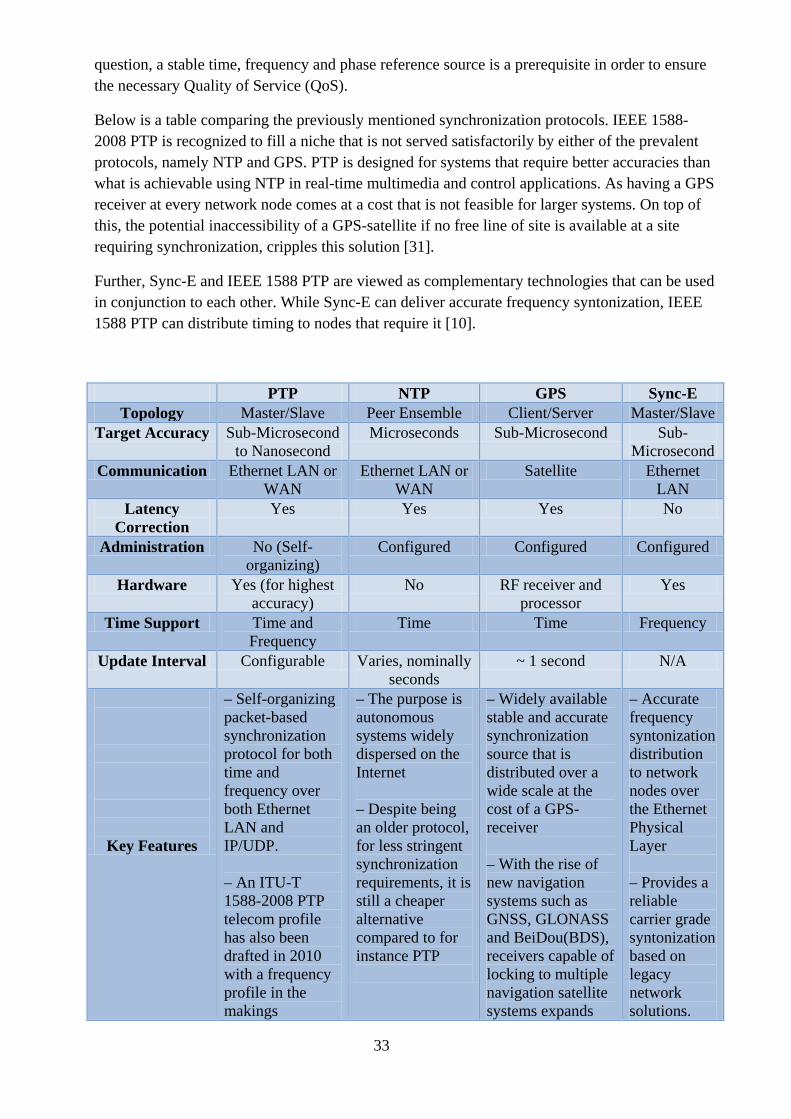
Below is a table comparing the previously mentioned synchronization protocols. IEEE 1588-2008 PTP is recognized to fill a niche that is not served satisfactorily by either of the prevalent protocols, namely NTP and GPS. PTP is designed for systems that require better accuracies than what is achievable using NTP in real-time multimedia and control applications. As having a GPS receiver at every network node comes at a cost that is not feasible for larger systems. On top of this, the potential inaccessibility of a GPS-satellite if no free line of site is available at a site requiring synchronization, cripples this solution [31].
Further, Sync-E and IEEE 1588 PTP are viewed as complementary technologies that can be used in conjunction to each other. While Sync-E can deliver accurate frequency syntonization, IEEE 1588 PTP can distribute timing to nodes that require it [10].
PTP NTP GPS Sync-E Topology Master/Slave Peer Ensemble Client/Server Master/Slave
Target Accuracy Sub-Microsecond to Nanosecond
Microseconds Sub-Microsecond Sub-Microsecond
Communication Ethernet LAN or WAN
Ethernet LAN or WAN
Satellite Ethernet LAN
Latency Correction
Yes Yes Yes No
Administration No (Self-organizing)
Configured Configured Configured
Hardware Yes (for highest accuracy)
No RF receiver and processor
Yes
Time Support Time and Frequency
Time Time Frequency
Update Interval Configurable Varies, nominally seconds
~ 1 second N/A
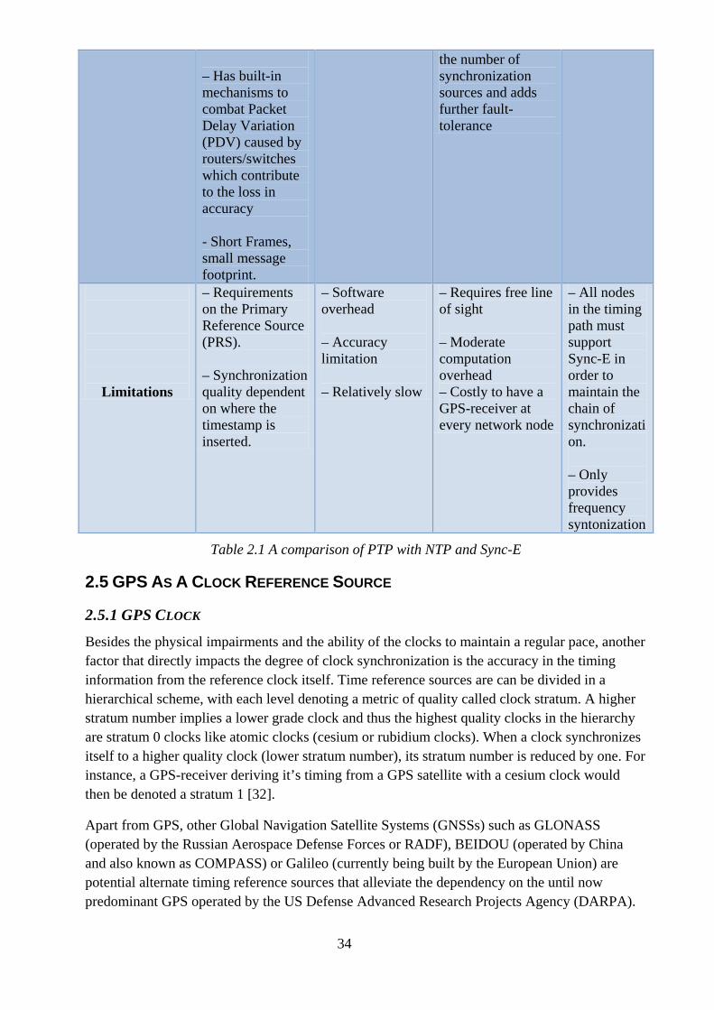
Key Features
– Self-organizing packet-based synchronization protocol for both time and frequency over both Ethernet LAN and IP/UDP. – An ITU-T 1588-2008 PTP telecom profile has also been drafted in 2010 with a frequency profile in the makings
– The purpose is autonomous systems widely dispersed on the Internet – Despite being an older protocol, for less stringent synchronization requirements, it is still a cheaper alternative compared to for instance PTP
– Widely available stable and accurate synchronization source that is distributed over a wide scale at the cost of a GPS-receiver – With the rise of new navigation systems such as GNSS, GLONASS and BeiDou(BDS), receivers capable of locking to multiple navigation satellite systems expands
– Accurate frequency syntonization distribution to network nodes over the Ethernet Physical Layer – Provides a reliable carrier grade syntonization based on legacy network solutions.
34
– Has built-in mechanisms to combat Packet Delay Variation (PDV) caused by routers/switches which contribute to the loss in accuracy - Short Frames, small message footprint.
the number of synchronization sources and adds further fault-tolerance
Limitations
– Requirements on the Primary Reference Source (PRS). – Synchronization quality dependent on where the timestamp is inserted.
– Software overhead
– Accuracy limitation – Relatively slow
– Requires free line of sight
– Moderate computation overhead – Costly to have a GPS-receiver at every network node
– All nodes in the timing path must support Sync-E in order to maintain the chain of synchronization. – Only provides frequency syntonization
Table 2.1 A comparison of PTP with NTP and Sync-E
2.5 GPS AS A CLOCK REFERENCE SOURCE
2.5.1 GPS CLOCK
Besides the physical impairments and the ability of the clocks to maintain a regular pace, another factor that directly impacts the degree of clock synchronization is the accuracy in the timing information from the reference clock itself. Time reference sources are can be divided in a hierarchical scheme, with each level denoting a metric of quality called clock stratum. A higher stratum number implies a lower grade clock and thus the highest quality clocks in the hierarchy are stratum 0 clocks like atomic clocks (cesium or rubidium clocks). When a clock synchronizes itself to a higher quality clock (lower stratum number), its stratum number is reduced by one. For instance, a GPS-receiver deriving it’s timing from a GPS satellite with a cesium clock would then be denoted a stratum 1 [32].
Apart from GPS, other Global Navigation Satellite Systems (GNSSs) such as GLONASS (operated by the Russian Aerospace Defense Forces or RADF), BEIDOU (operated by China and also known as COMPASS) or Galileo (currently being built by the European Union) are potential alternate timing reference sources that alleviate the dependency on the until now predominant GPS operated by the US Defense Advanced Research Projects Agency (DARPA).
35
GPS/GNSS signals are widely employed as low-cost highly precise time and frequency references that are used by distributed wireless communication, financial, industrial and power distribution systems. In the case of wireless communication standards that use Time Division Multiplexing (TDM) and Code Division Multiple Access 2000 (CDMA2000) (femtocell base stations) a precise reference source is vital. For such systems GPS/GNSS signals can be used to provide an accurate reference to within 1 part per 100 billion (1011) [33].
2.5.2 NMEA SENTENCES
The National Marine Electronics Association (NMEA) standard is a combined electrical interface and data protocol used for communication between marine instrumentation such as echo sounder, sonars, autopilots and GPS-receivers [34]. NMEA comes in various standards, including the NMEA 2000, 0400 and 0183. The latter being the one followed in this thesis. In the NMEA 0183 standard, all the characters that are included and used are printable ASCII text. NMEA-0183 data is transmitted over a serial data bus in the form of pre-specified sentences at a baud rate of 4800. Each sentence starts with a “$” sign followed by a number of data fields separated by commas. These data fields include information such as GPS fix, latitude, longitude, time (in UTC), date, number of satellites visible and azimuth in degrees only to mention some [34]. The standard is intended to function as a one-way serial data stream with one transmitter to one or more receivers or listeners.
An NMEA frame comprised of several sentences is shown below:
07:49:46 $GPRMC,074946.00,A,5924.21431,N,01756.84440,E,0.137,,140414,,,A*7F
07:49:46 $GPVTG,,T,,M,0.137,N,0.253,K,A*22
07:49:46 $GPGGA,074946.00,5924.21431,N,01756.84440,E,1,08,1.00,55.7,M,24.4,M,,*6E
07:49:46 $GPGSA,A,3,23,04,13,20,10,29,02,07,,,,,1.72,1.00,1.40*08
07:49:46 $GPGSV,4,1,16,02,35,299,44,04,42,237,27,05,01,300,,07,26,185,16*73
07:49:46 $GPGSV,4,2,16,08,01,194,17,10,53,281,45,13,81,195,08,16,20,088,*7D
07:49:46 $GPGSV,4,3,16,20,17,133,20,23,56,087,13,29,10,358,28,30,02,196,18*79
07:49:46 $GPGSV,4,4,16,31,03,034,,33,17,217,,39,22,172,,40,16,139,*7C
07:49:46 $GPGLL,5924.21431,N,01756.84440,E,074946.00,A,A*67
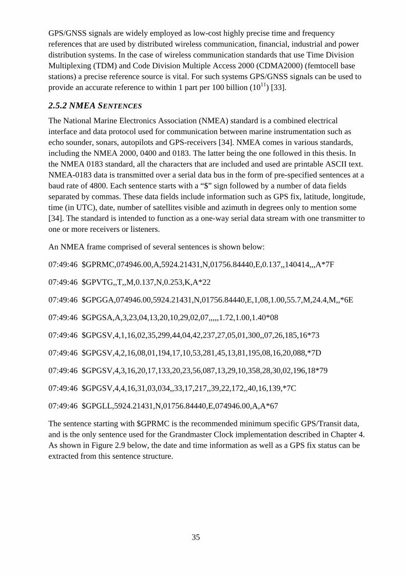
The sentence starting with $GPRMC is the recommended minimum specific GPS/Transit data, and is the only sentence used for the Grandmaster Clock implementation described in Chapter 4. As shown in Figure 2.9 below, the date and time information as well as a GPS fix status can be extracted from this sentence structure.
36
Figure 2.14: A GPRMC message with an explanation of what information each field contains.
2.6 RELATED WORK
2.6.1 HARDWARE REALIZATION OF IEEE 1588 SYNCHRONIZATION AND SYNTONIZATION FUNCTIONS [35]
Sven Meier, Hans Weibel and Karl Weber have implemented an IEEE 1588 clock that achieves synchronization and syntonization features entirely in hardware. The implementation is comprised of a three-port bridge with peer-to-peer Transparent Clock (TC) functionality along with an Ordinary Clock (OC) together with other application specific logic and protocol functions on an FPGA [35]. The purpose with their implementation is to provide a system clock with high accuracy and stability that can be driven with a simple crystal oscillator.
The functional blocks that deal with the communication and synchronization are mapped to the FPGA apart from the 100Base-T PHYs. These hardware functions include:
PTP Sync message generation that is sent at every nth cycle. The transmission rate is configurable with a theoretical maximum Sync rate of 32kHz.
Peer-delay request and response message functionality along with link delay calculation capability.
The TC enables the one-step mode in the Grandmaster by adding the link delay along with the residence times to the correction field in the Sync messages being transmitted.
The OC in the system synchronizes the local clock according to the received and corrected Sync messages. The frequency syntonization functionality is achieved using a PI regulator type servo loop.
A softcore processor is used to execute the applications and the higher layer protocol of the system.
The residence time is measured with a free-running clock (non-syntonized) whose error is considered negligible (0.1 ns per 50 parts per million frequency error). Whereas the clock attached OC maintains the system time and supports the application currently running at the node (Grandmaster or Slave Clock).
37
A Receive (RX)/Transmit (TX) Timestamp Unit (TSU) used to insert timestamps for incoming and outgoing packets between the MAC and PHY.
A timestamp buffer to process various PTP messages by their corresponding handlers. A correct startup behavior and exception handler is also implemented in a block called
“Timer & Ctrl”. A Clock Correction block that corrects the synchronous clock with a calculated drift and
offset correction. A delay handler that coordinates peer-to-peer delay measurement and determines the path
link delay to the next connected neighboring node on the uplink. If the system is in Grandmaster mode, the sync handler generates PTP Sync messages. If
it is in Slave mode, it calculates the drift and offset. A frame-parsing block that parses all incoming and outgoing traffic in order to detect
PTP messages. It extracts the necessary fields from these messages for further processing according to the PTP.
A frame generator responsible for Delay_Req, Delay_Resp and Sync messages based on static and dynamic values.
A Mailbox to interface the internal switch. A Correction Unit implements the TC functionality, including on-the-fly timestamp
insertion in PTP Sync messages when working in Grandmaster Mode.
System parameters such as Sync interval and Delay_Req interval are configurable externally by writing to certain registers.
Although the implementation differs from that of the one designed in this particular thesis (as the thesis deals with a Grandmaster-only Clock without Slave Clock capability), it provides an insight into the design methodology in terms of functionalities that are deemed necessary in a PTP Grandmaster capable Ordinary Clock. The implementation consists of a cheap 50 MHz clock with a 50 Parts Per Million (PPM) error, quite similar to the one used in the implementation of this thesis (See 4.1.1).
Their test environment consisted of three nodes that were able to cope with rapidly changing environmental conditions such as temperature. The Slave nodes did not exhibit any more deviation apart from the jitter caused by quantization error in the timestamp (±10ns due to 50 MHz clock). A freeze spray was used to cool the Grandmaster node’s oscillator and observe the response on the Slave node.
2.6.2 FREQUENCY COMPENSATED HARDWARE IEEE-1588 IMPLEMENTATION [36]
Teodor Neagoe, Maher Hamdi and Valentin Cristea have implemented hardware-assisted IEEE-1588 system on an Altera FPGA with direct control of the processor clock. The target is a homogeneous Ethernet LANs with applications such as control systems, automation, test and instrumentation along with telecommunications [36].
An evaluation of design choices in terms of what functionality should be mapped to software versus hardware is also conducted as part of their study. It is noted that when implemented in software, the entire protocol is executed at the application level. This includes the processing of the timestamps and control of the clock (referred to as the Real Time Clock or RTC). As
38
mentioned in section 2.2.2, this option yields the least accuracy due to the variations in the protocol network in the lower layers.
As the timestamping point is moved closer to the physical layer, accuracies are noted to improve from hundreds of microseconds down to the order of hundreds of nanoseconds. A hardware-assisted software implementation of the IEEE-1588 protocol with a Time Stamp Unit (TSU) that is responsible for inserting and extracting timestamps at the Media Independent Interface between the MAC and PHY from IEEE-1588 packets. The timestamps are exchanged with protocol task via an interface with the processor.
A Hardware Real Time Clock (HW-RTC) is initialized by the operating system and kept updated by the IEEE-1588 software, however it increments its counter independently using the hardware clock of the processor. It is noted that similar implementations to this by Agilent Technologies have observed synchronization levels within ±20 ns.
The proposed frequency compensated IEEE-1588 implementation uses hardware to control the processor frequency clock based on the PTP Sync message transmitted. The idea is an extension of the implementation mentioned in the previous paragraph, however with an additional hardware block called the Frequency Control Unit (FCU). The Frequency Control Unit adjusts the slave processor clock in order to maintain the period between two consecutive Sync messages within a tolerated error level.
Both a Grandmaster and a Slave Clock were implemented on two similar Altera FPGA evaluation boards. The measured levels of synchronization using the frequency compensated clock method gave results in the order of 10-20 ns. As a conclusion the following advantages have been observed from the proposed implementation:
By having Slave and Grandmaster clocks synchronized to each other, allows for real-time transmission of time critical payload as well as easier time updates.
As the MAC used in the implementation was Intellectual Property (IP) core, the TSU is able to access to its internal registers and thus is able to insert timestamps on-the-fly from the HW-RTC. Hence, a one-step clock mode can be used and no Sync Follow-Up message is required.
The board’s triple speed MAC is ready for Gigabit Ethernet applications and can thus very easily be upgraded, eliminating the need for a complete redesign.
The frequency control is taken care of internally without the need for any external components.
Once the Grandmaster and Slave is synchronized, the Sync message transmission rate can be reduced to a level that is sufficient to maintain the Slave clock’s crystal oscillator stability. It is also suggested that Delay_Req and Delay_Response messages can be ignored at once synchronization has been achieved.
The frequency compensated clock method presented here is a simple and accurate implementation of the IEEE-1588 protocol in hardware on an FPGA. Despite not being a dedicated IEEE-1588 Grandmaster Clock using a GPS as its PRS, as is the case of the implementation in this thesis, it shares many common design elements and considerations that are required to systemize a system of this type.
39
3 IMPLEMENTATION
3.1 HARDWARE, DESIGN TOOLS AND ENVIRONMENT
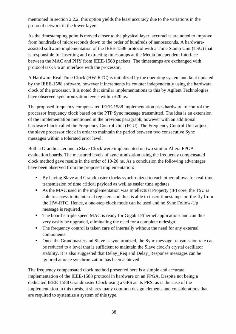
3.1.1 FPGA DEVELOPMENT BOARD A Xilinx Artix-7 XC7A200T FPGA on an AC701 evaluation board was used build the PTP Grandmaster Clock System. The Artix family of FPGAs is targeted for systems that require the lowest cost and power with smaller form factor in mind. The FPGA consists of 215K programmable Logic Cells. The development board also consists of an FMC connector (as shown in Figure 3.1), on which an expansion card with General Purpose Input Output (GPIO) pins to which various design ports can be mapped to [37].
Figure 3.1: Xilinx Artix -7 FPGA AC701 Evaluation Board used to map the Grandmaster Clock logic blocks on.
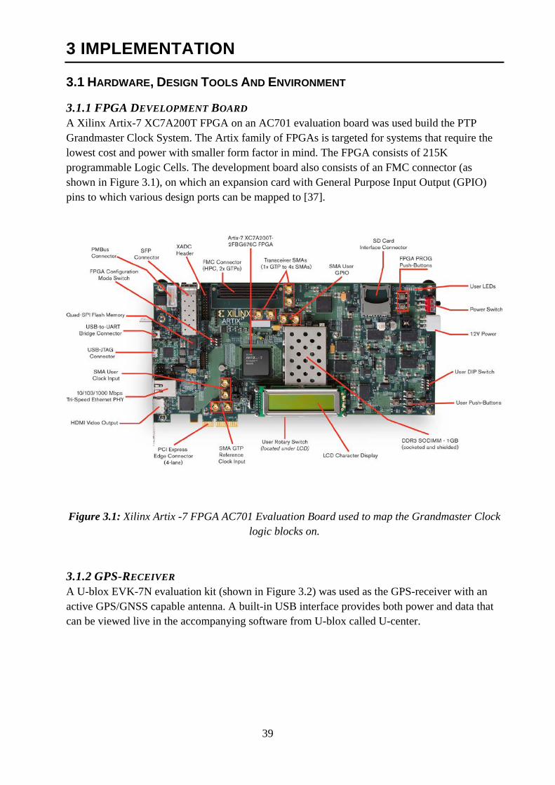
3.1.2 GPS-RECEIVER A U-blox EVK-7N evaluation kit (shown in Figure 3.2) was used as the GPS-receiver with an active GPS/GNSS capable antenna. A built-in USB interface provides both power and data that can be viewed live in the accompanying software from U-blox called U-center.
40
Figure 3.2: GPS/GNSS receiver from U-blox with the included active antenna.
The U-blox GPS-receiver also provides a serial RS2323 interface as well as a number of pins over which one is able to either use an Inter-Integrated Circuit (I2C) or Serial Peripheral Interface Bus (SPI). When used in SPI mode, using these pins one is able to extract NMEA packets as well as a 1 PPS signal. The NMEA packet stream is updated once per second.
U-center provides the user with an interactive tool for configuration, testing, visualization and data analysis of the GPS-receiver module.
An LED on the front panel indicates whether a GNSS fix has been established by blinking one pulse per second. When no fix is available the LED is lit solid.
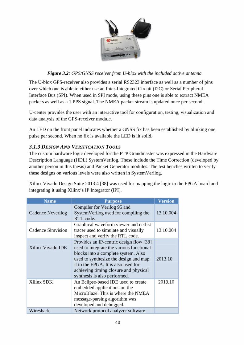
3.1.3 DESIGN AND VERIFICATION TOOLS The custom hardware logic developed for the PTP Grandmaster was expressed in the Hardware Description Language (HDL) SystemVerilog. These include the Time Correction (developed by another person in this thesis) and Packet Generator modules. The test benches written to verify these designs on various levels were also written in SystemVerilog.
Xilinx Vivado Design Suite 2013.4 [38] was used for mapping the logic to the FPGA board and integrating it using Xilinx’s IP Integrator (IPI).
Name Purpose Version Cadence Ncverilog
Compiler for Verilog 95 and SystemVerilog used for compiling the RTL code.
13.10.004
Cadence Simvision
Graphical waveform viewer and netlist tracer used to simulate and visually inspect and verify the RTL code.
13.10.004
Xilinx Vivado IDE
Provides an IP-centric design flow [38] used to integrate the various functional blocks into a complete system. Also used to synthesize the design and map it to the FPGA. It is also used for achieving timing closure and physical synthesis is also performed.
2013.10
Xilinx SDK An Eclipse-based IDE used to create embedded applications on the MicroBlaze. This is where the NMEA message-parsing algorithm was developed and debugged.
2013.10
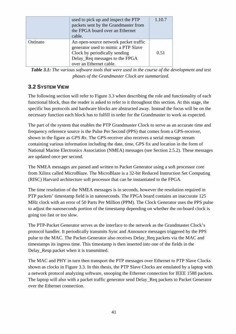
Wireshark Network protocol analyzer software
41
used to pick up and inspect the PTP packets sent by the Grandmaster from the FPGA board over an Ethernet cable.
1.10.7
Ostinato An open-source network packet traffic generator used to mimic a PTP Slave Clock by periodically sending Delay_Req messages to the FPGA over an Ethernet cable.
0.51
Table 3.1: The various software tools that were used in the course of the development and test phases of the Grandmaster Clock are summarized.
3.2 SYSTEM VIEW The following section will refer to Figure 3.3 when describing the role and functionality of each functional block, thus the reader is asked to refer to it throughout this section. At this stage, the specific bus protocols and hardware blocks are abstracted away. Instead the focus will be on the necessary function each block has to fulfill in order for the Grandmaster to work as expected.
The part of the system that enables the PTP Grandmaster Clock to serve as an accurate time and frequency reference source is the Pulse Per Second (PPS) that comes from a GPS-receiver, shown in the figure as GPS Rx. The GPS-receiver also receives a serial message stream containing various information including the date, time, GPS fix and location in the form of National Marine Electronics Association (NMEA) messages (see Section 2.5.2). These messages are updated once per second.
The NMEA messages are parsed and written to Packet Generator using a soft processor core from Xilinx called MicroBlaze. The MicroBlaze is a 32-bit Reduced Instruction Set Computing (RISC) Harvard architecture soft processor that can be instantiated to the FPGA.
The time resolution of the NMEA messages is in seconds, however the resolution required in PTP packets’ timestamp field is in nanoseconds. The FPGA board contains an inaccurate 125 MHz clock with an error of 50 Parts Per Million (PPM). The Clock Generator uses the PPS pulse to adjust the nanoseconds portion of the timestamp depending on whether the on-board clock is going too fast or too slow.
The PTP-Packet Generator serves as the interface to the network as the Grandmaster Clock’s protocol handler. It periodically transmits Sync and Announce messages triggered by the PPS pulse to the MAC. The Packet-Generator also receives Delay_Req packets via the MAC and timestamps its ingress time. This timestamp is then inserted into one of the fields in the Delay_Resp packet when it is transmitted.
The MAC and PHY in turn then transport the PTP messages over Ethernet to PTP Slave Clocks shown as clocks in Figure 3.3. In this thesis, the PTP Slave Clocks are emulated by a laptop with a network protocol analyzing software, snooping the Ethernet connection for IEEE 1588 packets. The laptop will also with a packet traffic generator send Delay_Req packets to Packet Generator over the Ethernet connection.
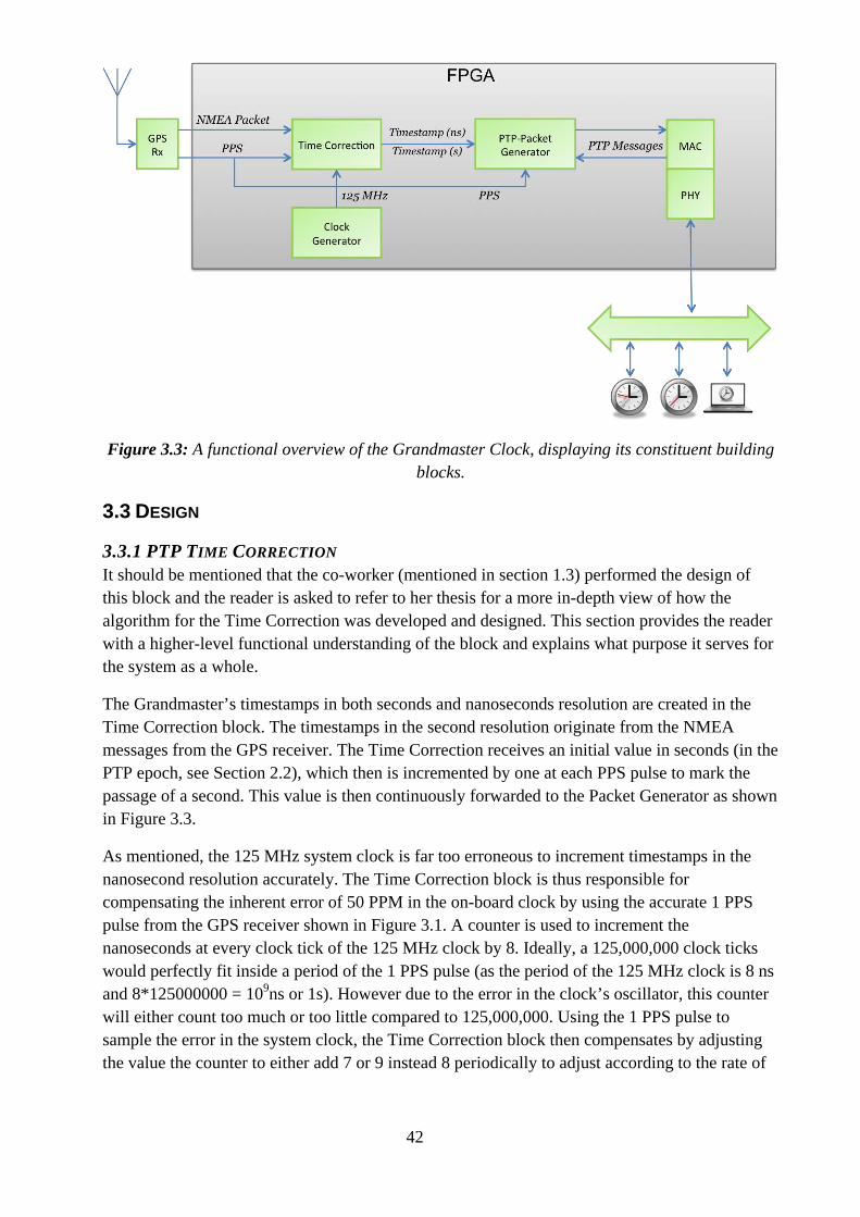
42
Figure 3.3: A functional overview of the Grandmaster Clock, displaying its constituent building blocks.
3.3 DESIGN
3.3.1 PTP TIME CORRECTION It should be mentioned that the co-worker (mentioned in section 1.3) performed the design of this block and the reader is asked to refer to her thesis for a more in-depth view of how the algorithm for the Time Correction was developed and designed. This section provides the reader with a higher-level functional understanding of the block and explains what purpose it serves for the system as a whole.
The Grandmaster’s timestamps in both seconds and nanoseconds resolution are created in the Time Correction block. The timestamps in the second resolution originate from the NMEA messages from the GPS receiver. The Time Correction receives an initial value in seconds (in the PTP epoch, see Section 2.2), which then is incremented by one at each PPS pulse to mark the passage of a second. This value is then continuously forwarded to the Packet Generator as shown in Figure 3.3.
As mentioned, the 125 MHz system clock is far too erroneous to increment timestamps in the nanosecond resolution accurately. The Time Correction block is thus responsible for compensating the inherent error of 50 PPM in the on-board clock by using the accurate 1 PPS pulse from the GPS receiver shown in Figure 3.1. A counter is used to increment the nanoseconds at every clock tick of the 125 MHz clock by 8. Ideally, a 125,000,000 clock ticks would perfectly fit inside a period of the 1 PPS pulse (as the period of the 125 MHz clock is 8 ns and 8*125000000 = 109ns or 1s). However due to the error in the clock’s oscillator, this counter will either count too much or too little compared to 125,000,000. Using the 1 PPS pulse to sample the error in the system clock, the Time Correction block then compensates by adjusting the value the counter to either add 7 or 9 instead 8 periodically to adjust according to the rate of
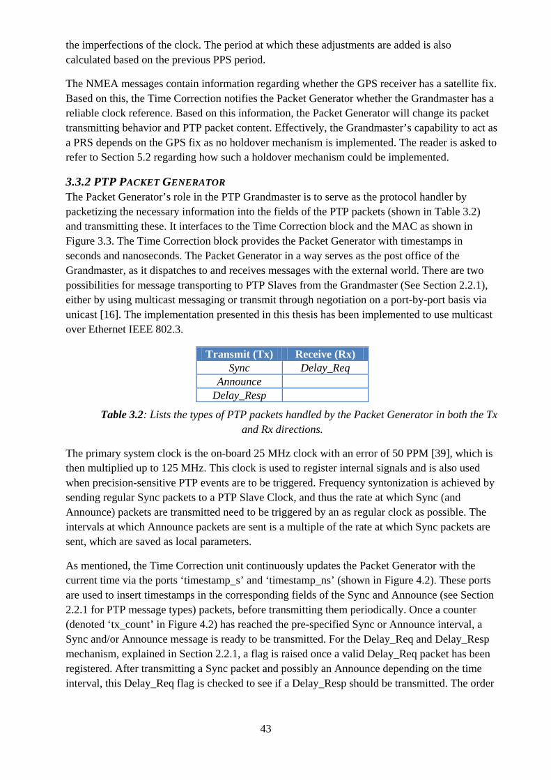
43
the imperfections of the clock. The period at which these adjustments are added is also calculated based on the previous PPS period.
The NMEA messages contain information regarding whether the GPS receiver has a satellite fix. Based on this, the Time Correction notifies the Packet Generator whether the Grandmaster has a reliable clock reference. Based on this information, the Packet Generator will change its packet transmitting behavior and PTP packet content. Effectively, the Grandmaster’s capability to act as a PRS depends on the GPS fix as no holdover mechanism is implemented. The reader is asked to refer to Section 5.2 regarding how such a holdover mechanism could be implemented.
3.3.2 PTP PACKET GENERATOR The Packet Generator’s role in the PTP Grandmaster is to serve as the protocol handler by packetizing the necessary information into the fields of the PTP packets (shown in Table 3.2) and transmitting these. It interfaces to the Time Correction block and the MAC as shown in Figure 3.3. The Time Correction block provides the Packet Generator with timestamps in seconds and nanoseconds. The Packet Generator in a way serves as the post office of the Grandmaster, as it dispatches to and receives messages with the external world. There are two possibilities for message transporting to PTP Slaves from the Grandmaster (See Section 2.2.1), either by using multicast messaging or transmit through negotiation on a port-by-port basis via unicast [16]. The implementation presented in this thesis has been implemented to use multicast over Ethernet IEEE 802.3.
Transmit (Tx) Receive (Rx) Sync Delay_Req
Announce Delay_Resp
Table 3.2: Lists the types of PTP packets handled by the Packet Generator in both the Tx and Rx directions.
The primary system clock is the on-board 25 MHz clock with an error of 50 PPM [39], which is then multiplied up to 125 MHz. This clock is used to register internal signals and is also used when precision-sensitive PTP events are to be triggered. Frequency syntonization is achieved by sending regular Sync packets to a PTP Slave Clock, and thus the rate at which Sync (and Announce) packets are transmitted need to be triggered by an as regular clock as possible. The intervals at which Announce packets are sent is a multiple of the rate at which Sync packets are sent, which are saved as local parameters.
As mentioned, the Time Correction unit continuously updates the Packet Generator with the current time via the ports ‘timestamp_s’ and ‘timestamp_ns’ (shown in Figure 4.2). These ports are used to insert timestamps in the corresponding fields of the Sync and Announce (see Section 2.2.1 for PTP message types) packets, before transmitting them periodically. Once a counter (denoted ‘tx_count’ in Figure 4.2) has reached the pre-specified Sync or Announce interval, a Sync and/or Announce message is ready to be transmitted. For the Delay_Req and Delay_Resp mechanism, explained in Section 2.2.1, a flag is raised once a valid Delay_Req packet has been registered. After transmitting a Sync packet and possibly an Announce depending on the time interval, this Delay_Req flag is checked to see if a Delay_Resp should be transmitted. The order
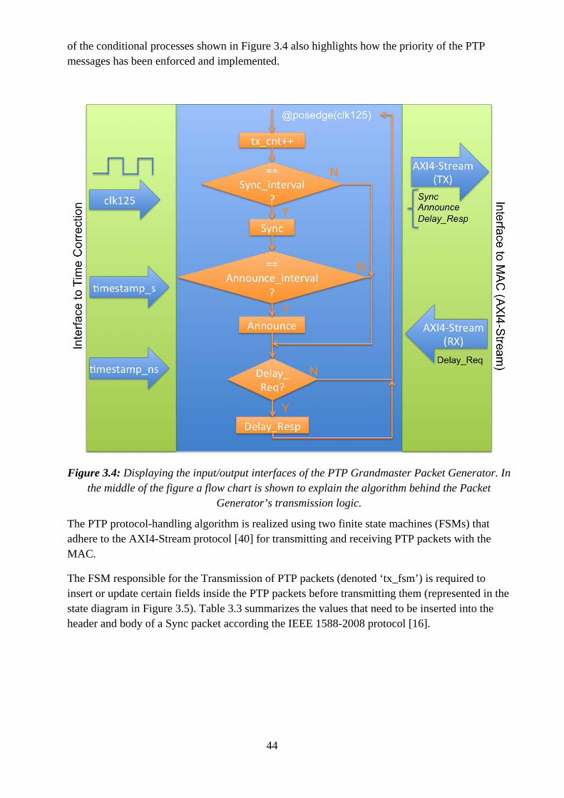
44
of the conditional processes shown in Figure 3.4 also highlights how the priority of the PTP messages has been enforced and implemented.
Figure 3.4: Displaying the input/output interfaces of the PTP Grandmaster Packet Generator. In the middle of the figure a flow chart is shown to explain the algorithm behind the Packet
Generator’s transmission logic.
The PTP protocol-handling algorithm is realized using two finite state machines (FSMs) that adhere to the AXI4-Stream protocol [40] for transmitting and receiving PTP packets with the MAC.
The FSM responsible for the Transmission of PTP packets (denoted ‘tx_fsm’) is required to insert or update certain fields inside the PTP packets before transmitting them (represented in the state diagram in Figure 3.5). Table 3.3 summarizes the values that need to be inserted into the header and body of a Sync packet according the IEEE 1588-2008 protocol [16].
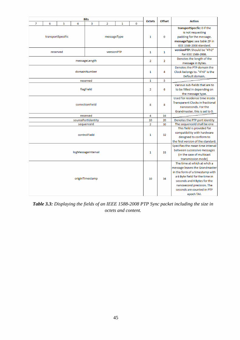
45
Table 3.3: Displaying the fields of an IEEE 1588-2008 PTP Sync packet including the size in octets and content.
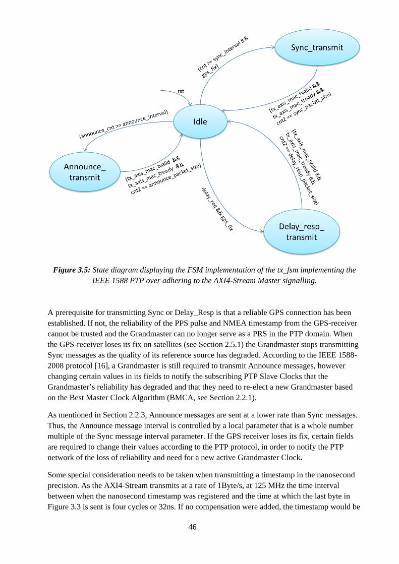
46
Figure 3.5: State diagram displaying the FSM implementation of the tx_fsm implementing the IEEE 1588 PTP over adhering to the AXI4-Stream Master signalling.
A prerequisite for transmitting Sync or Delay_Resp is that a reliable GPS connection has been established. If not, the reliability of the PPS pulse and NMEA timestamp from the GPS-receiver cannot be trusted and the Grandmaster can no longer serve as a PRS in the PTP domain. When the GPS-receiver loses its fix on satellites (see Section 2.5.1) the Grandmaster stops transmitting Sync messages as the quality of its reference source has degraded. According to the IEEE 1588-2008 protocol [16], a Grandmaster is still required to transmit Announce messages, however changing certain values in its fields to notify the subscribing PTP Slave Clocks that the Grandmaster’s reliability has degraded and that they need to re-elect a new Grandmaster based on the Best Master Clock Algorithm (BMCA, see Section 2.2.1).
As mentioned in Section 2.2.3, Announce messages are sent at a lower rate than Sync messages. Thus, the Announce message interval is controlled by a local parameter that is a whole number multiple of the Sync message interval parameter. If the GPS receiver loses its fix, certain fields are required to change their values according to the PTP protocol, in order to notify the PTP network of the loss of reliability and need for a new active Grandmaster Clock.
Some special consideration needs to be taken when transmitting a timestamp in the nanosecond precision. As the AXI4-Stream transmits at a rate of 1Byte/s, at 125 MHz the time interval between when the nanosecond timestamp was registered and the time at which the last byte in Figure 3.3 is sent is four cycles or 32ns. If no compensation were added, the timestamp would be
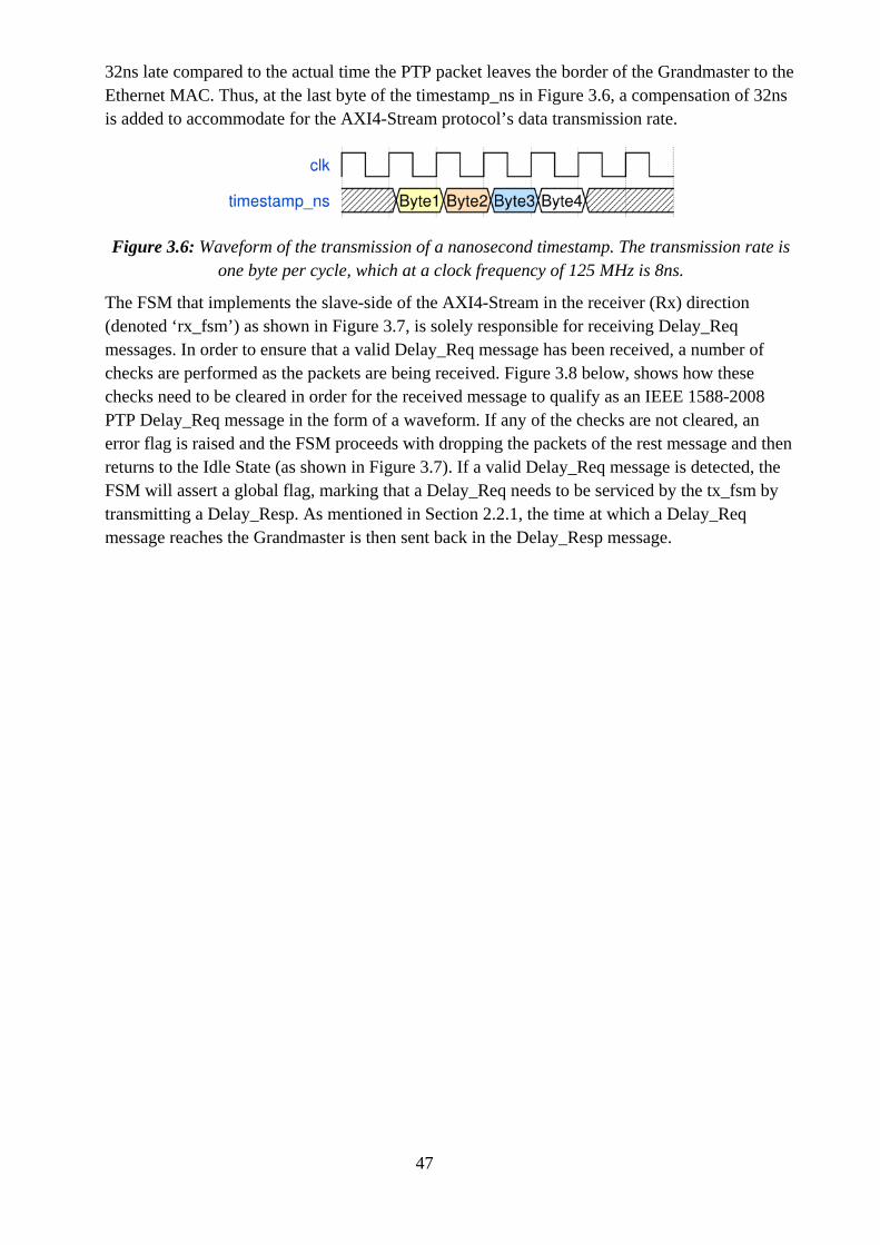
47
32ns late compared to the actual time the PTP packet leaves the border of the Grandmaster to the Ethernet MAC. Thus, at the last byte of the timestamp_ns in Figure 3.6, a compensation of 32ns is added to accommodate for the AXI4-Stream protocol’s data transmission rate.
Figure 3.6: Waveform of the transmission of a nanosecond timestamp. The transmission rate is one byte per cycle, which at a clock frequency of 125 MHz is 8ns.
The FSM that implements the slave-side of the AXI4-Stream in the receiver (Rx) direction (denoted ‘rx_fsm’) as shown in Figure 3.7, is solely responsible for receiving Delay_Req messages. In order to ensure that a valid Delay_Req message has been received, a number of checks are performed as the packets are being received. Figure 3.8 below, shows how these checks need to be cleared in order for the received message to qualify as an IEEE 1588-2008 PTP Delay_Req message in the form of a waveform. If any of the checks are not cleared, an error flag is raised and the FSM proceeds with dropping the packets of the rest message and then returns to the Idle State (as shown in Figure 3.7). If a valid Delay_Req message is detected, the FSM will assert a global flag, marking that a Delay_Req needs to be serviced by the tx_fsm by transmitting a Delay_Resp. As mentioned in Section 2.2.1, the time at which a Delay_Req message reaches the Grandmaster is then sent back in the Delay_Resp message.
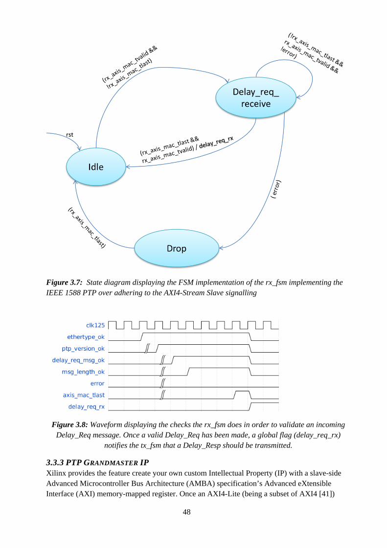
48
Figure 3.7: State diagram displaying the FSM implementation of the rx_fsm implementing the IEEE 1588 PTP over adhering to the AXI4-Stream Slave signalling
Figure 3.8: Waveform displaying the checks the rx_fsm does in order to validate an incoming Delay_Req message. Once a valid Delay_Req has been made, a global flag (delay_req_rx)
notifies the tx_fsm that a Delay_Resp should be transmitted.
3.3.3 PTP GRANDMASTER IP Xilinx provides the feature create your own custom Intellectual Property (IP) with a slave-side Advanced Microcontroller Bus Architecture (AMBA) specification’s Advanced eXtensible Interface (AXI) memory-mapped register. Once an AXI4-Lite (being a subset of AXI4 [41])
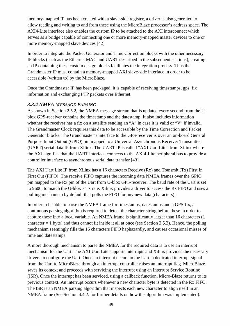
49
memory-mapped IP has been created with a slave-side register, a driver is also generated to allow reading and writing to and from these using the MicroBlaze processor’s address space. The AXI4-Lite interface also enables the custom IP to be attached to the AXI interconnect which serves as a bridge capable of connecting one or more memory-mapped master devices to one or more memory-mapped slave devices [42].
In order to integrate the Packet Generator and Time Correction blocks with the other necessary IP blocks (such as the Ethernet MAC and UART described in the subsequent sections), creating an IP containing these custom design blocks facilitates the integration process. Thus the Grandmaster IP must contain a memory-mapped AXI slave-side interface in order to be accessible (written to) by the MicroBlaze.
Once the Grandmaster IP has been packaged, it is capable of receiving timestamps, gps_fix information and exchanging PTP packets over Ethernet.
3.3.4 NMEA MESSAGE PARSING As shown in Section 2.5.2, the NMEA message stream that is updated every second from the U-blox GPS-receiver contains the timestamp and the datestamp. It also includes information whether the receiver has a fix on a satellite sending an “A” in case it is valid or “V” if invalid. The Grandmaster Clock requires this data to be accessible by the Time Correction and Packet Generator blocks. The Grandmaster’s interface to the GPS-receiver is over an on-board General Purpose Input Output (GPIO) pin mapped to a Universal Asynchronous Receiver Transmitter (UART) serial data IP from Xilinx. The UART IP is called “AXI Uart Lite” from Xilinx where the AXI signifies that the UART interface connects to the AXI4-Lite peripheral bus to provide a controller interface to asynchronous serial data transfer [43].
The AXI Uart Lite IP from Xilinx has a 16 characters Receive (Rx) and Transmit (Tx) First In First Out (FIFO). The receive FIFO captures the incoming data NMEA frames over the GPIO pin mapped to the Rx pin of the Uart from U-blox GPS-receiver. The baud rate of the Uart is set to 9600, to match the U-blox’s Tx rate. Xilinx provides a driver to access the Rx FIFO and uses a polling mechanism by default that polls the FIFO for any new data (characters).
In order to be able to parse the NMEA frame for timestamps, datestamps and a GPS-fix, a continuous parsing algorithm is required to detect the character string before these in order to capture these into a local variable. An NMEA frame is significantly larger than 16 characters (1 character = 1 byte) and thus cannot fit inside it all at once (see Section 2.5.2). Hence, the polling mechanism seemingly fills the 16 characters FIFO haphazardly, and causes occasional misses of time and datestamps.
A more thorough mechanism to parse the NMEA for the required data is to use an interrupt mechanism for the Uart. The AXI Uart Lite supports interrupts and Xilinx provides the necessary drivers to configure the Uart. Once an interrupt occurs in the Uart, a dedicated interrupt signal from the Uart to MicroBlaze through an interrupt controller raises an interrupt flag. MicroBlaze saves its context and proceeds with servicing the interrupt using an Interrupt Service Routine (ISR). Once the interrupt has been serviced, using a callback function, Micro-Blaze returns to its previous context. An interrupt occurs whenever a new character byte is detected in the Rx FIFO. The ISR is an NMEA parsing algorithm that inspects each new character to align itself in an NMEA frame (See Section 4.4.2. for further details on how the algorithm was implemented).
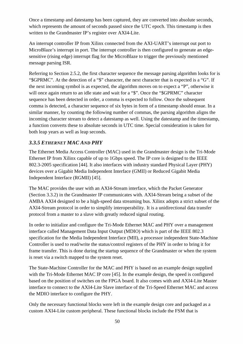
50
Once a timestamp and datestamp has been captured, they are converted into absolute seconds, which represents the amount of seconds passed since the UTC epoch. This timestamp is then written to the Grandmaster IP’s register over AXI4-Lite.
An interrupt controller IP from Xilinx connected from the AXI-UART’s interrupt out port to MicroBlaze’s interrupt in port. The interrupt controller is then configured to generate an edge-sensitive (rising edge) interrupt flag for the MicroBlaze to trigger the previously mentioned message parsing ISR.
Referring to Section 2.5.2, the first character sequence the message parsing algorithm looks for is “$GPRMC”. At the detection of a “$” character, the next character that is expected is a “G”. If the next incoming symbol is as expected, the algorithm moves on to expect a “P”, otherwise it will once again return to an idle state and wait for a “$”. Once the “$GPRMC” character sequence has been detected in order, a comma is expected to follow. Once the subsequent comma is detected, a character sequence of six bytes in form of a timestamp should ensue. In a similar manner, by counting the following number of commas, the parsing algorithm aligns the incoming character stream to detect a datestamp as well. Using the datestamp and the timestamp, a function converts these to absolute seconds in UTC time. Special consideration is taken for both leap years as well as leap seconds.
3.3.5 ETHERNET MAC AND PHY
The Ethernet Media Access Controller (MAC) used in the Grandmaster design is the Tri-Mode Ethernet IP from Xilinx capable of up to 1Gbps speed. The IP core is designed to the IEEE 802.3-2005 specification [44]. It also interfaces with industry standard Physical Layer (PHY) devices over a Gigabit Media Independent Interface (GMII) or Reduced Gigabit Media Independent Interface (RGMII) [45].
The MAC provides the user with an AXI4-Stream interface, which the Packet Generator (Section 3.3.2) in the Grandmaster IP communicates with. AXI4-Stream being a subset of the AMBA AXI4 designed to be a high-speed data streaming bus. Xilinx adopts a strict subset of the AXI4-Stream protocol in order to simplify interoperability. It is a unidirectional data transfer protocol from a master to a slave with greatly reduced signal routing.
In order to initialize and configure the Tri-Mode Ethernet MAC and PHY over a management interface called Management Data Input Output (MDIO) which is part of the IEEE 802.3 specification for the Media Independent Interface (MII), a processor independent State-Machine Controller is used to read/write the status/control registers of the PHY in order to bring it for frame transfer. This is done during the startup sequence of the Grandmaster or when the system is reset via a switch mapped to the system reset.
The State-Machine Controller for the MAC and PHY is based on an example design supplied with the Tri-Mode Ethernet MAC IP core [45]. In the example design, the speed is configured based on the position of switches on the FPGA board. It also comes with and AXI4-Lite Master interface to connect to the AXI4-Lite Slave interface of the Tri-Speed Ethernet MAC and access the MDIO interface to configure the PHY.
Only the necessary functional blocks were left in the example design core and packaged as a custom AXI4-Lite custom peripheral. These functional blocks include the FSM that is
51
responsible for bringing up the MAC/PHY and the clock and reset logic blocks. The transfer speed control that was mapped to the switches was hard-coded to be set to 1Gbps by default.
3.4 VERIFICATION The verification of the Grandmaster Clock was performed at various levels and was, depending on the part of the system, performed by two different people either separately or together. These levels include individual RTL modules expressed in SystemVerilog, all the way to the entire Grandmaster Clock IP, which is comprised of the Time Correction and Packet Generator modules as well as the necessary AXI4-Lite Slave interface to act as a memory mapped peripheral to the MicroBlaze for data writes containing time, date and GPS-fix information from the UART.
3.4.1 PACKET GENERATOR
As the author of this thesis designed the Packet Generator, the co-designer responsible for the Time Correction module verified it. This delegation was chosen as a verification strategy in order to minimize the risk of the designer having to verify his own design and thus, as is common in such cases, being blind to his own mistakes and design bugs. A more thorough discussion regarding the verification methodology employed for the packet generator is discussed in the co-designer’s thesis.
A sanity-check level of verification was however performed by the designer of the Packet Generator. This included matching the timing of the fields of the PTP packets and the required data that was required to be available in the correct clock cycle. A basic test-bench that sent stimuli in the form of periodic Delay_Req messages to the Packet Generator was created. The same test-bench also captured the periodic Sync, Delay_Req and Announce messages that could be visually inspected in Cadence Simvision’s simulation environment.
3.4.2 GRANDMASTER IP
The Grandmaster IP also required verification at the RTL level, which included the previously mentioned stimuli for the Packet Generator as well as a timestamp and gps_fix that is written to the AXI4-Lite Slave interface. The timestamp is sent to the Time Correction block via dedicated ports (with flags indicating whenever data has been written to them) to the internal registers in the AXI4-Lite interface. This is also the case for the gps_fix flag that (as mentioned in section 3.3.2) should trigger the Packet Generator to stop sending Sync and responding to Delay_Req messages. It is also required change the contents of the Announce message that the Grandmaster transmits periodically, by notifying the currently subscribed PTP Slave Clocks that the Grandmaster has lost its reliability and should be degraded in stratum level when employing the Best Master Clock Algorithm (BMCA) (which is used to evaluate the currently best suitable Grandmaster Clock with within a PTP domain).
The Grandmaster IP also interfaces the Tri-Speed Ethernet MAC from Xilinx over AXI4-Stream as both a Master and Slave interface. In order to verify the interfaces’ functionality, a corresponding interface is required from the test-bench. Hence the test-bench implemented the AXI4-Stream protocol in order to mimic the environment the Grandmaster IP would interface once it was combined with the MAC IP.
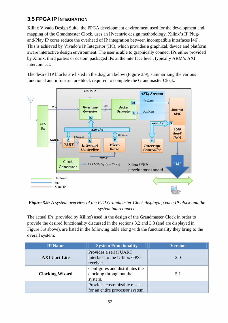
52
3.5 FPGA IP INTEGRATION Xilinx Vivado Design Suite, the FPGA development environment used for the development and mapping of the Grandmaster Clock, uses an IP-centric design methodology. Xilinx’s IP Plug-and-Play IP cores reduce the overhead of IP integration between incompatible interfaces [46]. This is achieved by Vivado’s IP Integrator (IPI), which provides a graphical, device and platform aware interactive design environment. The user is able to graphically connect IPs either provided by Xilinx, third parties or custom packaged IPs at the interface level, typically ARM’s AXI interconnect.
The desired IP blocks are listed in the diagram below (Figure 3.9), summarizing the various functional and infrastructure block required to complete the Grandmaster Clock.
Figure 3.9: A system overview of the PTP Grandmaster Clock displaying each IP block and the system interconnect.
The actual IPs (provided by Xilinx) used in the design of the Grandmaster Clock in order to provide the desired functionality discussed in the sections 3.2 and 3.3 (and are displayed in Figure 3.9 above), are listed in the following table along with the functionality they bring to the overall system:
IP Name System Functionality Version
AXI Uart Lite Provides a serial UART interface to the U-blox GPS-receiver.
2.0
Clocking Wizard
Configures and distributes the clocking throughout the system.
5.1
Provides customizable resets for an entire processor system,
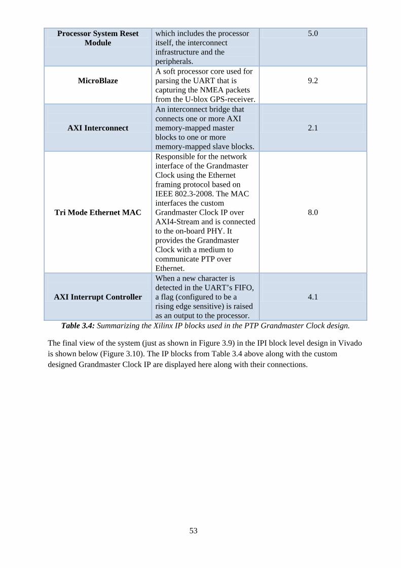
53
Processor System Reset Module
which includes the processor itself, the interconnect infrastructure and the peripherals.
5.0
MicroBlaze
A soft processor core used for parsing the UART that is capturing the NMEA packets from the U-blox GPS-receiver.
9.2
AXI Interconnect
An interconnect bridge that connects one or more AXI memory-mapped master blocks to one or more memory-mapped slave blocks.
2.1
Tri Mode Ethernet MAC
Responsible for the network interface of the Grandmaster Clock using the Ethernet framing protocol based on IEEE 802.3-2008. The MAC interfaces the custom Grandmaster Clock IP over AXI4-Stream and is connected to the on-board PHY. It provides the Grandmaster Clock with a medium to communicate PTP over Ethernet.
8.0
AXI Interrupt Controller
When a new character is detected in the UART’s FIFO, a flag (configured to be a rising edge sensitive) is raised as an output to the processor.
4.1
Table 3.4: Summarizing the Xilinx IP blocks used in the PTP Grandmaster Clock design.
The final view of the system (just as shown in Figure 3.9) in the IPI block level design in Vivado is shown below (Figure 3.10). The IP blocks from Table 3.4 above along with the custom designed Grandmaster Clock IP are displayed here along with their connections.
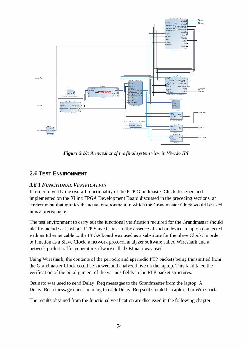
54
Figure 3.10: A snapshot of the final system view in Vivado IPI.
3.6 TEST ENVIRONMENT
3.6.1 FUNCTIONAL VERIFICATION In order to verify the overall functionality of the PTP Grandmaster Clock designed and implemented on the Xilinx FPGA Development Board discussed in the preceding sections, an environment that mimics the actual environment in which the Grandmaster Clock would be used in is a prerequisite.
The test environment to carry out the functional verification required for the Grandmaster should ideally include at least one PTP Slave Clock. In the absence of such a device, a laptop connected with an Ethernet cable to the FPGA board was used as a substitute for the Slave Clock. In order to function as a Slave Clock, a network protocol analyzer software called Wireshark and a network packet traffic generator software called Ostinato was used.
Using Wireshark, the contents of the periodic and aperiodic PTP packets being transmitted from the Grandmaster Clock could be viewed and analyzed live on the laptop. This facilitated the verification of the bit alignment of the various fields in the PTP packet structures.
Ostinato was used to send Delay_Req messages to the Grandmaster from the laptop. A Delay_Resp message corresponding to each Delay_Req sent should be captured in Wireshark.
The results obtained from the functional verification are discussed in the following chapter.
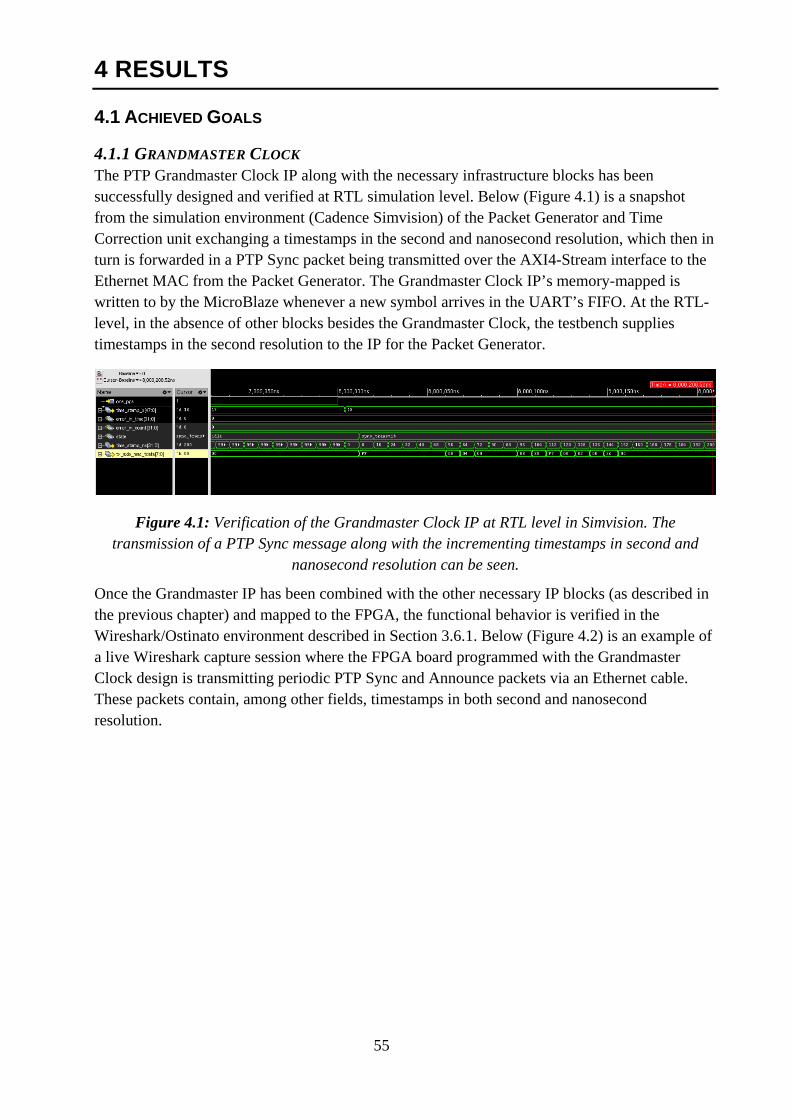
55
4 RESULTS
4.1 ACHIEVED GOALS
4.1.1 GRANDMASTER CLOCK The PTP Grandmaster Clock IP along with the necessary infrastructure blocks has been successfully designed and verified at RTL simulation level. Below (Figure 4.1) is a snapshot from the simulation environment (Cadence Simvision) of the Packet Generator and Time Correction unit exchanging a timestamps in the second and nanosecond resolution, which then in turn is forwarded in a PTP Sync packet being transmitted over the AXI4-Stream interface to the Ethernet MAC from the Packet Generator. The Grandmaster Clock IP’s memory-mapped is written to by the MicroBlaze whenever a new symbol arrives in the UART’s FIFO. At the RTL-level, in the absence of other blocks besides the Grandmaster Clock, the testbench supplies timestamps in the second resolution to the IP for the Packet Generator.
Figure 4.1: Verification of the Grandmaster Clock IP at RTL level in Simvision. The transmission of a PTP Sync message along with the incrementing timestamps in second and
nanosecond resolution can be seen.
Once the Grandmaster IP has been combined with the other necessary IP blocks (as described in the previous chapter) and mapped to the FPGA, the functional behavior is verified in the Wireshark/Ostinato environment described in Section 3.6.1. Below (Figure 4.2) is an example of a live Wireshark capture session where the FPGA board programmed with the Grandmaster Clock design is transmitting periodic PTP Sync and Announce packets via an Ethernet cable. These packets contain, among other fields, timestamps in both second and nanosecond resolution.
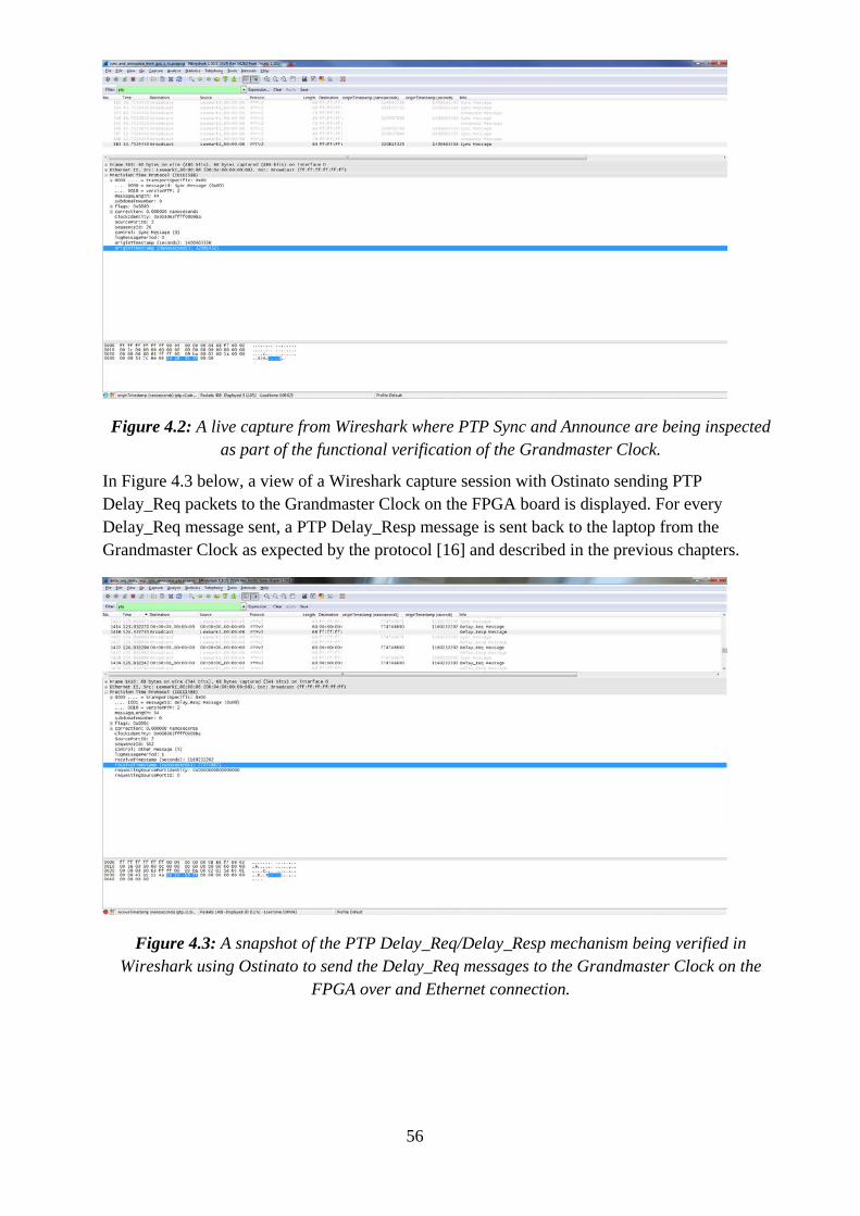
56
Figure 4.2: A live capture from Wireshark where PTP Sync and Announce are being inspected as part of the functional verification of the Grandmaster Clock.
In Figure 4.3 below, a view of a Wireshark capture session with Ostinato sending PTP Delay_Req packets to the Grandmaster Clock on the FPGA board is displayed. For every Delay_Req message sent, a PTP Delay_Resp message is sent back to the laptop from the Grandmaster Clock as expected by the protocol [16] and described in the previous chapters.
Figure 4.3: A snapshot of the PTP Delay_Req/Delay_Resp mechanism being verified in Wireshark using Ostinato to send the Delay_Req messages to the Grandmaster Clock on the
FPGA over and Ethernet connection.
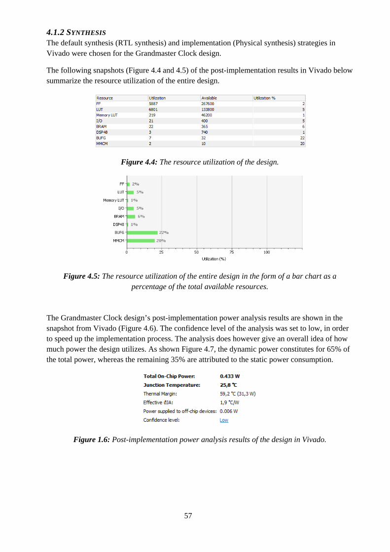
57
4.1.2 SYNTHESIS The default synthesis (RTL synthesis) and implementation (Physical synthesis) strategies in Vivado were chosen for the Grandmaster Clock design.
The following snapshots (Figure 4.4 and 4.5) of the post-implementation results in Vivado below summarize the resource utilization of the entire design.
Figure 4.4: The resource utilization of the design.
Figure 4.5: The resource utilization of the entire design in the form of a bar chart as a percentage of the total available resources.
The Grandmaster Clock design’s post-implementation power analysis results are shown in the snapshot from Vivado (Figure 4.6). The confidence level of the analysis was set to low, in order to speed up the implementation process. The analysis does however give an overall idea of how much power the design utilizes. As shown Figure 4.7, the dynamic power constitutes for 65% of the total power, whereas the remaining 35% are attributed to the static power consumption.
Figure 1.6: Post-implementation power analysis results of the design in Vivado.
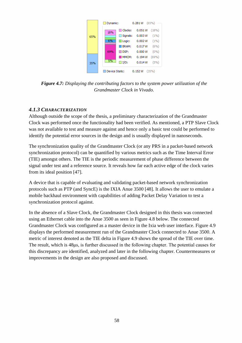
58
Figure 4.7: Displaying the contributing factors to the system power utilization of the Grandmaster Clock in Vivado.
4.1.3 CHARACTERIZATION Although outside the scope of the thesis, a preliminary characterization of the Grandmaster Clock was performed once the functionality had been verified. As mentioned, a PTP Slave Clock was not available to test and measure against and hence only a basic test could be performed to identify the potential error sources in the design and is usually displayed in nanoseconds.
The synchronization quality of the Grandmaster Clock (or any PRS in a packet-based network synchronization protocol) can be quantified by various metrics such as the Time Interval Error (TIE) amongst others. The TIE is the periodic measurement of phase difference between the signal under test and a reference source. It reveals how far each active edge of the clock varies from its ideal position [47].
A device that is capable of evaluating and validating packet-based network synchronization protocols such as PTP (and SyncE) is the IXIA Anue 3500 [48]. It allows the user to emulate a mobile backhaul environment with capabilities of adding Packet Delay Variation to test a synchronization protocol against.
In the absence of a Slave Clock, the Grandmaster Clock designed in this thesis was connected using an Ethernet cable into the Anue 3500 as seen in Figure 4.8 below. The connected Grandmaster Clock was configured as a master device in the Ixia web user interface. Figure 4.9 displays the performed measurement run of the Grandmaster Clock connected to Anue 3500. A metric of interest denoted as the TIE delta in Figure 4.9 shows the spread of the TIE over time. The result, which is 48μs, is further discussed in the following chapter. The potential causes for this discrepancy are identified, analyzed and later in the following chapter. Countermeasures or improvements in the design are also proposed and discussed.
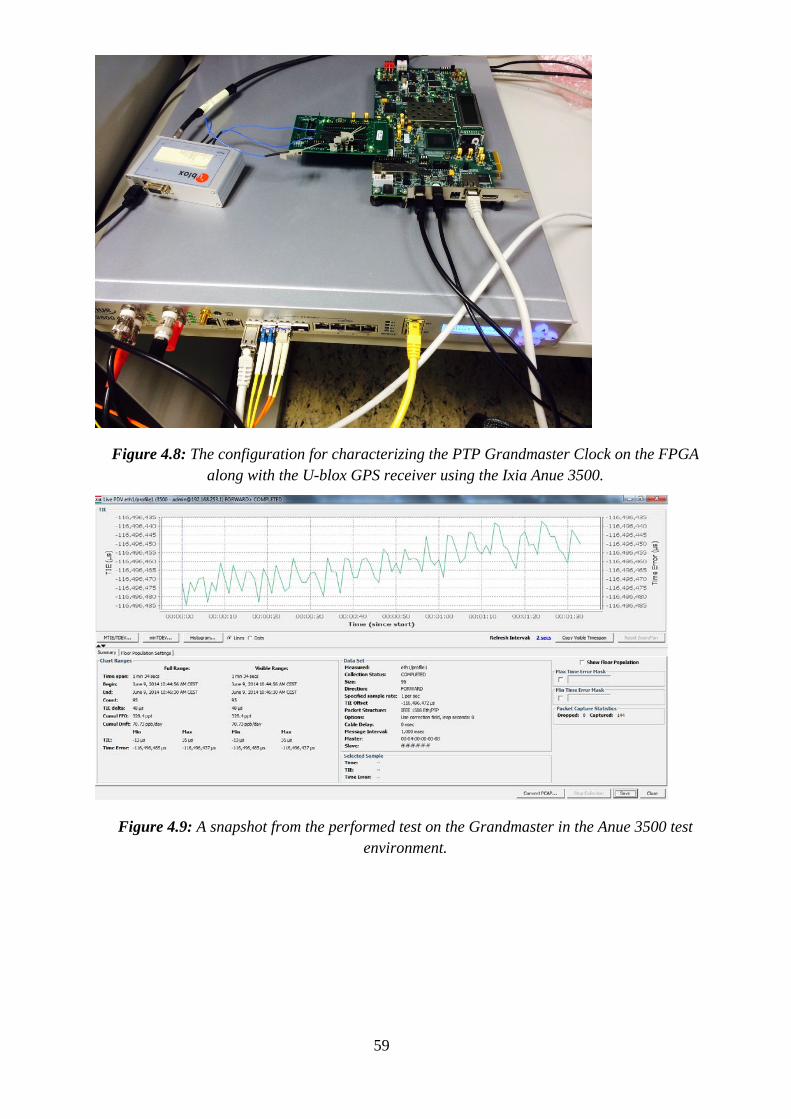
59
Figure 4.8: The configuration for characterizing the PTP Grandmaster Clock on the FPGA along with the U-blox GPS receiver using the Ixia Anue 3500.
Figure 4.9: A snapshot from the performed test on the Grandmaster in the Anue 3500 test environment.
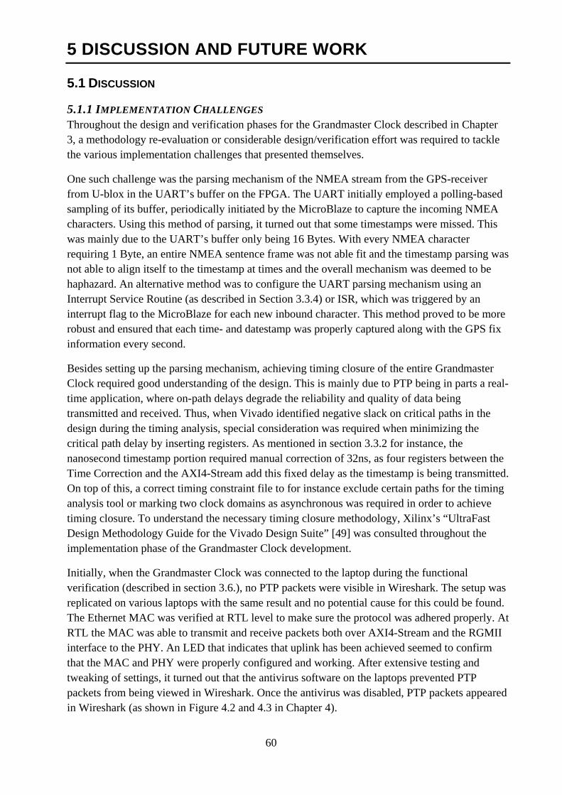
60
5 DISCUSSION AND FUTURE WORK
5.1 DISCUSSION
5.1.1 IMPLEMENTATION CHALLENGES Throughout the design and verification phases for the Grandmaster Clock described in Chapter 3, a methodology re-evaluation or considerable design/verification effort was required to tackle the various implementation challenges that presented themselves.
One such challenge was the parsing mechanism of the NMEA stream from the GPS-receiver from U-blox in the UART’s buffer on the FPGA. The UART initially employed a polling-based sampling of its buffer, periodically initiated by the MicroBlaze to capture the incoming NMEA characters. Using this method of parsing, it turned out that some timestamps were missed. This was mainly due to the UART’s buffer only being 16 Bytes. With every NMEA character requiring 1 Byte, an entire NMEA sentence frame was not able fit and the timestamp parsing was not able to align itself to the timestamp at times and the overall mechanism was deemed to be haphazard. An alternative method was to configure the UART parsing mechanism using an Interrupt Service Routine (as described in Section 3.3.4) or ISR, which was triggered by an interrupt flag to the MicroBlaze for each new inbound character. This method proved to be more robust and ensured that each time- and datestamp was properly captured along with the GPS fix information every second.
Besides setting up the parsing mechanism, achieving timing closure of the entire Grandmaster Clock required good understanding of the design. This is mainly due to PTP being in parts a real-time application, where on-path delays degrade the reliability and quality of data being transmitted and received. Thus, when Vivado identified negative slack on critical paths in the design during the timing analysis, special consideration was required when minimizing the critical path delay by inserting registers. As mentioned in section 3.3.2 for instance, the nanosecond timestamp portion required manual correction of 32ns, as four registers between the Time Correction and the AXI4-Stream add this fixed delay as the timestamp is being transmitted. On top of this, a correct timing constraint file to for instance exclude certain paths for the timing analysis tool or marking two clock domains as asynchronous was required in order to achieve timing closure. To understand the necessary timing closure methodology, Xilinx’s “UltraFast Design Methodology Guide for the Vivado Design Suite” [49] was consulted throughout the implementation phase of the Grandmaster Clock development.
Initially, when the Grandmaster Clock was connected to the laptop during the functional verification (described in section 3.6.), no PTP packets were visible in Wireshark. The setup was replicated on various laptops with the same result and no potential cause for this could be found. The Ethernet MAC was verified at RTL level to make sure the protocol was adhered properly. At RTL the MAC was able to transmit and receive packets both over AXI4-Stream and the RGMII interface to the PHY. An LED that indicates that uplink has been achieved seemed to confirm that the MAC and PHY were properly configured and working. After extensive testing and tweaking of settings, it turned out that the antivirus software on the laptops prevented PTP packets from being viewed in Wireshark. Once the antivirus was disabled, PTP packets appeared in Wireshark (as shown in Figure 4.2 and 4.3 in Chapter 4).
61
5.1.2 SOURCES OF ERROR There are several factors that can affect the synchronization quality of IEEE 1588 PTP over Ethernet. Some potential error sources have been identified in the PTP Grandmaster Clock design, which may provide some explanation to why the TIE delta (in section 4.1.3.) was so high. As mentioned in section 2.2.2, the timestamp insertion point in the Grandmaster Clock greatly determines the achievable level of synchronization accuracy. The Grandmaster Clock implementation in this thesis inserts the timestamp before the MAC layer, and thus is not able to account for the delay at the MAC and PHY layers, before a PTP packet is transmitted over Ethernet. The components of this on-path delay are identified in this section. On top of this, the choice of crystal oscillator, greatly determines the short-term jitter that is currently not taken care of by the current implementation.
The Ethernet MAC consists of a fixed and a variable delay, of which the fixed one can be compensated for as in the case of the Packet Generator previously mentioned. The variable delay is due to the Ethernet protocols non-deterministic collision detection back-off mechanism, and cannot be compensated for statically. This collision detection and non-deterministic back-off mechanism hinders the precise time of packet transmission from being known until the packet is completely sent without a collision being detected. At this point in the packet’s transmission, it is impossible to alter the its content in the current implementation. A method to overcome this is to amend the timestamp as close to the PHY as possible through hardware timestamping. Thus a run-time on-path residence-time calculation and compensation mechanism could be employed to tackle this delay. This requires tapping into or intercepting the MII interface in order to access the PTP packet as it is on its way. A solution that incorporates this mechanism is further discussed in the following section.
Further, the PHY layer itself comes with a level of uncertainty and non-determinism that degrades the quality of the timestamp in the PTP messages. The PHY may have asymmetric path delay in the Tx and Rx directions, which if not taken into account in the timestamp add another level of degradation of timestamp quality. In order to mitigate this, a PTP-friendly PHY may be chosen that addresses the path asymmetry to improve the quality of the PTP application using it.
As mentioned, the choice of the local reference clock’s oscillator may impact the rate of drift between Grandmaster and Slave Clocks. The better the quality of the crystal oscillator used in the Grandmaster Clock, the more the accurate the Slave Clock remains in between the PTP Sync message updates [50]. The implementation in this thesis uses a lower grade crystal (XO) oscillator with a 50PPM (Parts Per Million) error. Physical factors such as temperature, crystal’s aging profile and vibrations are some contributing error sources that cause jitter in the oscillator. Using a higher quality oscillator could greatly improve the results shown in section 4.1.3.
According to the IEEE 1588-2008 standard, the Grandmaster Clock may support a holdover mode when it loses its PRS (in this case a GPS-fix). The holdover mode requires the capability to still act as a Grandmaster with degraded synchronization reliability. This loss in reliability is thus reflected in the contents of the Announce packets, where the clock stratum number is demoted to a lower level and the BMCA will try to elect a new Grandmaster capable device in the PTP domain. This is a feature that needs to be added to the current implementation. Currently, the Grandmaster Clock immediately stops sending Sync messages as well stops responding to incoming Delay_Req messages.
62
5.2 FUTURE WORK The current implementation inserts the timestamp before the MAC layer (as described in section 2.2.2.), via the AXI4-Stream interface and does not account for the variable and non-deterministic delay at the MAC and PHY layers mentioned in the previous section. A method that could be employed in order to improve the synchronization quality is to use a Time Stamp Unit (TSU) that taps into the MII interface between the MAC and PHY layers. This method is also used by for instance Sven Meier, Hans Weibel and Karl Weber in their implementation of the PTP (as discussed in section 2.6). The TSU enables a hardware-timestamp mechanism in order to mitigate the loss in precision due to the non-deterministic MAC layer by compensating a timestamp on-the-fly with the on-path delay the PTP packets spend inside the MAC. This is done by timestamping the ingress and egress points in time and adding their difference to the timestamp field of the PTP packet being transmitted/received. An IP from Xilinx that supports such a feature is the AXI Ethernet MAC over 10 Gigabit [51]. It can be configured to either work as a one-step or two-step clock (see section 2.2.) and can either add the correction to the timestamp in a Time of Day (ToD) format or add a 64bit correction in a separate field in the nanosecond precision.
The current PHY could eventually be replaced with an on-board Small Form-factor Pluggable (SFP) transceiver cage, in order to allow the PTP protocol to operate over an optical network via a fiber connection. This should also improve the asymmetric delay in the current PHY to a certain extent. Using an IEEE-1588 compliant PHY that can compensate the transit latency and add it to the PTP packets on the fly in a correction field, is yet another feature that needs to be explored.
The current crystal oscillator could be replaced by for instance a higher quality Temperature-Controlled Crystal Oscillator (TCXO), Voltage-Controlled Crystal Oscillator (VCXO) or an Oven-Controlled Crystal Oscillator (OCXO) to provide higher stability in the Grandmaster’s local clock. This comes at a price in terms of an increase in area, power and places additional constraints on heat dissipation of the packaging or casing. Thus, the choice is heavily dependent on the constraints and specifications of the application where and how the Grandmaster will be used.
As the coordinates for the GPS-receiver can also be parsed from the inbound NMEA stream, information regarding the location could also be extracted if so desired by the user. However, this could also be sensitive information and could thus pose a security risk and should in that case be omitted (as in the current implementation).
The current version of the PTP Grandmaster Clock is targeted to handle one Slave Clock with which it exchanges Delay_Req and Delay_Resp type messages. The Grandmaster IP’s Packet Generator should eventually be extended to be able to service multiple Delay_Req messages using a message FIFO to buffer and handle the requests in a first-come-first-serve basis, as specified in the IEEE-1588-2008 standard [16].
The Packet Generator is also currently hard-coded to send Sync and Announce packets at a fixed rate and cannot be re-configured externally. An I2C bus that can access registers inside the Grandmaster IP that are dedicated to set the transmission rate of PTP packets should be added to the current implementation.
63
5.3 CONCLUSION An IEEE 1588-2008 PTP Grandmaster Clock using a GPS-receiver has been successfully implemented on an FPGA in this thesis. The Grandmaster is able to send and receive PTP packets over Ethernet, which has been verified using Wireshark and Ostinato. The results of the functional verification as well as the development and testing phases have been documented.
In order to ensure that the Grandmaster Clock is compliant with the upcoming Satellite Navigation standards besides GPS, a GLONASS/BEIDOU compatible receiver was chosen as the PRS. This is thought to both add redundancy of a single Satellite Navigation system as well as reduce the potential politically motivated dependencies of the government-owned (American) GPS-system.
Although outside the initial scope of the thesis, a basic characterization has also been performed in order to identify the weaknesses and potential points of improvement with the design. The results of this characterization have been analyzed and solutions that could mitigate the loss in synchronization quality have been proposed.
In order to achieve the desired accuracy of the IEEE 1588 standard, the potential improvements that have been identified and documented, should be added to the current implementation. Once this has been achieved, the Grandmaster Clock is thought to have the necessary functional blocks as well as architecture to fulfill the network synchronization requirements of most applications.
64
6 REFERENCES
[1] Lewis Jeremy. (2013, April) Precise Timing over Ethernet Networks. [Online]. http://www.ethernetsummit.com/English/Collaterals/Proceedings/2013/20130403_B101_Lewis.pdf
[2] Cisco. (2014) Cisco US. [Online]. http://www.cisco.com/c/en/us/solutions/collateral/service-provider/visual-networking-index-vni/white_paper_c11-520862.pdf
[3] M Vinod Kumar Dr. Sarath Kumar. Synchronization in Packet Switched Networks - A Survey of Existing Techniques. [Online]. http://www.tejasnetworks.com/images/White%20Paper/Synchronization%20In%20Packet%20Switched%20Networks.pdf
[4] Dirk Mohl Andreas Dreher. (2009, July) White Paper, Precision Clock Synchronization, The Standard IEEE 1588. [Online]. http://www.belden.com/pdfs/Techpprs/Precision_Clock_Synchronization_WP.pdf
[5] Prof. Hans Weibel. (2005, July) IEEE 1588, Standard for a Precision Clock Synchronization Protocol. [Online]. http://www.ines.zhaw.ch/fileadmin/user_upload/engineering/_Institute_und_Zentren/INES/IEEE1588/Dokumente/IEEE_1588_Tutorial_engl_250705.pdf
[6] Kishan Shenoi. (2013, April) Clocks, Oscillators, and PLLs. [Online]. http://tf.nist.gov/seminars/WSTS/PDFs/1-1_Qulsar_Shenoi_tutorial.pdf
[8] Peter Gaspar. (2010) Frequency and Time Synchronization In - Packet Based Networks. [Online]. https://www.cisco.com/web/YU/expo2010/pdfs/Prenos_frekvencije_i_faza_preko_paketskih_mreza.pdf
[7] Kang Lee. (2009, August) Introduction to IEEE 1588. [Online]. http://www.nist.gov/el/isd/ieee/intro1588.cfm
[9] National Instruments. (2013, October) Introduction to Distributed Clock Synchronization and the IEEE 1588 Precision Time Protocol. [Online]. http://www.ni.com/white-paper/2822/en/#toc1
[10] Hans Weibel. (2012) Zurich University of Applied Sciences. [Online]. http://www.in2p3.fr/actions/formation/Numerique12/IEEE_1588_Tutorial_IN2P3_Handout.pdf
[11] Belden. (2014) Precision Time Protocol. [Online]. http://www.hirschmann.com/en/Hirschmann_Produkte/Industrial_Ethernet/Technologies/Precision_Time_Protocol/index.phtml
[12] John Eidson. (2005, May) IEEE-1588 Standard for a Precision Clock Synchronization Protocol for Networked Measurement and Control Systems. A Tutorial. [Online]. http://www.nist.gov/el/isd/ieee/upload/tutorial-basic.pdf
[13] Caleb Gordon. (2009) White Paper Introduction to IEEE 1588 & Transparent Clocks. [Online]. http://tekron.com/sites/default/files/transparent_clock_whitepaper.pdf
65
[14] John Eidson. (2005, Oct) IEEE-1588 Standard for a Precision Clock Synchronization Protocol for Networked Measurement and Control Systems. [Online]. http://www.nist.gov/el/isd/ieee/upload/tutorial-basic.pdf
[15] Jean-Loup Ferrant, Syncronous Ethernet and IEEE 1588 in Telecom, 1st ed. Croyton, UK: Wiley, 2013.
[16] (2008, July) IEEE Standard for a Precision Clock Synchronization Protocol for Networked Measurement and Control Systems," IEEE Std 1588-2008 (Revision of IEEE Std 1588-2002). [Online]. http://ieeexplore.ieee.org/stamp/stamp.jsp?tp=&arnumber=4579760&isnumber=4579759
[18] Mike Johnson. (2012, March) IEEE1588v2 Transparent Clock Benefits for Industrial Control Distributed Networks. [Online]. http://www.micrel.com/_Products/LanSolutions/GetInSync.pdf
[17] EndRun Technologies. (2014, June) IEEE-1588 precision time protocol synchronisation. [Online]. http://www.iebmedia.com/index.php?id=9752&parentid=74&themeid=255&hft=78&showdetail=true&bb=1
[19] Dominic Béchaz Hans Weibel. (2004, September) IEEE 1588 Implementation and Performance of Time Stamping Techniques. [Online]. https://home.zhaw.ch/~wei/IEEE1588/PTP_Timestamping_Methods_Paper.pdf
[20] Dr. Douglas Arnold. (2013, September) Why is IEEE 1588 so accurate? [Online]. http://blog.meinbergglobal.com/2013/09/14/ieee-1588-accurate/
[21] (2010) Implementation of PTP. [Online]. http://www.ieee1588.com/IEEE1588_Implementation_of_PTP.html
[22] Patrick Donegan. (2011, June) Heavy Reading. [Online]. www.heavyreading.com
[23] Valentin Cristea, Logica Banica Teodor Neagoe, "NTP versus PTP in Computer Networks Clock Synchronization," Industrial Electronics, 2006 IEEE International Symposium on1, vol. 1, p. 1, July 2006.
[24] (2008, December) Network Time Protocol: Best Practices White Paper. [Online]. http://www.cisco.com/c/en/us/support/docs/availability/high-availability/19643-ntpm.html#overview
[25] Jaques Azoubib, and William J. Klepczynski Wlodmierz Lewanddowski, "GPS: Primary Tool for Time Transfer," Proceedings of the IEEE, vol. 87, no. 1, p. 1, January 1999.
[26] Spectracon. (2014) GPS Clock Synchronization. [Online]. http://www.spectracomcorp.com/ProductsServices/ByApplication/GPSClockSynchronization/tabid/100/Default.aspx
[28] James Aweya, "Emerging Applications of Synchronous Ethernet in Telecommunication Networks," Circuits and Systems Magazine, vol. 12, no. 2, p. 59, May 2012.
[27] Zhijun Deng, "Time Synchronization Using Single GPS-Satellite and Multiple Measurement Stations," in Internet Computing for Science and Engineering (ICICSE), 2012 Sixth International Conference,
66
Henan, 2012, p. 228.
[29] ALBEDO Telecom. (2012) Synchronous Ethernet explained. [Online]. http://www.albedotelecom.com/src/lib/WP-SynE-explained.pdf
[30] Huawei. (2012, October) Synchronous Ethernet and IEEE 1588v2 Technology White Paper. [Online]. http://enterprise.huawei.com/ilink/enenterprise/download/HW_194944
[31] John C. Eidson, Measurement, Control and Communication Using IEEE 1588, Illustrated ed. London, UK: Springer, 2006, ISBN 1-84628-250-0.
[32] Steve Kostecke. (2003, July) Understanding and using the Network Time Protocol. [Online]. http://www.ntp.org/ntpfaq/NTP-s-algo.htm#Q-ALGO-BASIC-STRATUM
[33] Ublox. (2014) Ublox Technology. [Online]. http://www.u-blox.com/en/timing.html
[34] Peter Bennet. (1997, September) The NMEA FAQ. [Online]. http://www.kh-gps.de/nmea.faq
[35] Hans Weibel, Karl Weber Sven Meier, "IEEE 1588 Syntonization and Synchronization Functions Completely Realized in Hardware," in ISPCS 2008 – International IEEE Symposium on Precision Clock Synchronization for Measurement, Control and Communication, Michigan, September 2008, pp. 1-4.
[36] Neagoe Teodor, Hamdi Maher, and Cristea Valentin, "Frequency Compensated, Hardware IEEE-1588 Implementation," in International Symposium on Industrial Electronics, Montreal, 2006, pp. 240 - 245.
[38] Xilinx. (2014, May) Vivado Design Suite User Guide. [Online]. http://www.xilinx.com/support/documentation/sw_manuals/xilinx2014_1/ug896-vivado-ip.pdf
[37] Xilinx. (2014, February) 7 Series FPGAs Overview. [Online]. http://www.xilinx.com/support/documentation/data_sheets/ds180_7Series_Overview.pdf
[39] Xilinx. (2013, January) AC701 Evaluation Board Features. [Online]. http://www.ti.com/lit/ug/tidu150/tidu150.pdf
[40] Xilinx. (2013) AXI4-Stream Interconnect. [Online]. http://www.xilinx.com/ipcenter/axi4.htm
[41] Xilinx. (2012, January) LogiCORE IP AXI4-Lite IPIF (v1.01.a). [Online]. http://www.xilinx.com/support/documentation/ip_documentation/axi_lite_ipif_ds765.pdf
[42] Xilinx. (2014, April) LogiCORE IP AXI Interconnect v2.1. [Online]. http://www.xilinx.com/support/documentation/ip_documentation/axi_interconnect/v2_1/pg059-axi-interconnect.pdf
[43] (2014, April ) LogiCORE IP AXI UART Lite v2.0 Product Guide. [Online]. http://www.xilinx.com/support/documentation/ip_documentation/axi_uartlite/v2_0/pg142-axi-uartlite.pdf
67
[44] IEEE. (2012) IEEE 802.3 Ethernet - IEEE Standard for Internet. [Online]. http://standards.ieee.org/about/get/802/802.3.html
[45] Xilinx. (2014, April) LogiCORE IP Tri-Mode Ethernet MAC v8.2 Product Guide. [Online]. http://www.xilinx.com/support/documentation/ip_documentation/tri_mode_ethernet_mac/v8_2/pg051-tri-mode-eth-mac.pdf
[46] Xilinx. (2013) Xilinx Plug-and-Play IP: Accelerating Productivity and Design Reuse. [Online]. http://www.xilinx.com/publications/prod_mktg/ipcenter/Plug_and_Play_IP_backgrounder.pdf
[48] Ixia. (2014) Ixia Anue 3500: Overview. [Online]. http://www.ixiacom.com/products/network_test/load_modules/anue_3500/
[47] Tektronix. (2014) Understanding and Characterizing Timing Jitter Primer. [Online]. http://info.tek.com/Understanding-and-Characterizing-Timing-Jitter-Primer-LP.html
[49] Xilinx. (2014, April) UltraFast Design Methodology Guide for the Vivado Design Suite. [Online]. http://www.xilinx.com/support/documentation/sw_manuals/ug949-vivado-design-methodology.pdf
[50] M. Felser, "Real-Time Ethernet - Industry Prospective," in Proceedings of the IEEE, vol. 93, Burgdorf, 2005, pp. 1118 - 1129.
[51] Xilinx. (2014, April) LogiCORE IP AXI 10-Gigabit Ethernet v1.2. [Online]. http://www.xilinx.com/support/documentation/ip_documentation/axi_10g_ethernet/v1_2/pg157-axi-10g-ethernet.pdf
[52] David L. Mills, "Internet Time Synchronization: The Network Time Protocol," IEEE TRANSACTIONS ON COMMUNICATIONS, vol. 39, no. 10, p. 1, October 1991.
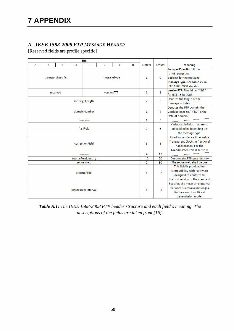
68
7 APPENDIX
A - IEEE 1588-2008 PTP MESSAGE HEADER [Reserved fields are profile specific]
Table A.1: The IEEE 1588-2008 PTP header structure and each field’s meaning. The descriptions of the fields are taken from [16].
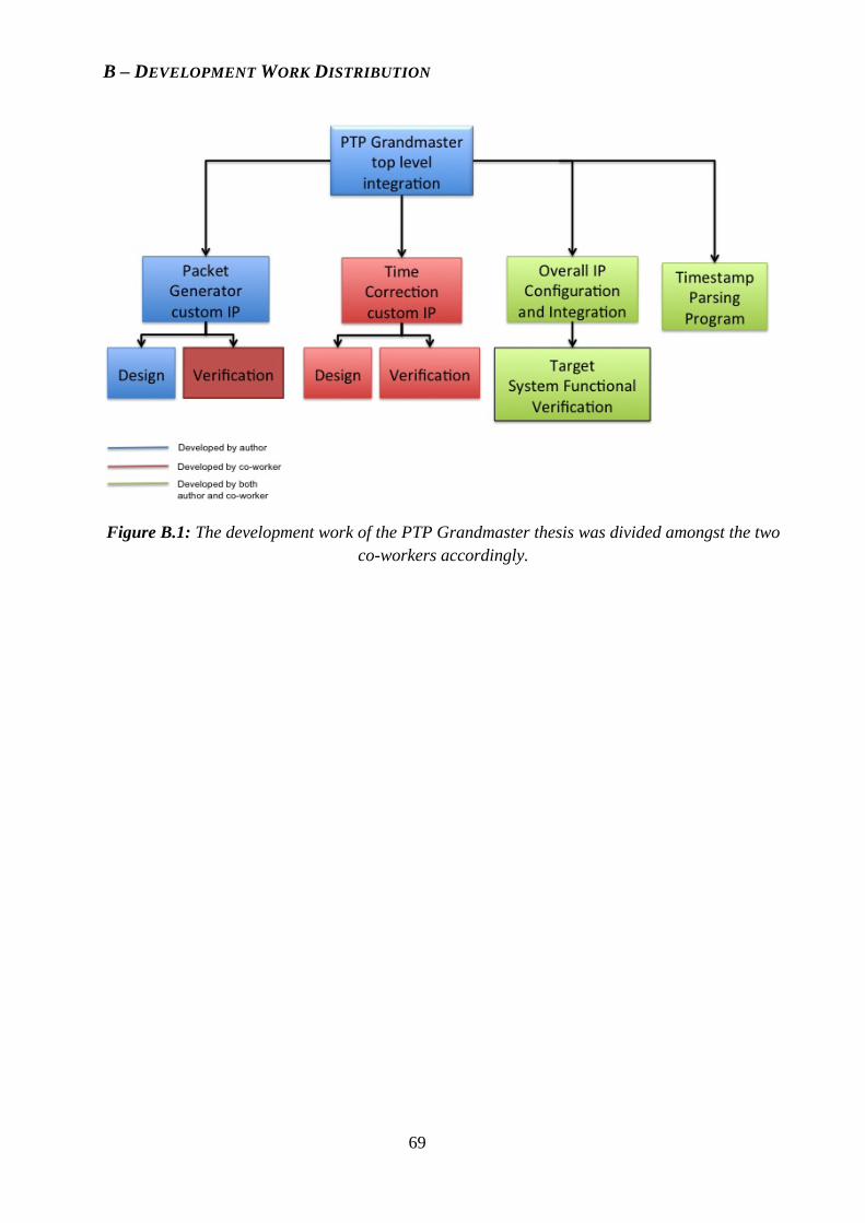
69
B – DEVELOPMENT WORK DISTRIBUTION
Figure B.1: The development work of the PTP Grandmaster thesis was divided amongst the two co-workers accordingly.