quadrant fabrication study
DESCRIPTION
Quadrant Fabrication Study. KEK Toshikazu TAKATOMI Yuichi WATANABE. 2nd Collaboration Meeting on X-band Accelerator Structure Design and Test-Program 13-15 May 2008. Test Quadrant Structure. This structure is made for four parts. - PowerPoint PPT PresentationTRANSCRIPT
Quadrant Fabrication Study
KEK
Toshikazu TAKATOMI
Yuichi WATANABE
2nd Collaboration Meeting on X-band Accelerator Structure Design and Test-Program13-15 May 2008
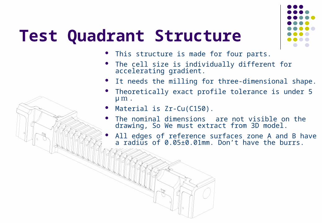
Test Quadrant Structure This structure is made for four parts. The cell size is individually different for accelerating gradient. It needs the milling for three-dimensional shape. Theoretically exact profile tolerance is under 5 μ m . Material is Zr-Cu(C150). The nominal dimensions are not visible on the drawing, So
We must extract from 3D model. All edges of reference surfaces zone A and B have a radius
of 0.05±0.01mm. Don’t have the burrs.
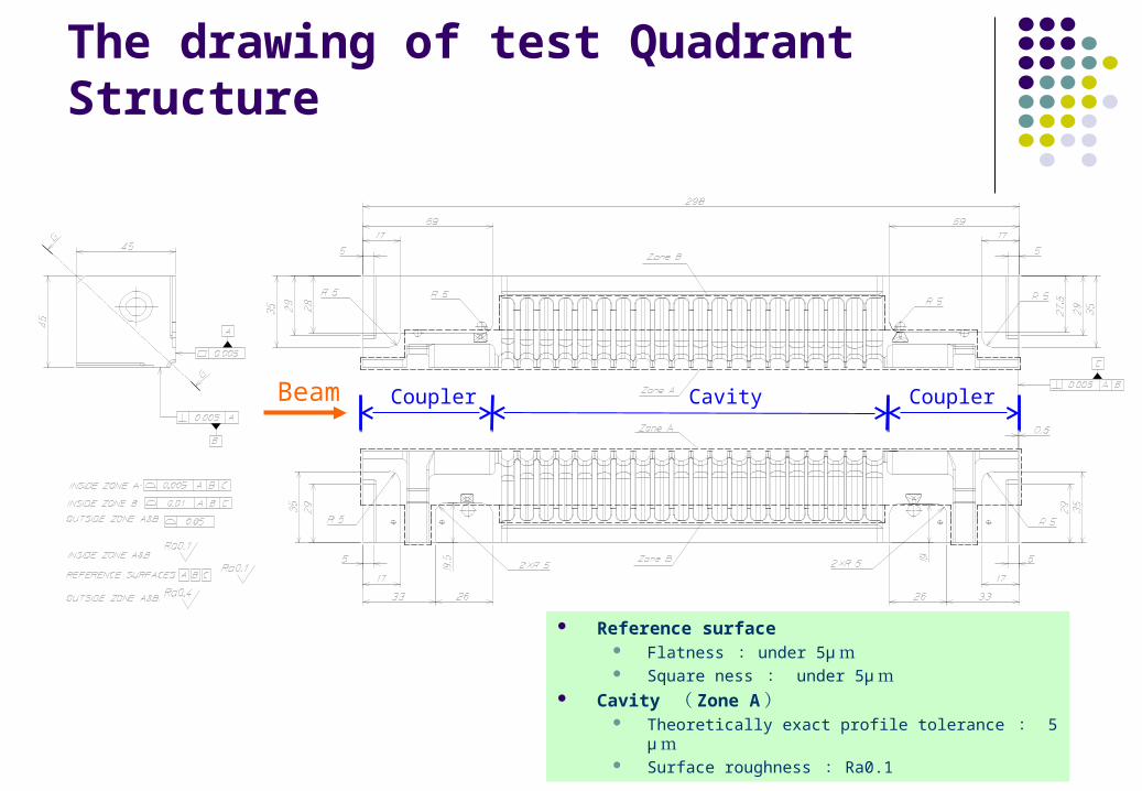
The drawing of test Quadrant Structure
Reference surface Flatness : under 5μ m Square ness : under 5μ m
Cavity ( Zone A ) Theoretically exact profile tolerance : 5 μ m Surface roughness : Ra0.1
Beam Coupler Cavity Coupler
Issues in processing
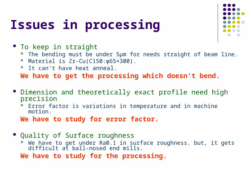
To keep in straight The bending must be under 5μm for needs straight of beam line. Material is Zr-Cu(C150:φ65×300). It can't have heat anneal.We have to get the processing which doesn't bend.
Dimension and theoretically exact profile need high precision Error factor is variations in temperature and in machine motion.
We have to study for error factor.
Quality of Surface roughness We have to get under Ra0.1 in surface roughness. but, it gets difficult at
ball-nosed end mills.
We have to study for the processing.
Points of Fabrication
Fabrication was the 5-axis precision machine that is controlled with constant temperature at 23±0.5 ℃degrees.
CAM data was made to change in 23 degrees ℃temperature.
We studied to find the best processing.
Alignment of the machine and shape of the tools was measured to keep high precision.
It is processed four times to repair bend.

Flatness measurement of referencesReference surface A
-0.010
-0.005
0.000
0.005
0.010
1 3 5 7 9 11 13 15 17 19 21 23 25 27 29 31
point No.
diffe
renc
e(μm
)
ABCD
Reference A
Measurement point
Reference surface got at under 6 μ m .(under 4 μ m at cavity)Reference B
Reference surface B
-0.010
-0.005
0.000
0.005
0.010
1 3 5 7 9 11 13 15 17 19 21 23 25 27 29 31
point No.
diff
ere
nce
(μm
)ABCD
D C B A A B C D
123
4
5
6n
Non fixation
Non fixation
Cavity
Cavity
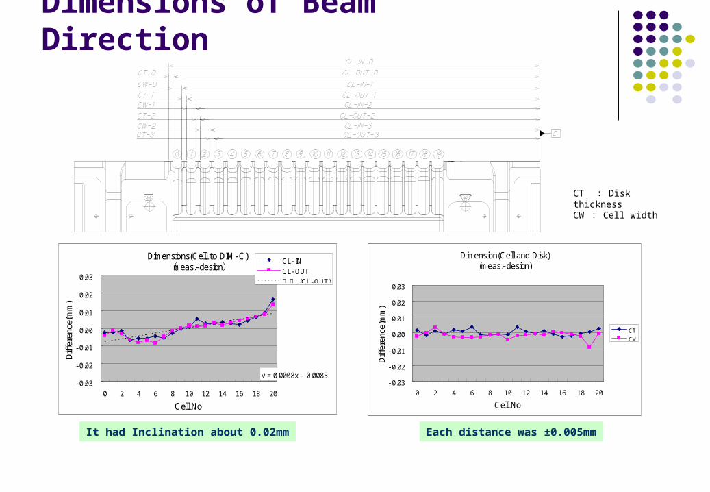
Dimensions of Beam Direction
It had Inclination about 0.02mm Each distance was ±0.005mm
CT : Disk thicknessCW : Cell width
Dimensions(Cell to DIM-C)meas.- design( )
y = 0.0008x - 0.0085- 0.03
- 0.02
- 0.01
0.00
0.01
0.02
0.03
0 2 4 6 8 10 12 14 16 18 20
Cell No.
Difference(mm)
CL- INCL- OUT
(CL- OUT)線形
Dimension(Cell and Disk)(meas.- design)
- 0.03
- 0.02
- 0.01
0.00
0.01
0.02
0.03
0 2 4 6 8 10 12 14 16 18 20
Cell No.
Difference(mm)
CT
CW
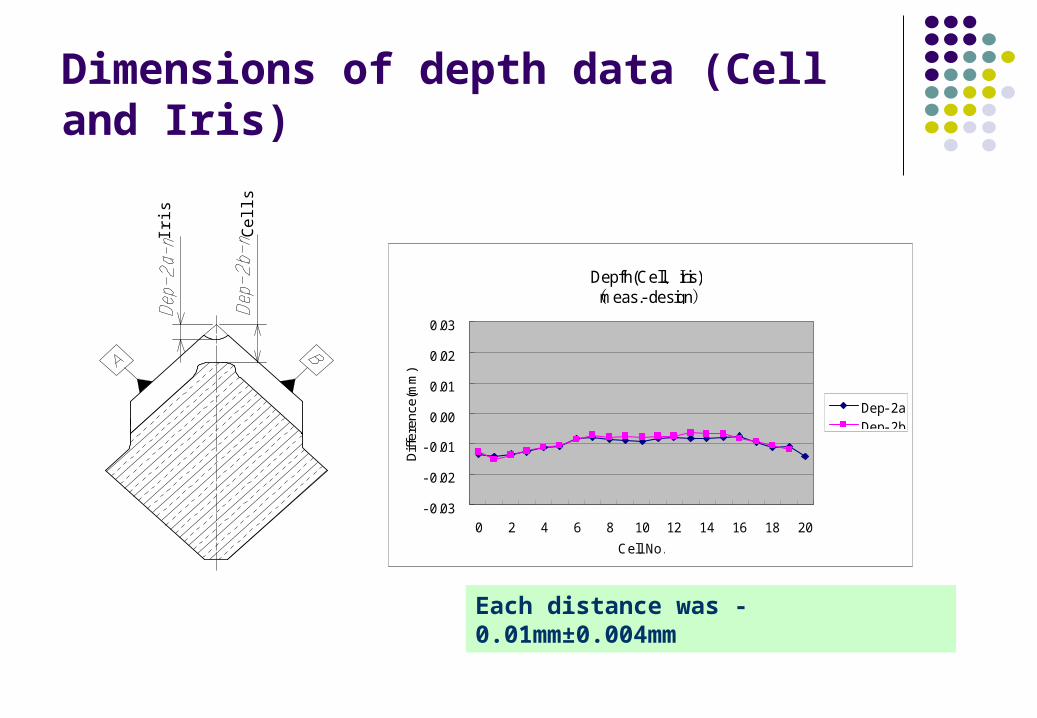
Dimensions of depth data (Cell and Iris)
Each distance was -0.01mm±0.004mm
Depfh(Cell ris)、Imeas.- design( )
- 0.03
- 0.02
- 0.01
0.00
0.01
0.02
0.03
0 2 4 6 8 10 12 14 16 18 20
Cell No.
Difference(mm)
Dep- 2aDep- 2b
Iris
Ce
lls
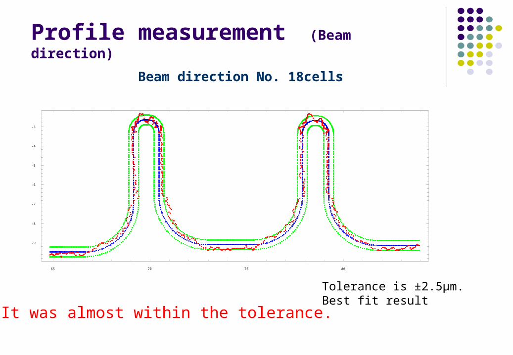
Profile measurement (Beam direction)
65 70 75 80
-9
-8
-7
-6
-5
-4
-3
Beam direction No. 18cells
Tolerance is ±2.5μm.Best fit result
It was almost within the tolerance.

Profile measurement (cross direction)
-15 -10 -5 0 5 10 15
-18
-16
-14
-12
-10
Cross direction of No.18cell
Cross direction of No.18iris
-10 0 10 20
-20
-15
-10
-5
0
It’s OK!
It had error about 5μm.
Tolerance is ±2.5μm.Best fit result
Tolerance is ±2.5μm.Best fit result
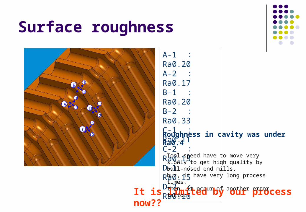
Surface roughness
Roughness in cavity was under Ra0.4
A-1 : Ra0.20A-2 : Ra0.17B-1 : Ra0.20B-2 : Ra0.33C-1 : Ra0.11C-2 : Ra0.13D-1 : Ra0.15D-2 : Ra0.16
1
2
1
2
1
2
1
2
A
B
C
D
It is limited by our process now??
Tool speed have to move very slowly to get high quality by ball-nosed end mills.but, it have very long process times. then ,it occur of another error factor.

Inspection of edgesSide A
input output
Iris_0-1_sideA Iris_11-12_sideA Iris_18-19_sideAIris_5-6_sideA
Burr was not seen.It had edges of chamfering at 0.05mm. This is good!
Summary Reference surface got at under 6 μ m . Cavity was under 4 μ m . Dimensions of beam direction had inclination about 0.02mm. It
was gotten variations in temperature.
We had to study. Profile measurement at beam direction was almost in the
tolerance. Roughness in cavity was under Ra0.4
In the future, we will reach the goal based on those results.
AcknowledgmentWe would like to express my gratitude to U-CORPORATION Co.,Ltd and Hitachi,Ltd about fabrication study.