repair method using cfrp sheet for corroded gusset plate …
TRANSCRIPT
REPAIR METHOD USING CFRP SHEET
FOR CORRODED GUSSET PLATE CONNECTION IN TRUSS BRIDGES
Ngoc Vinh PHAM1, Takeshi MIYASHITA2, Kazuo OHGAKI3, Yusuke OKUYAMA4, Akira KOBAYASHI5, Yuya HIDEKUMA6, Takeshi HIROSE7 and Takuya HARADA8
1Member of JSCE, Ph.D. Candidate, Nagaoka University of Technology
(1603-1, Kamitomioka Nagaoka, Niigata 940-2188, Japan) E-mail: [email protected]
2Member of JSCE, Associate Professor, Nagaoka University of Technology (1603-1, Kamitomioka Nagaoka, Niigata 940-2188, Japan)
E-mail: [email protected] 3Member of JSCE, Professor, Institute of Technologists (333 Maeya, Gyoda, Saitama 361-0038, Japan)
E-mail: [email protected] 4Member of JSCE, Assistant Professor, National Institute of Technology, Nagano College
(716 Tokuma, Nagano 381-8550, Japan) E-mail: [email protected]
5Member of JSCE, General Manager, Nippon Steel & Sumikin Material Co. (7-16-13, Ginza, Chuo-ku, Tokyo 104-0061, Japan)
E-mail: [email protected] 6Member of JSCE, Chief, Nippon Steel & Sumikin Material Co. (7-16-13, Ginza, Chuo-ku, Tokyo 104-0061, Japan)
E-mail: [email protected] 7Member of JSCE, General Manager, Nippon Expressway Research Institute Co.
(1-4-1 Tadao, Machida, Tokyo 194-8508, Japan) E-mail: [email protected]
8Member of JSCE, Nippon Expressway Research Institute Co. (1-4-1 Tadao, Machida, Tokyo 194-8508, Japan) E-mail: [email protected]
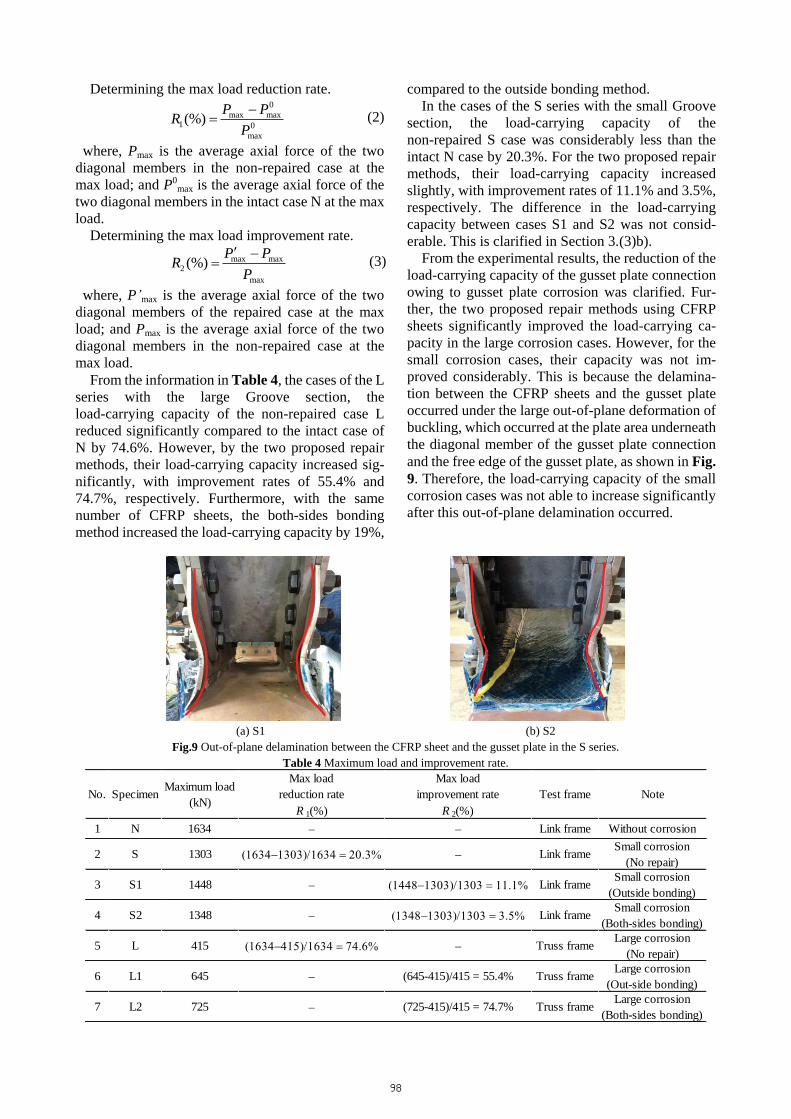
Recently, damage to steel truss bridges due to corrosion has become a serious problem worldwide. In particular, severe damage due to corrosion at gusset plate connection is being widely reported. Corroded gusset plates that have reduced load-carrying capacity can lead to the collapse of the entire bridge. At-tachment of stiffening plate and member replacement are among the conventional methods often applied to repair corroded structures. However, these repair works lack efficacy because of the heavy machinery and welding facilities required. In this study, two carbon fiber-reinforced polymers (CFRP) bonding methods, outside bonding and both-sides bonding, are proposed to improve the strength of the corroded gusset plate connection and decrease stress on the corroded section of the gusset plate. CFRP is used as the repair material for the corroded gusset plate connection in the proposed methods because of its light weight, high strength, and superior durability. Loading tests were conducted with a model approximately 50% the size of a real bridge and degrees of corrosion assumed to be approximately 50% and 75% of the gusset plate thickness. Key Words : corrosion, truss bridge, corroded gusset plate connection, repair method, CFRP
1. INTRODUCTION
In steel truss bridges, severe damage due to the corrosion at the gusset plate connection has been reported. The reduction of the load-carrying capacity of the corroded gusset plate connection has been confirmed to lead to the collapse of the entire truss bridge. The collapse of the I-35W steel truss bridge (in the USA, 2007)1)-5) because of insufficient gusset
plate thickness, which resulted in the connection having a lower load-carrying capacity, is considered a typical case. In the case of the Choshi bridge in Japan, the corrosion damage severely affected such members of this bridge as the diagonal members, lower chords, and gusset plate connections. Because of the high level of the damage, this bridge was dismantled completely in 2009 after nearly 50 years of service6)-8). Moreover, numerous studies have
Journal of JSCE, Vol. 6, 91-109, 2018
91
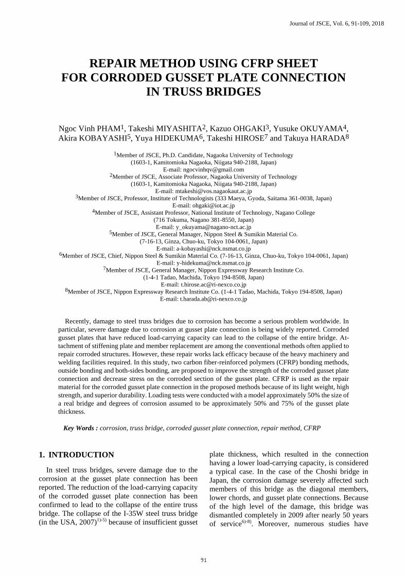
shown that corrosion frequently occur on the gusset plate connection members because of their complex shapes and debris and water accumulation. These locations are shown in Fig. 1. However, repair methods that use high-tension bolts or welding for these corroded locations are very difficult, and new construction or replacement for these corroded members is very expensive. Thus, finding a simpler and more cost-effective repair method is highly de-sired by bridge engineers.
The traditional methods often used to repair cor-roded structures include attaching stiffening plates onto corroded members using bolts or welding, and replacing an old member with a new member9). However, these repair methods lack efficacy because heavy machinery, welding works, and the presence of professional engineers to perform quality control are required, which significantly increase the repair cost. In addition, these methods induce some amount of deterioration of corroded members, such as loss of cross-section owing to the use of bolts and the in-fluence of heat stress owing to welding.
The applicability of carbon fiber-reinforced pol-ymers (CFRP) as materials for repairing and strengthening aging or damaged structures is being intensively investigated worldwide, such as in the USA from the 1970s10), and Japan and China from the 1980s11). CFRP in sheet form is usually applied to repair and strengthen steel structures that have re-duced load-carrying capacity due to natural hazards,
human errors, accidents, corrosion damages, and fatigue damage. Moreover, CFRP sheet is also used to improve structures with reduced load-carrying capacity due to change in the purpose of the structure utility. However, application to steel structures for corrosion and fatigue factors is the most common. Numerous studies have already verified the effec-tiveness of using the CFRP sheets to reinforce the corroded members; specifically, the members sub-jected to axial stress such as the chord members of the truss bridge and the lower flange of I-girder steel bridges12)-14), and the members subjected to reaction force (compressive stress) such as the vertical stiff-ener at the supports of I-girder steel bridges12),15)-17). In addition, recovering from the shear buckling strength of the corroded web in steel girder bridges by using the CFRP sheets was also investigat-ed12),18),19). However, to the best of our knowledge, to date there are no cases in which CFRP sheets have been applied for the corroded gusset plate connec-tions.
Therefore, in order to establish a proper repair method for the corroded gusset plate connection, this study proposes two CFRP-sheet-based repair meth-ods after investigating the effectiveness of using CFRP sheets as a repair material for the corroded gusset plate connections. The improvement rate of the strength of the corroded gusset plate was evalu-ated through loading tests using actual laboratory models.
Fig.1 Frequently corroded locations on steel truss bridges.
4000
Loading Device
2000
1500
12001400 1400
Truss Frame System
SpecimenGroove
U
D4 D3 D2 D1
L1L2
8
20 202006
6
199
8200
4
SS400
Groove
1200
295
600
4
4Zh
8
Zt
56
The detail of Groove section
bolt
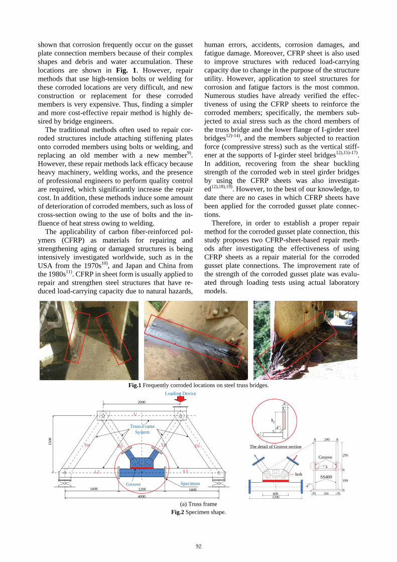
(a) Truss frame
Fig.2 Specimen shape.
92
1200
1180
1520
500
610
Loading Device
Specimen
L1
L2
L3
D1
D2
Link Frame System
Groove
2000
8
20 202006
6
199
8200
4
SS400
Groove
1200
295
600
4
4Zh
8
Zt
56
The detail of Groove section
bolt
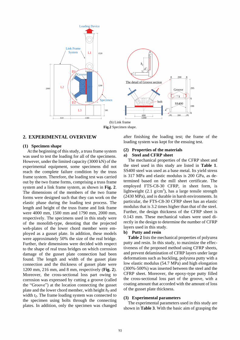
(b) Link frame
Fig.2 Specimen shape.
2. EXPERIMENTAL OVERVIEW
(1) Specimen shape At the beginning of this study, a truss frame system
was used to test the loading for all of the specimens. However, under the limited capacity (3000 kN) of the experimental equipment, some specimens did not reach the complete failure condition by the truss frame system. Therefore, the loading test was carried out by the two frame forms, comprising a truss frame system and a link frame system, as shown in Fig. 2. The dimensions of the members of the two frame forms were designed such that they can work on the elastic phase during the loading test process. The length and height of the truss frame and link frame were 4000 mm, 1500 mm and 1790 mm, 2000 mm, respectively. The specimens used in this study were of the monolith-type, denoting that the projected web-plates of the lower chord member were em-ployed as a gusset plate. In addition, these models were approximately 50% the size of the real bridge. Further, their dimensions were decided with respect to the shape of real truss bridges on which corrosion damage of the gusset plate connection had been found. The length and width of the gusset plate connection and the thickness of gusset plate were 1200 mm, 216 mm, and 8 mm, respectively (Fig. 2). Moreover, the cross-sectional loss part owing to corrosion was expressed by cutting a groove (called the “Groove”) at the location connecting the gusset plate and the lower chord member, with height hZ and width tZ. The frame loading system was connected to the specimen using bolts through the connecting plates. In addition, only the specimen was changed
after finishing the loading test; the frame of the loading system was kept for the ensuing test.
(2) Properties of the materials a) Steel and CFRP sheet
The mechanical properties of the CFRP sheet and the steel used in this study are listed in Table 1. SS400 steel was used as a base metal. Its yield stress is 317 MPa and elastic modulus is 200 GPa, as de-termined based on the mill sheet certificate. The employed FTS-C8-30 CFRP, in sheet form, is lightweight (2.1 g/cm3), has a large tensile strength (2430 MPa), and is durable in harsh environments. In particular, the FTS-C8-30 CFRP sheet has an elastic modulus that is 3.2 times higher than that of the steel. Further, the design thickness of the CFRP sheet is 0.143 mm. These mechanical values were used di-rectly in the design to determine the number of CFRP layers used in this study. b) Putty and resin
Table 2 lists the mechanical properties of polyurea putty and resin. In this study, to maximize the effec-tiveness of the proposed method using CFRP sheets, and prevent delamination of CFRP layers under large deformations such as buckling, polyurea putty with a low elastic modulus (54.7 MPa) and high elongation (300%-500%) was inserted between the steel and the CFRP sheet. Moreover, the epoxy-type putty filled the cross-sectional loss part of the groove, with a coating amount that accorded with the amount of loss of the gusset plate thickness.
(3) Experimental parameters The experimental parameters used in this study are
shown in Table 3. With the basic aim of grasping the
93
deformation performance, failure behavior, stress distribution, and load-carrying capacity of the gusset plate connection, a loading test onto the case without the cross-sectional loss part was conducted. Based on finite element method (FEM) parametric analysis, there were two representative failure conditions at the cross-sectional loss part when changing the loss level: local buckling and shear buckling. Therefore, for each representative failure, the level of corrosion in this study was assumed to be approximately 50% and 75% of the gusset plate thickness, with the di-mensions of the Groove section being hZ = 25 mm, tZ = 4 mm, and hZ = 50 mm, tZ = 6 mm, respectively. In each level, in order to consider the effectiveness of using the CFRP bonding method in improving the load-carrying capacity and reducing stress on the Groove section, loading tests were conducted for the repaired and non-repaired cases.
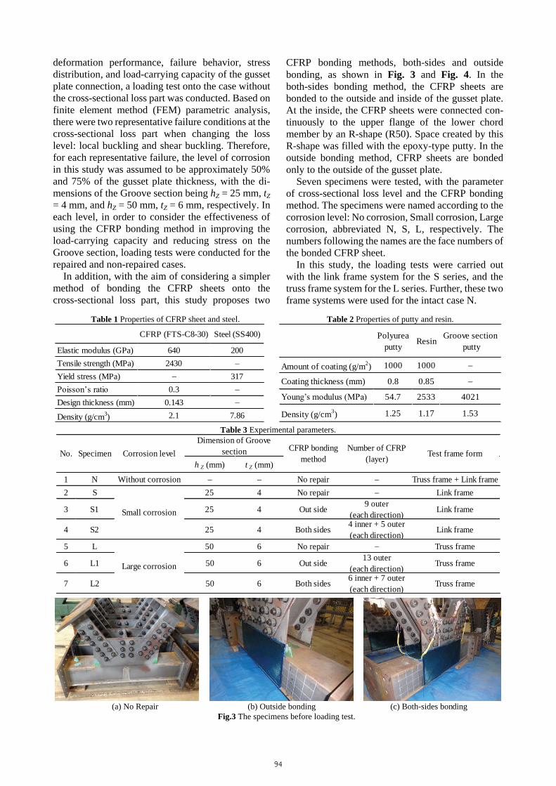
In addition, with the aim of considering a simpler method of bonding the CFRP sheets onto the cross-sectional loss part, this study proposes two
CFRP bonding methods, both-sides and outside bonding, as shown in Fig. 3 and Fig. 4. In the both-sides bonding method, the CFRP sheets are bonded to the outside and inside of the gusset plate. At the inside, the CFRP sheets were connected con-tinuously to the upper flange of the lower chord member by an R-shape (R50). Space created by this R-shape was filled with the epoxy-type putty. In the outside bonding method, CFRP sheets are bonded only to the outside of the gusset plate.
Seven specimens were tested, with the parameter of cross-sectional loss level and the CFRP bonding method. The specimens were named according to the corrosion level: No corrosion, Small corrosion, Large corrosion, abbreviated N, S, L, respectively. The numbers following the names are the face numbers of the bonded CFRP sheet.
In this study, the loading tests were carried out with the link frame system for the S series, and the truss frame system for the L series. Further, these two frame systems were used for the intact case N.
Table 1 Properties of CFRP sheet and steel. Table 2 Properties of putty and resin.
CFRP (FTS-C8-30) Steel (SS400)
Elastic modulus (GPa) 640 200Tensile strength (MPa) 2430 �Yield stress (MPa) � 317Poisson’s ratio 0.3 �Design thickness (mm) 0.143 �
Density (g/cm3) 2.1 7.86
Polyureaputty Resin Groove section
putty
Amount of coating (g/m2) 1000 1000 �
Coating thickness (mm) 0.8 0.85 �
Young’s modulus (MPa) 54.7 2533 4021
Density (g/cm3) 1.25 1.17 1.53 Table 3 Experimental parameters.
h Z (mm) t Z (mm)
1 N Without corrosion � � No repair � Truss frame + Link frame2 S 25 4 No repair � Link frame
3 S1 25 4 Out side 9 outer(each direction) Link frame
4 S2 25 4 Both sides 4 inner + 5 outer(each direction) Link frame
5 L 50 6 No repair � Truss frame
6 L1 50 6 Out side 13 outer(each direction) Truss frame
7 L2 50 6 Both sides 6 inner + 7 outer(each direction) Truss frame
Small corrosion
Large corrosion
No. Specimen Corrosion level CFRP bondingmethod
Number of CFRP(layer)
Dimension of Groovesection Test frame form
(a) No Repair (b) Outside bonding (c) Both-sides bonding
Fig.3 The specimens before loading test.
94
1200
CFRP(Fiber direction: �45)
590
bolt
67
200
5 56
056
200240
64
260
34
Groove
4
1200
CFRP(Fiber direction: �45)
590
bolt
67
200
5 56
056
200240
64
260
3R50
Groove
4
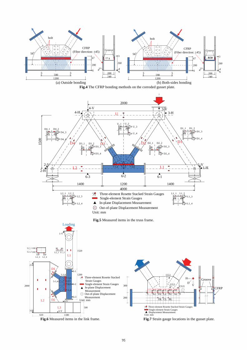
(a) Outside bonding (b) Both-sides bonding Fig.4 The CFRP bonding methods on the corroded gusset plate.
U
D4 D3 D2 D1
L1L2
40001200 1400
2000
1500
U_1 U_2U_3
U_4
D1_1 D1_2D1_3
D1_4
D4_1 D4_2D4_3
D4_4
L2_1 L2_2L2_3
L2_4
L1_1 L1_2L1_3
L1_4
1400
D2_1 D2_2D2_3
D2_4
D3_1 D3_2D3_3
D3_4
50 5050
50 50 50
50
5050 50
50
50
5050
50
50 5050
50
50
50 50
50
50 50 50
50
50
6-26-3 6-1
7-1,4 7-2,5 7-3,6 1-H1-V
2-H
2-V
3-V3-H
4-V4-H
Unit: mm
Three-element Rosette Stacked Strain GaugesSingle-element Strain GaugesIn-plane Displacement MeasurementOut-of-plane Displacement Measurement
Fig.5 Measured items in the truss frame.
1200
1180
1520
500
610
Loading
L1
L2
L3
D1
D2
2000
7-1,4
7-2,5
7-3,65-2,5
5-3,6
5-1,4
80 80
L1_1 L1_2100 100
100
100L2_1
L2_2
L2_3 L2_4
Unit: mm
Three-element Rosette Stacked Strain GaugesSingle-element Strain GaugesIn-plane Displacement Measurement
6-3
6-2
6-1
1-V
2-H
3-H 5-V
4-V
Out-of-plane DisplacementMeasurement
300
2000E2 D2 C2 B2 A21
E1 D1 C1 B1 A1
DL CL BL
VD
H
Unit: mm
Three-element Rosette Stacked Strain GaugesSingle-element Strain GaugesDisplacement Measurement
CG1
CG2CG3
Groove
CFRP
Fig.6 Measured items in the link frame. Fig.7 Strain gauge locations in the gusset plate.
95
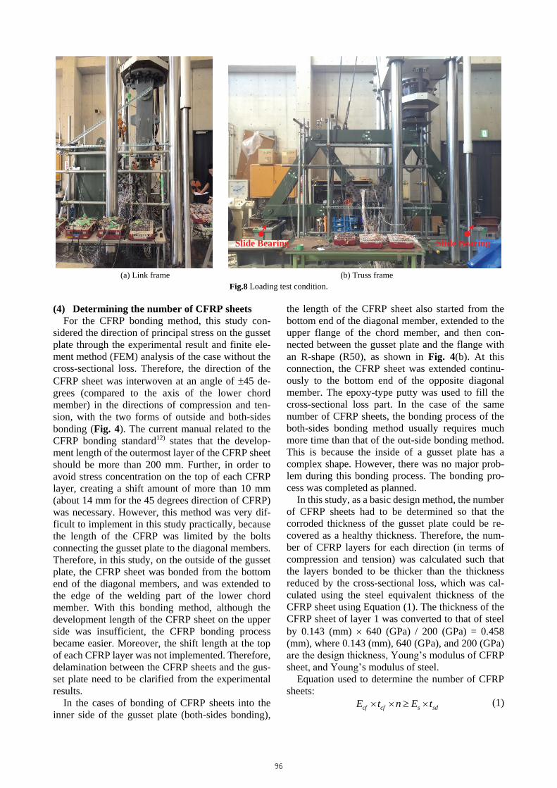
(a) Link frame (b) Truss frame
Fig.8 Loading test condition.
(4) Determining the number of CFRP sheets For the CFRP bonding method, this study con-
sidered the direction of principal stress on the gusset plate through the experimental result and finite ele-ment method (FEM) analysis of the case without the cross-sectional loss. Therefore, the direction of the CFRP sheet was interwoven at an angle of �45 de-grees (compared to the axis of the lower chord member) in the directions of compression and ten-sion, with the two forms of outside and both-sides bonding (Fig. 4). The current manual related to the CFRP bonding standard12) states that the develop-ment length of the outermost layer of the CFRP sheet should be more than 200 mm. Further, in order to avoid stress concentration on the top of each CFRP layer, creating a shift amount of more than 10 mm (about 14 mm for the 45 degrees direction of CFRP) was necessary. However, this method was very dif-ficult to implement in this study practically, because the length of the CFRP was limited by the bolts connecting the gusset plate to the diagonal members. Therefore, in this study, on the outside of the gusset plate, the CFRP sheet was bonded from the bottom end of the diagonal members, and was extended to the edge of the welding part of the lower chord member. With this bonding method, although the development length of the CFRP sheet on the upper side was insufficient, the CFRP bonding process became easier. Moreover, the shift length at the top of each CFRP layer was not implemented. Therefore, delamination between the CFRP sheets and the gus-set plate need to be clarified from the experimental results.
In the cases of bonding of CFRP sheets into the inner side of the gusset plate (both-sides bonding),
the length of the CFRP sheet also started from the bottom end of the diagonal member, extended to the upper flange of the chord member, and then con-nected between the gusset plate and the flange with an R-shape (R50), as shown in Fig. 4(b). At this connection, the CFRP sheet was extended continu-ously to the bottom end of the opposite diagonal member. The epoxy-type putty was used to fill the cross-sectional loss part. In the case of the same number of CFRP sheets, the bonding process of the both-sides bonding method usually requires much more time than that of the out-side bonding method. This is because the inside of a gusset plate has a complex shape. However, there was no major prob-lem during this bonding process. The bonding pro-cess was completed as planned.
In this study, as a basic design method, the number of CFRP sheets had to be determined so that the corroded thickness of the gusset plate could be re-covered as a healthy thickness. Therefore, the num-ber of CFRP layers for each direction (in terms of compression and tension) was calculated such that the layers bonded to be thicker than the thickness reduced by the cross-sectional loss, which was cal-culated using the steel equivalent thickness of the CFRP sheet using Equation (1). The thickness of the CFRP sheet of layer 1 was converted to that of steel by 0.143 (mm) � 640 (GPa) / 200 (GPa) = 0.458 (mm), where 0.143 (mm), 640 (GPa), and 200 (GPa) are the design thickness, Young’s modulus of CFRP sheet, and Young’s modulus of steel.
Equation used to determine the number of CFRP sheets:
cf cf s sdE t n E t� � � � (1)
Slide Bearing Slide Bearing
96
where, Ecf is the elastic modulus of CFRP sheet; tcf is the thickness of a CFRP sheet; n is the necessary number of CFRP sheets; Es is the elastic modulus of the steel; and tsd is the thickness of the cross-sectional loss part of the steel.
For example, in the case having a cross-sectional loss part of 50% of the gusset plate thickness, with tZ = 4 mm, the necessary number of CFRP layers for each direction with the outside bonding method was 4 mm / 0.458 mm = 9 layers. For both-sides bonding, these nine layers were divided evenly between the inside and the outside. In this case, four layers were bonded on the inside and five layers were bonded on the outside, because CFRP sheet bonding on the outside is easier than that on the inside. This was calculated similar to the case with loss part 75% of the gusset plate thickness. This means that the total number of CFRP layers was 6 mm / 0.458 mm = 13 layers, and there were six and seven layers on each side, respectively.
In the CFRP sheet bonding process, the first layer was for the direction of tension or compression, and the second layer for the other direction. This means that the first direction of the gusset plate bonded with the CFRP sheet was able to be tension or compres-sion. This is because the first direction, which was bonded with the CFRP sheet, did not affect the ef-fectiveness of the repair method. The third and fourth layers were a repeat of the first layer and the second layer, respectively.
(5) Measured items a) Strain gauge location
The locations of the strain gauges are shown in Figs. 5, 6, and 7. Four single-element strain gauges were attached to the cross-section of each member of the truss frame and the link frame, in order to con-sider the effects of the two-axis bending moment and the axial force on them. Moreover, in order to de-termine the principal stress components on the cross-sectional loss part and the border line between the gusset plate and the lower chord; three-element 0o/45o/90o Rosette Stacked strain gauges were em-ployed, as shown in Fig. 7. In the non-repaired cases, the strain gauges were attached to the inside and outside of the cross-sectional loss part. In the bond-ing cases of CFRP sheet, the strain gauges were at-tached to the inside of the cross-sectional loss part (steel), and to the outside of the CFRP sheet (Fig. 7). In addition, three-element 0o/45o/90o Rosette Stacked strain gauges were also used at the plate area un-derneath the compressive diagonal member, to grasp the buckling behavior, and single-element strain gauges were used for the other locations.
b) Displacement measurement In each loading step, vertical and horizontal dis-
placements were measured on the members of the truss frame and the link frame, and the bottom sur-face of gusset plate connection, as shown in Fig. 5 and Fig. 6. In addition, the out-of-plane displacement of the gusset plate was also measured at the two outside surfaces of the gusset plate connection. These positions was labeled 7-1~7-6, as shown in Fig. 5 and Fig. 6.
(6) Loading method The loading tests were conducted in the laboratory
with the truss frame system for the large Groove and the link frame system for the small Groove. These frame systems were connected to the specimen by using bolts through the connecting plates. Further, only the specimen was changed after finishing the loading test, and the frame system was kept for the ensuing test.
SHIMADZU experimental equipment with 3000 kN capacity was used to test all specimens. The formal loading test process was only carried out after finishing the repetition about two or three times for the loading test at the elastic phase of the material. The two bottom joints of the truss frame were placed onto the two Teflon plates to allow freedom for the slide bearing. The experimental environment is shown in Fig. 8.
3. RESULTS AND DISCUSSION
As mentioned in Sections 2.(1) and 2.(6), in order to be able to reach the complete failure condition of the specimens under the limited capacity (3000 kN) of the experimental equipment, the link frame and the truss frame were used for the S series and the L se-ries, respectively. Because of the difference in the loading frame forms, in this study, all the following information from the experimental result were eval-uated by using the average axial force of the two diagonal members of the frame connecting directly to the specimen.
(1) Improved effectiveness for max load The maximum loads collected from the experi-
ments are shown in Table 4. The max load reduction rate of the specimens was calculated as the difference between the average axial force of the two diagonal members of the frame of the cases with cross-sectional loss, and that of the case without cross-sectional loss, as in Equation (2). The im-provement rate was taken as the difference in the average axial force of the two diagonal members between the repaired specimen and the non-repaired specimen, as in Equation (3).
97
Determining the max load reduction rate. 0
max max1 0
max
(%) P PRP�
� (2)
where, Pmax is the average axial force of the two diagonal members in the non-repaired case at the max load; and P0
max is the average axial force of the two diagonal members in the intact case N at the max load.
Determining the max load improvement rate. max max
2max
(%) P PRP
� �� (3)
where, P’max is the average axial force of the two diagonal members of the repaired case at the max load; and Pmax is the average axial force of the two diagonal members in the non-repaired case at the max load.
From the information in Table 4, the cases of the L series with the large Groove section, the load-carrying capacity of the non-repaired case L reduced significantly compared to the intact case of N by 74.6%. However, by the two proposed repair methods, their load-carrying capacity increased sig-nificantly, with improvement rates of 55.4% and 74.7%, respectively. Furthermore, with the same number of CFRP sheets, the both-sides bonding method increased the load-carrying capacity by 19%,
compared to the outside bonding method. In the cases of the S series with the small Groove
section, the load-carrying capacity of the non-repaired S case was considerably less than the intact N case by 20.3%. For the two proposed repair methods, their load-carrying capacity increased slightly, with improvement rates of 11.1% and 3.5%, respectively. The difference in the load-carrying capacity between cases S1 and S2 was not consid-erable. This is clarified in Section 3.(3)b).
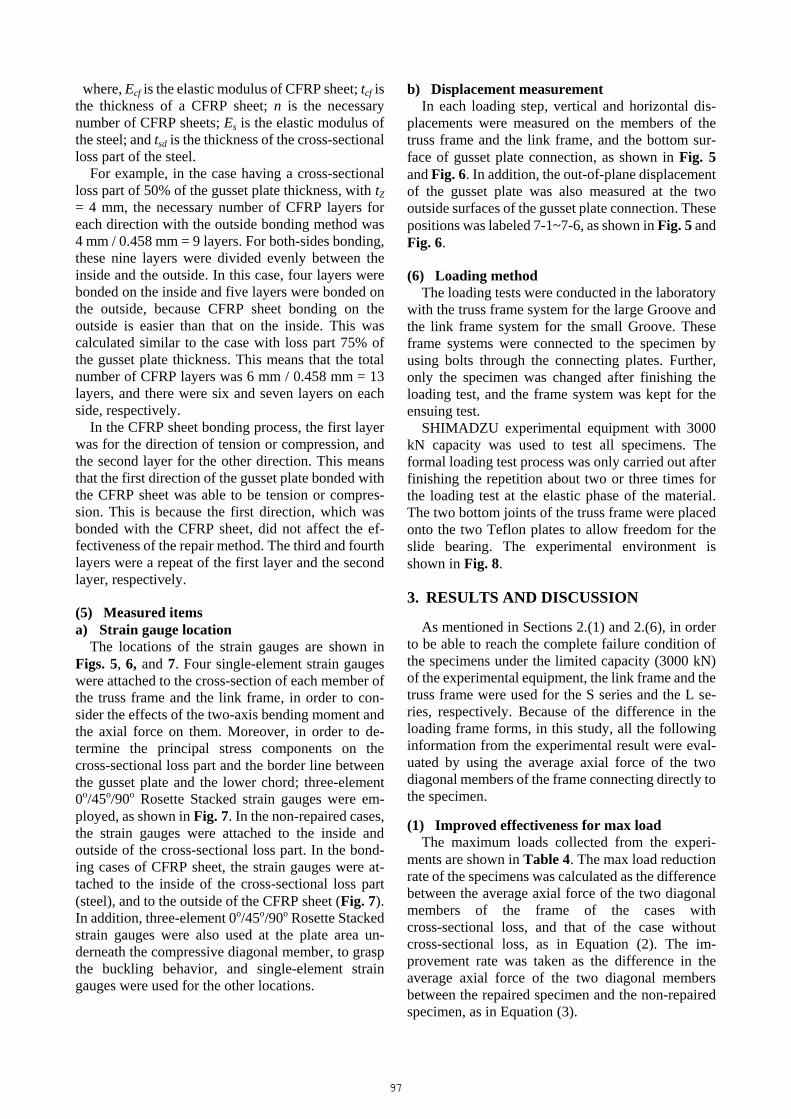
From the experimental results, the reduction of the load-carrying capacity of the gusset plate connection owing to gusset plate corrosion was clarified. Fur-ther, the two proposed repair methods using CFRP sheets significantly improved the load-carrying ca-pacity in the large corrosion cases. However, for the small corrosion cases, their capacity was not im-proved considerably. This is because the delamina-tion between the CFRP sheets and the gusset plate occurred under the large out-of-plane deformation of buckling, which occurred at the plate area underneath the diagonal member of the gusset plate connection and the free edge of the gusset plate, as shown in Fig. 9. Therefore, the load-carrying capacity of the small corrosion cases was not able to increase significantly after this out-of-plane delamination occurred.
(a) S1 (b) S2
Fig.9 Out-of-plane delamination between the CFRP sheet and the gusset plate in the S series. Table 4 Maximum load and improvement rate.
No. Specimen Maximum load(kN)
Max loadreduction rate
R 1(%)
Max loadimprovement rate
R 2(%)Test frame Note
1 N 1634 � � Link frame Without corrosion
2 S 1303 ����� ��������� ��� � Link frame Small corrosion(No repair)
3 S1 1448 � ������ ���� ������ Link frame Small corrosion(Outside bonding)
4 S2 1348 � ������ ���� �������� Link frame Small corrosion(Both-sides bonding)
5 L 415 ����������������� � Truss frame Large corrosion(No repair)
6 L1 645 � (645-415)/415 = 55.4% Truss frame Large corrosion(Out-side bonding)
7 L2 725 � (725-415)/415 = 74.7% Truss frame Large corrosion(Both-sides bonding)
98
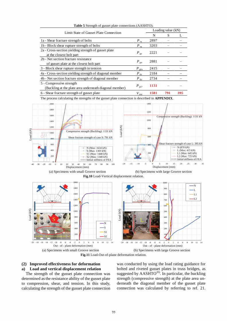
Table 5 Strength of gusset plate connections (AASHTO).
N S L1a - Shear fracture strength of bolts P ru 2897 � �1b - Block shear rupture strength of bolts P ru 3203 � �2a - Cross-section yielding strength of gusset plate at the closest bolt part P gy 2221 � �
2b - Net section fracture resistance of gusset plate at the closest bolt part P gu 2881 � �
3 - Block shear rupture strength in tension P gbs 2415 � �4a - Cross-section yielding strength of diagonal member P dy 2184 � �4b - Net section fracture strength of diagonal member P du 2734 � �5 - Compressive strength (Buckling at the plate area underneath diagonal member) P gcr 1131 � �
6 - Shear fracture strength of gusset plate V gsy 1581 791 395
Loading value (kN)Limit State of Gusset Plate Connection
The process calculating the strengths of the gusset plate connection is described in APPENDIX.
0
200
400
600
800
1000
1200
1400
1600
1800
2000
-40 -30 -20 -10 0 10 20 30 40 50 60 70 80 90 100
Load
(kN
)
Displacement (mm)
N (Max: 1634 kN)S (Max: 1303 kN)S1 (Max: 1448 kN)S2 (Max: 1348 kN)Initial stiffness of FEA
Compressive strength (Buckling): 1131 kN
Shear fracture strength of case S: 791 kN
0
200
400
600
800
1000
1200
1400
-20 -15 -10 -5 0 5 10 15 20 25 30 35
Load
(kN
)
Displacement (mm)
N (870 kN)L (Max: 415 kN)L1 (Max: 645 kN)L2 (Max: 725 kN)Initial stiffness of FEA
Compressive strength (Buckling): 1131 kN
Shear fracture strength of case L: 395 kN
(a) Specimens with small Groove section (b) Specimens with large Groove section
Fig.10 Load-Vertical displacement relation.
0
200
400
600
800
1000
1200
1400
1600
1800
2000
-20 -18 -16 -14 -12 -10 -8 -6 -4 -2 0 2 4 6 8 10 12 14
Load
(kN
)
Out - of - plane deformation (mm)
N
S
S1
S2
S
Local buckling at cross-sectional loss part
0
100
200
300
400
500
600
700
800
900
1000
-20 -18 -16 -14 -12 -10 -8 -6 -4 -2 0 2 4 6 8 10 12 14
Load
(kN
)
Out - of - plane deformation (mm)
N
L
L1
L2
L
(a) Specimens with small Groove section (b) Specimens with large Groove section
Fig.11 Load-Out-of-plane deformation relation.
(2) Improved effectiveness for deformation a) Load and vertical displacement relation
The strength of the gusset plate connection was determined as the resistance ability of the gusset plate to compression, shear, and tension. In this study, calculating the strength of the gusset plate connection
was conducted by using the load rating guidance for bolted and riveted gusset plates in truss bridges, as suggested by AASHTO20). In particular, the buckling strength (compressive strength) at the plate area un-derneath the diagonal member of the gusset plate connection was calculated by referring to ref. 21.
99
This calculation process is described in APPENDIX. In addition, the strength of the gusset plate connec-tion is summarized in Table 5.
The relations between load and vertical displace-ment at the highest point of the tensile link member of the link frame and the lowest central point of the specimens of the truss frame are shown in Fig. 10. The red and blue dashed lines in Fig. 10 express the compressive strength and shear fracture strength of the gusset plate connection, which are summarized in Table 5.
In the S series with the small Groove section, there was almost no change in the initial stiffness. Further, in all cases, buckling at the plate area underneath the diagonal member occurred at approximately 1100 kN (this point is clarified in Section 3.(4)). The vertical displacement of the specimens increased linearly until buckling occurred at the diagonal member. Af-ter overcoming the buckling load, the load-displacement curve trend changed. Moreover, the compressive strength (1131 kN) evaluated by ref. 22 agreed with the load (1100 kN) causing buckling at the plate area underneath the compressive diagonal member of the gusset plate connection from the ex-perimental result.
In the L series with the large Groove section, it was confirmed that the initial stiffness of the case L re-duced considerably compared to the intact case N. Further, in the case of the vertical displacement, the stiffness decreased after shear buckling appeared at the Groove section by about 230 kN. However, with the repair methods using CFRP sheets, its initial stiffness recovered as the case N without cross-sectional loss. This point is clearly seen through cases L1 and L2 bonded CFRP sheet. Fur-thermore, the load-displacement curve trend in these cases is virtually linear until the maximum load is reached.
From the experimental results, the significant re-duction of the initial stiffness in the cases having large corrosion was confirmed. This is unlike the cases having small corrosion, in which there was virtually no change in the initial stiffness. However, in the large corrosion case, with the methods using CFRP sheets, the initial stiffness was recovered to virtually the same level as the intact case. This con-firms that the two proposed repair methods can help to recover the initial stiffness of the corroded gusset plate connection. b) Load and out-of-plane deformation relation
The relations between load and out-of-plane de-formation on the gusset plate are shown in Fig. 11. In Fig. 11(a), the out-of-plane deformation of the intact case N is large only in the phase with virtually maximum load. This is due to the influence of large
deformation induced by buckling at the plate area underneath the compressive diagonal member.
In the S series, the out-of-plane deformation in the non-repaired case S is large. This is due to the in-fluence of local buckling at the Groove section. However, with the CFRP sheet bonding methods, its out-of-plane stiffness increased substantially, and local buckling is prevented at the Groove area. This is clearly seen through the out-of-plane deformation of cases S1 and S2 bonded CFRP sheet, as shown in Fig. 11(a). Their deformation is very small, as in the intact case N, with virtually no change occurring before the maximum load.
In the L series, the asymmetric failure model oc-curred in the non-repaired case L, whereas the failure shape of case S was symmetric. This is understood as mainly because of the influence of the asymmetry of the initial deflection on the gusset plate. This asymmetry of the initial deflection was determined as an inclined shape of the gusset plate based on meas-urements taken directly at the construction site before conducting the loading test. On the other hand, the out-of-plane deformation in the non-repaired case L is large. The cause of this large deformation is the buckling at the Groove section, which caused the gusset plate to fall in the out-of-plane direction when the load increased. However, with the two proposed CFRP bonding methods, the out-of-plane stiffness of case L improved significantly to virtually the same level as that of the intact case N.
These results confirm that the two proposed CFRP bonding methods are also able to recover the out-of-plane stiffness of the corroded gusset plate. (3) Stress distribution a) Principal stress on the gusset plate (steel)
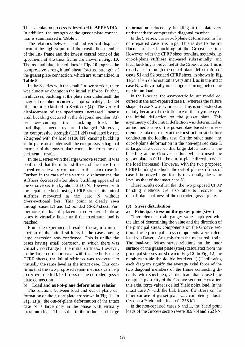
Three-element strain gauges were employed with the aim of determining the value and the direction of the principal stress components on the Groove sec-tion. These principal stress components were calcu-lated via Rosette Analysis from the measured strain. The load-von Mises stress relations on the inner surface of the gusset plate (steel) calculated from the principal stresses are shown in Fig. 12. In Fig. 12, the numbers inside the double brackets “( )” following each diagram signify the average axial force of the two diagonal members of the frame connecting di-rectly with specimen, at the load that caused the complete plasticity of the Groove section. Hereafter, this axial force value is called Yield point load. In the intact case N with the link frame, the stress on the inner surface of gusset plate was completely plasti-cized at a Yield point load of 1258 kN.
In the non-repaired cases S and L, the Yield point loads of the Groove section were 809 kN and 262 kN,
100

respectively. However, with the proposed outside bonding method, the Yield point load of the Groove section increased considerably, to 1046 kN for case S1 and 403 kN for case L1. Furthermore, in the both-sides bonding method, the Groove section was not plasticized completely under the max load. The value of the Yield point load could not be determined in the cases using the both-sided bonding method. Therefore, the Yield point load of the Groove section in these cases was taken as their max load, with 1348 kN for case S2 and 725 kN for case L2.
This confirmed that the two proposed repair methods are able to increase the Yield point load on the corroded section of the gusset plate. Further, in the both-sides bonding method, the corroded section was not plasticized completely under the max load. This is because in the both-sides bonding method, the CFRP sheets were bonded into the inside of the corroded section that improved the eccentric bending moment of the cross-sectional loss part. This can be
explained through the relation between the load and strain on the inner surface of the Groove section in the diagonal direction, as shown in Fig. 13. In the non-repaired cases and the outside bonding cases, because of the eccentric nature of the cross-sectional loss part, the strain of the loss part has reached a large value even under a low loading value.
Figure 14 shows vector diagrams of the principal stress distribution of the Groove section at the 300 kN average axial force of the two diagonal members of the frame, the two diagonal members connecting directly to the specimen. In this figure, the meaning of the red line is compressive stress, and the blue line is tensile stress. The arrows in the figure indicate the loading direction onto the Groove section. The note at the bottom left states the unit used in the diagram. From this vector diagram, the direction of the prin-cipal stress of the corroded section of the gusset plate was confirmed to be about 45 degrees.
0
200
400
600
800
1000
1200
1400
1600
1800
2000
0 200 400 600 800 1000 1200 1400 1600 1800 2000
Load
(kN
)
Von Mises Stress (N/mm2)
E1 D1 C1 B1 A1
Yield Point
E1 D1 C1 B1 A1
0
200
400
600
800
1000
1200
1400
1600
1800
2000
0 200 400 600 800 1000 1200 1400 1600 1800 2000
Load
(kN
)
Von Mises Stress (N/mm2)
E1 D1 C1 B1 A1
Yield Point
E1 D1 C1 B1 A1
0
200
400
600
800
1000
1200
1400
1600
1800
2000
0 200 400 600 800 1000 1200 1400 1600 1800 2000
Load
(kN
)
Von Mises Stress (N/mm2)
E1 D1 C1 B1 A1
Yield Point
E1 D1 C1 B1 A1
0
200
400
600
800
1000
1200
1400
1600
1800
2000
0 200 400 600 800 1000 1200 1400 1600 1800 2000Lo
ad (k
N)
Von Mises Stress (N/mm2)
D1 B1
Yield Point
E1 D1 C1 B1 A1
N (1258 kN) S (809 kN) S1 (1046 kN) S2 (1348 kN)
(a) Specimens with link frame (S series) (--): Yield point load (kN)
0
100
200
300
400
500
600
700
800
900
1000
0 50 100 150 200 250 300 350 400
Load
(kN
)
Von Mises Stress (N/mm2)
E1 D1 C1 B1 A1
Yield Point
E1 D1 C1 B1 A1
0
100
200
300
400
500
600
700
800
900
1000
0 200 400 600 800 1000 1200 1400 1600 1800 2000
Load
(kN
)
Von Mises Stress (N/mm2)
E1 D1 C1 B1 A1
Yield Point
E1 D1 C1 B1 A1
0
100
200
300
400
500
600
700
800
900
1000
0 200 400 600 800 1000 1200 1400 1600 1800 2000
Load
(kN
)
Von Mises Stress (N/mm2)
E1 D1 C1 B1 A1
Yield Point
E1 D1 C1 B1 A1
0
100
200
300
400
500
600
700
800
900
1000
0 200 400 600 800 1000 1200 1400 1600 1800 2000
Load
(kN
)
Von Mises Stress (N/mm2)
D1 B1
Yield Point
E1 D1 C1 B1 A1
N L (262 kN) L1 (403 kN) L2 (725 kN)
(b) Specimens with truss frame (L series) (--): Yield point load (kN) Fig.12 Load-Von Mises stress on the inner surface of the gusset plate (steel).
0
200
400
600
800
1000
1200
1400
1600
-10000 -5000 0 5000 10000 15000 20000 25000 30000 35000 40000
Load
(kN
)
Strain (�)
NSS1S2
B1
Strain in diagonal direction
Fig.13 Load-Strain relation on the inner surface of the Groove section in the diagonal direction.
101
A1B1C1D1E1
1 N/mm2
A1B1C1D1E1
1 N/mm2
A1B1C1D1E1
1 N/mm2
A1B1C1D1E1
1 N/mm2 N S S1 S2
(a) Specimens with link frame
A1B1C1D1E1
1 N/mm2
A1B1C1D1E1
50 N/mm2
A1B1C1D1E1
20 N/mm2
A1B1C1D1E1
10 N/mm2 N L L1 L2
(b) Specimens with truss frame Fig.14 Principal stress on the inner surface of the gusset plate (steel) (at 300 kN of the diagonal frame member).
0
200
400
600
800
1000
1200
1400
1600
1800
2000
0 500 1000 1500 2000 2500 3000
Load
(kN
)
Von Mises Stress (N/mm2)
E1 D1 C1 B1 A1
Tensile Strength
E1 D1 C1 B1 A1
1386 kN
0
200
400
600
800
1000
1200
1400
1600
1800
2000
0 500 1000 1500 2000 2500 3000
Load
(kN
)
Von Mises Stress (N/mm2)
E1 D1 C1 B1 A1
Tesile Strength
E1 D1 C1 B1 A1
1329 kN
S1 (1386 kN) S2 (1329 kN)
(a) Specimens with link frame (S series) (--): Delamination Load (kN)
0
100
200
300
400
500
600
700
800
900
1000
0 500 1000 1500 2000 2500 3000
Load
(kN
)
Von Mises Stress (N/mm2)
E1 D1 C1 B1 A1
Tensile Strength
E1 D1 C1 B1 A1
627 kN
0
100
200
300
400
500
600
700
800
900
1000
0 500 1000 1500 2000 2500 3000
Load
(kN
)
Von Mises Stress (N/mm2)
E1 D1 C1 B1 A1
Tensile Strength
E1 D1 C1 B1 A1
721 kN
L1 (627 kN) L2 (721 kN)
(b) Specimens with truss frame (L series) (--): Delamination Load (kN) Fig.15 Load-Von Mises stress on CFRP sheet.
Table 6 The rate between bending moment stress and axis force stress on members of the frames (at max load). N S S2 L1 L2
� Mz � Nx 0.29 0.07 0.28 0.19 0.10� My � Nx 0.15 0.05 0.07 0.07 0.03� Mz � Nx 0.26 0.3 0.35 0.12 0.12� My � Nx 0.25 0.21 0.08 0.09 0.11
SpecimenCompressive
diagonal member
Tensilediagonal member
Mz, My, Nx are in-plane bending moment, out-of-plane bending moment, and axial force, respectively.
b) Principal stress on the CFRP sheet Figure 15 shows the relations between load and
von Mises stress on the outermost CFRP sheet of the Groove section. In this figure, the red horizontal line indicates the load (delamination load), which caused
delamination between the CFRP sheet and the gusset plate. The delamination load was determined at the loading value, with the stress on the outermost CFRP sheet substantially lower. The numbers following each diagram in Fig. 15 indicate the delamination
102

load. Figure 15 reveals that the CFRP sheet in all of the cases worked on the elastic phase. Further, the delamination load was approximately equal to the max load in each case. This confirms that the de-lamination occurred between the CFRP sheet and the gusset plate, the load-carrying capacity of the specimens could not increase beyond that point. The delamination load in cases S1 and S2 were almost the same, with values of 1386 kN and 1329 kN. This confirms that the difference in the load-carrying ca-pacity between S1 and S2 was not considerable. c) Bending stress on members of the frame
Four single-element strain gauges were attached to the cross-section of each member of the link frame and the truss frame, in order to consider the effects of the two-axis bending moment and the axial force on them. The rate between the bending moment stress and the axial force stress on the cross-section of two diagonal members of the frame, which were con-nected directly to the specimen, is listed in Table 6. From Table 6, the average rate of bending moment stress/ axis force stress in the cases with the link frame was larger than that of the truss frame; such as 25% for the S series, and 13% for the L series. This is because the connecting sections between all the members of the truss system are considered as joints in the experimental environment; whereas, the con-necting sections of the members of the link system are considered as completely hard. Therefore, it is not difficult to conclude that with the same specimen, its load-carrying capacity with the link frame is lower than that of the truss frame. However, the difference between both these load-carrying capacities is not large. This is because the axial force stress on the cross-section of members of the frames was more superior compared to the bending stress on them in all of the cases.
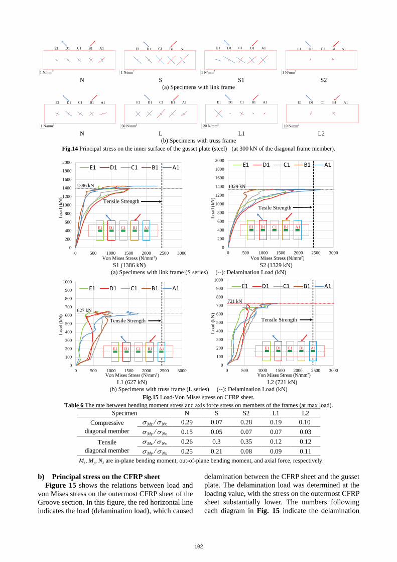
(4) Failure condition a) Final shape of the specimen
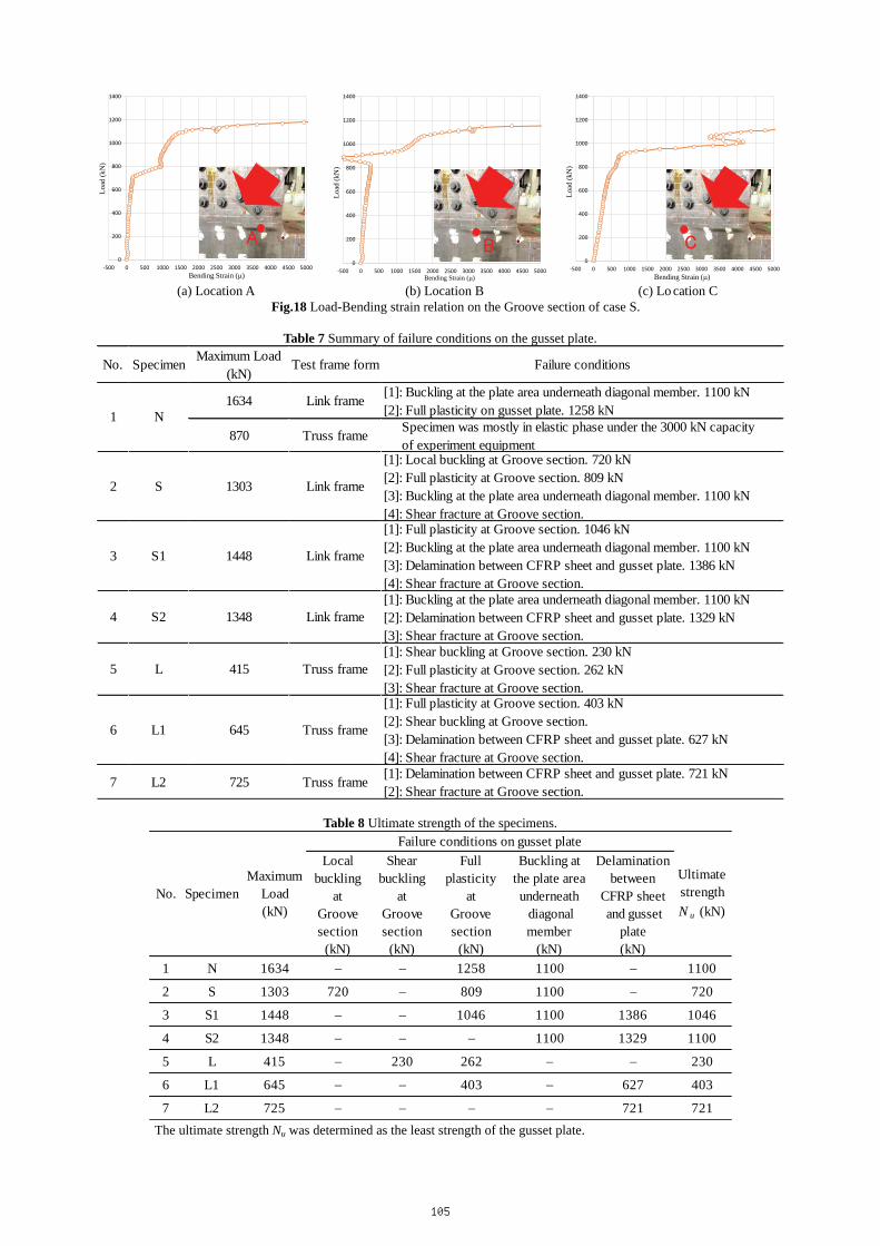
Figure 16 shows the residual deformation of the specimens after the loading test, and Table 7 lists all of the failure conditions on the gusset plate in each case in order. In the intact case N with the link frame, the first failure condition was buckling at the plate area underneath the diagonal member from 1100 kN. This was clarified through the relation between the load and the bending strain of the plate area under-neath the compressive diagonal member, as shown in Fig. 17. On the other hand, the load causing buckling in this plate area was similar to the S series, and was irrespective of whether it was the repaired or non-repaired condition. Further, the load-carrying capacity of the intact case N reached the maximum value after the large out-of-plane deformation oc-curred at the plate area underneath the compressive
diagonal member owing to buckling. In the non-repaired case S, local buckling appeared
at the Groove section for 720 kN. This is understood to be as a result of eccentricity, due to the decreased thickness of the Groove section, which caused a significant increase in the bending moment in the compressive direction of the Groove section. This point is clarified through the relation between the load and bending strain on the Groove section, as shown in Fig. 18. The final failure condition in this case was the shear fracture at the Groove section. On the other hand, the two proposed CFRP sheet bond-ing methods increased the out-of-plane stiffness of the gusset plate. Consequently, in cases S1 and S2, local buckling did not occur. In addition, although the low elastic putty material was applied, delamination occurred between CFRP sheet and the gusset plate. Specifically, under the large out-of-plane defor-mation of the free edge of the gusset plate during compression and the very large out-of-plane stiffness of the CFRP sheets, deformation of the putty layer exceeded its plastic limit. Therefore, the CFRP sheet and the gusset plate were rapidly delaminated. Moreover, because of this delamination in the free edge of the gusset plate, the load-carrying capacity of the S series did not improve significantly. The final status in cases S1 and S2 was delamination and shear fracture at the Groove section.
In the non-repaired case L, unlike in case S, shear buckling occurred at the Groove section. This is understood to be because the height/thickness of the Groove section was comparatively large, which re-duced the shear buckling strength of this section. The final failure status in this case was a large defor-mation due to shear buckling and shear fracture, as shown in Fig. 16(b). In case L1 with the outside bonding method, although the CFRP sheet was bonded into the loss part, shear buckling occurred. On the other hand, with the efficiency of reducing the eccentricity at the Groove section, and improvement of the shear buckling strength by the both-sides method, shear buckling did not occur in case L2. Therefore, its load-carrying capacity increased sig-nificantly compared to those of cases L and L1. The final failure status in this case was delamination and shear fracture at the Groove section.
As a result, by the both-side bonding method, local buckling or shear buckling at the corroded section is prevented. In contrast, in the outside bonding method, shear buckling is not effectively prevented in the large corrosion case. Further, the final failure status of the corroded gusset plate connection after using the CFRP bonding methods is shear fracture at the corroded section, and delamination between the CFRP sheet and gusset plate. Furthermore, the failure
103
[1]
[1]: Buckling at the plate area underneath diagonalmember[2]: Full plasticity on gusset plate
[1] [1] [3][4][1]: Local buckling at Groove section[2]: Full plasticity at Groove section[3]: Buckling at the plate area underneath diagonal member[4]: Shear fracture at Groove section
[3]
N (1634 kN) S (1303 kN)
[4] [3][1]: Full plasticity at Groove section[2]: Buckling at the plate area underneath diagonal member[3]: Delamination between CFRP sheet and gusset plate[4]: Shear fracture at Groove section
[2] [2][2][3] [1]
[1]: Buckling at the plate area underneath diagonal member[2]: Delamination between CFRP sheet and gusset plate[3]: Shear fracture at Groove section
[1]
S1 (1448 kN) S2 (1348 kN)
(a) Specimens with link frame (S series) Fig.16a Final shape of the specimens with small Groove section. (--): Maximum Load (kN)
[1][3]
[1]: Shear buckling at Groove section[2]: Full plasticity at Groove section[3]: Shear fracture at Groove section
[1]
N (870 kN) L (415 kN)
[2][3]
[1]: Full plasticity at Groove section[2]: Shear buckling at Groove section[3]: Delamination of CFRP and gusset plate[4]: Shear fracture at Groove section
[4] [2] [1]
[1]: Delamination between CFRP sheet andgusset plate[2]: Shear fracture at Groove section
L1 (645 kN) L2 (725 kN) (b) Specimens with truss frame (L series)
Fig.16b Final shape of the specimens with large Groove section. (--): Maximum Load (kN)
0
200
400
600
800
1000
1200
1400
1600
1800
2000
-10000 -5000 0 5000 10000 15000 20000
Load
(kN
)
Bending Strain (�) 0
200
400
600
800
1000
1200
1400
1600
1800
2000
-10000 -5000 0 5000 10000 15000 20000
Load
(kN
)
Bending Strain (�) 0
200
400
600
800
1000
1200
1400
1600
1800
2000
-10000 -5000 0 5000 10000 15000 20000
Load
(kN
)
Bending Strain (�) (a) N (b) S (c) S2 Fig.17 Load-Bending strain relation at the plate area underneath the diagonal member.
104
0
200
400
600
800
1000
1200
1400
-500 0 500 1000 1500 2000 2500 3000 3500 4000 4500 5000
Load
(kN
)
Bending Strain (�) 0
200
400
600
800
1000
1200
1400
-500 0 500 1000 1500 2000 2500 3000 3500 4000 4500 5000
Load
(kN
)
Bending Strain (�) 0
200
400
600
800
1000
1200
1400
-500 0 500 1000 1500 2000 2500 3000 3500 4000 4500 5000
Load
(kN
)
Bending Strain (�) (a) Location A (b) Location B (c) Lo cation C
Fig.18 Load-Bending strain relation on the Groove section of case S.
Table 7 Summary of failure conditions on the gusset plate.
No. Specimen Maximum Load(kN)
Test frame form Failure conditions
1634 Link frame [1]: Buckling at the plate area underneath diagonal member. 1100 kN[2]: Full plasticity on gusset plate. 1258 kN
870 Truss frame Specimen was mostly in elastic phase under the 3000 kN capacity of experiment equipment
2 S 1303 Link frame
[1]: Local buckling at Groove section. 720 kN[2]: Full plasticity at Groove section. 809 kN[3]: Buckling at the plate area underneath diagonal member. 1100 kN[4]: Shear fracture at Groove section.
3 S1 1448 Link frame
[1]: Full plasticity at Groove section. 1046 kN[2]: Buckling at the plate area underneath diagonal member. 1100 kN[3]: Delamination between CFRP sheet and gusset plate. 1386 kN[4]: Shear fracture at Groove section.
4 S2 1348 Link frame[1]: Buckling at the plate area underneath diagonal member. 1100 kN[2]: Delamination between CFRP sheet and gusset plate. 1329 kN[3]: Shear fracture at Groove section.
5 L 415 Truss frame[1]: Shear buckling at Groove section. 230 kN[2]: Full plasticity at Groove section. 262 kN[3]: Shear fracture at Groove section.
6 L1 645 Truss frame
[1]: Full plasticity at Groove section. 403 kN[2]: Shear buckling at Groove section.[3]: Delamination between CFRP sheet and gusset plate. 627 kN[4]: Shear fracture at Groove section.
7 L2 725 Truss frame [1]: Delamination between CFRP sheet and gusset plate. 721 kN[2]: Shear fracture at Groove section.
N1
Table 8 Ultimate strength of the specimens.
Localbuckling
atGroovesection
(kN)
Shearbuckling
atGroovesection
(kN)
Fullplasticity
atGroovesection
(kN)
Buckling atthe plate areaunderneath diagonalmember
(kN)
Delaminationbetween
CFRP sheet and gusset
plate(kN)
1 N 1634 � � 1258 1100 � 1100
2 S 1303 720 � 809 1100 � 720
3 S1 1448 � � 1046 1100 1386 1046
4 S2 1348 � � � 1100 1329 1100
5 L 415 � 230 262 � � 230
6 L1 645 � � 403 � 627 403
7 L2 725 � � � � 721 721
No. SpecimenMaximum
Load(kN)
UltimatestrengthN u (kN)
Failure conditions on gusset plate
The ultimate strength Nu was determined as the least strength of the gusset plate.
105
behavior of the corroded gusset plate depended on the size of the corroded section. Specifically, local buckling was seen in the small corrosion case, and shear buckling was seen in the large corrosion case. Therefore, it is necessary to conduct a parametric analysis of the size of the corroded section using FEM in further research. b) Final shape of the CFRP sheet
From the relation between load and stress on the outermost CFRP sheet of the S series and the L series, summarized in Fig. 15, it was confirmed that all of CFRP sheets worked on the elastic phase. In addition, because the out-of-plane stiffness of the bonded CFRP sheets was quite large, the surface shape of the CFRP sheet bonded onto the outside of the gusset plate showed virtually no change during the loading test. Further, in all the cases with the bonded CFRP sheet, although the low elastic putty material was used, delamination occurred between the gusset plate and the CFRP sheet. (5) Improved effectiveness for ultimate strength
Table 8 lists all the failure conditions on the gusset plate in each case. It includes local buckling at the Groove section, shear buckling at the Groove section, full plasticity at the Groove section, buckling at the plate area underneath the compressive diagonal member, and delamination between the CFRP sheet and the gusset plate. The ultimate strength of each case was determined as the least resistance ability of the gusset plate in compression, tension, shear frac-ture, delamination, and full plasticity of loss part. From the ultimate strength summarized in Table 8, it is clear that using the proposed CFRP bonding methods increases the strength of the corroded gusset plate. In particular, the effectiveness for increasing the strength of the gusset plate in the cases employing the both-sides bonding method was greater than that of the case using the outside bonding method. This is because of the efficiency of this method for pre-venting buckling of the Groove, and increasing the Yield point load at this section. On the other hand, in the S series, although use of the two repair methods did not substantially improve the load-carrying ca-pacity of the gusset plate, the proposed methods were able to increase the strength of the gusset plate ef-fectively.
From the information summarized above, it is clear that applying the two proposed repair methods substantially increases the strength of the corroded gusset plate.
4. CONCLUSION
This study proposes two repair methods using carbon fiber-reinforced polymers (CFRP) for cor-
roded gusset plate connections after investigating their effectiveness, with the simpler CFRP bonding process for the outside bonding method and the im-proved eccentricity of the corroded section for the both-sides bonding method. Evaluations were con-ducted by implementing the two bonding methods with CFRP sheets and evaluating the improvement rate of the strength of the corroded gusset plate. Specifically, loading tests in the laboratory with a model approximately 50% the size of the real bridge, and the degree of corrosion assumed about 50% and 75% of the gusset plate thickness, were conducted. The results obtained from this study are summarized as follows:
(1) Significant reduction of the initial stiffness and increased out-of-plane deformation of the gusset plate owing to the gusset plate corrosion were con-firmed. Subsequently, using the two proposed repair methods for applying CFRP sheets, the initial stiff-ness was recovered to virtually the same as that of the intact case. Further, these two methods were also confirmed to be able to prevent out-of-plane defor-mation of the corroded gusset plate connection.
(2) Reduction in the load-carrying capacity of the gusset plate connection, owing to the gusset plate corrosion, was clarified. The two proposed repair methods using CFRP sheet significantly improved the load-carrying capacity in the large corrosion cases. Conversely, the capacity of the small corrosion cases was not improved considerably. This is because out-of-plane delamination between the CFRP sheet and the gusset plate occurred under the large buck-ling deformation at the plate area underneath the compressive diagonal member.
(3) The experimental results show that the two proposed repair methods can increase the Yield point load on the corroded section of the gusset plate. Furthermore, in the both-sides bonding method, the corroded section was not plasticized completely un-der the maximum load. This is because in the both-sides bonding method, the CFRP sheets were bonded into the inside of the corroded section, which improved the eccentric bending moment of the cross-sectional loss part.
(4) The experimental results also reveal that ap-plying the two proposed repair methods substantially increases the strength of the corroded gusset plate. Further, in the small corrosion case, although the two repair methods did not considerably improve the load-carrying capacity of the gusset plate, the methods were able to increase the strength of the gusset plate significantly.
In further research, it will be necessary to conduct parametric analysis with the size of the corrosion section of the gusset plate using FEM in order to clarify the failure behavior, the reduction rate of the
106
load-carrying capacity, and the improvement rate of the load-carrying capacity of the corroded gusset plate connection after using the CFRP sheet. In ad-dition, establishing the details of the design method using CFRP sheets for corroded gusset plate con-nection is needed, such as the optimum number of CFRP sheet, the bonding method, and the location bonding CFRP. APPENDIX: CALCULATING STRENGTH
OF GUSSET PLATE CON- NECTION (AASHTO)
In this study, calculation of the strength of the
gusset plate connection was conducted by using the load rating guidance of the gusset plate, as suggested
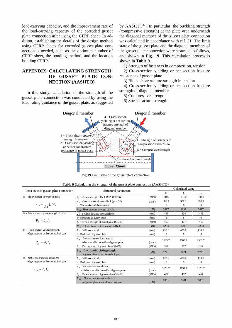
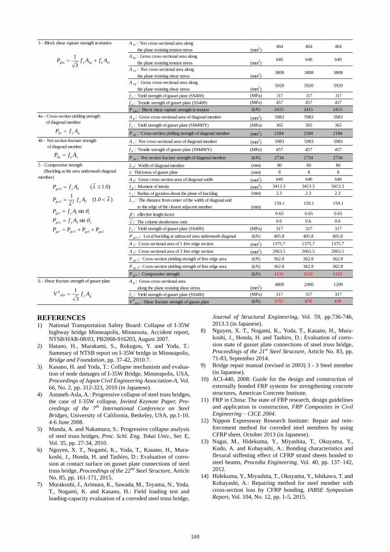
by AASHTO20). In particular, the buckling strength (compressive strength) at the plate area underneath the diagonal member of the gusset plate connection was calculated in accordance with ref. 21. The limit state of the gusset plate and the diagonal members of the gusset plate connection were assumed as follows, and shown in Fig. 19. This calculation process is shown in Table 9.
1) Strength of fasteners in compression, tension 2) Cross-section yielding or net section fracture
resistance of gusset plate 3) Block shear rupture strength in tension 4) Cross-section yielding or net section fracture
strength of diagonal member 5) Compressive strength 6) Shear fracture strength
Lower Chord
1 Strength of fasteners in compression and tension
3 Block shear rupture strength in tension
2 Cross-section yielding or net section fracture
resistance of gusset plate
4 Cross-section yielding or net section
fracture strength of diagonal member
6 Shear fracture strength
5 Compressive strength
Diagonal memberDiagonal member
Fig.19 Limit state of the gusset plate connection.
Table 9 Calculating the strength of the gusset plate connection (AASHTO).
N S Lf u : Tensile strength of bolt (M20(F10T)) (MPa) 1100 1100 1100A r : Cross-sectional area of bolt (� = 22) (mm2) 380.1 380.1 380.1n: The number of shear planes 6 6 6P ru : Shear fracture strength of bolts (kN) 2897 2897 2897ΣL c : Clear distance between holes (mm) 438 438 438t: Thickness of gusset plate (mm) 8 8 8f u : Tensile strength of gusset plate (SS400) ---- (MPa) 457 457 457P ru : Block shear rupture strength of bolts (kN) 3203 3203 3203L e : Whitmore width (mm) 438.0 438.0 438.0t: Thickness of gusset plate (mm) 8 8 8A e : Gross cross-sectional area of Whitmore effective width of gusset plate (mm2)
3503.7 3503.7 3503.7
f y : Yield strength of gusset plate (SS400) (MPa) 317 317 317P gy : Cross-section yielding strength of gusset plate at the closest bolt part
(kN) 2221 2221 2221
L e : Whitmore width (mm) 438.0 438.0 438.0t: Thickness of gusset plate (mm) 8 8 8A s : Net cross-sectional area of Whitmore effective width of gusset plate - (mm2)
3151.7 3151.7 3151.7
f u : Tensile strength of gusset plate (SS400) (MPa) 457 457 457P gu : Net section fracture resistance of gusset plate at the closest bolt part - (kN)
2881 2881 2881
2b - Net section fracture resistance of gusset plate at the closest bolt part
2a - Cross-section yielding strength of gusset plate at the closest bolt part
Limit state of gusset plate connection Calculated value
1a - Shear fracture strength of bolts
1b - Block shear rupture strength of bolts
Structural parameters
yegy fAP �
usgu fAP �
ruru nAfP3
1�
ucru tfLP �
107
A tn : Net cross-sectional area along the plane resisting tension stress (mm2)
464 464 464
A tg : Gross cross-sectional area along the plane resisting tension stress (mm2)
640 640 640
A vn : Net cross-sectional area along the plane resisting shear stress (mm2)
3808 3808 3808
A vg : Gross cross-sectional area along the plane resisting shear stress (mm2)
5920 5920 5920
f y : Yield strength of gusset plate (SS400) (MPa) 317 317 317
f u : Tensile strength of gusset plate (SS400) (MPa) 457 457 457P gbs : Block shear rupture strength in tension (kN) 2415 2415 2415A g : Gross cross-sectional area of diagonal member (mm2) 5983 5983 5983
f y : Yield strength of gusset plate (SM490Y) (MPa) 365 365 365
P dy : Cross-section yielding strength of diagonal member (mm2) 2184 2184 2184
A s : Net cross-sectional area of diagonal member (mm2) 5983 5983 5983
f u : Tensile strength of gusset plate (SM490Y) (MPa) 457 457 457
P du : Net section fracture strength of diagonal member (kN) 2734 2734 2734
L 0: Width of diagonal member (mm) 80 80 80t: Thickness of gusset plate (mm) 8 8 8A 0: Gross cross-section area of diagonal width (mm2) 640 640 640I g : Moment of inertia (mm4) 3413.3 3413.3 3413.3r s : Radius of gyration about the plane of buckling (mm) 2.3 2.3 2.3L c : The distance from center of the width of diagonal end to the edge of the closest adjacent member (mm)
159.1 159.1 159.1
� : effective length factor 0.65 0.65 0.65
� : The column slenderness ratio 0.6 0.6 0.6f y : Yield strength of gusset plate (SS400) (MPa) 317 317 317P gcr 1: Local buckling at unbraced area underneath diagonal (kN) 405.8 405.8 405.8A 1: Cross-sectional area of 1 free edge section (mm2) 1375.7 1375.7 1375.7A 2: Cross-sectional area of 2 free edge section (mm2) 2063.5 2063.5 2063.5P gy 1: Cross-section yielding strength of free edge area (kN) 362.8 362.8 362.8P gy 2: Cross-section yielding strength of free edge area (kN) 362.8 362.8 362.8P gcr : Compressive strength (kN) 1131 1131 1131A g : Gross cross-sectional area along the plane resisting shear stress (mm2)
4800 2400 1200
f y : Yield strength of gusset plate (SS400) (MPa) 317 317 317V 0
gsy : Shear fracture strength of gusset plate (kN) 1757 878 439
3 - Block shear rupture strength in tension
4a - Cross-section yielding strength of diagonal member
4b - Net section fracture strength of diagonal member
6 - Shear fracture strength of gusset plate
5 - Compressive strength (Buckling at the area underneath diagonalmember)
tnuvgygbs AfAfP ��3
1
gydy AfP �
sudu AfP �
211
222
111
021
01
sin
sin
)0.1(1
)0.1(
gygygcrgcr
ygy
ygy
ygcr
ygcr
PPPPAfPAfP
AfP
AfP
���
�
�
��
��
�
�
��
�
gygsy AfV3
10 �
REFERENCES 1) National Transportation Safety Board: Collapse of I-35W
highway bridge Minneapolis, Minnesota, Accident report, NTSB/HAR-08/03, PB2008-916203, August 2007.
2) Hatano, H., Murakami, S., Rokugou, Y. and Yoda, T.: Summary of NTSB report on I-35W bridge in Minneapolis, Bridge and Foundation, pp. 37-42, 2010.7.
3) Kasano, H. and Yoda, T.: Collapse mechanism and evalua-tion of node damages of I-35W Bridge, Minneapolis, USA, Proceedings of Japan Civil Engineering Association-A, Vol. 66, No. 2, pp. 312-323, 2010 (in Japanese).
4) Astaneh-Asla, A.: Progressive collapse of steel truss bridges, the case of I-35W collapse, Invited Keynote Paper, Pro-ceedings of the 7th International Conference on Steel Bridges, University of California, Berkeley, USA, pp.1-10, 4-6 June 2008.
5) Manda, A. and Nakamura, S.: Progressive collapse analysis of steel truss bridges, Proc. Schl. Eng. Tokai Univ., Ser. E, Vol. 35, pp. 27-34, 2010.
6) Nguyen, X. T., Nogami, K., Yoda, T., Kasano, H., Mura-koshi, J., Honda, H. and Tashiro, D.: Evaluation of corro-sion at contact surface on gusset plate connections of steel truss bridge, Proceedings of the 22nd Steel Structure, Article No. 85, pp. 161-171, 2015.
7) Murakoshi, J., Arimura, K., Sawada, M., Toyama, N., Yoda, T., Nogami, K. and Kasano, H.: Field loading test and loading-capacity evaluation of a corroded steel truss bridge,
Journal of Structural Engineering, Vol. 59, pp.736-746, 2013.3 (in Japanese).
8) Nguyen, X. T., Nogami, K., Yoda, T., Kasano, H., Mura-koshi, J., Honda, H. and Tashiro, D.: Evaluation of corro-sion state of gusset plate connections of steel truss bridge, Proceedings of the 21st Steel Structure, Article No. 83, pp. 71-83, September 2014.
9) Bridge repair manual (revised in 2003) 3 - 3 Steel member (in Japanese).
10) ACI-440, 2008: Guide for the design and construction of externally bonded FRP systems for strengthening concrete structures, American Concrete Institute.
11) FRP in China: The state of FRP research, design guidelines and application in construction, FRP Composites in Civil Engineering – CICE 2004.
12) Nippon Expressway Research Institute: Repair and rein-forcement method for corroded steel members by using CFRP sheet, October 2013 (in Japanese).
13) Nagai, M., Hidekuma, Y., Miyashita, T., Okuyama, Y., Kudo, A. and Kobayashi, A.: Bonding characteristics and flexural stiffening effect of CFRP strand sheets bonded to steel beams, Procedia Engineering, Vol. 40, pp. 137–142, 2012.
14) Hidekuma, Y., Miyashita, T., Okuyama, Y., Ishikawa, T. and Kobayashi, A.: Repairing method for steel member with cross-section loss by CFRP bonding, IABSE Symposium Report, Vol. 104, No. 12, pp. 1-5, 2015.
108
15) Wakabayashi, D., Miyashita, T., Okuyama, Y., Nagai, M., Koide, N., Kobayashi, A., Hidekuma, Y. and Horimoto, W.: Experimental study on repair and reinforcement method for web in steel girder bridge using FRP, the 9th Symposium on Research and Application of Hybrid Structures, pp. 371-378, 2011 (in Japanese).
16) Miyashita, T. and Nagai, M.: Repair method for corroded steel girder ends using CFRP sheet, IABSE-JSCE Joint Conference on Advances in Bridge Engineering-III, 21-22 August, 2015, Dhaka, Bangladesh.
17) Okuyama, Y., Miyashita, T., Wakabayashi, D., Hidekuma, Y., Kobayashi, A., Koide, N., Horimoto, W. and Nagai, M.: A study on optimum design method of repair and rein-forcement method using carbon fiber sheets for corroded web in steel girder bridge, Proceedings of Structural En-gineering, Vol. 60A, pp. 541–553, March 2014 (in Japa-nese).
18) Wakabayashi, D., Miyashita, T., Okuyama, Y., Kobayashi, A. and Hidekuma, Y.: Repair method using CFRP for cor-roded steel girder ends, Fourth Asia-Pacific Conference on FRP in Structures (APFIS 2013), pp.1-6, 11-13 December 2013.
19) Miyashita, T., Wakabayashi, D., Hidekuma, Y., Kobayashi, A., Okuyama, Y., Koide, N., Horimoto, W. and Nagai, M.: CFRP repair method for corroded steel girder ends, IABSE Symposium Report, Vol. 104, No. 12, pp. 1-7, August 2015.
20) Federal Highway Administration: Load rating guidance and examples for bolted and riveted gusset plate in truss bridges, Publication No. FHWA-IF-09-014, 2009.
21) Murakoshi, J., Tashiro, D., Enomoto, T., Nogami, K., Yoda, T. and Kasano, H.: Study on evaluation equation for local buckling strength of gusset plate connection in truss bridge, JSCE 69th Annual Conference, pp. 1223-1224, 2014.9 (in Japanese).
22) Miyashita, T., Iwasaki, E., Nagai, M. and Khanh, T. D.: On-site loading test and short-term monitoring for Gerber steel truss bridges being used for 76 years, Journal of Structural Engineering, Vol. 61A, pp. 439-450, 2015 (in Japanese).
23) Okuyama, Y., Miyashita, T., Ogata, T., Ohgaki, K., Hidekuma, Y., Horimoto, W. and Nagai, M.: Mechanical behavior of plate bonded FRP sheets under uniaxial com-pression load, Proceedings of the 3rd Asia Pacific Confer-ence on FRP, p. 13, 2012.
24) Potyrala, P. B.: Use of fibre reinforced polymer composites in bridge construction. State of the art in hybrid and all-composite structures, Doctoral dissertation, Universitat Politècnica de Catalunya. Escola Tècnica Superior d'Enginyers de Camins, Canals i Ports de Barcelona, 2011.
25) Tamon, U.: FRP for construction in Japan, Joint Seminar on Concrete Engineering, Mongolia, pp.1-15, May 2005.
26) Wang, H., Wu, G. and Wu, Z.: Effect of FRP configurations on the fatigue repair effectiveness of cracked steel plates, Journal of Composites for Construction, 10.1061/ (ASCE) CC.1943-5614.0000422, 04013023, pp.1-11, 2013.
27) Wang, H., Wu, G. and Jiang, J.: Fatigue behavior of cracked steel plates strengthened with different CFRP systems and configurations, Journal of Composites for Construction, 10.1061/ (ASCE) CC.1943-5614.0000647, 04015078, pp.1-9, 2015.
28) Japan Road Association: Specification for highway bridges, Part-2 Steel Bridges, Tokyo, Maruzen Publication, 2012 (in Japanese).
29) Manie, J. and Kikstra, W. P.: DIANA Finite Element User’s Manual, Analysis Procedures (release 9.6), TNO DIANA b.v., 2016.
(Received November 1, 2017)
109