saurav rana -fiber optics
TRANSCRIPT
8/8/2019 SAURAV RANA -FIBER OPTICS
http://slidepdf.com/reader/full/saurav-rana-fiber-optics 1/23
Chapter: 11.1.IntroductionIn this project we will learn about how to use Optical fiber for communication purpose. Optical fiber need not to introduce. Everybody although may be from anyfield knows about Optical. Optical fiber as we know a reliable, low cost, flexible, large bandwidth communication medium. In this communication system we will use condenser mic for transmitter. Condenser mic is most sensitive mic. It’s genera
lly available and low cost. In this project we can control any electrical appliances through DTMF dialing circuit for remote purpose. When we want to control any electrical appliances through DTMF dialing circuit. Now again we press the switch on/off code to on/off any electrical appliances. With the help of this codeunit is on and base unit give a acknowledge pulse for on and off separately.In this circuit voltage amplifier will amplify the mic signal then signal will be amplified by power amplified.LED will transmit the received voice signal via optical fiber. On receiver side detector will detect the signal then it will transfer the signal to special amplifier then the signal will be input for speaker.We will use DPDT switch for selecting voice and data signal. In data transmission we will transfer the data using DTMF technology. DTMF is dual tone multi frequency technology. In this we will use DTMF encoder with keyboard for data generat
ion purpose. On the receiver side we will use DTMF decoder IC 8870 for it. Output of it will be the input odd seven segment display driver IC. Output of Seven segment decoder IC will be the input of seven segment display. We will common anode seven segment display. Seven will show the no entered with keyboard. When wewill give signal on mic then speaker will give voice signal output. We will make+5v power supply for encoder & decoder ICs & +12v for amplifier circuits. In this project will study about voice and data transmission.In this project we show that how we control the multiple controls system using one wires system. To control one wire system is a smart control system. We use the same technique for control up to 100 controls. There is only one wire betweenfrom transmitter and receiver circuit. We use this concept in control panels, remote control circuits. Optical fiber control systems.IN this project we use oneDTMF generator circuit and one receiver circuit. DTMF generator circuit transmi
ts the signal to the receiver circuit. Receiver circuit receives this signal andthen controls the electrical appliances circuit with the help of the relay coil.1.1.2DTMF GENERATOR: From the DTMF generator circuit we generate a dual tones multiple frequency. In the DTMF generator circuit we use IC UM 91214 as a main DTMF signal generator. We use total 10 switches as an input data to the UM 91214 and output of the 91214 is connected to the neutral line through .01 capacitor. We use only 12 keys from this 16 keys matrix. We use 0 to 9 keys and star and hash keys if we require 12 input keys. But in our project we use only 10 keys forthis project operation. Pin No: 6 of the UM91214 is connected to the positive power supply. On this pin we provide a 3 volt power supply so we connect a one zener diode, resistance and capacitor circuit to provide a zener regulation of 3 vo
lt DC. One crystal is connected to the pin no 3 and 4 of the IC UM 91214. Herewe use 3.58 MHz crystal as a main generator of carrier frequency. All the switches are connected to the UM91214 in the four rows and three Columns. All the switches are connected in the um 91214 in the matrix formation. Pin no 12, 13 and 14is connected to the column and pin no 15,16,17,18 is connected to the columns.Output signal is available on the pin no 7 of the IC UM91214. Output from the DTMF generator is now connected to the op-amp circuit and with the help of the op-amp circuit we get a light output. This light output is now sufficient to control optical fiber system. If we want to use a single wire system then instead of the optical fiber we use a single shield wire system.1.1.3.DTMF RECEIVER: Output of the optical fiber system is now connected to thephotodiode circuit. Photodiode convert this signal into electrical signal and this signal is further connected to the IC 8870. This IC is DTMF decoder and decod
er decodes the signal and converted into BCD signal. Output from the 8870 decoder is further connected to the IC 74154. IC 74154 is BCD to decimal decoder. BCDfrom the 8870 is available on pin no 11,12,13,14 and this output is further con
8/8/2019 SAURAV RANA -FIBER OPTICS
http://slidepdf.com/reader/full/saurav-rana-fiber-optics 2/23
nected to the pin no 20,21,22,23 of the IC 74154. Pin no 18 and 19 of the IC 74154 is enable control of the circuit. In our project we connect a one N-p-n transistor to this point. Collector of the N-p-n transistor is connected to the pin no 18 and 19 of the IC 74154 to provide a positive voltage on this point. Pin no15 of the IC 8870 is a acknowledgement of the DTMF signal, when DTMF signal is available on the pin no 15 then with the help of this DTMF signal we switch on the N-p-n transistor and further N-p-n transistor provide a negative pulse to the
pin no 18 and 19 of the IC 74154 and decimal signal is available on the output pins. Here we use only 10 output of the IC 74154. Output of the IC 74154 is active low. So to convert this active low output in to active high we use inverter IC. Here we use IC 4049 as a hex inverter and with the help of this hex inverter we convert the active low output in to active high output with the help of inverter logic.
Output of the inverter is now positive signal but output of the inverter is still in pulse form. To convert this pulse into on/off signal we require a flip flopcircuit. With the help of flip flop circuit we convert the pulse logic into high or low logic with the help of flip flop circuit.
Here we use IC 4013 as a flip flop circuit. Output of the flip flop is further connected to the relay driver circuit. IC 4013 is dual D type flip flop circuit.Pin no 14 is connected to the positive supply and pin no 7 is connected to the negative supply. Pin no 3 and 11 is the clock input pin. Data on pin no 9 and pinno 5. Output signal is available on the pin no 13 and pin no 1 of the IC 4013 flip flop. In this project we use total 5 IC 4013 as a relay driver circuit. Withthe help of this five flip flop we control total 10 different electrical appliances with the help of the relay driver circuit. If we want to control the relaywith the help of flip flop then we use N-p-n transistor between flip flop and relay circuit. Here transistor work as a switch and with the help of this transistor we switch on/off the relay coil.1.1.4. Advantages of optical fiber communication1.1.4.1. Wider bandwidth: The information carrying capacity of a transmission sy
stem is directly proportional to the carrier frequency of the transmitted signals. The optical carrier frequency is in the range 1013 to 1015 Hz while the radiowave frequency is about 106 Hz and the microwave frequency is about 1010 Hz. Thus the optical fiber yields greater transmission bandwidth than the conventionalcommunication systems and the data rate or number of bits per second is increased to a greater extent in the optical fiber communication system. Further the wavelength division multiplexing operation by the data rate or information carrying capacity of optical fibers is enhanced to many orders of magnitude.1.1.4.2. Low transmission loss: Due to the usage of the ultra low loss fibers and the erbium doped silica fibers as optical amplifiers, one can achieve almost lossless transmission. In the modern optical fiber telecommunication systems, thefibers having a transmission loss of 0.002 dB/km are used. Further, using erbium doped silica fibers over a short length in the transmission path at selectivepoints; appropriate optical amplification can be achieved. Thus the repeater spacing is more than 100 km. Since the amplification is done in the optical domainitself, the distortion produced during the strengthening of the signal is almostnegligible.1.1.4.3. Dielectric waveguide: Optical fibers are made from silica which is an electrical insulator. Therefore they do not pickup any electromagnetic wave or any high current lightning. It is also suitable in explosive environments. Furtherthe optical fibers are not affected by any interference originating from powercables, railway power lines and radio waves. There is no cross talk between thefibers even though there are so many fibers in a cable because of the absence ofoptical interference between the fibers.1.1.4.4. Signal security: The transmitted signal through the fibers does not rad
iate. Further the signal cannot be tapped from a fiber in an easy manner. Therefore optical fiber communication provides hundred per cent signal security.1.1.4.5. Small size and weight: Fiber optic cables are developed with small radi

8/8/2019 SAURAV RANA -FIBER OPTICS
http://slidepdf.com/reader/full/saurav-rana-fiber-optics 3/23
i, and they are flexible, compact and lightweight. The fiber cables can be bentor twisted without damage. Further, the optical fiber cables are superior to thecopper cables in terms of storage, handling, installation and transportation, maintaining comparable strength and durability.
Chapter: 2Block Diagram of optical Fiber Communication and Controlling Switches:
8/8/2019 SAURAV RANA -FIBER OPTICS
http://slidepdf.com/reader/full/saurav-rana-fiber-optics 4/23
2.1Elements of transmitter: In transmitter except input data convert into digital form by encoder, perform amplification and modulation process on this data andsend to the receiver by optical transmission path. The blocks of transmitter explain as follow:2.1.1.key Board & Mic: keyboard is the most widely used input device. It is human oriented input peripherals. It consists of push button type switches. A basicunderstanding them is essential. The aim of this mechanism is to generate and tr
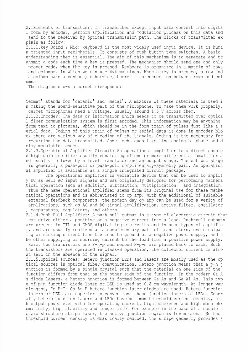
ansmit a code each time a key is pressed. The mechanism should send one and onlyproper code, when the key is pressed. Keyboard is organized in a matrix of rowsand columns. In which we can use 4x4 matrixes. When a key is pressed, a row anda column make a contact; otherwise, there is no connection between rows and columns.The diagram shows a cermet microphone:
Cermet
stands for
ceramic
and
metal
. A mixture of these materials is used in making the sound-sensitive part of the microphone. To make them work properly,cermet microphones need a voltage, usually around 1.5V across them.2.1.2.Encoder: The data or information which needs to be transmitted over optica
l fiber communication system is first encoded. This information may be anythingfrom text to pictures, which should be in the form train of pulses just like a serial data. Coding of this train of pulses or serial data is done in encoder block there are various way of encoding of the signals. Coding is the necessary forrecurring the data transmitted. Some techniques like line coding bi-phase and delay modulation codes.2.1.3.Operational Amplifier Circuit: An operational amplifier is a direct coupled high gain amplifier usually consisting of one or more differential amplifier and usually followed by a level translator and an output stage. The out put stageis generally a push-pull or push-pull complimentary-symmetry pair. An operational amplifier is available as a single integrated circuit package.
The operational amplifier is versatile device that can be used to amplify DC as well AC input signals and was originally designed for performing mathema
tical operation such as addition, subtraction, multiplication, and integration.Thus the name operational amplifier stems from its original use for these mathematical operations and is abbreviated to op-amp. With the additional of suitableexternal feedback components, the modern day op-amp can be used for a verity ofapplications, such as AC and DC signal amplification, active filter, oscillator, comparators, regulators, and others.2.1.4.Push-Pull Amplifier: A push–pull output is a type of electronic circuit thatcan drive either a positive or a negative current into a load. Push–pull outputsare present in TTL and CMOS digital logic circuits and in some types of amplifier, and are usually realized as a complementary pair of transistors, one dissipating or sinking current from the load to ground or a negative power supply, and the other supplying or sourcing current to the load from a positive power supply.Here, two transistors one P-n-p and second N-p-n are placed back to back. Boththe transistors are operated in class-B operation; the collector current is almost zero in the absence of the signal.2.1.5.Optical sources: Hetero junction LEDs and lasers are mostly used as the optical sources in optical fiber communication. Hetero junction means that a p-n junction is formed by a single crystal such that the material on one side of thejunction differs from that on the other side of the junction. In the modern Ga As diode lasers, a hetero junction is formed between Ga As and Ga Al As. This type of p-n junction diode laser or LED is used at 0.8 mm wavelength. At longer wavelengths, In P-In Ga As P hetero junction laser diodes are used. Hetero junctionlasers or LEDs are superior to conventional homo junction lasers or LEDs. Generally hetero junction lasers and LEDs have minimum threshold current density, high output power even with low operating current, high coherence and high mono chr
omaticity, high stability and longer life. For example in the case of a double hetero structure stripe laser, the active junction region is few microns. So thethreshold current density is drastically reduced. The stripe geometry provides s
8/8/2019 SAURAV RANA -FIBER OPTICS
http://slidepdf.com/reader/full/saurav-rana-fiber-optics 5/23
tability with longer lifetime for the diode. Thus it gives high power output, continuous wave operation, high efficiency, high coherence and high directionality. By means of the hetero junction formed by two different materials, both the carriers and the optical field are confined in the central active layer. The bandgap differences of adjacent layers confine the charge carriers while the step change in the indices of refraction of adjoining layers confines the optical fieldto the central active layer and provides an efficient waveguide structure. This
dual confinement leads to both high efficiency and high power output.2.2. Elements of transmission Path: In the transmission path we are used the optical fiber communication. In the optical fiber communication the signal is transfer in the form of light by obey the total internal reflection principal.2.2.1Fiber Cable: An optical fiber (or fiber) is a glass or plastic fiber that carries light along its length. Fiber optics is the overlap of applied science and engineering concerned with the design and application of optical fibers. Optical fibers are widely used in fiber-optic communications, which permits transmission over longer distances and at higher bandwidths (data rates) than other formsof communications. Fibers are used instead of metal wires because signals travel along them with less loss, and they are also immune to electromagnetic interference. Fibers are also used for illumination, and are wrapped in bundles so they
can be used to carry images, thus allowing viewing in tight spaces. Specially designed fibers are used for a variety of other applications, including sensors and lasers. Light is kept in the core of the optical fiber by total internal reflection. This causes the fiber to act as a waveguide. Fibers which support many propagation paths or transverse modes are called multi-mode fibers (MMF), while those which can only support a single mode are called single-mode fibers (SMF). Multi-mode fibers generally have a larger core diameter, and are used for short-distance communication links and for applications where high power must be transmitted. Single-mode fibers are used for most communication links longer than 550meters (1,800ft).2.2.1.Principle of operation: An optical fiber is a cylindrical dielectric waveguide (no conducting waveguide) that transmits light along its axis, by the process of total internal reflection. The fiber consists of a core surrounded by a cl
adding layer, both of which are made of dielectric materials. To confine the optical signal in the core, the refractive index of the core must be greater than that of the cladding. The boundary between the core and cladding may either be abrupt, in step-index fiber, or gradual, in graded-index fiber.2.2.2.Total internal reflection: When light traveling in a dense medium hits a boundary at a steep angle (larger than the "critical angle" for the boundary), the light will be completely reflected. This effect is used in optical fibers to confine light in the core. Light travels along the fiber bouncing back and forthoff of the boundary. Because the light must strike the boundary with an angle greater than the critical angle, only light that enters the fiber within a certainrange of angles can travel down the fiber without leaking out. This range of angles is called the acceptance cone of the fiber. The size of this acceptance cone is a function of the refractive index difference between the fiber
s core andcladding. In simpler terms, there is a maximum angle from the fiber axis at which light may enter the fiber so that it will propagate, or travel, in the core ofthe fiber. The sine of this maximum angle is the numerical aperture (NA) of thefiber. Fiber with a larger NA requires less precision to splice and work with than fiber with a smaller NA. Single-mode fiber has a small NA.2.2.3.Multi-mode fiber: Fiber with large core diameter (greater than10micrometers) may be analyzed by geometrical optics. Such fiber is called multi-mode fiber,from the electromagnetic analysis (see below). In a step-index multi-mode fiber,rays of light are guided along the fiber core by total internal reflection. Rays that meet the core-cladding boundary at a high angle (measured relative to a line normal to the boundary), greater than the critical angle for this boundary,are completely reflected. The critical angle (minimum angle for total internal r
eflection) is determined by the difference in index of refraction between the core and cladding materials. Rays that meet the boundary at a low angle are refracted from the core into the cladding, and do not convey light and hence informati
8/8/2019 SAURAV RANA -FIBER OPTICS
http://slidepdf.com/reader/full/saurav-rana-fiber-optics 6/23
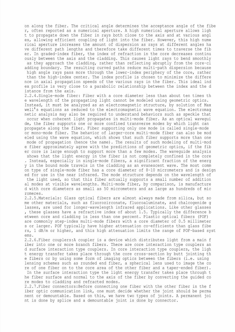
on along the fiber. The critical angle determines the acceptance angleof the fiber, often reported as a numerical aperture. A high numerical aperture allows light to propagate down the fiber in rays both close to the axis and at various angles, allowing efficient coupling of light into the fiber. However, this high numerical aperture increases the amount of dispersion as rays at different angles have different path lengths and therefore take different times to traverse the fiber. In graded-index fiber, the index of refraction in the core decreases continu
ously between the axis and the cladding. This causes light rays to bend smoothlyas they approach the cladding, rather than reflecting abruptly from the core-cladding boundary. The resulting curved paths reduce multi-path dispersion becausehigh angle rays pass more through the lower-index periphery of the core, ratherthan the high-index center. The index profile is chosen to minimize the difference in axial propagation speeds of the various rays in the fiber. This ideal index profile is very close to a parabolic relationship between the index and the distance from the axis.2.2.4.Single-mode fiber: Fiber with a core diameter less than about ten times the wavelength of the propagating light cannot be modeled using geometric optics.Instead, it must be analyzed as an electromagnetic structure, by solution of Maxwell
s equations as reduced to the electromagnetic wave equation. The electromag
netic analysis may also be required to understand behaviors such as speckle thatoccur when coherent light propagates in multi-mode fiber. As an optical waveguide, the fiber supports one or more confined transverse modes by which light canpropagate along the fiber. Fiber supporting only one mode is called single-modeor mono-mode fiber. The behavior of larger-core multi-mode fiber can also be modeled using the wave equation, which shows that such fiber supports more than onemode of propagation (hence the name). The results of such modeling of multi-mode fiber approximately agree with the predictions of geometric optics, if the fiber core is large enough to support more than a few modes. The waveguide analysisshows that the light energy in the fiber is not completely confined in the core. Instead, especially in single-mode fibers, a significant fraction of the energy in the bound mode travels in the cladding as an evanescent wave. The most common type of single-mode fiber has a core diameter of 8–10 micrometers and is design
ed for use in the near infrared. The mode structure depends on the wavelength ofthe light used, so that this fiber actually supports a small number of additional modes at visible wavelengths. Multi-mode fiber, by comparison, is manufactured with core diameters as small as 50 micrometers and as large as hundreds of micromeres.2.2.5.Materials: Glass optical fibers are almost always made from silica, but some other materials, such as fluorozirconate, fluoroaluminate, and chalcogenide glasses, are used for longer-wavelength infrared applications. Like other glasses, these glasses have a refractive index of about 1.5. Typically the difference between core and cladding is less than one percent. Plastic optical fibers (POF)are commonly step-index multi-mode fibers with a core diameter of 0.5 millimeters or larger. POF typically have higher attenuation co-efficients than glass fibers, 1dB/m or higher, and this high attenuation limits the range of POF-based systems.2.2.6.Fiber couplers:A coupler is a device which distributes light from a main fiber into one or more branch fibers. There are core interaction type couplers and surface interaction type couplers. In core interaction type couplers, the light energy transfer takes place through the core cross-section by butt jointing the fibers or by using some form of imaging optics between the fibers (i.e. usinglensing schemes such as rounded end fiber, a spherical lens used to image the core of one fiber on to the core area of the other fiber and a taper-ended fiber).In the surface interaction type the light energy transfer takes place through the fiber surface and normal to the axis of the fiber by converting the guided core modes to cladding and refracted modes.2.2.7.Fiber connectors:Before connecting one fiber with the other fiber in the f
iber optic communication link, one must decide whether the joint should be permanent or demountable. Based on this, we have two types of joints. A permanent joint is done by splice and a demountable joint is done by connector.
8/8/2019 SAURAV RANA -FIBER OPTICS
http://slidepdf.com/reader/full/saurav-rana-fiber-optics 7/23
2.2.8. Elements of Receiver: At receiver side data is received in the digital form. Then receiver performs some function like decode, amplification, demodulation. The elements of the receiver as follow:2.2.9.Optical detector: Semiconductor based photodiodes are used as optical dete
ctors in the optical fiber communication systems. They have small size, high sensitivity and fast response. There are two types of photodiodes:
(i) p-i-n photodiodes and(ii) Avalanche photodiodes (APD)
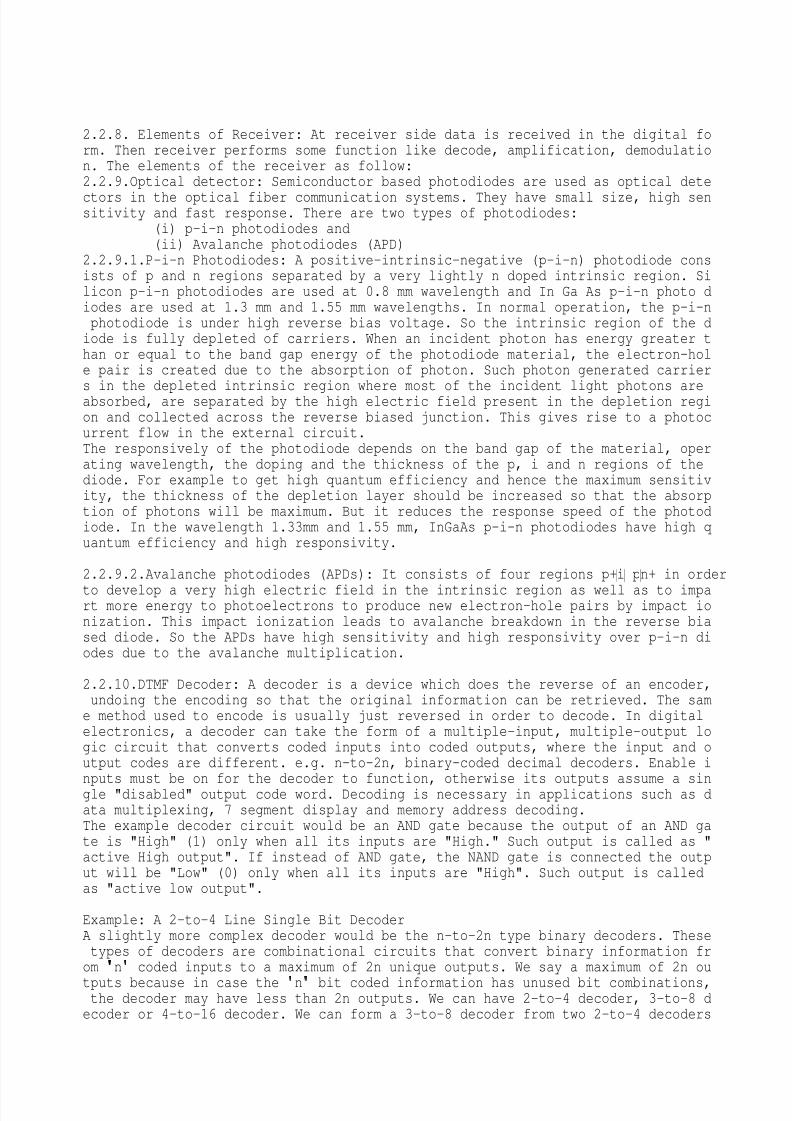
2.2.9.1.P-i-n Photodiodes: A positive-intrinsic-negative (p-i-n) photodiode consists of p and n regions separated by a very lightly n doped intrinsic region. Silicon p-i-n photodiodes are used at 0.8 mm wavelength and In Ga As p-i-n photo diodes are used at 1.3 mm and 1.55 mm wavelengths. In normal operation, the p-i-nphotodiode is under high reverse bias voltage. So the intrinsic region of the diode is fully depleted of carriers. When an incident photon has energy greater than or equal to the band gap energy of the photodiode material, the electron-hole pair is created due to the absorption of photon. Such photon generated carrier
s in the depleted intrinsic region where most of the incident light photons areabsorbed, are separated by the high electric field present in the depletion region and collected across the reverse biased junction. This gives rise to a photocurrent flow in the external circuit.The responsively of the photodiode depends on the band gap of the material, operating wavelength, the doping and the thickness of the p, i and n regions of thediode. For example to get high quantum efficiency and hence the maximum sensitivity, the thickness of the depletion layer should be increased so that the absorption of photons will be maximum. But it reduces the response speed of the photodiode. In the wavelength 1.33mm and 1.55 mm, InGaAs p-i-n photodiodes have high quantum efficiency and high responsivity.
2.2.9.2.Avalanche photodiodes (APDs): It consists of four regions p+ i p n+ in order
to develop a very high electric field in the intrinsic region as well as to impart more energy to photoelectrons to produce new electron-hole pairs by impact ionization. This impact ionization leads to avalanche breakdown in the reverse biased diode. So the APDs have high sensitivity and high responsivity over p-i-n diodes due to the avalanche multiplication.
2.2.10.DTMF Decoder: A decoder is a device which does the reverse of an encoder,undoing the encoding so that the original information can be retrieved. The same method used to encode is usually just reversed in order to decode. In digitalelectronics, a decoder can take the form of a multiple-input, multiple-output logic circuit that converts coded inputs into coded outputs, where the input and output codes are different. e.g. n-to-2n, binary-coded decimal decoders. Enable inputs must be on for the decoder to function, otherwise its outputs assume a single "disabled" output code word. Decoding is necessary in applications such as data multiplexing, 7 segment display and memory address decoding.The example decoder circuit would be an AND gate because the output of an AND gate is "High" (1) only when all its inputs are "High." Such output is called as "active High output". If instead of AND gate, the NAND gate is connected the output will be "Low" (0) only when all its inputs are "High". Such output is calledas "active low output".
Example: A 2-to-4 Line Single Bit DecoderA slightly more complex decoder would be the n-to-2n type binary decoders. Thesetypes of decoders are combinational circuits that convert binary information from
n
coded inputs to a maximum of 2n unique outputs. We say a maximum of 2n ou
tputs because in case the
n
bit coded information has unused bit combinations,the decoder may have less than 2n outputs. We can have 2-to-4 decoder, 3-to-8 decoder or 4-to-16 decoder. We can form a 3-to-8 decoder from two 2-to-4 decoders
8/8/2019 SAURAV RANA -FIBER OPTICS
http://slidepdf.com/reader/full/saurav-rana-fiber-optics 8/23
(with enable signals). Similarly, we can also form a 4-to-16 decoder by combining two 3-to-8 decoders. In this type of circuit design, the enable inputs of both 3-to-8 decoders originate from a 4th input, which acts as a selector between the two 3-to-8 decoders. This allows the 4th input to enable either the top or bottom decoder, which produces outputs of D (0) through D (7) for the first decoder, and D (8) through D (15) for the second decoder. A decoder that contains enable inputs is also known as a decoder-demultiplexer. Thus, we have a 4-to-16 deco
der produced by adding a 4th input shared among both decoders, producing 16 outputs.
2.2.11.Demultiplexer: De-multiplexers take one data input and a number of selection inputs, and they have several outputs. They forward the data input to one ofthe outputs depending on the values of the selection inputs. Demultiplexers aresometimes convenient for designing general purpose logic, because if the de-multiplexer
s input is always true, the demultiplexer acts as a decoder. This meansthat any function of the selection bits can be constructed by logically OR-ingthe correct set of outputs.2.2.12.Inverter: An inverter circuit outputs a voltage representing the oppositelogic-level to its input. Inverters can be constructed using a single NMOS tran
sistor or a single PMOS transistor coupled with a resistor. Since this
resistive-drain
approach uses only a single type of transistor, it can be fabricated atlow cost. However, because current flows through the resistor in one of the twostates, the resistive-drain configuration is disadvantaged for power consumption and processing speed. Alternately, inverters can be constructed using two complimentary transistors in a CMOS configuration. This configuration greatly reduces power consumption since one of the transistors is always off in both logic states. Processing speed can also be improved due to the relatively low resistancecompared to the NMOS-only or PMOS-only type devices. Inverters can also be constructed with Bipolar Junction Transistors (BJT) in either a resistor-transistor logic (RTL) or a transistor-transistor logic (TTL) configuration.Digital electronics circuits operate at fixed voltage levels corresponding to alogical 0 or 1 (see Binary). An inverter circuit serves as the basic logic gate
to swap between those two voltage levels. Implementation determines the actual voltage, but common levels include (0, +5V) for TTL circuits.
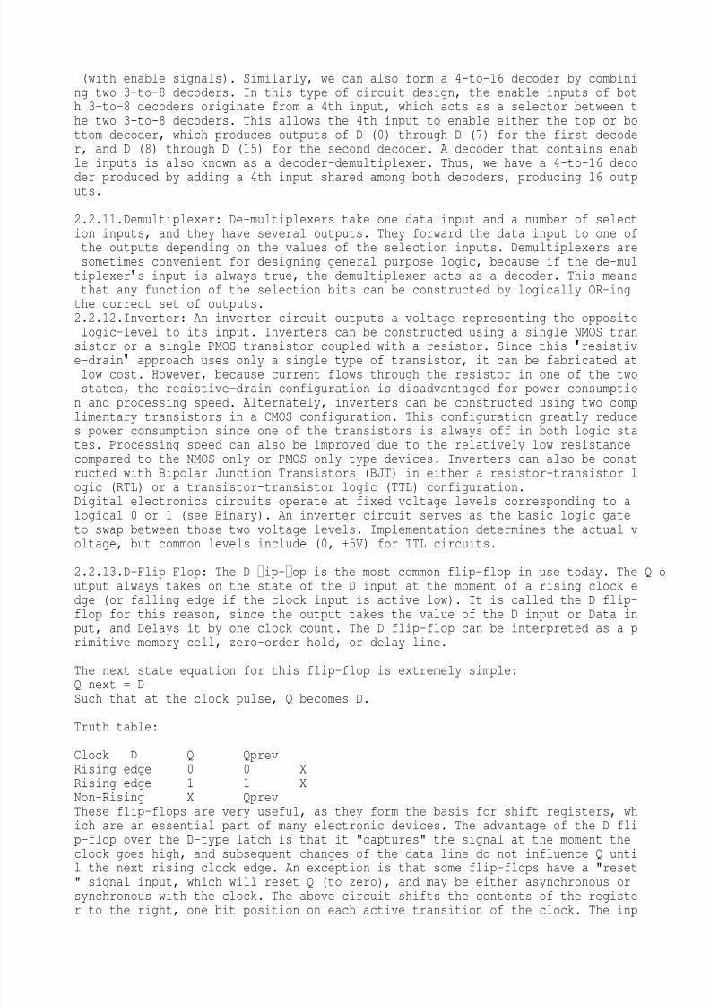
2.2.13.D-Flip Flop: The D ip-op is the most common flip-flop in use today. The Q output always takes on the state of the D input at the moment of a rising clock edge (or falling edge if the clock input is active low). It is called the D flip-flop for this reason, since the output takes the value of the D input or Data input, and Delays it by one clock count. The D flip-flop can be interpreted as a primitive memory cell, zero-order hold, or delay line.
The next state equation for this flip-flop is extremely simple:Q next = DSuch that at the clock pulse, Q becomes D.
Truth table: Clock D Q QprevRising edge 0 0 XRising edge 1 1 XNon-Rising X QprevThese flip-flops are very useful, as they form the basis for shift registers, which are an essential part of many electronic devices. The advantage of the D flip-flop over the D-type latch is that it "captures" the signal at the moment theclock goes high, and subsequent changes of the data line do not influence Q until the next rising clock edge. An exception is that some flip-flops have a "reset
" signal input, which will reset Q (to zero), and may be either asynchronous orsynchronous with the clock. The above circuit shifts the contents of the register to the right, one bit position on each active transition of the clock. The inp
8/8/2019 SAURAV RANA -FIBER OPTICS
http://slidepdf.com/reader/full/saurav-rana-fiber-optics 9/23
ut X is shifted into the leftmost bit position.
2.3.14.Seven Segment display driver: A seven-segment display (abbreviation: "7-seg(ment) display"), less commonly known as a seven-segment indicator, is a formof electronic display device for displaying decimal numerals that is an alternative to the more complex dot-matrix displays. Seven-segment displays are widely used in digital clocks, electronic meters, and other electronic devices for displ
aying numerical information. A seven segment display, as its name indicates, iscomposed of seven elements. Individually on or off, they can be combined to produce simplified representations of the Arabic numerals. Often the seven segmentsare arranged in an oblique (slanted) arrangement, which aids readability. Each of the numbers 0, 6, 7 and 9 may be represented by two or more different glyphs on seven-segment displays.The seven segments are arranged as a rectangle of two vertical segments on eachside with one horizontal segment on the top, middle, and bottom. Additionally, the seventh segment bisects the rectangle horizontally. There are also fourteen-segment displays and sixteen-segment displays (for full alphanumeric); however, these have mostly been replaced by dot-matrix displays. The segments of a 7-segment display are referred to by the letters A to G, as shown to the right, where t
he optional DP decimal point (an "eighth segment") is used for the display of non-integer numbers. The animation to the left cycles through the common glyphs ofthe ten decimal numerals and the six hexadecimal "letter digits" (A–F). It is animage sequence of a "LED" display, which is described technology-wise in the following section. Notice the variation between uppercase and lowercase letters forA–F; this is done to obtain a unique, unambiguous shape for each letter.
Chapter: 3MODULES OF THE PROJECT: There are 3 different modules of the project :Data CommunicationVoice communicationControlling Switching
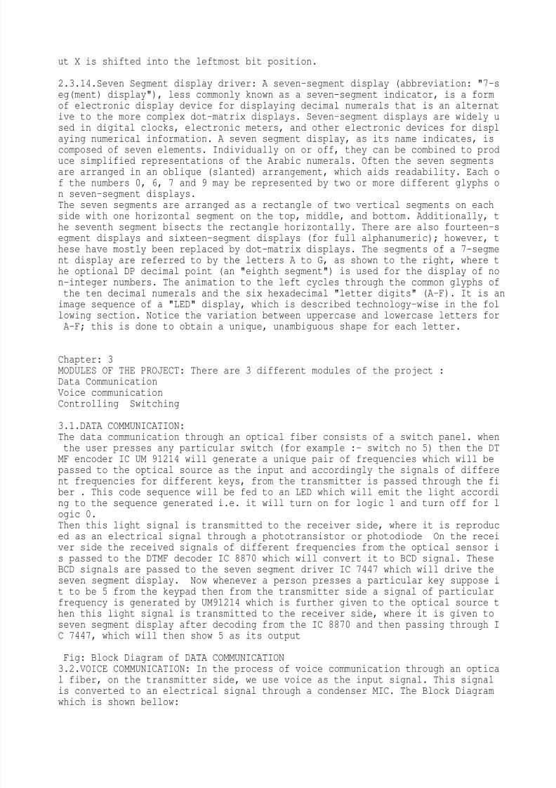
3.1.DATA COMMUNICATION:The data communication through an optical fiber consists of a switch panel. whenthe user presses any particular switch (for example :- switch no 5) then the DTMF encoder IC UM 91214 will generate a unique pair of frequencies which will bepassed to the optical source as the input and accordingly the signals of different frequencies for different keys, from the transmitter is passed through the fiber . This code sequence will be fed to an LED which will emit the light according to the sequence generated i.e. it will turn on for logic 1 and turn off for logic 0.Then this light signal is transmitted to the receiver side, where it is reproduced as an electrical signal through a phototransistor or photodiode On the receiver side the received signals of different frequencies from the optical sensor is passed to the DTMF decoder IC 8870 which will convert it to BCD signal. TheseBCD signals are passed to the seven segment driver IC 7447 which will drive theseven segment display. Now whenever a person presses a particular key suppose it to be 5 from the keypad then from the transmitter side a signal of particularfrequency is generated by UM91214 which is further given to the optical source then this light signal is transmitted to the receiver side, where it is given toseven segment display after decoding from the IC 8870 and then passing through IC 7447, which will then show 5 as its output
Fig: Block Diagram of DATA COMMUNICATION3.2.VOICE COMMUNICATION: In the process of voice communication through an optical fiber, on the transmitter side, we use voice as the input signal. This signal
is converted to an electrical signal through a condenser MIC. The Block Diagramwhich is shown bellow:
8/8/2019 SAURAV RANA -FIBER OPTICS
http://slidepdf.com/reader/full/saurav-rana-fiber-optics 10/23
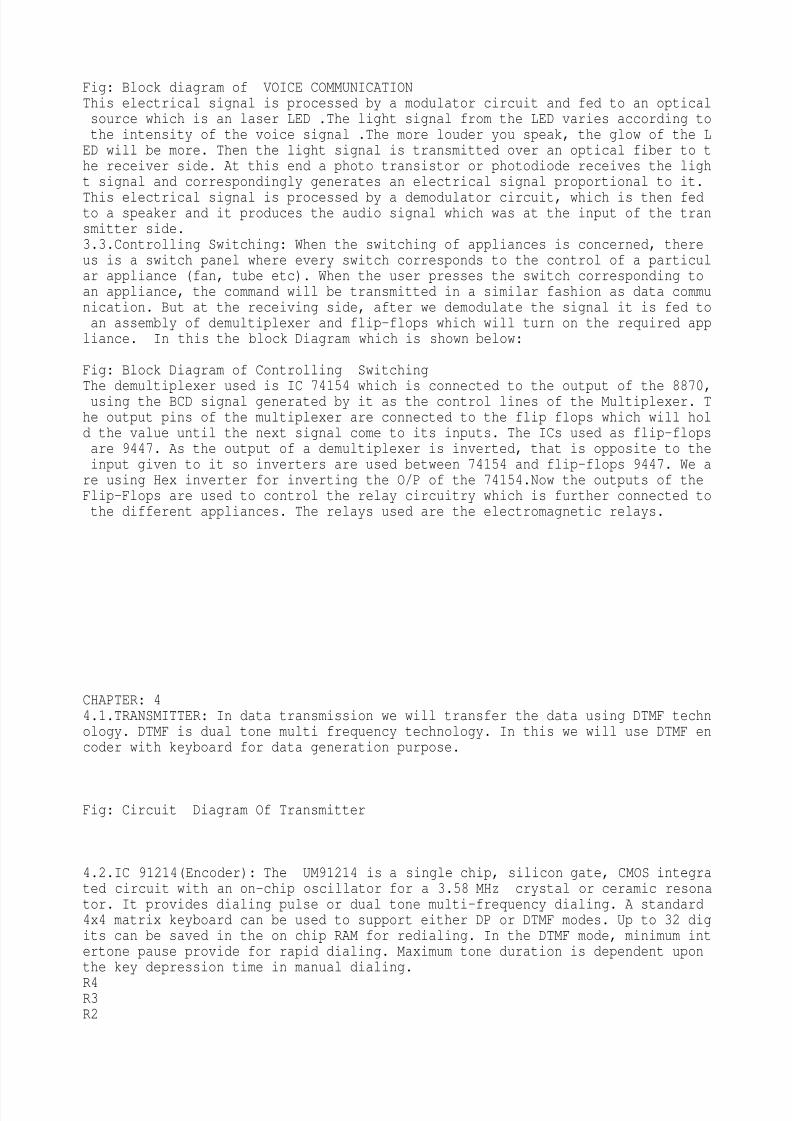
Fig: Block diagram of VOICE COMMUNICATIONThis electrical signal is processed by a modulator circuit and fed to an opticalsource which is an laser LED .The light signal from the LED varies according tothe intensity of the voice signal .The more louder you speak, the glow of the LED will be more. Then the light signal is transmitted over an optical fiber to the receiver side. At this end a photo transistor or photodiode receives the light signal and correspondingly generates an electrical signal proportional to it.
This electrical signal is processed by a demodulator circuit, which is then fedto a speaker and it produces the audio signal which was at the input of the transmitter side.3.3.Controlling Switching: When the switching of appliances is concerned, thereus is a switch panel where every switch corresponds to the control of a particular appliance (fan, tube etc). When the user presses the switch corresponding toan appliance, the command will be transmitted in a similar fashion as data communication. But at the receiving side, after we demodulate the signal it is fed toan assembly of demultiplexer and flip-flops which will turn on the required appliance. In this the block Diagram which is shown below: Fig: Block Diagram of Controlling Switching
The demultiplexer used is IC 74154 which is connected to the output of the 8870,using the BCD signal generated by it as the control lines of the Multiplexer. The output pins of the multiplexer are connected to the flip flops which will hold the value until the next signal come to its inputs. The ICs used as flip-flopsare 9447. As the output of a demultiplexer is inverted, that is opposite to theinput given to it so inverters are used between 74154 and flip-flops 9447. We are using Hex inverter for inverting the O/P of the 74154.Now the outputs of theFlip-Flops are used to control the relay circuitry which is further connected tothe different appliances. The relays used are the electromagnetic relays.
CHAPTER: 44.1.TRANSMITTER: In data transmission we will transfer the data using DTMF technology. DTMF is dual tone multi frequency technology. In this we will use DTMF encoder with keyboard for data generation purpose.
Fig: Circuit Diagram Of Transmitter
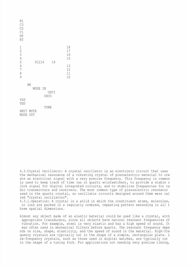
4.2.IC 91214(Encoder): The UM91214 is a single chip, silicon gate, CMOS integrated circuit with an on-chip oscillator for a 3.58 MHz crystal or ceramic resonator. It provides dialing pulse or dual tone multi-frequency dialing. A standard4x4 matrix keyboard can be used to support either DP or DTMF modes. Up to 32 digits can be saved in the on chip RAM for redialing. In the DTMF mode, minimum intertone pause provide for rapid dialing. Maximum tone duration is dependent uponthe key depression time in manual dialing.
R4R3R2
8/8/2019 SAURAV RANA -FIBER OPTICS
http://slidepdf.com/reader/full/saurav-rana-fiber-optics 11/23
R1C3C2C1DPKT
1 182 173 164 155 91214 146 137 128 119 10
HKMODE IN
OSCIOSCOVSSVDD
TONEXMIT MUTEMODE OUT
4.3.Crystal Oscillator: A crystal oscillator is an electronic circuit that usesthe mechanical resonance of a vibrating crystal of piezoelectric material to create an electrical signal with a very precise frequency. This frequency is commonly used to keep track of time (as in quartz wristwatches), to provide a stable clock signal for digital integrated circuits, and to stabilize frequencies for radio transmitters and receivers. The most common type of piezoelectric resonatorused is the quartz crystal, so oscillator circuits designed around them were called "crystal oscillators".4.3.1.Operation: A crystal is a solid in which the constituent atoms, molecules,or ions are packed in a regularly ordered, repeating pattern extending in all three spatial dimensions.
Almost any object made of an elastic material could be used like a crystal, withappropriate transducers, since all objects have natural resonant frequencies ofvibration. For example, steel is very elastic and has a high speed of sound. Itwas often used in mechanical filters before quartz. The resonant frequency depends on size, shape, elasticity, and the speed of sound in the material. High-fre
quency crystals are typically cut in the shape of a simple, rectangular plate. Low-frequency crystals, such as those used in digital watches, are typically cutin the shape of a tuning fork. For applications not needing very precise timing,
8/8/2019 SAURAV RANA -FIBER OPTICS
http://slidepdf.com/reader/full/saurav-rana-fiber-optics 12/23
a low-cost ceramic resonator is often used in place of a quartz crystal. When acrystal of quartz is properly cut and mounted, it can be made to distort in anelectric field by applying a voltage to an electrode near or on the crystal. This property is known as piezoelectricity. When the field is removed, the quartz will generate an electric field as it returns to its previous shape, and this cangenerate a voltage. The result is that a quartz crystal behaves like a circuitcomposed of an inductor, capacitor and resistor, with a precise resonant frequen
cy. Quartz has the further advantage that its elastic constants and its size change in such a way that the frequency dependence on temperature can be very low.The specific characteristics will depend on the mode of vibration and the angleat which the quartz is cut. Therefore, the resonant frequency of the plate, which depends on its size, will not change much, either. This means that a quartzclock, filter or oscillator will remain accurate. For critical applications thequartz oscillator is mounted in a temperature-controlled container, called a crystal oven, and can also be mounted on shock absorbers to prevent perturbation byexternal mechanical vibrations. Quartz timing crystals are manufactured for frequencies from a few tens of kilohertz to tens of megahertz. More than two billion (2×10⁹) crystals are manufactured annually. Most are small devices for consumerdevices such as wristwatches, clocks, radios, computers, and cell phones. Quartz
crystals are also found inside test and measurement equipment, such as counters, signal generators, and oscilloscopes.4.4.IC741 (OP-Amp): An operational amplifier, which is often called an op-amp, is a DC-coupled high-gain electronic voltage amplifier with differential inputs and, usually, a single output.. Typically the op-amp
s very large gain is controlled by negative feedback, which largely determines the magnitude of its output ("closed-loop") voltage gain in amplifier applications, or the transfer functionrequired (in analog computers). Without negative feedback, and perhaps with positive feedback for regeneration, an op-amp essentially acts as a comparator. Highinput impedance at the input terminals (ideally infinite) and low output impedance (ideally zero) are important typical characteristics Op-amps are among the most widely used electronic devices today, being used in a
vast array of consumer, industrial, and scientific devices..
4.4.1Operation: The amplifier
s differential inputs consist of a V+ input and aV-input, and ideally the op-amp amplifies only the difference in voltage between the two, which is called the differential input voltage. The output voltage ofthe op-amp is given by the equation, Where the voltage at the non-inverting terminal is, is the voltage at the inverting terminal and Gopen-loop is the open-loop gain of the amplifier. (The term open-loop refers to the absence of a feedback loop from the output to the input.) With no positive feedback, the op-amp acts as a switch. The inverting input is held at ground (0 V) by the resistor, so if the Vin applied to the non-invertinginput is positive, the output will be maximum positive, and if Vin is negative,the output will be maximum negative. Since there is no feedback from the outputto either input, this is an open loop circuit. The circuit
s gain is just the Gopen-loop of the op-amp. Adding negative feedback via Rf puts us in a different universe. Equilibrium will be established when Vout is just sufficient to reach around and pull the inverting input to the same voltage as Vin. As a simple example, if Vin = 1 V and Rf= Rg, Vout will be 2 V, the amount required to keep V– at 1 V. Because of the feedback provided by Rf, this is a closed loop circuit. Its over-all gain Vout / Vinis called the closed-loop gain Gclosed-loop. Because the feedback is negative,in this case Gclosed-loop is less than the Gopen-loop of the op-amp.
4.5.Applications:audio- and video-frequency pre-amplifiers and buffersvoltage comparators
8/8/2019 SAURAV RANA -FIBER OPTICS
http://slidepdf.com/reader/full/saurav-rana-fiber-optics 13/23
differential amplifiersdifferentiators and integratorsfiltersprecision rectifiersprecision peak detectorsvoltage and current regulatorsanalog calculators
analog-to-digital convertersdigital-to-analog convertervoltage clamps
4.6.Zener Diode: A Zener diode is a type of diode that permits current in the forward direction like a normal diode, but also in the reverse direction if the voltage is larger than the breakdown voltage known as "Zener knee voltage" or "Zener voltage".
A conventional solid-state diode will not allow significant current if it is rev
erse-biased below its reverse breakdown voltage. When the reverse bias breakdownvoltage is exceeded, a conventional diode is subject to high current due to avalanche breakdown. Unless this current is limited by external circuitry, the diode will be permanently damaged. In case of large forward bias (current in the direction of the arrow), the diode exhibits a voltage drop due to its junction built-in voltage and internal resistance. The amount of the voltage drop depends onthe semiconductor material and the doping concentrations. A Zener diode exhibits almost the same properties, except the device is specially designed so as to have a greatly reduced breakdown voltage, the so-called Zener voltage. A Zener diode contains a heavily doped p-n junction allowing electrons to tunnel from the valence band of the p-type material to the conduction bandof the n-type material. In the atomic scale, this tunnelling corresponds to thetransport of valence band electrons into the empty conduction band states; as aresult of the reduced barrier between these bands and high electric fields thatare induced due to the relatively high levels of doping on both sides. A reverse-biased Zener diode will exhibit a controlled breakdown and allow the current tokeep the voltage across the Zener diode at the Zener voltage. For example, a diode with a Zener breakdown voltage of 3.2 V will exhibit a voltage drop of 3.2 Vif reverse bias voltage applied across it is more than its Zener voltage. However, the current is not unlimited, so the Zener diode is typically used to generate a reference voltage for an amplifier stage, or as a voltage stabilizer for low-current applications.The breakdown voltage can be controlled quite accurately in the doping process.While tolerances within 0.05% are available, the most widely used tolerances are
5% and 10%.Another mechanism that produces a similar effect is the avalanche effect as in the avalanche diode. The two types of diode are in fact constructed the same way and both effects are present in diodes of this type. In silicon diod
8/8/2019 SAURAV RANA -FIBER OPTICS
http://slidepdf.com/reader/full/saurav-rana-fiber-optics 14/23
es up to about 5.6 volts, the Zener effect is the predominant effect and shows amarked negative temperature coefficient. Above 5.6 volts, the avalanche effectbecomes predominant and exhibits a positive temperature coefficient.TC depending on zener voltage In a 5.6 V diode, the two effects occur togetherand their temperature coefficients neatly cancel each other out, thus the 5.6 Vdiode is the component of choice in temperature-critical applications.Modern manufacturing techniques have produced devices with voltages lower than 5
.6 V with negligible temperature coefficients, but as higher voltage devices areencountered, the temperature coefficient rises dramatically. A 75 V diode has 10 times the coefficient of a 12 V diode.
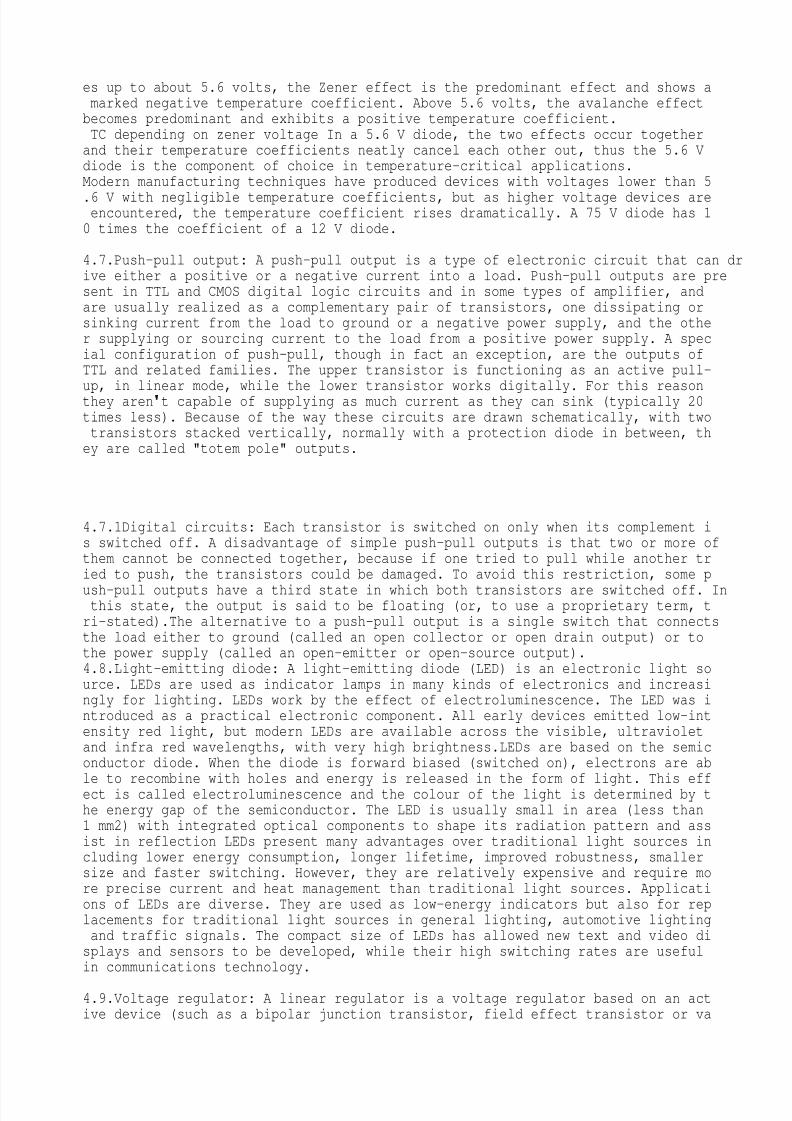
4.7.Push–pull output: A push–pull output is a type of electronic circuit that can drive either a positive or a negative current into a load. Push–pull outputs are present in TTL and CMOS digital logic circuits and in some types of amplifier, andare usually realized as a complementary pair of transistors, one dissipating orsinking current from the load to ground or a negative power supply, and the other supplying or sourcing current to the load from a positive power supply. A special configuration of push-pull, though in fact an exception, are the outputs ofTTL and related families. The upper transistor is functioning as an active pull-
up, in linear mode, while the lower transistor works digitally. For this reasonthey aren
t capable of supplying as much current as they can sink (typically 20times less). Because of the way these circuits are drawn schematically, with twotransistors stacked vertically, normally with a protection diode in between, they are called "totem pole" outputs.
4.7.1Digital circuits: Each transistor is switched on only when its complement is switched off. A disadvantage of simple push–pull outputs is that two or more ofthem cannot be connected together, because if one tried to pull while another tried to push, the transistors could be damaged. To avoid this restriction, some p
ush–pull outputs have a third state in which both transistors are switched off. Inthis state, the output is said to be floating (or, to use a proprietary term, tri-stated).The alternative to a push–pull output is a single switch that connectsthe load either to ground (called an open collector or open drain output) or tothe power supply (called an open-emitter or open-source output).4.8.Light-emitting diode: A light-emitting diode (LED) is an electronic light source. LEDs are used as indicator lamps in many kinds of electronics and increasingly for lighting. LEDs work by the effect of electroluminescence. The LED was introduced as a practical electronic component. All early devices emitted low-intensity red light, but modern LEDs are available across the visible, ultravioletand infra red wavelengths, with very high brightness.LEDs are based on the semiconductor diode. When the diode is forward biased (switched on), electrons are able to recombine with holes and energy is released in the form of light. This effect is called electroluminescence and the colour of the light is determined by the energy gap of the semiconductor. The LED is usually small in area (less than1 mm2) with integrated optical components to shape its radiation pattern and assist in reflection LEDs present many advantages over traditional light sources including lower energy consumption, longer lifetime, improved robustness, smallersize and faster switching. However, they are relatively expensive and require more precise current and heat management than traditional light sources. Applications of LEDs are diverse. They are used as low-energy indicators but also for replacements for traditional light sources in general lighting, automotive lightingand traffic signals. The compact size of LEDs has allowed new text and video displays and sensors to be developed, while their high switching rates are usefulin communications technology.
4.9.Voltage regulator: A linear regulator is a voltage regulator based on an active device (such as a bipolar junction transistor, field effect transistor or va
8/8/2019 SAURAV RANA -FIBER OPTICS
http://slidepdf.com/reader/full/saurav-rana-fiber-optics 15/23
cuum tube) operating in its "linear region" (in contrast, a switching regulatoris based on a transistor forced to act as an on/off switch) or passive devices like zener diodes operated in their breakdown region. The regulating device is made to act like a variable resistor, continuously adjusting a voltage divider network to maintain a constant output voltage. It is very inefficient compared to aswitched-mode power supply, since it regulates the voltage by burning off "unwanted" voltage as heat.
4.9.1Operation: For output voltages not provided by standard fixed regulators and load currents of less than 7 amperes, commonly-available "adjustable" three-terminal linear regulators may be used. An adjustable regulator generates a fixedlow nominal voltage between its output and its
adjust
terminal (equivalent tothe ground terminal in a fixed regulator). The "317" series (+1.25V) regulates positive voltages while the "337" series (-1.25V) regulates negative voltages. Adjustable voltage regulator circuit showing
adjust
terminal the adjustment is performed by constructing a potential divider with its ends between the regulatoroutput and ground, and its centre-tap connected to the
adjust
terminal of theregulator. The ratio of resistances determines the output voltage using the sam
e feedback mechanisms described earlier. Complex power requirements (e.g., op-amp circuits needing matched positive and negative DC supplies) are more difficult, but single IC dual tracking adjustable regulators are available
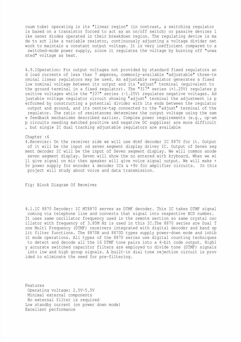
Chapter :44.Recevier: On the receiver side we will use dtmf decoder IC 8870 for it. Outputof it will be the input od seven segment display driver IC. Output of Seven segment decoder IC will be the input of Seven segment display. We will common anodeseven segment display. Seven will show the no entered with kryboard. When we will give signal on mic then speaker will give voice signal output. We will make +5v power supply for encoder & decoder ICs & +9v for amplifier circuits. In thisproject will study about voice and data transmission.
Fig: Block Diagram Of Receiver
4.1.IC 8870 Decoder: IC MT8870 serves as DTMF decoder. This IC takes DTMF signalcoming via telephone line and converts that signal into respective BCD number.It uses same oscillator frequency used in the remote section so same crystal oscillator with frequency of 3.85M Hz is used in this IC.The 8870 series are Dual Tone Multi Frequency (DTMF) receivers integrated with digital decoder and band split filter functions. The 8870B and 8870D types supply power-down mode and inhibit mode operations. All types of the 8870 series use digital counting techniquesto detect and decode all the 16 DTMF tone pairs into a 4-bit code output. Highly accurate switched capacitor filters are employed to divide tone (DTMF) signalsinto low and high group signals. A built-in dial tone rejection circuit is provided to eliminate the need for pre-filtering.
FeaturesOperating voltage: 2.5V~5.5VMinimal external components
No external filter is requiredLow standby current (on power down mode)Excellent performance
8/8/2019 SAURAV RANA -FIBER OPTICS
http://slidepdf.com/reader/full/saurav-rana-fiber-optics 16/23
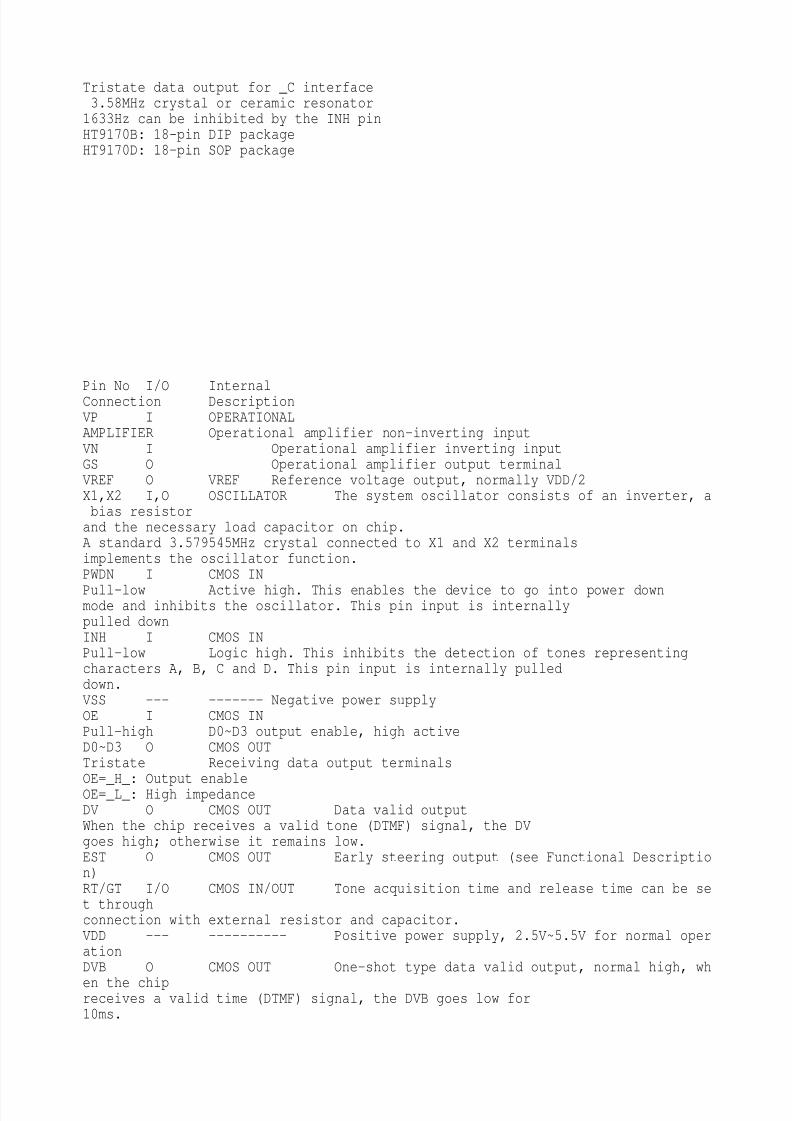
Tristate data output for _C interface3.58MHz crystal or ceramic resonator1633Hz can be inhibited by the INH pinHT9170B: 18-pin DIP packageHT9170D: 18-pin SOP package
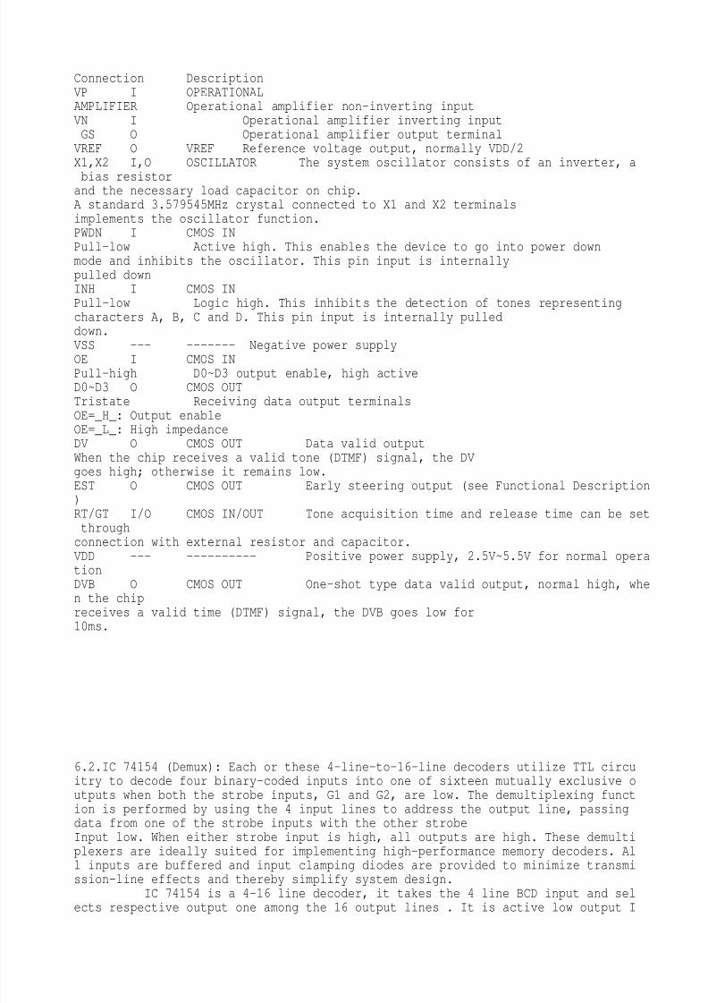
Pin No I/O InternalConnection DescriptionVP I OPERATIONALAMPLIFIER Operational amplifier non-inverting inputVN I Operational amplifier inverting inputGS O Operational amplifier output terminalVREF O VREF Reference voltage output, normally VDD/2X1,X2 I,O OSCILLATOR The system oscillator consists of an inverter, abias resistorand the necessary load capacitor on chip.A standard 3.579545MHz crystal connected to X1 and X2 terminalsimplements the oscillator function.PWDN I CMOS IN
Pull-low Active high. This enables the device to go into power downmode and inhibits the oscillator. This pin input is internallypulled downINH I CMOS INPull-low Logic high. This inhibits the detection of tones representingcharacters A, B, C and D. This pin input is internally pulleddown.VSS --- ------- Negative power supplyOE I CMOS INPull-high D0~D3 output enable, high activeD0~D3 O CMOS OUTTristate Receiving data output terminalsOE=_H_: Output enableOE=_L_: High impedanceDV O CMOS OUT Data valid outputWhen the chip receives a valid tone (DTMF) signal, the DVgoes high; otherwise it remains low.EST O CMOS OUT Early steering output (see Functional Description)RT/GT I/O CMOS IN/OUT Tone acquisition time and release time can be set throughconnection with external resistor and capacitor.VDD --- ---------- Positive power supply, 2.5V~5.5V for normal operationDVB O CMOS OUT One-shot type data valid output, normal high, wh
en the chipreceives a valid time (DTMF) signal, the DVB goes low for10ms.
8/8/2019 SAURAV RANA -FIBER OPTICS
http://slidepdf.com/reader/full/saurav-rana-fiber-optics 17/23
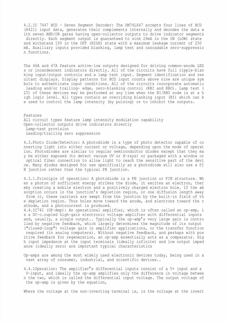
4.2.IC 7447 BCD - Seven Segment Decoder: The DM74LS47 accepts four lines of BCD(8421) input data, generates their complements internally and decodes the data with seven AND/OR gates having open-collector outputs to drive indicator segmentsdirectly. Each segment output is guaranteed to sink 24mA in the ON (LOW) stateand withstand 15V in the OFF (HIGH) state with a maximum leakage current of 250mA. Auxiliary inputs provided blanking, lamp test and cascadable zero-suppression functions.
The 46A and 47A feature active-low outputs designed for driving common-anode LEDs or incandescent indicators directly. All of the circuits have full ripple-blanking input/output controls and a lamp test input. Segment identification and resultant displays. Display patterns for BCD input counts above nine are unique symbols to authenticate input conditions. All of the circuits incorporate automaticleading and/or trailing- edge, zero-blanking control (RBI and RBO). Lamp test (LT) of these devices may be performed at any time when the BI/RBO node is at a high logic level. All types contain an overriding blanking input (BI) which can be used to control the lamp intensity (by pulsing) or to inhibit the outputs.
FeaturesAll circuit types feature lamp intensity modulation capabilityOpen-collector outputs drive indicators directlyLamp-test provisionLeading/trailing zero suppression
4.3.Photo Diode/Detector: A photodiode is a type of photo detector capable of converting light into either current or voltage, depending upon the mode of operation. Photodiodes are similar to regular semiconductor diodes except that they may be either exposed (to detect vacuum UV or X-rays) or packaged with a window oroptical fiber connection to allow light to reach the sensitive part of the device. Many diodes designed for use specifically as a photodiode will also use a PI
N junction rather than the typical PN junction. 4.3.1.Principle of operation: A photodiode is a PN junction or PIN structure. When a photon of sufficient energy strikes the diode, it excites an electron, thereby creating a mobile electron and a positively charged electron hole. If the absorption occurs in the junction
s depletion region, or one diffusion length awayfrom it, these carriers are swept from the junction by the built-in field of the depletion region. Thus holes move toward the anode, and electrons toward the cathode, and a photocurrent is produced.4.4.IC741 (OP-Amp): An operational amplifier, which is often called an op-amp, is a DC-c.oupled high-gain electronic voltage amplifier with differential inputsand, usually, a single output.. Typically the op-amp
s very large gain is controlled by negative feedback, which largely determines the magnitude of its output("closed-loop") voltage gain in amplifier applications, or the transfer functionrequired (in analog computers). Without negative feedback, and perhaps with positive feedback for regeneration, an op-amp essentially acts as a comparator. High input impedance at the input terminals (ideally infinite) and low output impedance (ideally zero) are important typical characteristics Op-amps are among the most widely used electronic devices today, being used in avast array of consumer, industrial, and scientific devices..
4.4.1Operation: The amplifier
s differential inputs consist of a V+ input and aV-input, and ideally the op-amp amplifies only the difference in voltage between the two, which is called the differential input voltage. The output voltage of
the op-amp is given by the equation, Where the voltage at the non-inverting terminal is, is the voltage at the invert
8/8/2019 SAURAV RANA -FIBER OPTICS
http://slidepdf.com/reader/full/saurav-rana-fiber-optics 18/23
ing terminal and Gopen-loop is the open-loop gain of the amplifier. (The term open-loop refers to the absence of a feedback loop from the output to the input.) With no positive feedback, the op-amp acts as a switch. The inverting input is held at ground (0 V) by the resistor, so if the Vin applied to the non-invertinginput is positive, the output will be maximum positive, and if Vin is negative,the output will be maximum negative. Since there is no feedback from the output
to either input, this is an open loop circuit. The circuit
s gain is just the Gopen-loop of the op-amp. Adding negative feedback via Rf puts us in a different universe. Equilibrium will be established when Vout is just sufficient to reach around and pull the inverting input to the same voltage as Vin. As a simple example, if Vin = 1 V and Rf= Rg, Vout will be 2 V, the amount required to keep V– at 1 V. Because of the feedback provided by Rf, this is a closed loop circuit. Its over-all gain Vout / Vinis called the closed-loop gain Gclosed-loop. Because the feedback is negative,in this case Gclosed-loop is less than the Gopen-loop of the op-amp.
4.5.Push–pull output: A push–pull output is a type of electronic circuit that can dr
ive either a positive or a negative current into a load. Push–pull outputs are present in TTL and CMOS digital logic circuits and in some types of amplifier, andare usually realized as a complementary pair of transistors, one dissipating orsinking current from the load to ground or a negative power supply, and the other supplying or sourcing current to the load from a positive power supply. A special configuration of push-pull, though in fact an exception, is the outputs of TTL and related families. The upper transistor is functioning as an active pull-up, in linear mode, while the lower transistor works digitally. For this reason they aren
t capable of supplying as much current as they can sink (typically 20 times less). Because of the way these circuits are drawn schematically, with twotransistors stacked vertically, normally with a protection diode in between, they are called "totem pole" outputs.
4.5.1.Digital circuits: Each transistor is switched on only when its complementis switched off. A disadvantage of simple push–pull outputs is that two or more ofthem cannot be connected together, because if one tried to pull while another tried to push, the transistors could be damaged. To avoid this restriction, somepush–pull outputs have a third state in which both transistors are switched off. In this state, the output is said to be floating (or, to use a proprietary term,tri-stated).The alternative to a push–pull output is a single switch that connectsthe load either to ground (called an open collector or open drain output) or tothe power supply (called an open-emitter or open-source output).
4.6.Seven-segment display: A seven-segment display (abbreviation: "7-seg(ment) display"), less commonly known as a seven-segment indicator, is a form of electronic display device for displaying decimal numerals that is an alternative to themore complex dot-matrix displays. Seven-segment displays are widely used in digital clocks, electronic meters, and other electronic devices for displaying numerical information.4.6.1.Concept and visual structure: A seven segment display, as its name indicates, is composed of seven elements. Individually on or off, they can be combinedto produce simplified representations of the Arabic numerals. Often the seven segments are arranged in an oblique (slanted) arrangement, which aids readability.Each of the numbers 0, 6, 7 and 9 may be represented by two or more different glyphs on seven-segment displays.
The seven segments are arranged as a rectangle of two vertical segments on each
side with one horizontal segment on the top, middle, and bottom. Additionally, the seventh segment bisects the rectangle horizontally.The segments of a 7-segment display are referred to by the letters A to G, as sh
8/8/2019 SAURAV RANA -FIBER OPTICS
http://slidepdf.com/reader/full/saurav-rana-fiber-optics 19/23
own to the right, where the optional DP decimal point (an "eighth segment") is used for the display of non-integer numbers. Seven segments are, effectively, thefewest required to represent each of the ten Hindu-Arabic numerals with a distinct and recognizable glyph. Bloggers have experimented with six-segment and evenfive-segment displays with such novel shapes as curves, angular blocks and serifs for segments; however, these often require complicated and/or non-uniform shapes and sometimes create unrecognizable glyphs.
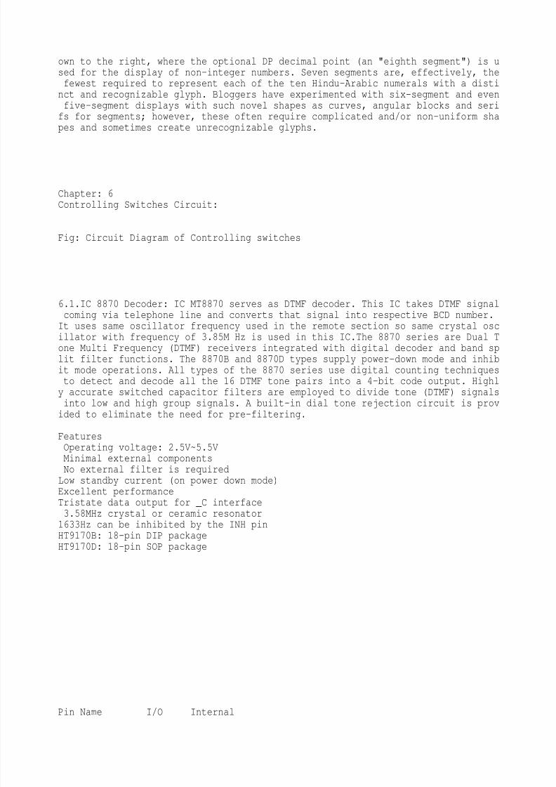
Chapter: 6Controlling Switches Circuit:
Fig: Circuit Diagram of Controlling switches
6.1.IC 8870 Decoder: IC MT8870 serves as DTMF decoder. This IC takes DTMF signalcoming via telephone line and converts that signal into respective BCD number.It uses same oscillator frequency used in the remote section so same crystal oscillator with frequency of 3.85M Hz is used in this IC.The 8870 series are Dual Tone Multi Frequency (DTMF) receivers integrated with digital decoder and band split filter functions. The 8870B and 8870D types supply power-down mode and inhibit mode operations. All types of the 8870 series use digital counting techniquesto detect and decode all the 16 DTMF tone pairs into a 4-bit code output. Highly accurate switched capacitor filters are employed to divide tone (DTMF) signalsinto low and high group signals. A built-in dial tone rejection circuit is prov
ided to eliminate the need for pre-filtering. FeaturesOperating voltage: 2.5V~5.5VMinimal external componentsNo external filter is requiredLow standby current (on power down mode)Excellent performanceTristate data output for _C interface3.58MHz crystal or ceramic resonator1633Hz can be inhibited by the INH pinHT9170B: 18-pin DIP packageHT9170D: 18-pin SOP package
Pin Name I/O Internal
8/8/2019 SAURAV RANA -FIBER OPTICS
http://slidepdf.com/reader/full/saurav-rana-fiber-optics 20/23
8/8/2019 SAURAV RANA -FIBER OPTICS
http://slidepdf.com/reader/full/saurav-rana-fiber-optics 21/23
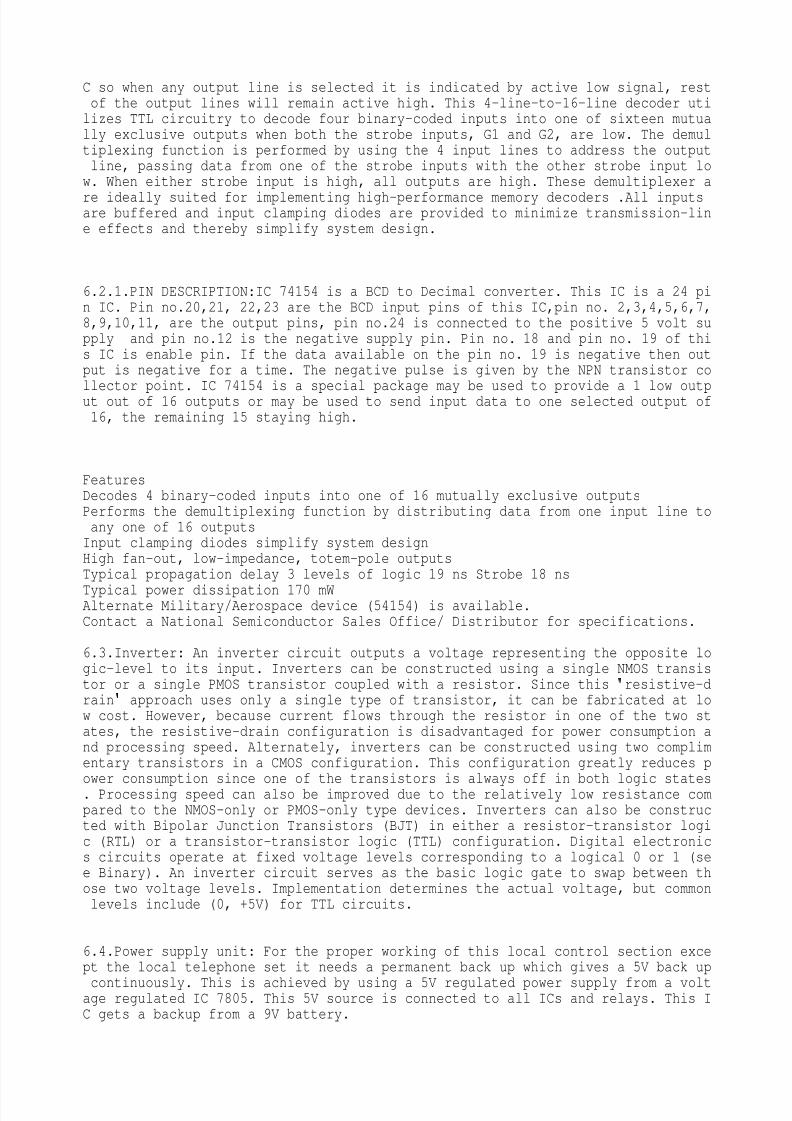
C so when any output line is selected it is indicated by active low signal, restof the output lines will remain active high. This 4-line-to-16-line decoder utilizes TTL circuitry to decode four binary-coded inputs into one of sixteen mutually exclusive outputs when both the strobe inputs, G1 and G2, are low. The demultiplexing function is performed by using the 4 input lines to address the outputline, passing data from one of the strobe inputs with the other strobe input low. When either strobe input is high, all outputs are high. These demultiplexer a
re ideally suited for implementing high-performance memory decoders .All inputsare buffered and input clamping diodes are provided to minimize transmission-line effects and thereby simplify system design.
6.2.1.PIN DESCRIPTION:IC 74154 is a BCD to Decimal converter. This IC is a 24 pin IC. Pin no.20,21, 22,23 are the BCD input pins of this IC,pin no. 2,3,4,5,6,7,8,9,10,11, are the output pins, pin no.24 is connected to the positive 5 volt supply and pin no.12 is the negative supply pin. Pin no. 18 and pin no. 19 of this IC is enable pin. If the data available on the pin no. 19 is negative then output is negative for a time. The negative pulse is given by the NPN transistor co
llector point. IC 74154 is a special package may be used to provide a 1 low output out of 16 outputs or may be used to send input data to one selected output of16, the remaining 15 staying high.
FeaturesDecodes 4 binary-coded inputs into one of 16 mutually exclusive outputsPerforms the demultiplexing function by distributing data from one input line toany one of 16 outputsInput clamping diodes simplify system designHigh fan-out, low-impedance, totem-pole outputsTypical propagation delay 3 levels of logic 19 ns Strobe 18 ns
Typical power dissipation 170 mWAlternate Military/Aerospace device (54154) is available.Contact a National Semiconductor Sales Office/ Distributor for specifications.
6.3.Inverter: An inverter circuit outputs a voltage representing the opposite logic-level to its input. Inverters can be constructed using a single NMOS transistor or a single PMOS transistor coupled with a resistor. Since this
resistive-drain
approach uses only a single type of transistor, it can be fabricated at low cost. However, because current flows through the resistor in one of the two states, the resistive-drain configuration is disadvantaged for power consumption and processing speed. Alternately, inverters can be constructed using two complimentary transistors in a CMOS configuration. This configuration greatly reduces power consumption since one of the transistors is always off in both logic states. Processing speed can also be improved due to the relatively low resistance compared to the NMOS-only or PMOS-only type devices. Inverters can also be constructed with Bipolar Junction Transistors (BJT) in either a resistor-transistor logic (RTL) or a transistor-transistor logic (TTL) configuration. Digital electronics circuits operate at fixed voltage levels corresponding to a logical 0 or 1 (see Binary). An inverter circuit serves as the basic logic gate to swap between those two voltage levels. Implementation determines the actual voltage, but commonlevels include (0, +5V) for TTL circuits.
6.4.Power supply unit: For the proper working of this local control section except the local telephone set it needs a permanent back up which gives a 5V back up
continuously. This is achieved by using a 5V regulated power supply from a voltage regulated IC 7805. This 5V source is connected to all ICs and relays. This IC gets a backup from a 9V battery.
8/8/2019 SAURAV RANA -FIBER OPTICS
http://slidepdf.com/reader/full/saurav-rana-fiber-optics 22/23
6.5.Relay driver circuit: To carry out the switching of any appliances or devices we commonly use the relays. Since the output of the D flip flop is normally +5V or it is the voltage of logic high state. So we cannot use this output to runthe device or appliances. Therefore here we use relays which can handle a high v
oltage of 230V or more, and a high current in the rate of 10Amps to energize theelectromagnetic coil of the relays +5V is sufficient. Here we use the transistors to energize the relay coil. The output of the D flip-flop is applied to the base of the transistor T5 – T15 via a resister. When the base voltage of the transistor is above 0.7V the emitter-base (EB) junction of the transistor forward biased as a result transistor goes to saturation region it is nothing but the switching ON the transistor. This intern switches on the relay. By this the device isswitches ON. When the output of D flip-flop goes low the base voltage drops below 0.7V as a result the device also switches OFF.
Chapter :7PROCREDURE TO MAKE PROJECT:-7.1.IDEA OF PROJECT:In this stage student select the topic of the project ofthe project. It’s the main stage of project work.its the area where talented students shows their innovative ideas. Innovative students make project with a new idea then others. We selected this project because we want to do something in with our own hands. We use main electronics components uded in the industry. Firstof all we selected the GSM based project. Then we drop idea because there was little bit practical electronics to learn and mobile companies already providingthose facility.7.2.TESTING OF MAIN CIRCUIT- Then we collect the components of project. It wasnot a easy task. Because no shop in our area have all the components. Then aftercollection of components we test the circuit on bread board - step by step. Bec
ause we want to sure about the circuit. We checked it in different steps beacuuse it was a big project and was not possible to check it in a single step.7.3COMPONENT MOUNTING- We kept the hole size from 0.8mm yo 1 mm for leads of components. Then we insert components according ton their pitches.7.4 SODERING- Afgter mounting components we solder the components ane by one. Wekept the temperature of iron at 250 degree to 400 degree. Because above this temperature it can damage to component. We used general iron available in the market of siron company. Its temperature was nearly 350 degree acc to company specifications. We used soldering wire of 22 gauge with flux inbuilt.7.5FINAL TESTING- After that we test the circuit step by step . and insert theICs after testing the one portion of the circuit an then after other step by step. Its was tough work we tested voltage across the compents with erepect to ground. And current in series.

8/8/2019 SAURAV RANA -FIBER OPTICS
http://slidepdf.com/reader/full/saurav-rana-fiber-optics 23/23
BIBLIOGRAPHY
www.omron.comwww.electronicsforu.comwww.datasheets.comwww.howstuffworks.comwww.sciencefair.comwww.technologiestoday.comwww.google.com“Voice and Data” magazine“Science Biz” magazine“Semiconductors” magazine“Fiber Optic Communication Systems” by GovindP. Aggarwal
“Linear Integrated Circuits” by Gayakwad“Electronics Devices And Circuits” by Salivahanan“Digital Circuits” by Mauresmano