situational method engineering applied to business modelling
TRANSCRIPT

Situational Method Engineering applied to Business
Modelling
José Filipe Meira Semedo
Dissertação para obtenção do Grau de Mestre em
Engenharia Informática e Computadores
Júri
Presidente: Luís Eduardo Teixeira Rodrigues
Orientador: Professor Doutor Artur Miguel Pereira Alves Caetano
Vogal: Professor Doutor André Ferreira Ferrão Couto e Vasconcelos
Novembro de 2011


i
Agradecimentos
Em primeira instância agradeço ao Professor Artur Caetano pela orientação disponibilizada ao longo
deste trabalho.
Agradeço,
Aos meus pais por todo o apoio que me deram e a pela paciência que demonstraram para
com a minha pessoa.
Ao meu irmão Paulo, como uma referência e fonte de inspiração.
À tia Inácia pelo seu apoio incondicional.
À Diana, quem admiro, pelo seu apoio, paciência, esforço e dedicação.
A todos os meus amigos pela amizade e momentos que temos experienciado, em especial
ao Tiago, ao Nuno, ao David, ao Daniel, ao Xico, à Juliana, à Ana Sofia, ao Jónatas e ao
Paulo.
Aos meus sobrinhos Anaís e Lucas.
Ao Professor Marchueta, por todos os ensinamentos e por me ter ajudo nas decisões
tomadas, que deram início ao meu percurso académico.
Por fim, à tia Celeste, eterna gratidão.

ii

iii
Abstract
The business modelling of an enterprise involves multiple business stakeholders and their respective
concerns. To model all the concepts addressed to an organisation‘s business we use Business
Process Modelling Languages in order to obtain different views over the same Business Process
Diagram, or the same Enterprise Architecture Diagram. The views are obtained from viewpoints
based on the stakeholders’ concerns. In this project we aim to use the Situational Method Engineering
to conceptualize a library with chunks of viewpoints, representing steps of methods to obtain views
over business process diagrams on a multi-stakeholder perspective.
Keywords: Situation, Viewpoint, View, Representation, Multi-stakeholder, Concern, Business
Process Modelling

iv

v
Resumo
A modelação do negócio de uma organização envolve múltiplos interessados, stakeholders, bem
como os seus interesses e preocupações. Para modelar todos os conceitos adjacentes ao negócio
usamos linguagens de modelação (BPML) de modo a obter diferentes vistas sobre o mesmo
diagrama de processos de negócio ou de arquitectura empresarial. As vistas são obtidas a partir de
pontos de vista baseados nos supramencionados interesses dos stakeholders. Neste projecto iremos
usar o Situational Method Engineering para conceptualizar uma biblioteca de fragmentos com
pedaços de pontos de vista, representando métodos para obter vistas sobre diagramas de processos
de negócio, numa abordagem multi-stakeholder.
Palavras-chave: Situação, Ponto de Vista, Vista, Representação, Multi-stakeholder, Interesse,
Modelação de Processos de Negócio

vi

vii
“When it is obvious that the goals cannot
be reached, don't adjust the goals, adjust the
action steps.”
Confucius

viii

ix
Contents
1 Introduction ______________________________________________________________ 1
1.1 Work Objectives __________________________________________________________ 2
1.1.1 Clarification of the Problem 2
1.1.2 Objectives 2
2 Related Work_____________________________________________________________ 4
2.1 Situational Method Engineering ______________________________________________ 4
2.1.1 Method Chunks Repository 5
2.1.2 Method Chunk 5
2.1.3 Reuse Frame 6
2.1.4 Method Chunks Classification 7
2.1.5 Assembly-Based Method Construction 7
2.2 Enterprise Engineering ____________________________________________________ 10
2.3 Enterprise Ontology ______________________________________________________ 11
2.4 Enterprise Architecture ____________________________________________________ 12
2.5 ArchiMate ______________________________________________________________ 14
2.6 IEEE 1471, Viewpoints and Views ___________________________________________ 15
2.6.1 A Framework for Classifying Viewpoints 17
2.7 Business Process Modelling Languages ______________________________________ 18
2.7.1 Business Process Modeling Notation 20
2.7.2 Business Process Generic Metamodel 21
2.8 Discussion ______________________________________________________________ 22
3 Method Proposal _________________________________________________________ 23
3.1 Method One – Chunks Creation and Managing Reuse Frame ______________________ 24
3.2 Method Two – Situation Assembly ___________________________________________ 24
4 Method Usage ___________________________________________________________ 26
4.1 Situation One - Break Points Identification _____________________________________ 26
4.2 Situation Two – Critical Points Identification ____________________________________ 29
4.3 Situation One and Situation Two - Activity Flow _________________________________ 33
5 Applications _____________________________________________________________ 35
5.1 Situation One - Actor Cooperation Viewpoint ___________________________________ 35
5.2 Situation Two - Context Diagram Viewpoint ____________________________________ 37
5.3 Situation One and Situation Two - Activity Flow _________________________________ 39
6 Conclusions _____________________________________________________________ 40
6.1 Validation _______________________________________________________________ 40
6.2 Contributions ____________________________________________________________ 41
6.3 Future Work _____________________________________________________________ 41
7 References _____________________________________________________________ 42
x
List of Figures
Figure 1: Assembly-based approach for SME ................................................................................. 5
Figure 2: Method Chunk metamodel ............................................................................................... 6
Figure 3: Requirements Map example for a new method ................................................................ 8
Figure 4: Enterprise Engineering and Organisational Sciences .................................................... 11
Figure 5: Systems Engineering Process ........................................................................................ 11
Figure 6: Enterprise Architecture Layers ....................................................................................... 13
Figure 7: ArchiMate main concepts ............................................................................................... 15
Figure 8: ArchiMate domains ......................................................................................................... 15
Figure 9: Conceptual model of architecture description ................................................................ 16
Figure 10: Classification framework for viewpoints........................................................................ 17
Figure 11: BPMN diagram example ............................................................................................... 21
Figure 12: Business Process Generic Metamodel......................................................................... 22
Figure 13: Situation chunk ............................................................................................................. 23
Figure 14: Proposed Method One ................................................................................................. 24
Figure 15: Situation Assembling Method ....................................................................................... 25
Figure 16: Break Points Algorithm ................................................................................................. 27
Figure 17: Break Points Algorithm execution example .................................................................. 28
Figure 18: Situation Chunks example from S1 .............................................................................. 28
Figure 19: Critical Points Algorithm execution example ................................................................ 31
Figure 20: Chunk representing the algorithm to decompose activities in order to identify break or
critical points ......................................................................................................................................... 33
Figure 21: Situation One and Situation Two - Activity Flow ........................................................... 34
Figure 22: Model for actor cooperation viewpoint .......................................................................... 36
Figure 23: Actor Cooperation View ................................................................................................ 36
Figure 24: Context Diagram ........................................................................................................... 38
Figure 25: Chunk representing the algorithm to decompose activities in order to identify relations
between actors and the organization environment. .............................................................................. 38
Figure 26: Situation One and Situation Two - Activity Flow ........................................................... 39

xi
List of Tables
Table 1: Reuse Frame example .................................................................................................... 23
Table 2: Situation Assembly Method ............................................................................................. 24
Table 3: Reuse Frame filled - Situation 1 ...................................................................................... 29
Table 4: Critical Points Algorithm ................................................................................................... 30
Table 5: Break and Critical Points Algorithm ................................................................................. 32
Table 6: Reuse Frame filled - Situation 1 and 2 ............................................................................ 33
Table 7: Reuse Frame filled with Situation 1 – Actor Cooperation Viewpoint ............................... 37
Table 8: Reuse Frame filled - Situation 1 and 2 of Applications Chapter ...................................... 39

xii
Acronyms
BP Business Process
BPD Business Process Diagram
BPML Business Process Modelling Language
BPMN Business Process Modelling Notation
EA Enterprise Architecture
ISD Information System Development
OU Organizational Unit
SME Situational Method Engineering

1
1 Introduction
The scope of this work is situated on the business modelling of an enterprise, involving their
stakeholders, respective concerns and views. There isn’t a unique view for all the business
stakeholders; over the same model we can represent different views. Using the Situational Method
Engineering applied to Business Process Modelling we aim to represent those views.
We are experiencing a transition today: while in the past we had Information Systems
Engineering, nowadays we have Enterprise Engineering, supporting that IT is not a black box to the
organisations anymore. A methodology to support and fulfil the purposes of Enterprise Engineering is
Enterprise Architecture, which provides support to organisational change when business
requirements that come from the respective stakeholders and Information Technology requirements
are met. Enterprise Architecture aligns Business with IT [1].
On Enterprise Architecture we can differentiate three layers main: Business, Application and
Technology. Our work is focused on the Business layer, in how we model the business itself. At the
operational level, business modelling is commonly referred as Business Process Modelling. There are
many Business Process Modelling Languages (BPML) and different techniques that are used to
model and represent business processes, identifying who executes the business processes (actors)
and what’s the actors’ behaviour (roles). BPML help us to understand how business activities operate
and how they are aligned with the organisation, supporting the business [2].
An Enterprise Architecture of a System is described by an Enterprise Description. That
description has models and identifies multiples Stakeholders – System Stakeholders. Each
stakeholder has their concern or concerns leading to a set of Viewpoints, represented by Views.
Therefore an Enterprise Description is organised and described by a set of Views of System models.
Taking those concepts to the Business layer of the Enterprise Architecture, we will face multiples
stakeholders and their respective concerns which lead to a set of visualizations over one Business
Process Model (BPM) or multiple ones. We call the set of visualizations or representations as views.
The engineering of information systems development is different in each situation. Information
Systems Development (ISD) depends of different organisational, technical and human factors, so the
complexity of each varies. Therefore, there is no universal and unique method to perform information
systems engineering, we need to use, adapt and configure specific methods and tools for each
situation. In this perspective we have the Situational Method Engineering (SME), which is a
methodology that focuses on the creation of the specific methods on the fly according to the ISD
situation, instead of looking for universally applicable ones. There are some approaches of SME but
most of them promote de construction and adaptation of new methods by assembling reusable
method fragments or method chunks stored in a method repository - assembly-based. The methods
constructed will be modular, thanks to the interconnection between the fragments. That modularity
leads to more flexible and adaptable methods.
Through the next sections, this thesis will address subjects related with SME and Business
Process Modelling, their issues and utilities, helping us to achieve the desired solution. Due to the

2
nature of this work we will formally define the problem, our objectives, as well as the contributions that
we are aiming to achieve this work goals.
Work Objectives 1.1
This section contextualizes and clarifies our problem as well as the objectives of our research work.
Will be enounced some questions and hypotheses to answer them, which help us to decompose the
problem at hand in sub-problems, to a better fulfilment of our objectives.
1.1.1 Clarification of the Problem
To apply Business Process Modelling there are different BPML’s and techniques used to model and
represent business processes as well as the elements addressed to them. Using BMPML’s we will
lead to multiples models and representations over the business context – Business Process Diagrams
(BPD) is an example. Over that BPD’s the stakeholders will have their concerns accomplished
representing the desired views.
In the context of Business Process Modelling we can lead to a set of different BPD’s and
different views over that, according to the business stakeholders’ concerns. Those views are obtained
from viewpoints, but we don’t know how to construct viewpoints, knowing their constituents only.
The SME is a methodology that focuses on the creation of the specific methods on the fly
according to the ISD situation instead of looking for universally applicable ones. Therefore using the
SME to construct methods to obtain views over BPD’s, we may reach a manner to create views in a
consistent way.
In the addressed context, the thesis main question is:
Is the SME a mechanism that allows us to generate views over the same Business Process Model in
a consistent way?
1.1.2 Objectives
The Situational Method Engineering is used to build new methods according to a situation,
decomposing existing methods into chunks, storing them into a chunk repository or library and
selecting the appropriate ones to build the desired method. Our work objectives is to prove that we
can use the SME and all the concepts addressed to it to build a chunk library with chunks of
viewpoints and use it to represent the stakeholders’ concerns, in a multi-stakeholder perspective. We
are aiming also to prove that the library is extensible and adaptable.

3
With this work we reach the following addressed questions and their hypothesis:
Q1: Is it possible to specify a view based in a well-defined method?
H1: We can create methods to obtain views, trough the decomposition of viewpoints using chunks.
Q1/H1 Using chunks to specify views turns possible creating consistent views. A chunk is defined in
SME as a constituent block of a method. If we can create views based in a method we obtain
consistent views.
Q2: Can we construct a library with viewpoint chunks?
H2: The library can be constructed using the chunks created in H1 to populate the library.
Q2/H2 The library makes reuse possible; serves as a repository for chunks; can be incrementally
created; is a key artefact in SME.
Q3: Is it possible to apply refactoring over a library of viewpoint chunks?
H3: Use the chunks of H2 modifying them to reuse in the maximum number of viewpoints -
situations.
Q3/H3 Refining chunks we reduce granularity; more granular chunks leads to more reuse.
4
2 Related Work
After contextualizing and defining the objectives of this project, this section enunciates the
background of our project, establishing the concepts and areas of interest. Will be addressed the
Situational Method Engineering, the domains of Business Process Modelling, Enterprise Architecture
and Viewpoints specification.
Situational Method Engineering 2.1
The engineering of information systems development is different in each situation. Information
Systems Development (ISD) depends of different organisational, technical and human factors, so the
complexity of each varies. To achieve this, there are numerous methods for ISD. Such methods
typically consist of descriptions of the activities to be performed, the products to be delivered, and the
tools to be used. Commercial methods, being released by software houses and consultancy firms, are
usually made up of several volumes that lead to entire book shelves. Methods can be considered as a
standardization of the Information Systems Engineering process, in order to enable the efficient and
effective performance of that process. A problem with these methods is that they hardly take into
account the situation in which an information system is developed. Therefore there is no universal and
unique method to perform that engineering, we need to use, adapt and configure specific methods
and tools for each situation. The multi-purpose methods contain a set of activities and constructs but
they don’t provide guidance to how adapt them to fit the specific characteristics and the context of an
Information System. [4, 5, 8].
To solve that issue the discipline of Situational Method Engineering (SME) focuses on the
creation of the specific methods on the fly, instead of looking for a universally applicable ones [4].
Taking into account the project context and type, SME aims the process of designing, constructing
and adapting methods for the development of Information Systems [6].
There are some approaches of SME but most of them promote de construction and
adaptation of new methods by assembling reusable method fragments or method chunks stored in a
method repository - assembly-based [4,7]. The methods constructed will be modular, thanks to the
interconnection between the fragments. That modularity leads to more flexible and adaptable
methods.
On the other hand we have another approach called method configuration that aims for
organisations to choose a commercial system development methodology and adapt it to the
situational factors of the project. But once again we face the problem of method adaptability and
flexibility [4].
Taking the assembly-based approach for SME, as we can see on Figure 1 [4], we will have
two core components: Methods Chunks Repository and Reuse Frame. And we have here the concept
of Method Chunk. In the next sections will be explained what they are and what’s them purpose.

5
Figure 1: Assembly-based approach for SME
2.1.1 Method Chunks Repository
One of the core elements in the SME framework is the Method Chunks Repository. The role of this
repository is to store reusable parts of methods as prospective method building blocks. Those
reusable parts are called Method Chunks [4].
2.1.2 Method Chunk
A method is not considered a monolithic block; it consists of fragments set also called chunks. Those
chunks have different granularity and they can describe the product, i.e. which is created as well as
the process aspect, i.e. how is created. The fragments can comprise a single method activity or
construct, but they can also represent a single method [5].
A method chunk is a reusable building block to a method construction or adaptation, as the
situation requires. Supporting what was said before, a chunk has a Product Part and a Process Part,
analogously a method is considered as a couple of two interrelated models: Product Model and
Process Model. The two parts of the chunk structurally related make the Chunk’s Body. Besides the
Body, a chunk has an Interface and a Descriptor, as we can see on Figure 2 [4].

6
Figure 2: Method Chunk metamodel
A method chunk ensures the coupling of a process part and its related product part. The Product Part,
also called product fragment, represents the product to be delivered by the method chunk. The
Process Part, also called process fragment, offers guidelines, allowing produce the product. For
example, in the construction of a use case model, the Process Part of the method chunk provides
guidelines for the use case model construction. Whereas the Process Part provides the definitions of
concepts as actor, use case, scenario, used in the model.
The Interface of the method chunk captures the reuse context that the method chunk applies.
It is formalized by a couple <situation, intention>.The Situation characterizes the situation that is the
input of the chunk. The Intention represents the goal that the chunk achieves.
The Descriptor associated to every method chunk extends the contextual view captured in the
chunk Interface. It defines in more detail the reuse context of the chunk. The Descriptor takes values
from the Reuse Frame and associates them to the corresponding method chunk [4].
2.1.3 Reuse Frame
In the field of method engineering some efforts have been made to provide efficient classification and
retrieving techniques to store and retrieve method chunks. Classification and retrieving techniques are
currently based on structural relationships of the chunks (specialization, composition, alternative, etc)
and reuse intention matching.
The ISD methods are always adapted; steps are added, removed or skipped. Different factors
related to the project; the technology, the team expertise and the business domain, lead to this
tailoring. A reuse frame aggregates different ISD critical aspects useful to tailor ISD methods, taking
into account organisational, technical and human dimensions [4, 9]. It allows to better qualify method
chunks when we put them into the repository and to enable more powerful matching techniques to
choose them when looking at similar ISD methodological problems. It also allows better expressing
methodological needs for a specific ISD project, improving the chance to get adequate and useful
method chunks.
In the Reuse Frame all the critical knowledge about ISD is represented in a tree. Leafs are
aspects and intermediary nodes are families. The nodes close to the root node represent general
aspects whereas the nodes close to leaf nodes represent precise aspects [4].

7
2.1.4 Method Chunks Classification
The method chunks can be classified by the granularity layer which is the most discriminative of four
dimensions - perspective, abstraction, level and layer of granularity. That layer can be compared with
a decomposition level of a method. A method, from the process perspective, usually consists of
stages, which are decomposed into activities and individual steps that are planned in the terms of its
means and purposes [7, 10].
A method chunk can be in one of five possible granularity layers [7]:
Method, Addresses the complete method for the developing of the information system;
Stage, Addresses a segment of the life-cycle of the information system;
Model, Addresses a perspective of the information system. That perspective is a system
aspect of an abstraction level;
Diagram, Addresses the representation of a view over a Model layer method chunk;
Concept, Addresses the concepts and associations of the method chunks as well as the
manipulations defined on them.
2.1.5 Assembly-Based Method Construction
According to Gupta and Prakash, the method engineering is characterized by three main phases:
method requirements specification, method design and method construction and implementation. This
work approach for assembly-based method construction follows the same pattern.
The approach for Assembly-Based method construction aims to building a method on the fly
in order to match as well as possible the situation of the project at hand. It consists in selecting
reusable method components, called method chunks, according to the current project requirements,
from the method chunks repository and assembling them [4].This approach is requirements-driven, it
means that the method engineering must start by definition of requirements for the method. The
method chunks matching these requirements can be retrieved from the method chunks repository.
Finally, the selected chunks are assembled in order to compose a new method or to enhance an
existing one [4, 8].
For the Assembly-Based approach we differentiate three main steps:
I. Method Requirements Specification;
II. Method Chunks Selection;
III. Method Chunks Assembly.

8
I. Method Requirements Specification
The requirements specification helps establishing guidelines to define the requirements for the
project-specific method in terms of required Information System development activities, by
specifying the type of these activities and the order of their execution. Examples of those activities
can be goal-driven requirements elicitation, scenario-based requirements specification,
conceptual schema definition and interface modelling. We use the reuse frame in order to
characterize the project situation and to select the predefined activities.
To enhance an existing method there we can differentiate three types of method adaptation:
The method in use can be strong in terms of its product model but weak with respect to
its process model, which will be the subject of adaptation and enhancement. Alternative
ways of working will be added in the method;
The adaptation can be to simply add a new functionality to the existing method;
The project at hand could not need some functionality offered by the method.
In all these cases, the requirements definition process is driven by the identification of the
method engineering intentions, the three adaptation cases can be combined in the selected
method adaptation. In the case of a brand new method construction the requirements
specification is not only to produce the list of method engineering intentions allowing to adapt the
selected method, but to identify the full set of engineering intentions that would be reached by the
new method [4, 11].
The requirements specification to build a new method lead to a set of requirements
expressed as a map (i.e. strategic guideline) that is called the Requirements Map, Figure 3.
Figure 3: Requirements Map example for a new method

9
The method engineer has to construct a new method, supporting:
The definition of functional system requirements, goal-driven or actor-driven based;
Their conceptualization by using linguistic devices such as scenarios or use cases;
Their validation in an animated fashion as prototyping and other simulation
mechanisms.
The map captures three core requirements intentions, infer a requirement, conceptualize a
requirement and validate a requirement [4, 11].
II. Method Chunks Selection
After the method requirements have been specified, we can start the selection of the method
chunks matching the requirements. Therefore the selection process is based on the requirements
map and the objective in this step is to select method chunks. Each selected chunk can satisfy a
part of the requirements, covering at least one strategy of the requirements map, or even satisfy
all the requirements and cover the whole requirements map.
Will be performed chunk selection queries, specifying the reuse intention of the method
chunk and giving values to different reuse context criteria specified in the chunk descriptor. It is
also possible to refine the chunk selection query by modifying selection parameters. The situation
and intention defined in the chunk interface can also be useful during the chunk selection
process.
Each retrieved chunk is validated by evaluating its degree of matching to the
requirements. This is done by applying similarity measures between the Requirements Model and
the Process Model of the selected chunk. It provides guidelines for functional system
requirements elicitation in the form of goal hierarchies and requirements conceptualization in the
form of scenarios. The actor-driven strategy for requirements elicitation can be covered by a
method chunk extracted from the Use Case model, which recommends identifying the actors of
the system under consideration and the role they have to play with the system in order to discover
the required use cases.
The chunk selection process provides different guidelines which allow refining the
candidate chunk by analysing in more detail if it matches the requirements. The requirements
map also proposes to look for an aggregate chunk of the candidate that might provide a solution
for the missing requirements [4, 11].
III. Method Chunks Assembly
When at least two chunks have been selected, the method engineer can progress in the
assembly of these chunks. There are two core types of assembly guidelines in the assembly
process, Assembly by Association and Assembly by Integration.
The Assembly by Association is relevant when the method chunks to assemble
correspond to two different system engineering functionalities, therefore they allow to achieve
different engineering intentions and the output of one chunk is used as the input of the second

10
one. Such method chunks generally do not have common elements in their product and process
models and the assembly process is therefore deal mostly with making the bridge between the
two chunks. More precisely, the product models of the chunks must be connected by their
different concepts and the connection between their process models would be defined by an
execution order.
The Assembly by Integration is relevant to assemble chunks that have similar engineering
goals but provide different ways to satisfy it. In such a case, the process and product models are
overlapping - They contain some identical or similar elements. The assembly process consists in
identifying the common elements in the chunks product and process models and merging them
[4].
Enterprise Engineering 2.2
The traditional organisational sciences give short help to enterprises in how to implement strategies
effectively in a controlled way [15]. The vast majority of strategic initiatives fail, meaning that
enterprises are unable to gain success from their strategy [16]. Enterprises need to be more agile,
more adaptive, and more transparent. The problems faced by the enterprises are traditionally
addressed with black box thinking based knowledge, i.e., knowledge concerning the function and the
behaviour of enterprises. That knowledge is definitely sufficient to manage an enterprise in a range of
control. However, it is totally inadequate to meet performance goals that are outside that range, we
are talking about changing an enterprise. In order to take care about those changes in a systematic
and controlled way, we need white box based knowledge, i.e., knowledge that concerns about the
construction and the operation of enterprises. Therefore we need a paradigm shift for developing and
applying that knowledge in what we thinking about enterprises, since the traditional organisational
sciences are not able to ensure that enterprises are wholly coherently and consistently integrated.
The needed new point of view is that enterprises are designed, engineered and implemented systems
with a well defined purpose [15, 16].
The key that enables technology for shaping future enterprises is the modern information and
communication technology, but there is an emerged perception of the information systems sciences,
that the core notion for deep understanding the relationship between organisation, information and
communication technology is the agreements and commitments between persons. In 1970’s the
content of communication was the main concern, now the intention of communication is put on top of
its content. It explains and clarifies the organisational notions of collaboration and cooperation, as well
as authority and responsibility. It also situates organisations in the category of social systems instead
of information systems. Therefore we have the transition from the era of Information Systems
Engineering to the era of Enterprise Engineering, while at the same time we merge it with relevant
parts of the Organisational Sciences, as we can see in Figure 4 [1] we have Enterprise Engineering
as an emerging discipline that studies enterprises from an engineering perspective and its basic
paradigm is that enterprises are well designed and implemented social systems, which can be
redesigned and reimplemented in the case of a change is needed. The purpose of Enterprise
Engineering discipline is to combine relevant parts from organisational sciences and the information

11
systems sciences, and to create theories and methodologies for the analysis, design, redesign, and
implementation of future enterprises. To fulfil that purpose have already emerged two methodologies:
Enterprise Ontology and Enterprise Architecture [1, 16].
Figure 4: Enterprise Engineering and Organisational Sciences
Enterprise Ontology 2.3
Enterprise Ontology is a methodology that allows understanding the enterprise construction and
operation in an independent manner of its implementation. Enterprise Ontology applied on a system is
called System Ontology, we can assume a parallelism.
On the one hand System Ontology generically represents the highest-level of the
constructional model of a system, only shows essential system features fully independent of its
implementation. On the other hand we have the implementation model, the lowest-level, which allows
a system’s full implementation, based in an available technological platform.
The model produced by System Ontology is called ontological model, it significantly reduces
the complexity when compared with the implementation model. Therefore, applying the notion of
Enterprise Ontology we can made intellectual manageable changes on an enterprise [1, 16]. The
presented model on Figure 5 [1] supports what was said before, it represents a system engineering
process.
Figure 5: Systems Engineering Process
12
Enterprise Architecture 2.4
To build the architecture we will face complex challenging tasks because of the diverse dependencies
within an organisation. We can find dependencies between various domains, like strategy, products
and services, business processes, organisational structure, applications, information management
and technical infrastructure. We need to have a good definition of these different domains and their
interrelationships, so together they form the enterprise architecture of an organisation [20].
Defining Enterprise Architecture, it is a methodology that establishes the design restrictions of
a building strategy. Generically it is a consistent and coherent aggregation of principles that guides
the design, redesign, the implementation and reimplementation of a specific change project [16].
Therefore EA express the components and its relationships of an organisation, providing systematic
support to organisational change when requirements of the business stakeholders and IT are met.
The IT artefacts found on EA will be IT platforms, software components, applications, etc. While
business artefacts will be organisational goals, products, services, business processes, etc. [17, 18]
Designing the architecture involves the transformation of requirements into a high-level
blueprint of the system to be designed and involves fundamental design decisions which have impact
on the entire design process [18]. With an EA purposefully designed and well defined, an organisation
will certainly ensure its consistency, agility and efficiency.
An EA model represents the enterprise’s as-is and the to-be architecture, an EA framework
provides [17]:
One or more metamodels of EA description;
One or more methods for design and evolution;
An unique vocabulary for EA;
A set of reference models that can be used as standards and templates for EA design and
evolution.
For the AE representation there are frameworks and they distinguish some layers, most of them
differentiate the layers expressed on Figure 6.

13
Figure 6: Enterprise Architecture Layers
A layered architecture framework is useful in order to represent different aspects in different models,
as long as overall consistency is preserved by appropriately modelling the metamodel of frameworks.
A brief description of the architecture layers addressed above is [17, 19]:
The Business Architecture represents the fundaments of an enterprise from a business
strategy viewpoint. Some typical artefacts represented on this layer are value networks,
relationships to customer and supplier processes, targeted market segments, offered
services, organisational goals, and strategic projects;
The Process Architecture represents the fundaments of organisation service development,
service creation, and service distribution in the relevant enterprise context. Some typical
artefacts represented on this layer are business processes, organisational units,
responsibilities, performance indicators, and informational flows;
The Integration Architecture represents the fundaments of organisation information system
components in the relevant enterprise context. Design and evolution principles for this layer
focus on agility, cost efficiency, integration and speed. Some typical artefacts represented on
this layer are enterprise services, application clusters, integration systems and data flows;
The Software Architecture represents the fundaments of organisation software artefacts,
like software services and data structures. This layer has an available vast range of design
and evolution principles of computer science;
Business Architecture
Process Architecture
Integration Architecture
Software Architecture
Infrastruture Architecture

14
The Technology or Infrastructure Architecture represents the fundaments of organisation
computing telecommunications hardware and networks. This layer has also an available vast
range of design and evolution principles of computer science.
ArchiMate 2.5
ArchiMate is an enterprise modelling language that was developed in Netherlands by the cooperation
between several Dutch partners with the purpose of providing an integrated view of the different
domains inside an organization [16]. ArchiMate offers a common language for describing the
construction and operation of business processes, organisational structures, information flows, IT
systems and technical infrastructure [22]. Therefore the ArchiMate language defines the relationships
between the concepts in different architectures. Concepts in the ArchiMate language cover the
business, application, and technology layers of an enterprise. So, we differentiate three viewpoints
over the Enterprise Architecture [21].
The three ArchiMate layers addressed above are described as [22]:
The Business layer addresses products and services offered by the organisation to its
external customers, realized by business processes which are executed by business actors or
roles;
The Application layer provides support for the business layer by application services which
are realized by application components;
The Technology layer represents a set of infrastructural services realized, e. g. by hardware
infrastructure and networking services, needed to run applications from the layer above.
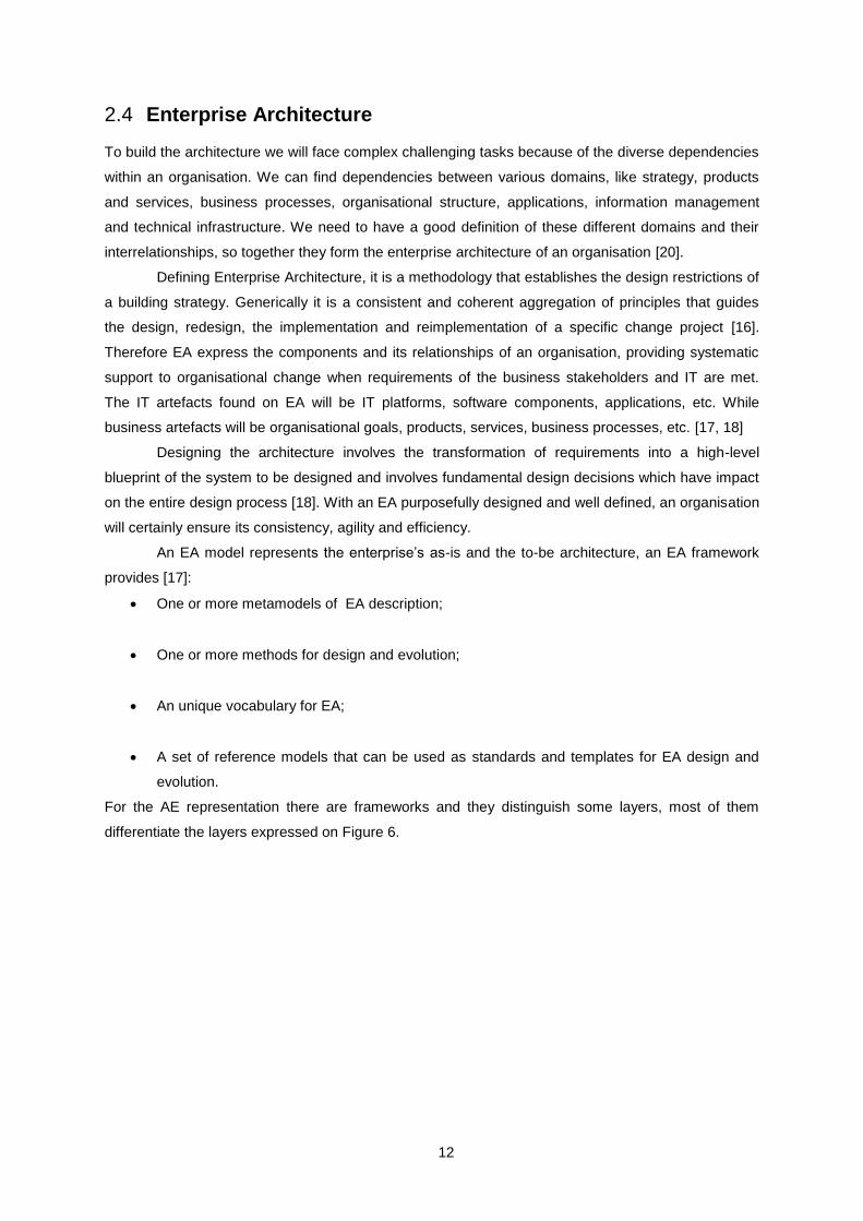
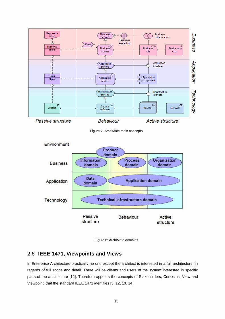
From the ArchiMate main concepts and domains expressed on Figure 7 and Figure 8 we
distinguish the Behavioural concepts that are assigned to Active structural ones, showing who or what
performs behaviour. In the example, the elements role, interface and collaboration are assigned to
business process, service and interaction, respectively. Moreover we also recognise Passive
structural elements, i.e., the objects on which behaviour is performed [22].
15
Figure 7: ArchiMate main concepts
Figure 8: ArchiMate domains
IEEE 1471, Viewpoints and Views 2.6
In Enterprise Architecture practically no one except the architect is interested in a full architecture, in
regards of full scope and detail. There will be clients and users of the system interested in specific
parts of the architecture [12]. Therefore appears the concepts of Stakeholders, Concerns, View and
Viewpoint, that the standard IEEE 1471 identifies [3, 12, 13, 14]:
16
Stakeholders: Are the persons who have interests in an architectural part of a system. They
can be a single person, a group or an organisation, as users, acquirers, developers, and
maintainers of the system;
Concerns: Are the interests of the stakeholders. Therefore, concerns are simply things the
stakeholders care about the system, pertaining to the system’s operations, its development or
other context aspects;
View: Is a representation of the system from the perspective of its related concerns;
Viewpoint: Specifies the conventions to construct and use a view. A viewpoint point is a
pattern or a template to develop a view, establishing the view’s audience and purposes.
A view will lead to a model or a set of models of the system’s architecture and if a stakeholder
requires information from aspects in different layers of the architecture, it will be integrated. A model
makes possible creating powerful techniques for visualisation and analysis of enterprise architectures.
[12]
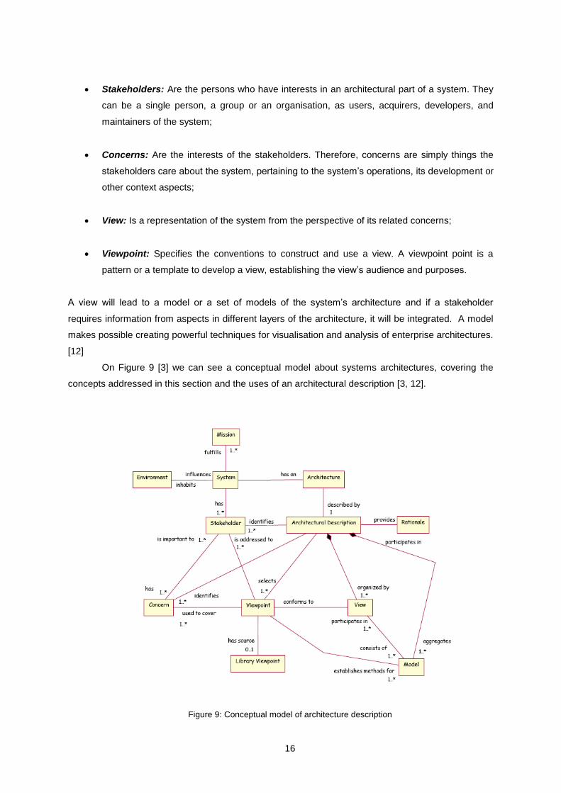
On Figure 9 [3] we can see a conceptual model about systems architectures, covering the
concepts addressed in this section and the uses of an architectural description [3, 12].
Figure 9: Conceptual model of architecture description
17
Supporting the mentioned before, a viewpoint is a template to develop individual views,
establishing the purposes, the audience and the techniques for its creation and analysis.
In order to satisfy the IEEE 1471 standard a viewpoint should specify at least:
A viewpoint name;
The stakeholders that the viewpoint is aimed at;
The concerns the viewpoint addresses;
The language, modelling techniques, or analytical methods that can be used in construct a
view;
2.6.1 A Framework for Classifying Viewpoints
In order to support architects and other stakeholders in the selection of the appropriate viewpoints
from a viewpoint library, the viewpoints can be classified according to their purpose and content. The
proposed classification may be applied to any existing set of viewpoints or it can be used to identify
new ones to be defined. The scheme below can be used to categorise and understand viewpoints
based on the stakeholders objectives and concerns.
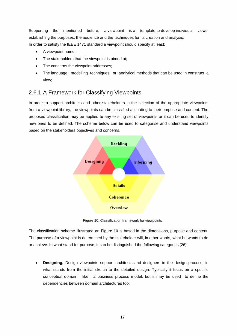
Figure 10: Classification framework for viewpoints
The classification scheme illustrated on Figure 10 is based in the dimensions, purpose and content.
The purpose of a viewpoint is determined by the stakeholder will, in other words, what he wants to do
or achieve. In what stand for purpose, it can be distinguished the following categories [26]:
Designing, Design viewpoints support architects and designers in the design process, in
what stands from the initial sketch to the detailed design. Typically it focus on a specific
conceptual domain, like, a business process model, but it may be used to define the
dependencies between domain architectures too;

18
Deciding, These viewpoints assist managers in the decision making process, offering
insight into multi-domain architecture relations. As Deciding Viewpoints examples we have
cross-reference tables, lists and reports.
Informing, These viewpoints help to inform any stakeholder about the enterprise
architecture, in order to achieve understanding, obtain commitment and convince
adversaries. Typical examples of these viewpoints are illustrations, animations, cartoons, and
flyers.
Details, Viewpoints at this level typically consider one layer and one aspect from the
ArchiMate framework expressed on Figure 8.Typical examples are business process models.
This level is relevant to stakeholders concerned with design or operations, such process
owners, responsible for the effective and efficient execution of a business process.
Coherence, At this level, either multiple layers are spanned or multiple aspects. Extending
the view to more than one layer or aspects, the viewpoint user will be enabled to focus
on architectural relationships, e.g., process-uses-system (multiple layer) or application-
uses-object (multiple aspect). Typical stakeholders of these viewpoints are operational
managers, responsible for a collection of IT services or business processes.
Overview, Viewpoints at this level address both multiple layers and multiple aspects. Such
overviews are typically addressed to enterprise architects.
Business Process Modelling Languages 2.7
The definition of Business Process according to Davenport (1993) is [23]:
A process is simply a structured set of activities designed to produce a specified output for a particular
customer or market. It implies a strong emphasis on how work is done within an organisation, in
contrast to a product's focus on what. A process is thus a specific ordering of work activities across
time and place, with a beginning, an end, and clearly identified inputs and outputs: a structure for
action. Therefore, in the business context, a process represents the activities set that an organisation
needs to operate in order to accomplish the needs of an internal or external customer, so we can
create value to the costumer. In order to achieve business goals, an activity represents the manner
how the organisational entities need to collaborate [24].
Taking into account the business layer and some elements addressed to it, Business
Processes, Actors and Roles:
A business actor is an organisational entity capable of performing behaviour. It’s the entity
who executes the business process(es);

19
A business role represents a specific behaviour of a business actor participating in a specific
context.
Moreover we can differentiate Business Activities as the smallest level of decomposition of
business behaviour and Business services that are coherent pieces used to expose business
functionality to the environment [22].
To model business there are Business Process Modelling Languages (BPML) and techniques
that help us to understand how business activities operate and how they are aligned with the
organisation, supporting the business [24]. That will be addressed in the next sections, as well as a
BPML categorization and a generic metamodel for BPML evaluation.
In the context of BPML and techniques we can categorize them into six classes according
their focus and viewpoints of business. However this classes or categories may overlap in some
manner. The classes are: transformation-based, conversation-based, goal-based, actor-based,
object-oriented and systematic approaches. Described as [24]:
Transformation-based: Languages that focus on the description of how activities transform
the resources, transforming inputs in outputs. This is represented by control flow or data flow
mechanisms. As examples of this approach we have BPMN and IDEF- languages;
Conversation-based: Languages that focus on the actors’ interactions and collaborations to
achieve some task. The collaborations are represented as transactions. Therefore we have a
business process decomposed as a set of collaborations between actors. Examples of this
approach are DEMO, BAT and Action Workflow;
Goal-based: Also called constrain-based. Languages that establish the boundaries to
perform a process. In this approach, activities are defined as means to achieve business
goals, following rules. Therefore, we can decompose a business process into goals and rules;
Actor-based: Also called role-based. Languages that focus on the actors’ behaviour in a
process. Specifying what are the actors’ roles and collaborations. In this approach a business
process is seen as a set of roles and its respective activities. Examples of this approach are
RAD and STRIM;
Object-oriented: Languages that model activities as objects, classified in classes. This
approach uses concepts of object-oriented design, as encapsulation and polymorphism. We
have a business process decomposed as a set of objects that represent activities. UML is
used as the standard language to this approach;
Systematic Approaches: Describe business processes as a set of emergent relationships
between systems. That set represent the business activities.

20
2.7.1 Business Process Modeling Notation
As an example addressed to the classification of BPML’s, we have BPMN (Business Process
Modelling Notation) as a transformation-based BPML, which provides flow descriptions of business
process easy to read and understand by all business users. BPMN defines a Business Process
Diagram (BPD), which is based on a Flow Chart technique, designed to create graphical models of
business processes [1, 2]. A flow chart is a formalization of a logic sequence.
The main characteristic of this technique is its flexibility and it is important because a process
can be described in different ways [3].
In BPMN we can find the following elements [4]:
Flow Objects: Represent the core elements. Can be activities, events and Gateways.
o Activity: Represented by a rounded-corner rectangle. It is a generic term for work that
represents a task or a sub-process;
o Event: Represented by a circle and is something that happens during the course of a
business process. Is used as the process trigger and the result;
o Gateway: Represented by a diamond shape. Is used to control the sequence flow –
divergence and convergence. A gateway determines a decision.
Connecting Objects: Used to connect the flow objects, creating the structure of the process.
Can be Message Flow, Sequence Flow and Association.
o Message Flow: Show the order of activities;
o Sequence Flow: Show the flow of messages between two separate process
participants;
o Association: Used to associate text, data or other artefacts to flow objects.
Swimlanes: Used as a mechanism to organise activities into separate visual categories, so
we can illustrate different functional capabilities or responsibilities. Can be a pool or a lane.
o Pool: Represents a participant in a process;
o Lane: Represents a sub-partition within a pool. Are used to categorize and organise
activities.
Artefacts: Used to extend the basic notation and modelling specific contexts. Can be Data
Object, Group or Annotation.
o Data Object: Used to show how data is required or produced by activities;
o Group: Is used to analysis purposes. Do not affect the sequence flow;
o Annotation: Used to modeller to provide additional information about the BMPN
diagram.
We can take as examples of BPMN diagram the model expressed on Figure 11[4].

21
Figure 11: BPMN diagram example
2.7.2 Business Process Generic Metamodel
In addition to the BPML’s classification we propose a generic metamodel from business process
theory [25] (Figure 12) to evaluate BPML’s. This metamodel was previously used in works in the
context of Business Process Modelling [1, 2].
The generic metamodel is used to:
Identify strengths and limitations of BPML’s;
Turn easier the selection of a BPML depending on the purpose;
Cover the basic concepts and relationships of the business process;
Make a comparison between BPML’s, illustrating their differences and similarities.
In the generic business process metamodel we identify five perspectives about business
process modelling [1, 2]:
Context perspective: Provide a major overview of the process, describing the associations of
processes to goals, costumers and measures;
Behavioural perspective: Represent when the elements of process are performed. Defining
the control and data flow mechanisms;
Functional perspective: Represent the elements of process which are realized during a
business process. Specifying how processes are decomposed in sub-processes and atomic
activities;
Organisational perspective: Represent who and where the elements of the process are
performed. Defining the process participants, the organisational units and their related roles;

22
Informational perspective: Represent the informational entities which are produced or
manipulated by the business process.
Figure 12: Business Process Generic Metamodel
Discussion 2.8
With the presented related work, as most relevant parts we highlight SME and IEEE 1471. The SME
as core method to create chunks, reuse and adapt. With the assembling of those chunks we may
obtain methods on the fly according the situation requirements.
IEEE 1471 presents key concepts used along our work. Examples of that are the
stakeholders that have concerns that lead to viewpoints to obtain views. We will use the viewpoints as
situations to be decomposed in assemblable SME chunks.
EA contextualize the entire work, situating us in the Business Layer, applying the SME with
ArchiMate and BPML’s concepts and components.

23
3 Method Proposal
Supporting our work, the SME have some key concepts as mentioned on the Related Work chapter.
The SME was previously applied to Organizational Engineering and Business Process
(Re)Engineering adapting the major practices and concepts, and we based our proposed method on
that approach [27].
Adopting the SME practices to our work will use the following concepts:
Method Chunk Repository, also presented as Chunk Library, will be a repository to store
Method Chunks. In this work this is a conceptual artefact, it will not be constructed.
Method Chunk, as mentioned on the Related Work chapter, a method chunk is a reusable
building block to a method construction or adaptation as the situation requires. Also known as
Situation Chunk.
Reuse Frame, will be a table storing references to the chunks on the Chunk Library.
Additionally it will be addressed an index with the situations referenced on the Reuse Frame.
<Descriptor>
<Situation , Intention>
<Process Part , Product Part>
S1 – C1
(Break Points Identification , Internal Actors Identification)
(Guidelines to obtain Internal Actors , Internal Actors )
Figure 13: Situation chunk
Situation Chunk Activities Result
S1 C1 Organizational Unit identification All organizational units identified
… … … …
Table 1: Reuse Frame example
Using the main concepts and practices of SME, we propose to reach situations representing views
over BPD’s in a multi-stakeholder perspective. We may take a Macro Business Process or any other
Enterprise Architecture Model as input for our situations, no matter if the Business Process or the
Model is well defined or not.
The steps, representing situation chunks will be well defined and not ambiguous, in first
instance it will be represented as functions written in a generic programming language helping us
24
understand the chunks reutilization that stands for SME and chunks refactoring that we introduce with
this work.
To achieve our solution we have two main methods, the one who is responsible to the
definition of our chunks and to populate the reuse frame addressed to the chunk library with chunks of
situations. The other method we will used to prove our solution putting in practice an approach to the
Assembly-based Method applied to the SME.
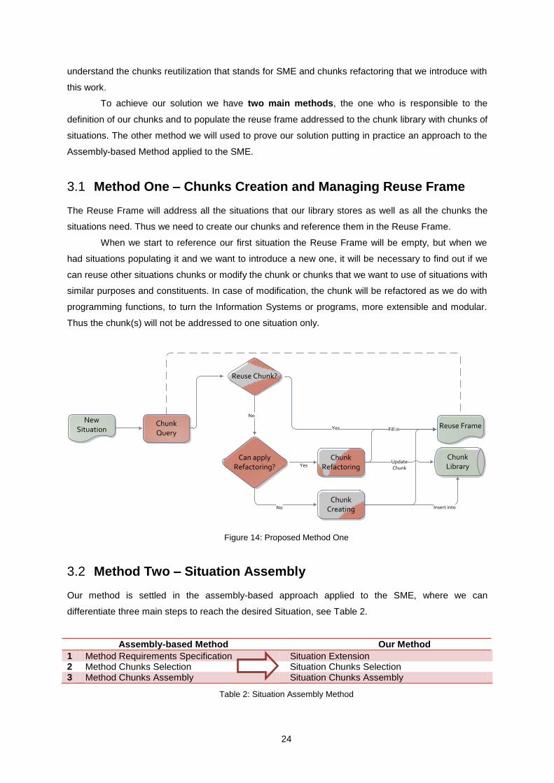
Method One – Chunks Creation and Managing Reuse Frame 3.1
The Reuse Frame will address all the situations that our library stores as well as all the chunks the
situations need. Thus we need to create our chunks and reference them in the Reuse Frame.
When we start to reference our first situation the Reuse Frame will be empty, but when we
had situations populating it and we want to introduce a new one, it will be necessary to find out if we
can reuse other situations chunks or modify the chunk or chunks that we want to use of situations with
similar purposes and constituents. In case of modification, the chunk will be refactored as we do with
programming functions, to turn the Information Systems or programs, more extensible and modular.
Thus the chunk(s) will not be addressed to one situation only.
Reuse Chunk?
Chunk Query
Yes
No
Can apply Refactoring?
Chunk RefactoringYes
UpdateChunk
ChunkCreating
NewSituation
ChunkLibrary
Reuse Frame
No Insert into
Fill in
Figure 14: Proposed Method One
Method Two – Situation Assembly 3.2
Our method is settled in the assembly-based approach applied to the SME, where we can
differentiate three main steps to reach the desired Situation, see Table 2.
Assembly-based Method Our Method
1 Method Requirements Specification Situation Extension 2 Method Chunks Selection Situation Chunks Selection 3 Method Chunks Assembly Situation Chunks Assembly
Table 2: Situation Assembly Method
25
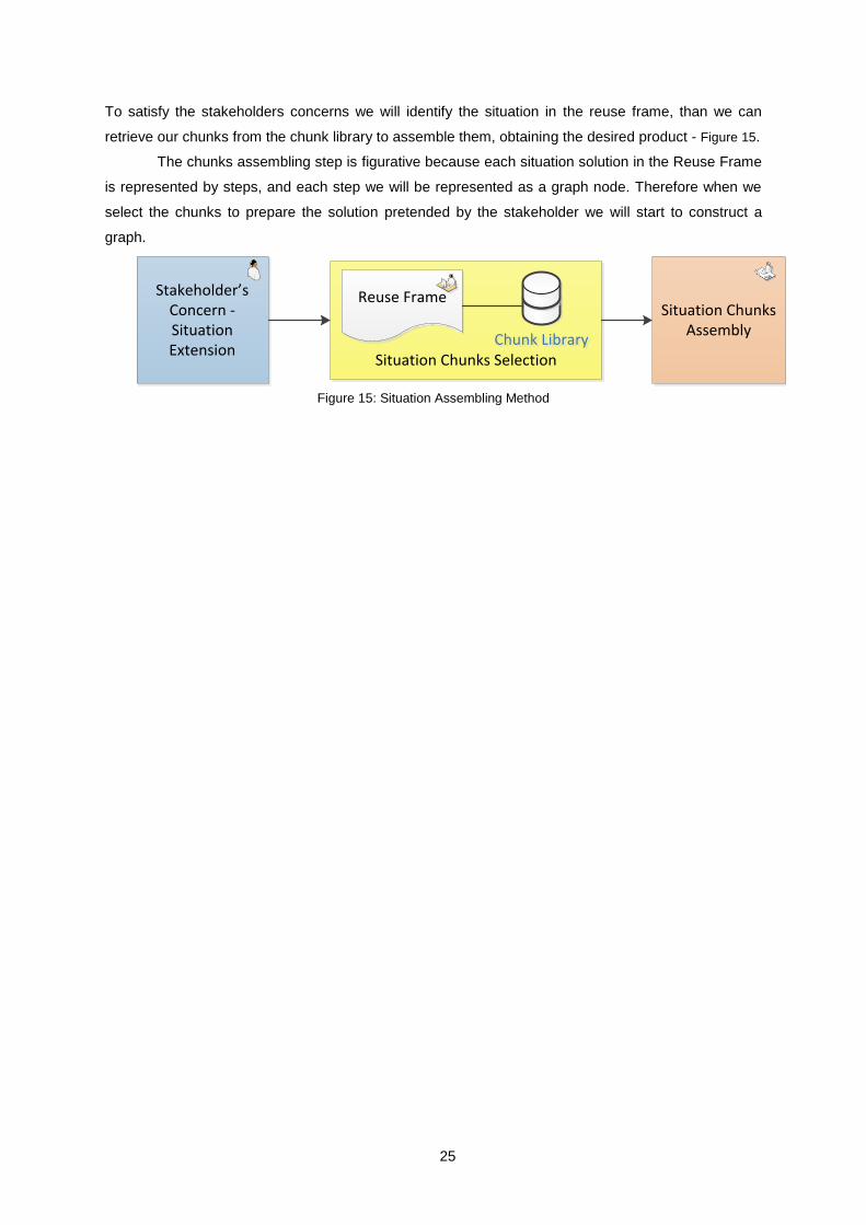
To satisfy the stakeholders concerns we will identify the situation in the reuse frame, than we can
retrieve our chunks from the chunk library to assemble them, obtaining the desired product - Figure 15.
The chunks assembling step is figurative because each situation solution in the Reuse Frame
is represented by steps, and each step we will be represented as a graph node. Therefore when we
select the chunks to prepare the solution pretended by the stakeholder we will start to construct a
graph.
Situation Chunks Selection
Situation Chunks Assembly
Reuse FrameStakeholder’s Concern - Situation Extension
Chunk LibraryChunk Library
Figure 15: Situation Assembling Method

26
4 Method Usage
Introducing one Situation to use our Methods One and Two, with the Library and the Reuse Frame
empty, we propose to identify Break Points on a Business Process Diagram. Starting to represent
some of the chunks by functions written in a generic programming language and aiming to fill into the
Reuse Frame, to finally represent some of those chunks prepared to be applied on our situation. To
illustrate the example scenarios we used ArchiMate components as a familiar language to us in the
academic environment.
Situation One - Break Points Identification 4.1
Break Points as an Analysis Points of a Business Process are defined as:
The points where a BP crosses Organizational Units. Typically in these points we may find
performance issues. The objective is to minimize the Break Points number, that is to minimize the
Organizational Units evolved in a process [28].
To identify the break points we propose following the steps listed below:
1) Organizational Unit identification;
2) Actors identification;
3) Map Actors vs OU's;
4) Identify which activities each actor executes;
5) Identify activities and relations between them;
6) Decompose activities while they are executed by actors from different organizational units.
The algorithm to decompose activities allowing us to identify break points is represented by Figure 16.

27
/*****************************************
* Algorithm: Break Points identification *
* Argument: Macroprocess M *
/*****************************************/
Activities activities[] = activities;
BreakPoint breakPoints[];
int pos = 0;
function breakPoint(){
for(int i = 0; activities > 0 ; i++){
activityDecomposition(activities[i])
activities--;
}
}
/*
activityDecomposition: decompose activities to identify the break
points taking account the sub-activities control flow that compose the main
activity, identifying the transitions between them which represent
breakpoints too
*/
function BreakPoint activityDecomposition(Activity activity){
if(actors from different OU's > 0){
breakPoints[pos] = BreakPoint;
pos++;
return
activityDecomposition(activity);
else
return 0;
}
}
Figure 16: Break Points Algorithm
To show an example of the Break Point Algorithm execution we can see Figure 17. It
illustrates possible decompositions of an Activity from a business process – Activity1, which is
performed by actors from different organizational units - Actor1 and Actor2. Until the algorithm stops
we are capable to identify the break points.
By the definition we differentiate four break points in the figure below:
1) Break Point [(Actor1, Actor2), Activity1]
2) Break Point [(Actor1, Actor2), Activity1']
3) Break Point [(Actor1, Actor2),transition(Activity1',Activity1'')]
4) Break Point [(Actor1, Actor2),transition(Activity1' *,Activity1' **)]

28
Figure 17: Break Points Algorithm execution example
S1 - C1
(Break Points Identification , Organizational Units
identification)
(Organizational Units )
S1 - C5
(Break Points Identification , Activities and relations between
them identification)
(Activities and Relations)
S1 - C6
(Break Points Identification , Break Points identification )
(Decompose activities while they are executed by actors from different organizational
units, identifying the breakpoints taking account the sub-activities control flow that
compose the main activity, identifying the transitions which some of that may represent
breakpoints too
, Break Points )
Figure 18: Situation Chunks example from S1
29
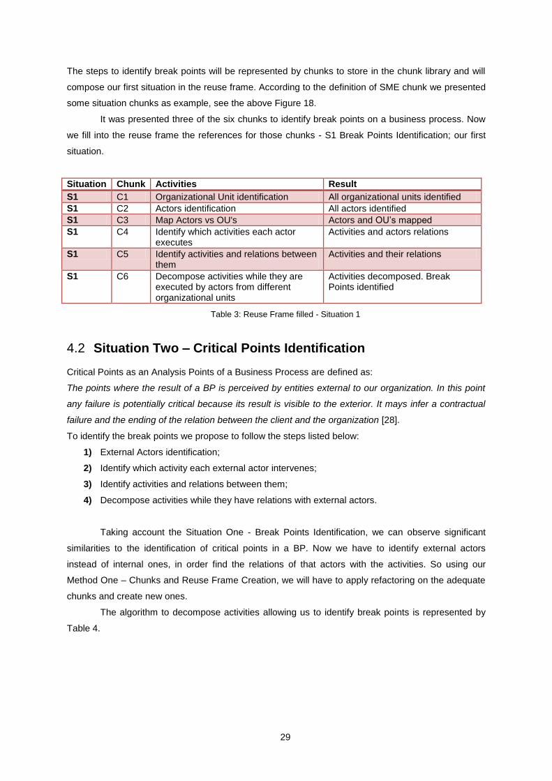
The steps to identify break points will be represented by chunks to store in the chunk library and will
compose our first situation in the reuse frame. According to the definition of SME chunk we presented
some situation chunks as example, see the above Figure 18.
It was presented three of the six chunks to identify break points on a business process. Now
we fill into the reuse frame the references for those chunks - S1 Break Points Identification; our first
situation.
Situation Chunk Activities Result
S1 C1 Organizational Unit identification All organizational units identified
S1 C2 Actors identification All actors identified
S1 C3 Map Actors vs OU's Actors and OU’s mapped
S1 C4 Identify which activities each actor executes
Activities and actors relations
S1 C5 Identify activities and relations between them
Activities and their relations
S1 C6 Decompose activities while they are executed by actors from different organizational units
Activities decomposed. Break Points identified
Table 3: Reuse Frame filled - Situation 1
Situation Two – Critical Points Identification 4.2
Critical Points as an Analysis Points of a Business Process are defined as:
The points where the result of a BP is perceived by entities external to our organization. In this point
any failure is potentially critical because its result is visible to the exterior. It mays infer a contractual
failure and the ending of the relation between the client and the organization [28].
To identify the break points we propose to follow the steps listed below:
1) External Actors identification;
2) Identify which activity each external actor intervenes;
3) Identify activities and relations between them;
4) Decompose activities while they have relations with external actors.
Taking account the Situation One - Break Points Identification, we can observe significant
similarities to the identification of critical points in a BP. Now we have to identify external actors
instead of internal ones, in order find the relations of that actors with the activities. So using our
Method One – Chunks and Reuse Frame Creation, we will have to apply refactoring on the adequate
chunks and create new ones.
The algorithm to decompose activities allowing us to identify break points is represented by
Table 4.

30
/********************************************
* Algorithm: Critical Points identification *
* Argument: Macroprocess M *
/********************************************/
Activities activities[] = activities;
CriticalPoint criticalPoints[];
int pos = 0;
function criticalPoint(){
for(int i = 0; activities > 0 ; i++){
activityDecomposition(activities[i],externalActors)
activities--;
}
}
/*
ActivityDecomposition: decomopose activities identifying critical
points
*/
function activityDecomposition(Activity activity){
if(activity involves one or more external actors){
criticalPoints[pos] = CriticalPoint;
pos++;
return
activityDecomposition(activity,externalActors);
}
else
return 0;
}
Table 4: Critical Points Algorithm
To show an example of the Break Point Algorithm execution we can look at Figure 19. It
illustrates possible decompositions of an Activity from a business process – Activity1, which have an
external actor and two internal actors as participants – ExternalActor1, Actor1 and Actor2
respectively. Until the algorithm stops we are capable to identify the critical points.
By the definition we can differentiate two critical points in the figure below:
1) Critical Point [ExternalActor1, Activity1]
2) Critical Point [ExternalActor1, Activity2]

31
Figure 19: Critical Points Algorithm execution example
As mentioned before, we can observe that algorithm to identify break points is very similar to
the algorithm of Critical points identification. Both of them decompose activities but have different
predicate in the conditional statement. According to that we propose to apply refactoring to the chunk
that represents the Break Point Algorithm, allowing it to identify critical points too, Table 5.

32
/******************************************************
* Algorithm: Break or Critical Points identification *
* Argument: Macroprocess M *
/*****************************************************/
Activities activities[] = activities;
Point points[];
Boolean externalActors; // true - Critical Points, false - Break Points
int pos = 0;
function Point(){
for(int i = 0; activities > 0 ; i++){
activityDecomposition(activities[i],externalActors)
activities--;
}
}
/*
activityDecomposition: decompose activities allowing to identify the
break points or critical points. In the case of break points we need to
take account the sub-activities control flow that compose the main
activity, identifying the transitions between them which represent
breakpoints too
*/
function activityDecomposition(Activity activity,int externalActors){
if(externalActors == false){
if(actors from different OU's > 0){
point[pos] = Point;
pos++;
return
activityDecomposition(activity,externalActors);
}
else
return 0;
}
else if(activity involves one or more external actors){
point[pos] = Point;
pos++;
return
activityDecomposition(activity,externalActors);
}
else
return 0;
}
Table 5: Break and Critical Points Algorithm
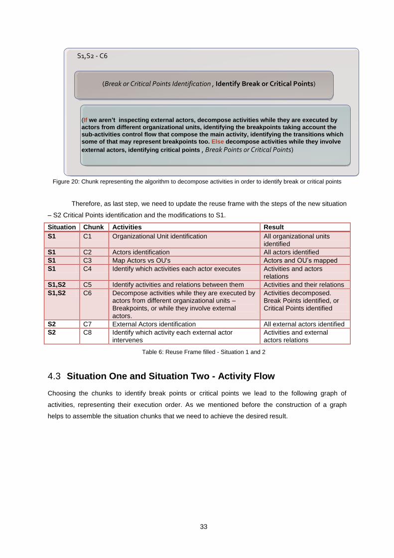
Now we need to rebuild the chunk for activities decomposition of Situation One and build the
chunks to the critical points identification in order to reference them in the reuse frame. The most
relevant step in the merge of the two situations is the algorithm presented before, so we represent on
Figure 20 the respective library chunk refactored from the Situation One. The remaining new chunks
as they have trivial representations we don’t illustrate it, there will be references of them in the
reconstructed reuse frame.
33
S1,S2 - C6
(Break or Critical Points Identification , Identify Break or Critical Points)
(If we aren’t inspecting external actors, decompose activities while they are executed by
actors from different organizational units, identifying the breakpoints taking account the
sub-activities control flow that compose the main activity, identifying the transitions which
some of that may represent breakpoints too. Else decompose activities while they involve
external actors, identifying critical points , Break Points or Critical Points)
Figure 20: Chunk representing the algorithm to decompose activities in order to identify break or critical points
Therefore, as last step, we need to update the reuse frame with the steps of the new situation
– S2 Critical Points identification and the modifications to S1.
Situation Chunk Activities Result
S1 C1 Organizational Unit identification All organizational units identified
S1 C2 Actors identification All actors identified
S1 C3 Map Actors vs OU's Actors and OU’s mapped
S1 C4 Identify which activities each actor executes Activities and actors relations
S1,S2 C5 Identify activities and relations between them Activities and their relations
S1,S2 C6 Decompose activities while they are executed by actors from different organizational units – Breakpoints, or while they involve external actors.
Activities decomposed. Break Points identified, or Critical Points identified
S2 C7 External Actors identification All external actors identified
S2 C8 Identify which activity each external actor intervenes
Activities and external actors relations
Table 6: Reuse Frame filled - Situation 1 and 2
Situation One and Situation Two - Activity Flow 4.3
Choosing the chunks to identify break points or critical points we lead to the following graph of
activities, representing their execution order. As we mentioned before the construction of a graph
helps to assemble the situation chunks that we need to achieve the desired result.

34
C1 C2 C3 C4
C5
C7 C8
C6
S1
S2
S1, S2
Key:
Figure 21: Situation One and Situation Two - Activity Flow

35
5 Applications
In the context of this work, we are about to prove the use of SME to obtain views over a model in a
consistent way. Therefore we use the Situation One and Situation Two of our method usage to
support our work.
Taking account S1 – Break Points Identification of the previous chapter, when we decompose
activities and represent the connections between them and the organization actors, basically we are
representing actor collaborations, no matter if the actors belong to different organizational units.
Therefore with some adjustments on S1 chunks we propose to reach the design of actor cooperation
views using the SME.
Situation One - Actor Cooperation Viewpoint 5.1
The viewpoint to construct an actor cooperation view, according to the conventions of constructing its
views, covering the relations between the organization actors, which is important to identify internal
dependencies. The organization environment will be addressed further to other viewpoint in our work.
In terms of internal actors’ cooperation as mentioned before will be adjusted our S1 - Break
Points Identification steps (chunks) to provide the guidelines to construct an internal actor cooperation
view, being our new S1 - Actor Cooperation Viewpoint.
When searching for breakpoints in a BP and decomposing activities, if a break point is
identified that is not a transition between activities but an activity performed by actors from different
OU’s, in fact we have located a collaboration. But in this specific situation, a collaboration can be
performed by actors from the same OU. Therefore adapting S1 we propose the following steps:
1) Internal Actors identification;
2) Identify which activities each actor executes;
3) Identify activities and relations between them;
4) Decompose activities while they are executed by more than one actor. When the activity
decomposition stops, the cooperation will be represented in the step immediately before an
activity or activities are being executed by one actor only.
Following the steps for this situation will be obtained the model represented by Figure 22.
But our objective is to obtain a view for actor cooperation, thus as the last step indicates, the
collaboration is one state before the last decomposition that present activities performed by one
actor. The actor cooperation view is represented on Figure 23.
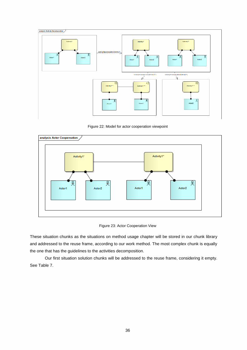
36
Figure 22: Model for actor cooperation viewpoint
Figure 23: Actor Cooperation View
These situation chunks as the situations on method usage chapter will be stored in our chunk library
and addressed to the reuse frame, according to our work method. The most complex chunk is equally
the one that has the guidelines to the activities decomposition.
Our first situation solution chunks will be addressed to the reuse frame, considering it empty.
See Table 7.

37
Situation Chunk Activities Result
S1 C1 Internal Actors identification All internal actors identified
S1 C2 Identify which activities each actor executes
Activities and actors relations
S1 C3 Identify activities and relations between them
Activities and their relations
S1 C4 Decompose activities while they are executed by more than one actor. When the activity decomposition stops, the cooperation will be represented in the step immediately before an activity or activities being executed by one actor only
Actor cooperation view designed
Table 7: Reuse Frame filled with Situation 1 – Actor Cooperation Viewpoint
Situation Two - Context Diagram Viewpoint 5.2
The viewpoint to construct an actor cooperation view, according to the conventions of constructing its
views, we need to identify the relations between the organization and its environment. A common
example of this is what is usually called Context Diagram, which puts an organisation into its
environment, i.e. customers, suppliers, and other business partners. It is useful to determine external
dependencies and collaborations, showing the value chain or network where the organisation
operates [29].
In this work we introduced a situation which proposes the identification of critical points in a
BP, where can be perceived the relations between the organization and its environment – S2 Critical
Points identification. Once again, but with S2, adjusting its chunks to the new situation extension, we
aim to obtain a view with an enterprise context diagram.
We propose the following steps to the build a context diagram:
1) External Actors identification;
2) Identify which activity each external actor intervenes;
3) Identify activities and relations between them;
4) Decompose activities while they have relations with external actors. When the activity
decomposition stops, the external relations will be in the step immediately before an activity
has no relations with its environment.
Following the steps – chunks, for this situation will be obtained the model represented by
Figure 19. To finish with a context diagram view, following the fifth chunk, will be represented the
environment relations, only. See Figure 24.

38
Figure 24: Context Diagram
The situation addressed above has similarities with S1 - Actor Cooperation Viewpoint.
Beyond the possible common chunks, the one that has the instructions to decompose activities and
identify actor cooperation can be refactored to identify relations with the organization environment. So
we propose the chunk representation on Figure 25.
S1,S2 – C4
(Actor Cooperation or Context Diagram Viewpoint, Build an Actor Cooperation View or Context Diagram)
(If we aren’t inspecting external actors relations, decompose activities while they are executed by more
than one actor. When the activity decomposition stops, the cooperation will be represented in the step
immediately before an activity or activities being executed by one actor only. Else, decompose activities
while they have relations with external actors. When the activity decomposition stops, the external
relations will be in the step immediately before an activity has no relations with its environment , Actor Cooperation or Context Diagram View)
Figure 25: Chunk representing the algorithm to decompose activities in order to identify relations between actors
and the organization environment
Now we are capable to update the reuse frame new situation steps – S2 Context Diagram
Viewpoint, and S1 modifications.

39
Situation Chunk Activities Result
S1 C1 Internal Actors identification All internal actors identified
S1 C2 Identify which activities each actor executes
Activities and actors relations
S1,S2 C3 Identify activities and relations between them
Activities and their relations
S1,S2 C4 Decompose activities while they are executed by more than one actor. When the activity decomposition stops, the cooperation will be represented in the step immediately before an activity or activities being executed by one actor only. Or decompose activities while they have relations with external actors. When the activity decomposition stops, the external relations will be in the step immediately before an activity has no relations with its environment
Actor cooperation view or a context diagram designed
S2 C5 External Actors identification All external actors identified
S2 C6 Identify which activity each external actor intervenes
Activities and external actors relations
Table 8: Reuse Frame filled - Situation 1 and 2 of Applications Chapter
Situation One and Situation Two - Activity Flow 5.3
Choosing the chunks to obtain an actor cooperation view or a context diagram we lead to the
following graph of activities, representing their execution order, helping us to assemble the situation
chunks achieving the desired result.
C1 C2
C3
C5 C6
C4
S1
S2
S1, S2
Key:
Figure 26: Situation One and Situation Two - Activity Flow

40
6 Conclusions
In this work we applied the Situational Method Engineering to obtain consistent methods to generate
views over BPD’s or other EA diagrams. So we proposed two methods - the one which allows us to
make a heterogenic and extensible chunk library, where we can reuse and modify the chunks
according the situations needs, and the other one which is based in the SME assembly-based
methodology.
Finally we have answered our research question - Is the SME a mechanism that allows us to
generate views over the same Business Process Model in a consistent way? Using our proposed
methods we can generate consistent views with well-defined guidelines.
Validation 6.1
To validate our work basing on the solutions and situations presented along this document, we
explain the answers that were proposed in first instance to the addressed thesis problem.
Q1: Is it possible to specify a view based in a method or mechanism?
H1: Create methods to obtain views, decomposing viewpoints in chunks.
In chapter 5, presenting the situations One and Two, respectively on section 5.1 and 5.2, we
proposed two methods leading to two different viewpoints. The structural parts of the viewpoints are
the chunks we have made, representing steps to obtain the desired views. We have used the
proposed method on section 3.1, to create the chunks and the method on 3.2 to assemble the
chunks.
Q2: Can we construct a library with viewpoint chunks?
H2: Use the chunks created in H1 to populate the library.
We used the proposed method on section 3.1, starting with the reuse frame empty and adding
situation chunks obtained on chapter 5, based in the situations chunks and algorithms presented on
chapter 4. In section 4.1 we presented a method to identify break points and in section 4.2 for critical
points, both with a macroprocess as input.
Q3: Is it possible to apply refactoring over a library of viewpoint chunks?
H3: Use the chunks of H2 modifying them to reuse in the maximum number of viewpoints -
situations.
With the obtained chunks on chapter 5 situations, we modified and adapt them to fit both situations.
As mentioned before we used our proposed method on chapter 3.1.

41
Contributions 6.2
As main contributions of this work we present the following:
The usage of SME adapted to viewpoints creation using the concepts of refactoring and
reutilization;
An incremental library;
The context diagram of an organization as well as the actor cooperation viewpoint, basing on
critical points and break points identification. Following the steps and algorithms proposed
trough chapters 4 and 5;
A method to obtain views.
In sum, we are capable to ask the same stakeholders to construct an organization context
diagram or other view over the same model and they may be capable to reach the same view.
This work guarantees that we may use a mechanism to obtain consistent views over
BPD’s or other diagrams over EA. The quality of the diagrams where we aim to obtain views is
not relevant; the important is the final result, in other words, the obtained view.
Future Work 6.3
To a better support of our solution’s methodology we may show other viewpoints as Business Process
Goals, Activities Inputs and Outputs or any other viewpoint over Enterprise Architecture models,
populating the chunk library and contributing to its heterogeneity and adaptability. In on other words,
the library will be populated with a bigger number of chunks, with a better adaptability to new
situations.

42
7 References
1. Dietz, J. L. G., Hoogervorst, J. A. P.: Enterprise Ontology and Enterprise Architecture – how
to let them evolve into effective complementary notions. GEAO Journal of Enterprise
Architecture, Vol. 1 (2007)
2. Lankhorst, M., et al.: Enterprise Architecture at Work, pp. 88—94. Springer, Heidelberg, ISBN
978-3-642-01309-6 (2009)
3. Hilliard, R.: All About IEEE Std 1471 (2007)
4. Mirbel, I., Ralyte, J.: Situational method engineering: combining assembly-based and
roadmap-driven approaches. Springer, London (2005)
5. Becker, J., Knackstedt, R., Pfeiffer, D., Janiesch, C.: Configurative Method Engineering – On
the Applicability of Reference Modelling Mechanisms in Method Engineering (2007)
6. Bucher, T., Klesse, M., Kurpjuweit, S., Winter, R.: Situational Method Engineering On the
Differentiation of Context and Project Type. University of St. Gallen (2007)
7. Brinkkemper, S., Saeki, M., Harmsen, F.: Assembly Techniques for Method Engineering.
Springer, Heidelberg (1998)
8. Nehan, Y., Deneckere, R.: Component-based Situational Methods – A framework for
understanding SME. CRI, University of Paris (2009)
9. Mirbel, I.: Method Chunk Federation. Sophia Antipolis (2006)
10. Braun C., Wortmann, F., Hafner, M., Winter, R.: Method Construction – A Core Approach to
Organizational Engineering. University of St. Gallen (2005)
11. Henderson-Sellers, H., Ralyte, J.: Situational Method Engineering: State-of-the-Art Review.
Journal of Universal Computer Science, Vol. 16, No. 3 (2010)
12. Lankhorst, M., et al.: Enterprise Architecture at Work, pp. 54—72. Springer, Heidelberg, ISBN
978-3-642-01309-6 (2009)
13. Hilliard, R.: Aspects, Concerns, Subjects, Views, ... *. Integrated Systems and Internet
Solutions, Inc., Massachusetts (1999)
14. Maier, M., Emery, D., Hilliard, R.: ANSI/IEEE 1471 and Systems Engineering. Systems
Engineering, Vol. 7, No. 3 (2004)
15. Hoogervorst, J.A.P, Dietz, J.L.G.: Enterprise Architecture in Enterprise Engineering.
Enterprise Modelling and Information Systems Architecture, Vol. 3, No. 1 (2008)
16. Albani, A., Dietz, J., Hoogervorst, J., Mulder, H., Tribolet, J.: Enterprise Engineering – A
Manifesto. Enterprise Engineering Manifesto, version 5 (2009)
17. Winter, R., Fischer, R.: Essential Layers, Artifacts, and Dependencies of Enterprise
Architecture. Journal of Enterprise Architecture (2007)
18. Aier, S., Kurpjuweit, S., Saat, J., Winter, R.: Enterprise Architecture Design as an Engineering
Discipline. AIS Transactions on Enterprise Systems, Vol. 1 (2009)
19. Braun, C., Winter, R.: A Comprehensive Enterprise Architecture Metamodel and Its
Implementation Using a Metamodeling Platform. University of St. Gallen (2005)

43
20. Lankhorst, M., et al.: Enterprise Architecture at Work, Foreword to the Second Edition.
Springer, Heidelberg, ISBN 978-3-642-01309-6 (2009)
21. Steen, M.W.A., Strating, P., Lankhorst, M.M., Doest, ter H., Iacob, M.-E.: Service-Oriented
Enterprise Architecture. Telematica Instituut, The Netherlands (2004)
22. Lankhorst, M., et al.: Enterprise Architecture at Work, pp. 88—119. Springer, Heidelberg,
ISBN 978-3-642-01309-6 (2009)
23. Eriksson, H.-E., Penker, M.: Business Modeling with UML. Open Training (2000)
24. Caetano, A.: Business Process Modelling with Actors and Roles. PhD Thesis, pp. 70—104,
Instituto Superior Técnico (2008)
25. Korherr, B.: Business Process Modelling – Languages, Goals, and Variabilities. PhD Thesis,
pp. 10—14, Vienna University of Technology, Faculty of Informatics (2008)
26. Steen, M.W.A., Akehurst, D.H., ter Doest ,H.W.L., Lankhorst, M.M.: Supporting Viewpoint-
Oriented Enterprise Architecture. Telematica Instituut, The Netherlands (2004)
27. Winter, R., Gericke, A.: On the Application of the ISD Method Engineering Approach to
Organizational Engineering. Institute of Information Management University of St. Gallen
(2009)
28. Caetano, A., Sousa, P., Vasconcelos , A.: APFSI10-02-2.: Aula 10-12 - Especificação de
Processos de Negócio, Arquitectura Processos e Ferramentas de Sistemas de Informação.
Support Material, Instituto Superior Técnico (2010)
29. Lankhorst, M., et al.: Enterprise Architecture at Work, pp. 180—184. Springer, Heidelberg,
ISBN 978-3-642-01309-6 (2009)