the pittsburgh-florida state universities γ detection array
TRANSCRIPT
Nuclear Instruments and Methods in Physics Research B79 (1993) 821-824 North-Holland
NOM B Beam Interactions
with Mated&s & Atoms
The Pittsburgh-Florida State Universities y detection array *
S.L. Tabor, M.A. Riley, J. D&kg, P.D. Cottle, R. Books, T. Glasmacher, J.W. Holcomb, J. Hutchins, G.D. Johns, T.D. Johnson, T. Petters, 0. Tekyi-Mensah, P.C. Womble and L. Wright Physics Department, Florida State University, Tallahassee, Florida 32306, USA
J.X. Saladin Department of Physics, University of Pittsburgh, Pittsburgh, Pennsylvania 15260, USA
A y detector array for studying high-spin structure in nuclei has been constructed by combining detectors from hvo universities. The system contains 11 ~gh-resolution Ge detectors with BGO ~rnpton-suppression shields and 28 Iow-re~lution BGO scintillators to provide multiplici~ and sum energy information. A unique feature of the array is the heterogeneous nature of the detectors which were not originally purchased for such a system.
1. rntroduction
The Pitt-FSU ~mbined detector array represents a combining and sharing of resources between three universities to maximize the research potential. For approximately half of each year the six Compton-sup- pressed Ge detectors and fourteen multiplicity filters purchased by the University of Pittsburgh are com- bined with five FSU ~mpton-suppre~ed Ge detectors and fourteen multiplici~ filters to make one large more effective array for use on the FSU tandem super- conducting linac facility. During the other part of the year the Pittsburgh detectors are used at the University of Notre Dame Nuclear Physics Laboratory.
The purpose of the array is to measure coincidences between pairs of y-rays with high resolution, filtered by additional information concerning the number and total energy of other -y-rays emitted in the same event. The value of combining the detectors lies in the fact that the number of pairs increases approximately with the square of the number of detectors. Arrays of this type have been ~nstNcted at several laboratories [1,2], but not with such a heterogeneous collection of detec- tors.
2. Mechanical assembly
It was considered essential that an array of this complexity remain permanently set up during its pe-
* This work was supported in part by the U.S. National Science Foundation.
riod of operation, but the Ge diodes are rather sensi- tive to neutron damage. To shield the Ge detectors from neutron radiation from other e~e~ments in the target room, a separately shielded area was con- structed with surplus concrete blocks and a steel struc- ture for stabilization.
The mechanical assembly of the array presented a particular challenge because of the variety of Ge detec-
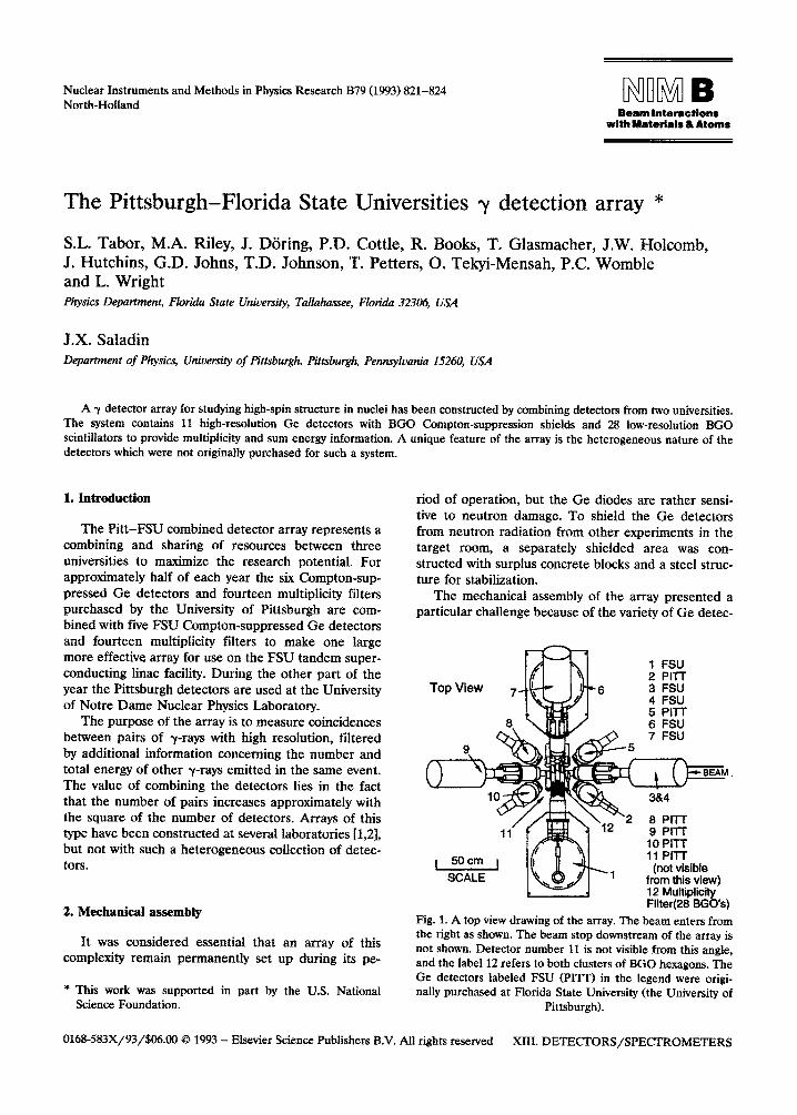
1 FSU 2 PITT 3 FSU 4 FSU 5 PI-l-l- 6 FSU 7 FSU
-5
2 8 PITT 9 PITT io PITT 11 PI-l-r
(not visible from this view) 12 Multiplicity Fllter(28 BGOk)
Fig. 1. A top view drawing of the array. The beam enters from the right as shown. The beam stop downstream of the array is not shown. Detector number 11 is not visible from this angle, and the label 12 refers to both clusters of BGO hexagons. The Ge detectors labeled FSU (PIIT) in the legend were origi- nally purchased at Florida State University (the University of
Pittsburgh).
Old-583X/93/$~.~ 8 1993 - Elsevier Science Publishers B.V. All rights reserved XIII. DETE~ORS/SPE~ROME~RS
822 S.L. Tabor et al. / The Pitt-FSU y detection array
tors and Compton suppressors being used. About half the Compton suppressors are cylinders of BGO with a bore hole along the axis for the Ge crystal, while the bore hole is perpendicular to the cylinder axis in the other half of the BGO crystals. Most of the liquid nitrogen cryostats for cooling the Ge detectors have a cylindrical shape whose axis is parallel to that of the cylindrical Ge crystals, but these axes are perpendicu- lar for several of the detectors. There are also three different cryostat sizes ranging in capacity from 3 to 30 1.
Other design criteria were to limit the number of angles between the detectors and the beam direction
to three and to limit the detector to target distance to preserve solid angle. The mechanical design is shown in fig. 1. There are four detector positions at 35”, four at 90” and four at 145”, all with a minimum distance to target of 18 cm. The extra detector position will allow future placement of a planar Ge detector which is optimized for the detection of lower energy y-rays or another Compton-suppressed Ge detector.
A new beam line was constructed for the array at an angle of 22.5” on the switching magnet. Vacuum pumps, quadrupole lenses and other components for the beam line were provided by the University of Pittsburgh. A supplementary grant from the National Science Foun-
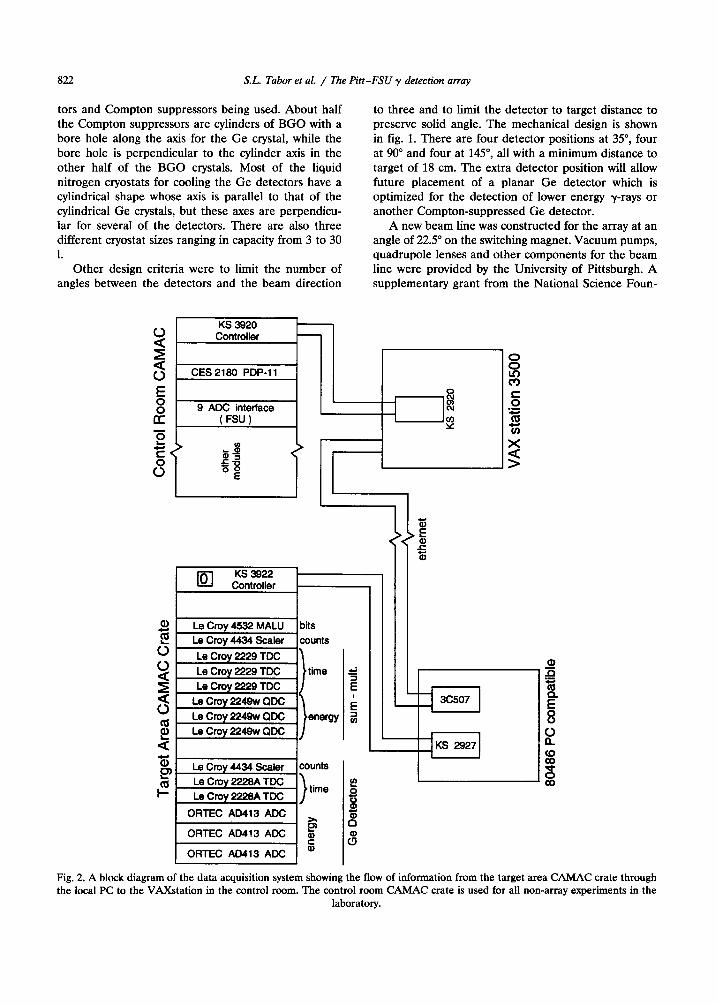
KS 3920 Controller
3 0 CES 2130 PDP-11
8
E z
8 9 ADC interface z 8 s -=
CT (FSU) B (u
2 ?i
E u)
$4 <’
s +jz
E
Fig. 2. A block diagram of the data acquisition system showing the flow of information from the target area CAMAC crate through the local PC to the VAXstation in the control room. The control room CAh4AC crate is used for all non-array experiments in the
laboratory.
S.L. Tabor et al. / l?ze Pitt-FSU y detection array 823
dation helped complete the construction of the array and beam line and electronics system.
A simple manual liquid nitrogen (LN) filling system was designed and constructed by graduate students. Manual valves on a manifold direct LN from a pressur- ized tank through permanent plumbing to the detec- tors and onto a gas discharge manifold.
3. High resolution detectors
The eleven Compton-suppressed Ge detectors pro- vide the heart of the array. All have fairly similar Ge crystals with efficiencies of 20-Z% relative to the standard NaI crystal and all use N-type Ge with the reverse electrode con~guration to rn~i~ze sensitivi~ to neutron damage. As mentioned earlier, the pack- ages into which the crystals are mounted differ consid- erably because the detectors were acquired over a period of time at two universities from a variety of funding sources including National Science Foundation grants, Florida State University funds and an NSF Presidential Young Investigator award.
To reduce background in the spectra due to events in which y-rays scatter out of the Ge crystals and deposit only part of their energy, each Ge crystal is surrounded by a bismuth germanate (BGO) scintillator to veto such events [31. About half of these have an annular shape, while the Ge detector is inserted into a hole perpendicular to the BGO axis in the other half. BGO is used because of its relatively high average atomic number and, therefore, y sensitivity. Absorp- tion lengths in BGO are about half those in NaI, the most commonly used scintillator. Peak to total ratios of about 50% are obtained for a 6oCo source.
A custom circuit was designed and constructed at FSU to perform all the logic for Compton suppression and coincidence selection. This circuit, which is imple- mented in transistor-transistor logic (ITL), provides variable pulse delays and widths to maximize the effi- ciency of the Compton veto for each channel. A multi- plicity selector determines the rnin~~ number of channels which must fire and then enables those chan- nels to generate gate pulses.
4. Low resolution detectors
Clusters of 28 BGG scintillators are used to esti- mate the total number of -y-rays emitted in an event and their total energy. The high efficiency of BGO makes these detectors ideal for counting the total number of photons and providing an approximate value of their total energy.
Fourteen hexagonal EGO crystals 2.6 cm on a side and 15.2 cm long were originally purchased by the
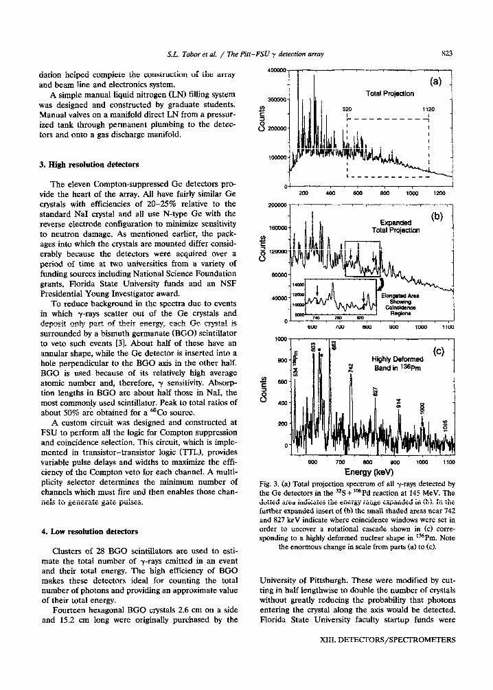
Total Projection
-I U.
200 400'6bJ'acQ IOk \--i
1200
16ww
m E a 12OOQo
0
8OOw
40000
0 800 7v0 800 SW i000 1lW
Highly Deformed Band in l36Prn
Fig. 3. (a) Total projection spectrum of all y-rays detected by the Ge detectors in the 32S + ‘“Pd reaction at 145 MeV. The dotted area indicates the energy range expanded in (b). In the further expanded insert of (bl the small shaded areas near 742 and 827 keV indicate where coincidence windows were set in order to uncover a rotational cascade shown in Cc) corre- sponding to a highly deformed nuclear shape in *36Pm. Note
the enormous change in scale from parts (a) to Cc).
University of Pittsburgh. These were modified by cut- ting in half lengthwise to double the number of crystals without greatly reducing the probability that photons entering the crystal along the axis would be detected. Florida State University faculty startup funds were
XIII. DE~~ORS/SPE~~ME~RS
824 S.L. Tabor et al. / The Pitt-FSU y detection array
used to cut the crystals and install new photomultiplier tubes on them. The assemblies were packaged in stain- less steel cylinders with plastic injection-molded end pieces. The crystals are grouped in two clusters of 14 elements each and placed at 90” to the beam axis.
The sum ener~-multiplici~ filter can be used in a variety of ways. A minimum number of elements firing can be required in hardware to allow events in the Ge detectors to be accepted, or the number of elements firing can be written to tape along with the high resolution data. Another option is to write the energies measured in each of the 28 elements to tape along with the Ge detector information.
5. Data acquisition
To reduce the number of long cables as well as problems with ground loops, the front end of the data acquisition system was placed near the array. Three Ortec AD413 quad analog-to-digital converters @DC) were purchased to digitize the signals from the Ge ~gh-re~lution detectors. These are CAMAC modules which can be read out over the CAMAC bus. Time and low-resolution detector information are digitized in other CAMAC modules. After the signals from an event are digitized, the information is read by a Kinetic Systems model KS3922 CAMAC controller connected to a KS2927 16-bit interface card in an 80486-based personal computer (PC). The PC serves as a very ~st-effective event builder which then sends buffers of data via Ethernet to a Digital Equipment Corporation VAXstation 3500 computer. Programs running in the VAX histogram the spectra to monitor the detectors and write the event data to an 8 mm tape drive. Another PC program allows for direct histogramming of spectra locally in the PC. This is valuable for setting up the array, calibrating detectors, optimizing Comp- ton suppression, etc. It operates independently of the VAX. A block diagram of the data acquisition system is shown in fig. 2.
The system works well and several improvements are planned to further increase the maximum data
rate. One is to place a SCSI interface in the PC so that event data can be written to tape locally and not have to pass over the Ethernet link. Another is to build a “dumb” PC to CAMAC interface to allow for faster readout of the crate and avoid limitations imposed by the Z80 S-bit processor in the KS3922 module.
6. Operation of the array
A wide variety of beams from the FSU tandem Linac accelerator can be brought into the array. Some of the more commonly used beams are 6,7Li, *2,13C, 16*180, 19F, 28*2gSi and 32S, although any ion up through Ni (except for inert gases) can be produced with an intensity depending on its production yield in the Cs sputter ion source. The maximum beam energies of 5-10 MeV/mass unit make it possible to produce nuclei of all masses with fusion-evaporation reactions.
The combined array was set up at FSU in late 1991 and early 1992 and was in operation approximately the first half of 1992. Although a silent amount of time was devoted to development during this “maiden voyage”, seven experiments were performed on the array, each lasting typically a week. Most involved studies of the structure of nuclei with mass numbers around 80 or 150.
An example of the performance of the system is given in fig. 3. It shows how a weakly populated, but very interesting, highly deformed rotational band in l”Prn can be studied with the array 141. The band in fig. 3c, like the proverbial needle, is pulled out of the “haystack” of fig. 3a by the coincidence gates.
References
fl] J.F. Sha~ey-shier and J. Simpson, Prog. Part. Nucl. Phys. 21 (1988) 293.
121 B. Herskind, Nucl. Phys. A447 (1985) 395. [3] S.L. Tabor, Nucl. Instr. and Meth. B24/25 (1987) 1031. [4] M.A. Riley et al., to be published.