understanding neutron radiography reading iii rev
Post on 17-Jul-2016
38 views
DESCRIPTION
Understanding Neutron Radiography Reading III RevTRANSCRIPT
Charlie Chong/ Fion Zhang
Understanding Neutron RadiographyReading III Rev.1My ASNT Level III, Pre-Exam Preparatory Self Study Notes 3 July 2015

Charlie Chong/ Fion Zhang http://homework55.com/apphysicsb/ap5-28-08/
Nuclear Source- Plasma Fusion

Charlie Chong/ Fion Zhang
Nuclear Source- Plasma Fusion

Charlie Chong/ Fion Zhang
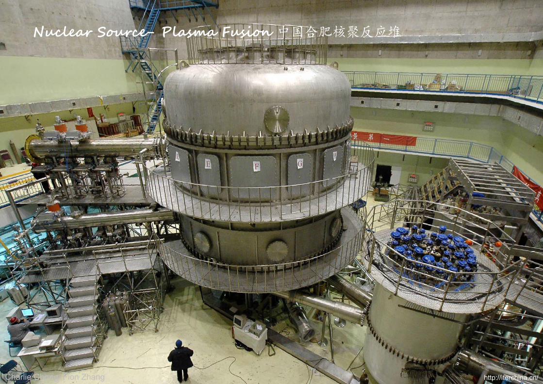
Nuclear Source- Plasma Fusion 中国合肥核聚反应堆
http://iterchina.cn/
Charlie Chong/ Fion Zhang
Nuclear Source- Plasma Fusion 中国合肥核聚反应堆
http://iterchina.cn/

Nuclear Source-Reactors
Charlie Chong/ Fion Zhang http://iterchina.cn/

Charlie Chong/ Fion Zhang
Nuclear Source-Reactors

Charlie Chong/ Fion Zhang http://homework55.com/apphysicsb/ap5-28-08/
Nuclear Source-Reactors

The Magical Book of Neutron Radiography
Charlie Chong/ Fion Zhang

Charlie Chong/ Fion Zhang
Charlie Chong/ Fion Zhang
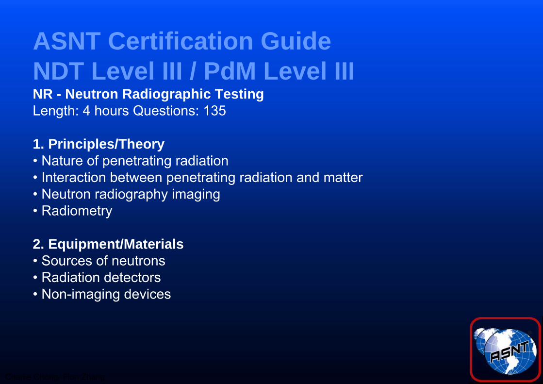
ASNT Certification GuideNDT Level III / PdM Level IIINR - Neutron Radiographic TestingLength: 4 hours Questions: 135
1. Principles/Theory• Nature of penetrating radiation• Interaction between penetrating radiation and matter• Neutron radiography imaging• Radiometry
2. Equipment/Materials• Sources of neutrons• Radiation detectors• Non-imaging devices

Charlie Chong/ Fion Zhang
• Electron emission radiography• Micro-radiography• Laminography (tomography)• Control of diffraction effects• Panoramic exposures• Gaging• Real time imaging• Image analysis techniques
3. Techniques/Calibrations• Blocking and filtering• Multifilm technique• Enlargement and projection• Stereoradiography• Triangulation methods• Autoradiography• Flash Radiography• In-motion radiography• Fluoroscopy

Charlie Chong/ Fion Zhang
4. Interpretation/Evaluation• Image-object relationships• Material considerations• Codes, standards, and specifications
5. Procedures• Imaging considerations• Film processing• Viewing of radiographs• Judging radiographic quality
6. Safety and Health• Exposure hazards• Methods of controlling radiation exposure• Operation and emergency procedures
Reference Catalog NumberNDT Handbook, Third Edition: Volume 4,Radiographic Testing 144ASM Handbook Vol. 17, NDE and QC 105

Charlie Chong/ Fion Zhang

Fion Zhang at Shanghai3th July 2015
http://meilishouxihu.blog.163.com/
Charlie Chong/ Fion Zhang

Greek Alphabet
Charlie Chong/ Fion Zhang

Charlie Chong/ Fion Zhang http://greekhouseoffonts.com/

Charlie Chong/ Fion Zhang

Charlie Chong/ Fion Zhang
Why Neutron Radiography?"finding lead in a paraffin block (or a needle in a haystack) would work for x rays while looking for paraffin in a lead block or a straw in a needle-stack would work for neutrons."

Charlie Chong/ Fion Zhang
Why Neutron Radiography?"finding lead in a paraffin block (or a needle in a haystack) would work for x rays while looking for paraffin in a lead block or a straw in a needle-stack would work for neutrons."

Charlie Chong/ Fion Zhang
Why Neutron Radiography?"finding lead in a paraffin block (or a needle in a haystack) would work for x rays while looking for paraffin in a lead block or a straw in a needle-stack would work for neutrons."
Charlie Chong/ Fion Zhang
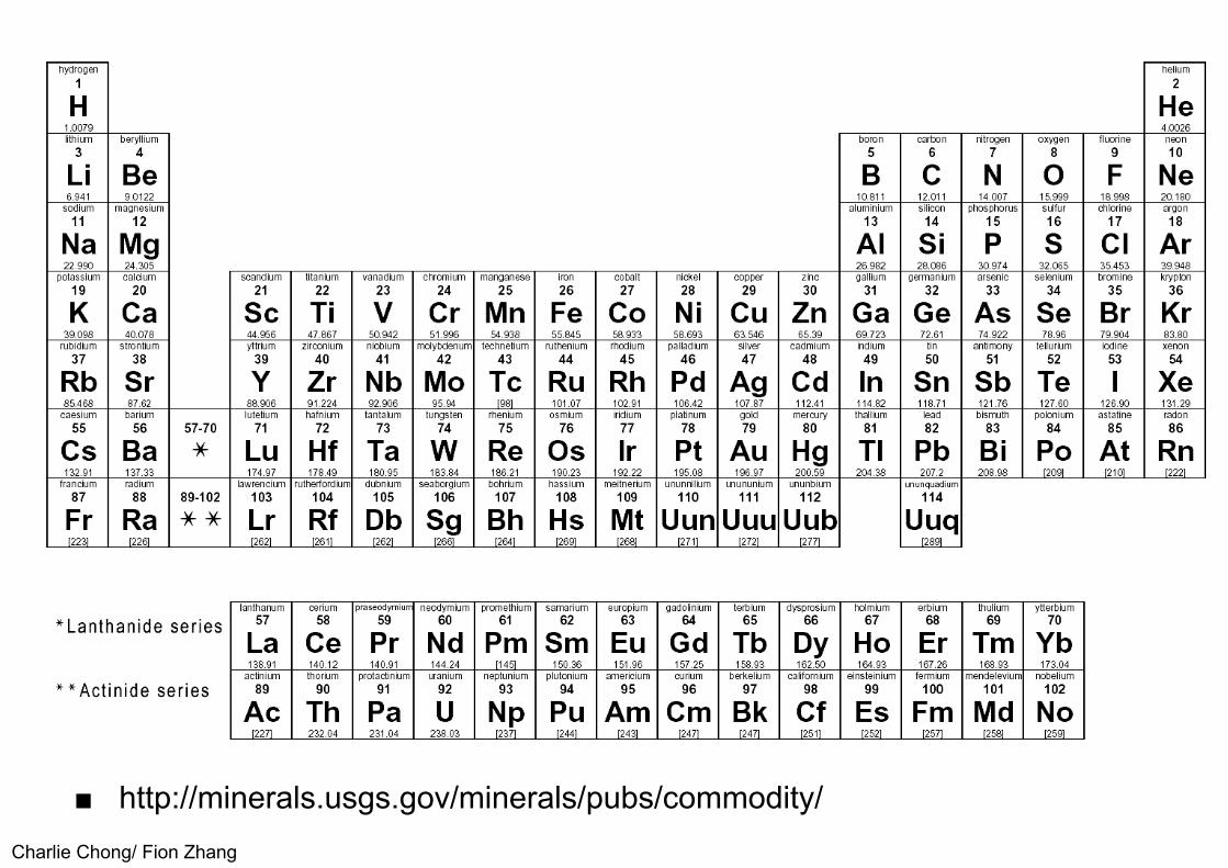
■ http://minerals.usgs.gov/minerals/pubs/commodity/

Charlie Chong/ Fion Zhang
Neutron Cross Section of the elements
■ http://periodictable.com/Properties/A/NeutronCrossSection.html

Charlie Chong/ Fion Zhang
Screen Types-11. Transfer screen-indium or dysprosium, In, Dy, Gold, Silver, Rhodium,
Europium, Samarium.2. Thermal neutron filter using Cadmium for epithermal neutron radiography,
Cd. Lithium resonance direct screen.3. Converter screen uses gadolinium which emit beta particles, γ, conversion
electron.4. the beta particles are caught by a fluorescing zinc sulfide material5. Scintillator screen: Zinc sulfide, Lithium carbonate, plastid scintillator,
Gadolinium oxysulfide.6. Accelerator (H+, 2H+)Target material: Beryllium, Be or lithium Li.7. Boron used for neutron shields.

Charlie Chong/ Fion Zhang
Screen Types-21. Beam filter, Beryllium thermalized thermal neutron further and pass only
cold neutron.2. Cadmium remove thermal & cold neutrons and pass epithermal neutrons.3. Fast neutron direct radiography used Tantalum or transfer radiography
with Holmium.4. Gadolinium Gd, conversion screens emit- (1) gamma rays and (2)
conversion electronn5. Dysprosium (165m
66Dy) conversion screens emit: (1) high-energy betas β, (2) low-energy gamma γ, and (3) internal-conversion electrons e-.

Charlie Chong/ Fion Zhang
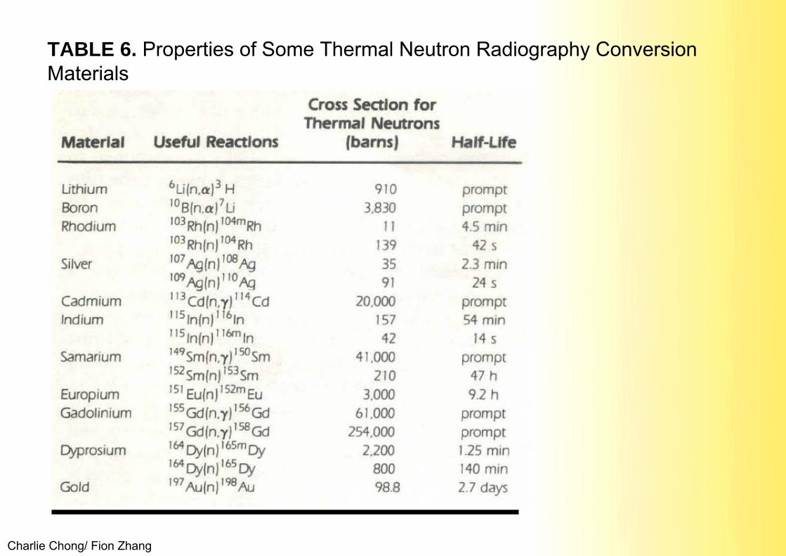
TABLE 6. Properties of Some Thermal Neutron Radiography Conversion Materials
promptprompt45 min42 s2.3 min24 sprompt54 min14 sprompt47 h9.2 hpromptprompt1.25 min140 min2.7 days
9103,830
111393591
20,00015742
41,000210
3,00061,000
254,0002,20080099
6Li(n,α) 3H10B(n,α) 7Li103Rh(n)104mRh103Rh(n)104Rh107Ag(n)108Ag109Ag (n)110 Ag113Cd((n,γ)114Cd115 In(n)116n115 In(n)116mln149Sm(n,γ) 150SmI52 Sm(n)153Sm151 Eu(n)152Eu155 Gd(n,γ) I56Gd157 Gd(n,γ)158Gd164 Dy(n)165mDy164 Dy(n)165Dy197 Au(n)198Au
LithiumBoronRhodium
Silver
CadmiumIndium
Samarium
EuropiumGadolinium
Dyprosium
Gold
LifeCross Section for Thermal Neutrons (barns)
Useful ReactionsMaterial

Charlie Chong/ Fion Zhang http://crete.homeip.net/show_nuclide/660465/
The letter m is sometimes appended after the mass number to indicate a nuclear isomer, a metastable or energetically-excited nuclear state (as opposed to the lowest-energy ground state), for example 165mDyhttps://en.wikipedia.org/wiki/Isotope
Charlie Chong/ Fion Zhang
TABLE 6. Properties of Some Thermal Neutron Radiography Conversion Materials

Charlie Chong/ Fion Zhang
IVONA TTS Capable.
http://www.naturalreaders.com/

Charlie Chong/ Fion Zhang
Reading IIIContent Reading One: ASNTHBVol4Chapter16 Reading Two: Assorted Reading Three: Neutron Radiography State of Art Report
- NTIAC-SR-98-01 Reading Four:

Charlie Chong/ Fion Zhang
Reading-1ASNTHBVol4Chapter16
Charlie Chong/ Fion Zhang
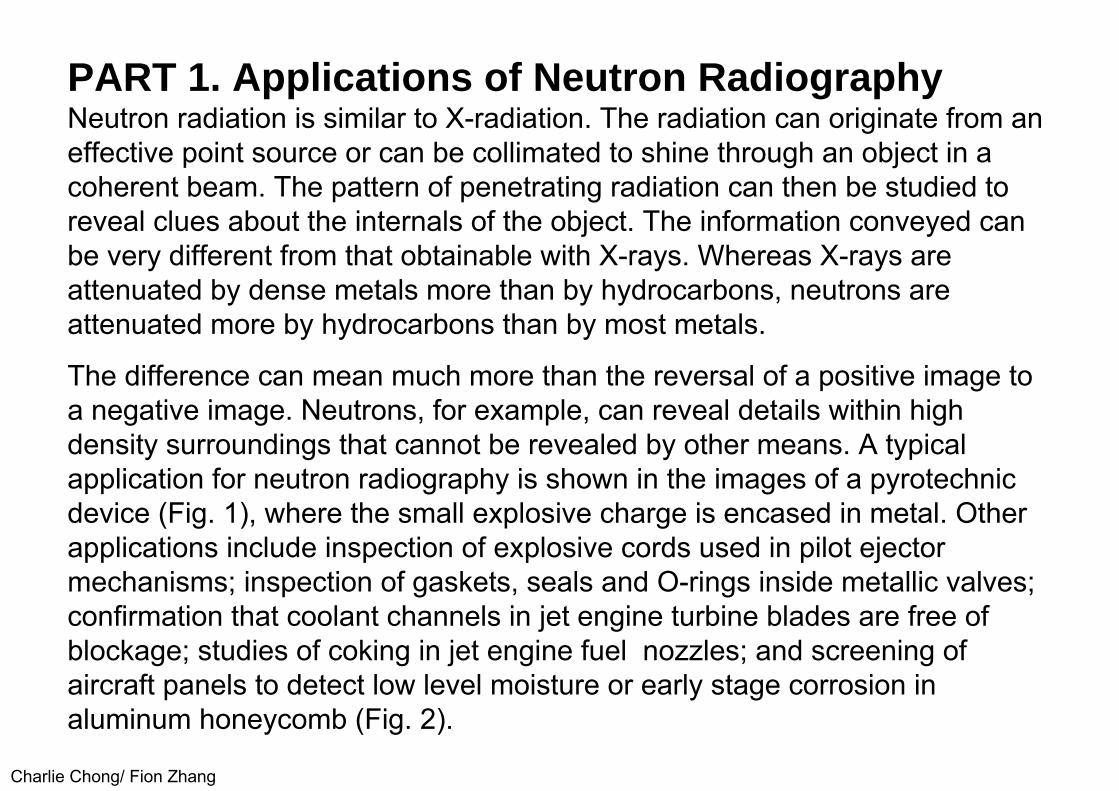
PART 1. Applications of Neutron RadiographyNeutron radiation is similar to X-radiation. The radiation can originate from aneffective point source or can be collimated to shine through an object in acoherent beam. The pattern of penetrating radiation can then be studied toreveal clues about the internals of the object. The information conveyed canbe very different from that obtainable with X-rays. Whereas X-rays areattenuated by dense metals more than by hydrocarbons, neutrons areattenuated more by hydrocarbons than by most metals.
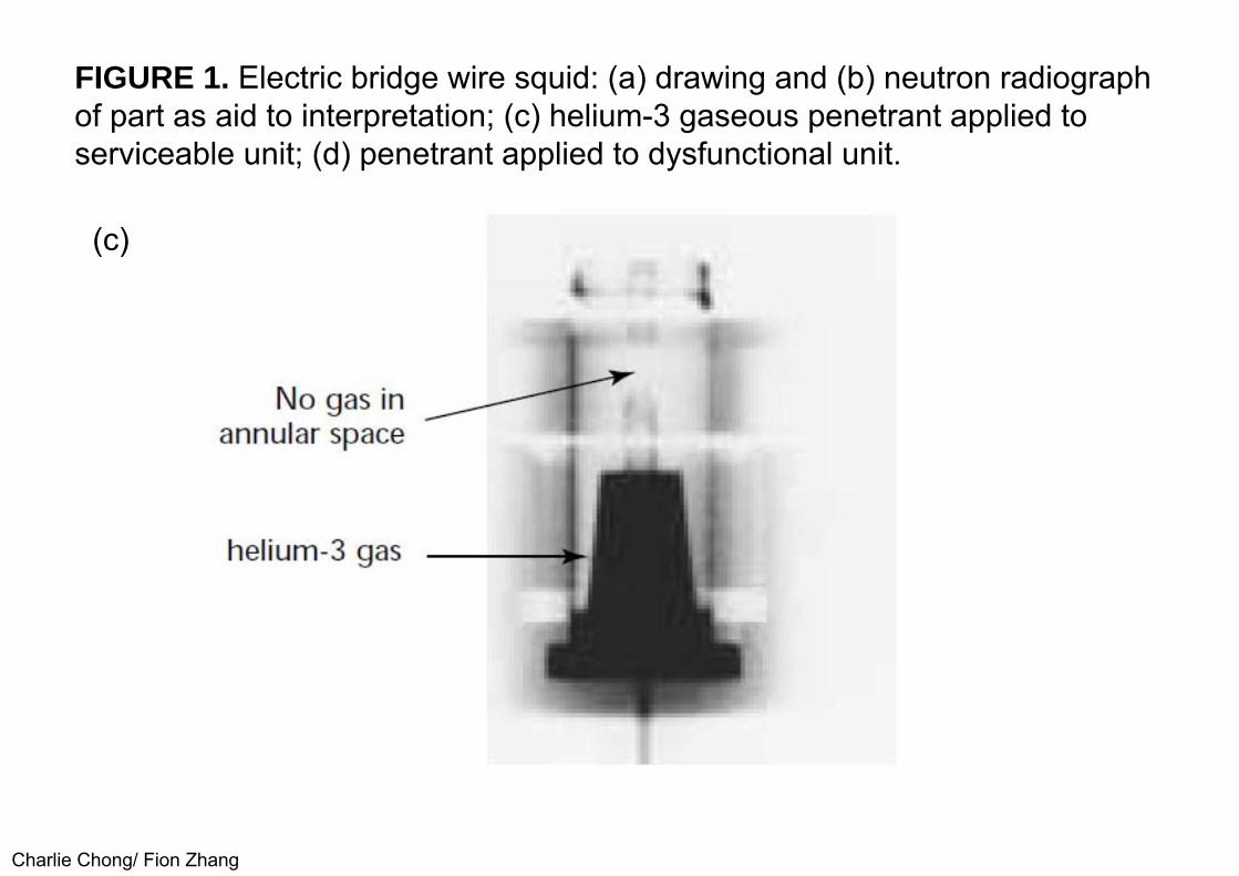
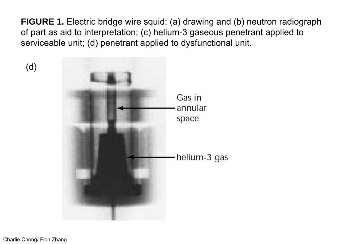
The difference can mean much more than the reversal of a positive image to a negative image. Neutrons, for example, can reveal details within high density surroundings that cannot be revealed by other means. A typical application for neutron radiography is shown in the images of a pyrotechnic device (Fig. 1), where the small explosive charge is encased in metal. Other applications include inspection of explosive cords used in pilot ejector mechanisms; inspection of gaskets, seals and O-rings inside metallic valves;confirmation that coolant channels in jet engine turbine blades are free of blockage; studies of coking in jet engine fuel nozzles; and screening of aircraft panels to detect low level moisture or early stage corrosion in aluminum honeycomb (Fig. 2).

Charlie Chong/ Fion Zhang
FIGURE 1. Electric bridge wire squid: (a) drawing and (b) neutron radiograph of part as aid to interpretation; (c) helium-3 gaseous penetrant applied toserviceable unit; (d) penetrant applied to dysfunctional unit.

Charlie Chong/ Fion Zhang
FIGURE 1. Electric bridge wire squid: (a) drawing and (b) neutron radiograph of part as aid to interpretation; (c) helium-3 gaseous penetrant applied toserviceable unit; (d) penetrant applied to dysfunctional unit.
(b)
Charlie Chong/ Fion Zhang
FIGURE 1. Electric bridge wire squid: (a) drawing and (b) neutron radiograph of part as aid to interpretation; (c) helium-3 gaseous penetrant applied toserviceable unit; (d) penetrant applied to dysfunctional unit.
(c)
Charlie Chong/ Fion Zhang
FIGURE 1. Electric bridge wire squid: (a) drawing and (b) neutron radiograph of part as aid to interpretation; (c) helium-3 gaseous penetrant applied toserviceable unit; (d) penetrant applied to dysfunctional unit.
(d)

Charlie Chong/ Fion Zhang
FIGURE 2. Comparison of neutron radiographs of moisture globules inaluminum honeycomb panel, later dried: (a) before processing; (b) afterprocessing.
(a)

Charlie Chong/ Fion Zhang
FIGURE 2. Comparison of neutron radiographs of moisture globules inaluminum honeycomb panel, later dried: (a) before processing; (b) afterprocessing.
(b)

Charlie Chong/ Fion Zhang
User’s GuideUnlike many other forms of nondestructive testing, neutron radiography is nota do-it-yourself technique. There have been neutron radiography servicecenters in the United States since 1968. To try out neutron radiography on anobject of interest, it is simply necessary to locate the services currentlyavailable and, if agreed, mail your item to them. Typically, the neutronradiograph and your item will be mailed back within a day or two. The costcould be less than 1 or 2 h of an engineer’s time. If assistance is required tointerpret the findings, this too may be requested on a service basis, as mayreferrals to more specialized neutron radiographic techniques. The providersof neutron radiography services use equipment and expertise that is highlyspecialized. Even though one or more neutron radiography service centershave been operating successfully for over 30 years, there has been no in-house neutron radiography available at any general service, commercialnondestructive testing center.

Charlie Chong/ Fion Zhang
The interested user is therefore advised to seek a supplier of neutron radiographic services using leads such as society directories or the published literature. Because neutrons are fundamentally different from X-rays, any object that is a candidate for inspection by X- adiography could also be a candidate for neutron radiography. If X-rays cannot give sufficient information, then trials with neutron techniques may be prudent. The most frequently successful complement to X-radiography is static radiography with thermal neutrons. This approach is reviewed next.
Then more specialized neutron radiology techniques are reviewed, such asneutron (1) computed tomography, (2) dynamic neutron imaging, (3) high frame rate neutron imaging, (4) neutron induced autoradiography and (5) neutron gaging.
For each of the neutron radiology techniques different neutron energies may be selected. The user should be aware that many of the specialized services are only available at one or two centers worldwide. It is therefore important toshop in the global market and to take advantage of the excellentcommunications existing between neutron radiography centers in variouscountries.
Charlie Chong/ Fion Zhang
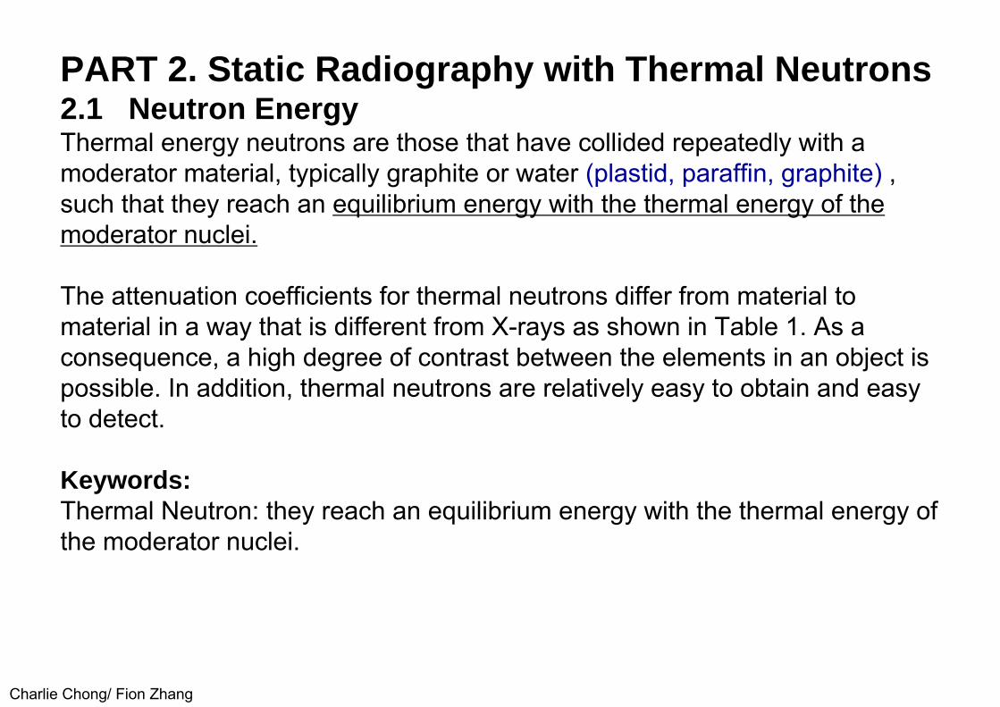
PART 2. Static Radiography with Thermal Neutrons2.1 Neutron EnergyThermal energy neutrons are those that have collided repeatedly with amoderator material, typically graphite or water (plastid, paraffin, graphite) , such that they reach an equilibrium energy with the thermal energy of the moderator nuclei.
The attenuation coefficients for thermal neutrons differ from material tomaterial in a way that is different from X-rays as shown in Table 1. As aconsequence, a high degree of contrast between the elements in an object ispossible. In addition, thermal neutrons are relatively easy to obtain and easy to detect.
Keywords:Thermal Neutron: they reach an equilibrium energy with the thermal energy of the moderator nuclei.

Charlie Chong/ Fion Zhang
TABLE 1. Comparison of X-ray and thermal neutron attenuation.
a. Other materials relatively transparent to thermal neutrons include gold,silver, platinum, titanium, silicon, tin and zinc.
b. Other materials relatively opaque to thermal neutrons include hydrogenousoils, plastics, rubbers, explosives and light elements boron and lithium.

Charlie Chong/ Fion Zhang
TABLE 6. Properties of Some Thermal Neutron Radiography Conversion Materials
promptprompt45 min42 s2.3 min24 sprompt54 min14 sprompt47 h9.2 hpromptprompt1.25 min140 min2.7 days
9103,830
111393591
20,00015742
41,000210
3,00061,000
254,0002,20080099
6Li(n,α) 3H10B(n,α) 7Li103Rh(n)104mRh103Rh(n)104Rh107Ag(n)108Ag109Ag (n)110 Ag113Cd((n,γ)114Cd115 In(n)116n115 In(n)116mln149Sm(n,γ) 150SmI52 Sm(n)153Sm151 Eu(n)152Eu155 Gd(n,γ) I56Gd157 Gd(n,γ)158Gd164 Dy(n)165mDy164 Dy(n)165Dy197 Au(n)198Au
LithiumBoronRhodium
Silver
CadmiumIndium
Samarium
EuropiumGadolinium
Dyprosium
Gold
LifeCross Section for Thermal Neutrons (barns)
Useful ReactionsMaterial

Charlie Chong/ Fion Zhang
2.2 Neutron CollimationBecause the source of thermal neutrons is a dispersed moderator volume,rather than a point source, it is necessary to use a collimator between thesource and the object.
In preference to a (1) single tube parallel sided collimator or a (2) multiple slit(channels) collimator, the most frequently used design uses (3) divergentbeam geometry.
The collimator may be used to extract a beam in any one of a variety of different geometries including horizontal or vertical, radial or tangential to the source.
A collimator that is tangential to the source can provide a thermal neutronbeam relatively free of fast neutron and gamma ray contamination.
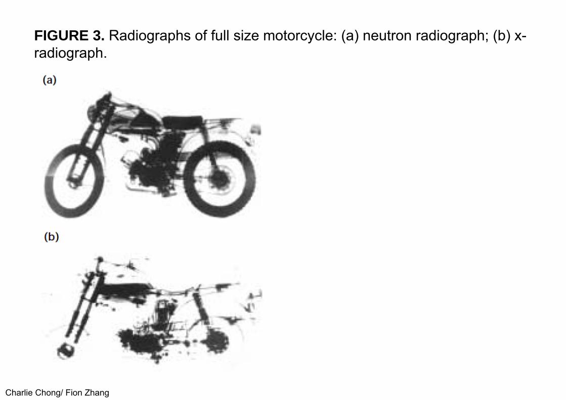
An incidental consequence of the divergent collimator principal is that even very large objects can be radiographed using an array of side-by-side films (Fig. 3).
Charlie Chong/ Fion Zhang
FIGURE 3. Radiographs of full size motorcycle: (a) neutron radiograph; (b) x-radiograph.

Charlie Chong/ Fion Zhang
The source of thermal neutrons is a dispersed moderator volume, ratherthan a point source
ASMV17 Neutron Radiography

Charlie Chong/ Fion Zhang ASMV17 Neutron Radiography
Charlie Chong/ Fion Zhang
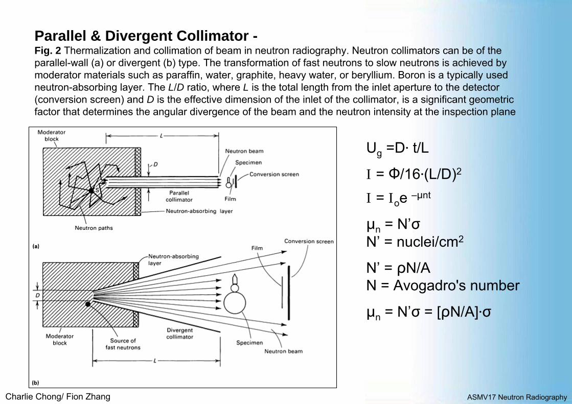
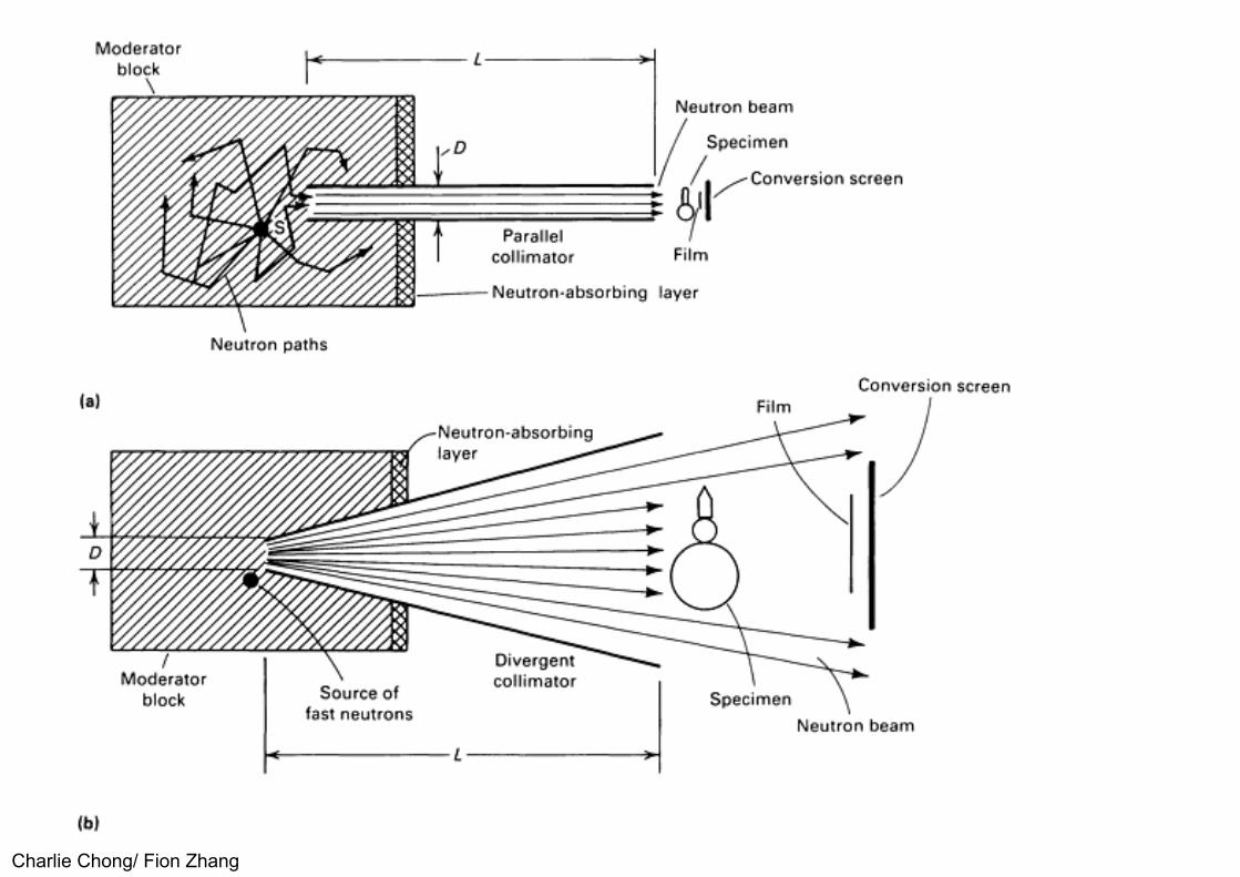
Parallel & Divergent Collimator -Fig. 2 Thermalization and collimation of beam in neutron radiography. Neutron collimators can be of theparallel-wall (a) or divergent (b) type. The transformation of fast neutrons to slow neutrons is achieved bymoderator materials such as paraffin, water, graphite, heavy water, or beryllium. Boron is a typically usedneutron-absorbing layer. The L/D ratio, where L is the total length from the inlet aperture to the detector(conversion screen) and D is the effective dimension of the inlet of the collimator, is a significant geometricfactor that determines the angular divergence of the beam and the neutron intensity at the inspection plane
ASMV17 Neutron Radiography
Ug =D∙ t/L
I = Ф/16∙(L/D)2
I = Ioe –μnt
μn = N’σN’ = nuclei/cm2
N’ = ρN/AN = Avogadro's number
μn = N’σ = [ρN/A]∙σ

Charlie Chong/ Fion Zhang
For photons:
I = Ioe –μx t Eq.1For Neutron
I = Ioe –Nσt = Ioe –μn t Eq.2
Where: I is the transmitted beam; Io is the incident beam; μx is the linear attenuation coefficient for photons; t is the thickness of specimen in the beam path;
N is the number of atoms per cubic centimeter; σ is the neutron cross section of the particular material or isotope
(a probability or effective area); and, μn is the linear attenuation coefficient for neutrons (μn = Nσ).
Charlie Chong/ Fion Zhang
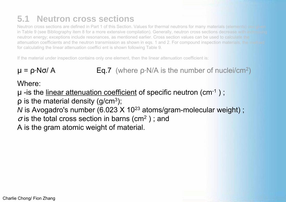
5.1 Neutron cross sectionsNeutron cross sections are defined in Part 1 of this Section. Values for thermal neutrons for many materials (elements) are given in Table 9 (see Bibliography item 8 for a more extensive compilation). Generally, neutron cross sections decrease with increasing neutron energy; exceptions include resonances, as mentioned earlier. Cross section values can be used to calculate the attenuation coefficients and the neutron transmission as shown in eqs. 1 and 2. For compound inspection materials, the method for calculating the linear attenuation coeffici ent is shown following Table 9.
If the material under inspection contains only one element, then the linear attenuation coefficient is:
μ = ρ∙Nσ/ A Eq.7 (where ρ∙N/A is the number of nuclei/cm2)
Where:μ -is the linear attenuation coefficient of specific neutron (cm-1 ) ;ρ is the material density (g/cm3); N is Avogadro's number (6.023 X 10²³ atoms/gram-molecular weight) ; σ is the total cross section in barns (cm2 ) ; and A is the gram atomic weight of material.
Charlie Chong/ Fion Zhang
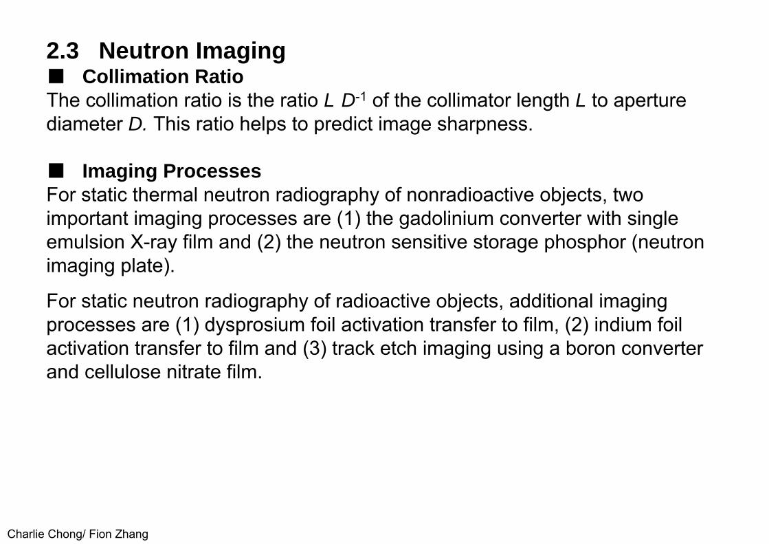
2.3 Neutron Imaging■ Collimation RatioThe collimation ratio is the ratio L·D-1 of the collimator length L to aperturediameter D. This ratio helps to predict image sharpness.
■ Imaging ProcessesFor static thermal neutron radiography of nonradioactive objects, twoimportant imaging processes are (1) the gadolinium converter with singleemulsion X-ray film and (2) the neutron sensitive storage phosphor (neutronimaging plate).
For static neutron radiography of radioactive objects, additional imaging processes are (1) dysprosium foil activation transfer to film, (2) indium foil activation transfer to film and (3) track etch imaging using a boron converter and cellulose nitrate film.
Charlie Chong/ Fion Zhang
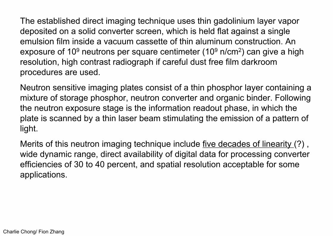
The established direct imaging technique uses thin gadolinium layer vapor deposited on a solid converter screen, which is held flat against a singleemulsion film inside a vacuum cassette of thin aluminum construction. An exposure of 109 neutrons per square centimeter (109 n/cm2) can give a high resolution, high contrast radiograph if careful dust free film darkroom procedures are used.
Neutron sensitive imaging plates consist of a thin phosphor layer containing a mixture of storage phosphor, neutron converter and organic binder. Following the neutron exposure stage is the information readout phase, in which the plate is scanned by a thin laser beam stimulating the emission of a pattern oflight.
Merits of this neutron imaging technique include five decades of linearity (?) ,wide dynamic range, direct availability of digital data for processing converterefficiencies of 30 to 40 percent, and spatial resolution acceptable for someapplications.

Charlie Chong/ Fion Zhang
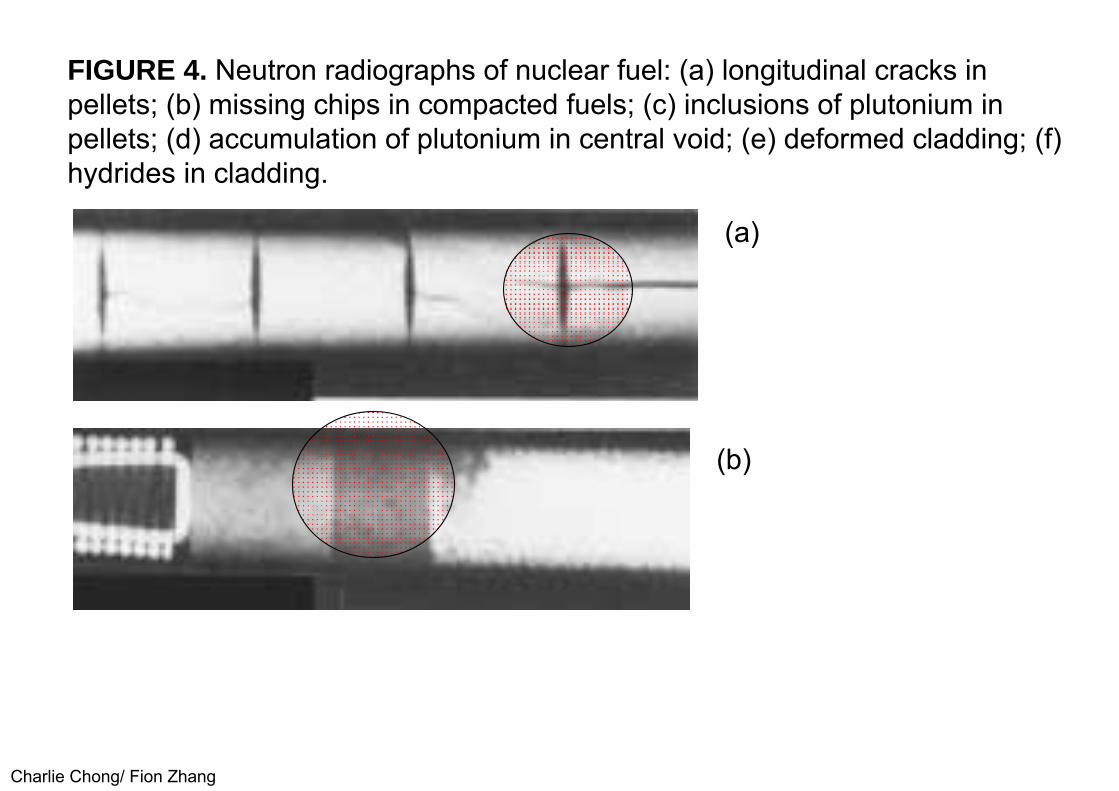
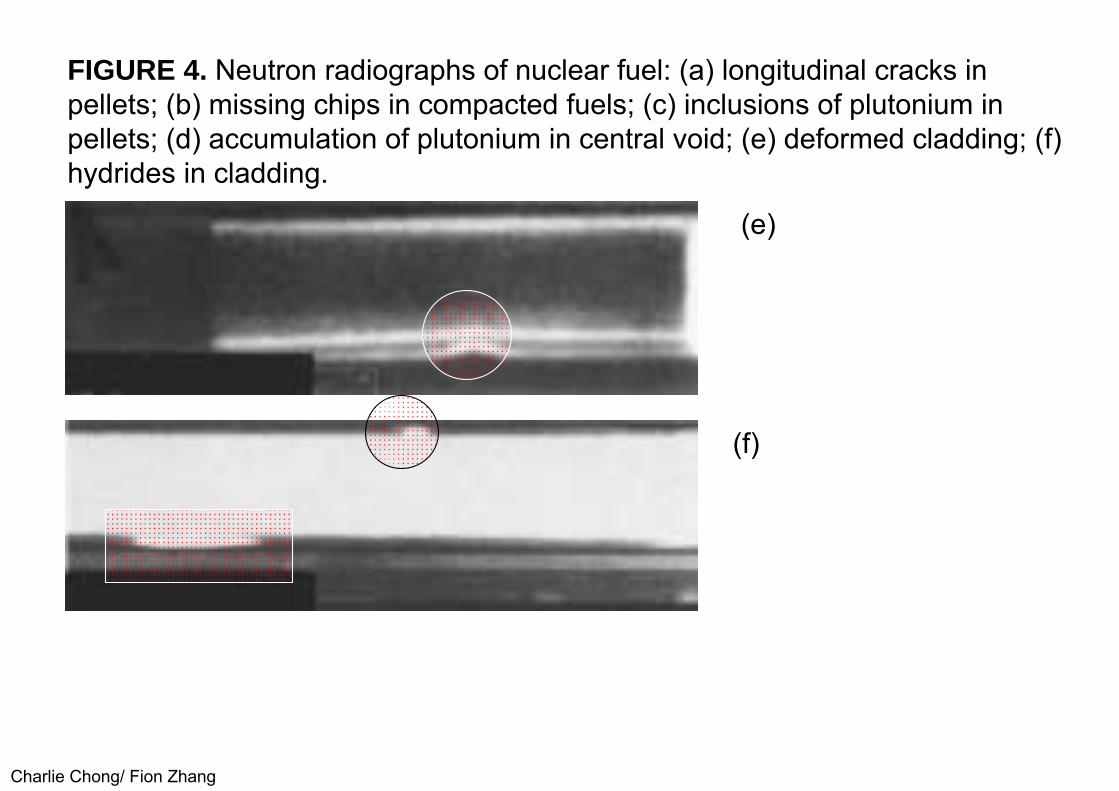
For neutron radiography of highly radioactive objects, dysprosium and indium foil activation transfer to film and track etch imaging each offer completediscrimination against gamma ray fogging. Examples of nuclear fuel neutron radiography are shown in Fig. 4. Dysprosium transfer can be combined with a cadmium indium foil sandwich for dual energy radiography. Alternative tracketch techniques have been developed to yield more precise dimensionalmeasurements.
Charlie Chong/ Fion Zhang
FIGURE 4. Neutron radiographs of nuclear fuel: (a) longitudinal cracks inpellets; (b) missing chips in compacted fuels; (c) inclusions of plutonium inpellets; (d) accumulation of plutonium in central void; (e) deformed cladding; (f)hydrides in cladding.
(a)
(b)

Charlie Chong/ Fion Zhang
FIGURE 4. Neutron radiographs of nuclear fuel: (a) longitudinal cracks inpellets; (b) missing chips in compacted fuels; (c) inclusions of plutonium inpellets; (d) accumulation of plutonium in central void; (e) deformed cladding; (f)hydrides in cladding.
(c)
(d)
Charlie Chong/ Fion Zhang
FIGURE 4. Neutron radiographs of nuclear fuel: (a) longitudinal cracks inpellets; (b) missing chips in compacted fuels; (c) inclusions of plutonium inpellets; (d) accumulation of plutonium in central void; (e) deformed cladding; (f)hydrides in cladding.
(e)
(f)
Charlie Chong/ Fion Zhang
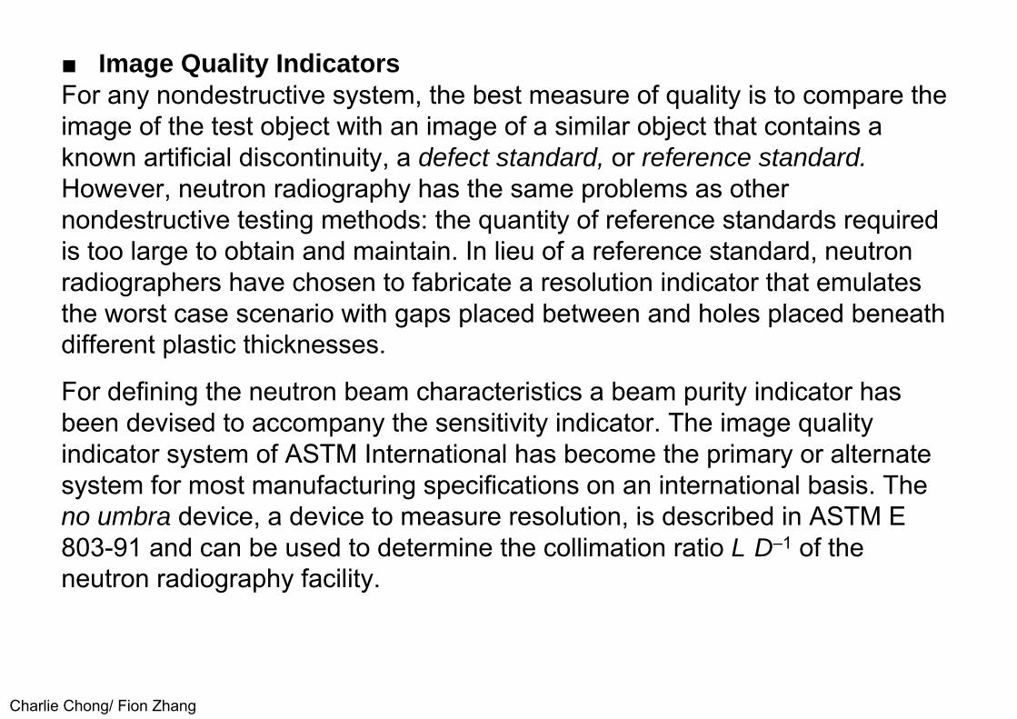
■ Image Quality IndicatorsFor any nondestructive system, the best measure of quality is to compare theimage of the test object with an image of a similar object that contains aknown artificial discontinuity, a defect standard, or reference standard.However, neutron radiography has the same problems as othernondestructive testing methods: the quantity of reference standards requiredis too large to obtain and maintain. In lieu of a reference standard, neutronradiographers have chosen to fabricate a resolution indicator that emulatesthe worst case scenario with gaps placed between and holes placed beneathdifferent plastic thicknesses.
For defining the neutron beam characteristics a beam purity indicator has been devised to accompany the sensitivity indicator. The image quality indicator system of ASTM International has become the primary or alternate system for most manufacturing specifications on an international basis. The no umbra device, a device to measure resolution, is described in ASTM E 803-91 and can be used to determine the collimation ratio L·D–1 of the neutron radiography facility.

Charlie Chong/ Fion Zhang
ASTM E803 - 91(2013) Standard Test Method for Determining the L/D Ratio of Neutron Radiography Beams
Charlie Chong/ Fion Zhang
Charlie Chong/ Fion Zhang
2.4 Nuclear Reactor SystemsA nuclear reactor system operated for over 30 years solely to provide acommercial neutron radiographic service is illustrated in Fig. 5. The reactorcore, positioned underground in a tank of water, is only about 0.38 m (15 in.)in diameter and operates at 250 kW power. The tangential beam tube isorientated vertically with air displaced by helium. Parts for neutronradiography can therefore be supported on horizontal trays. Usually theneutron imaging uses a gadolinium converter with fine grain radiographic filmand the exposure time at a selected collimation is typically about 2 min.

Charlie Chong/ Fion Zhang
FIGURE 5. Representative neutron radiographic service center fornonnuclear applications.

Charlie Chong/ Fion Zhang
Tangential Beam Tube
http://www-llb.cea.fr/spectros/spectro/2t1.html

Charlie Chong/ Fion Zhang
Another reactor that has provided neutron radiography services since 1968 isillustrated in Fig. 6. It is above ground and the fuel of the 100 kW core isarranged in an annulus with a moderator region in the center.
Two horizontal beams are extracted from the central moderator, one for direct film neutron radiography of nonradioactive objects, the other for dysprosium activation transfer neutron radiography of radioactive nuclear fuel.
Another service for static neutron radiography of radioactive nuclear fuel has been provided by a 250 kW nuclear reactor installed in a hot cell complex (Fig. 7). Also several university reactors in the United States have been equipped for neutron radiography. Worldwide, over fifty nuclear reactors have contributed to development of this field.

Charlie Chong/ Fion Zhang
FIGURE 6. Representative neutron radiographic service center for nuclear and nonnuclear applications.

Charlie Chong/ Fion Zhang
FIGURE 7. Hot cell fuel inspection system.

Charlie Chong/ Fion Zhang
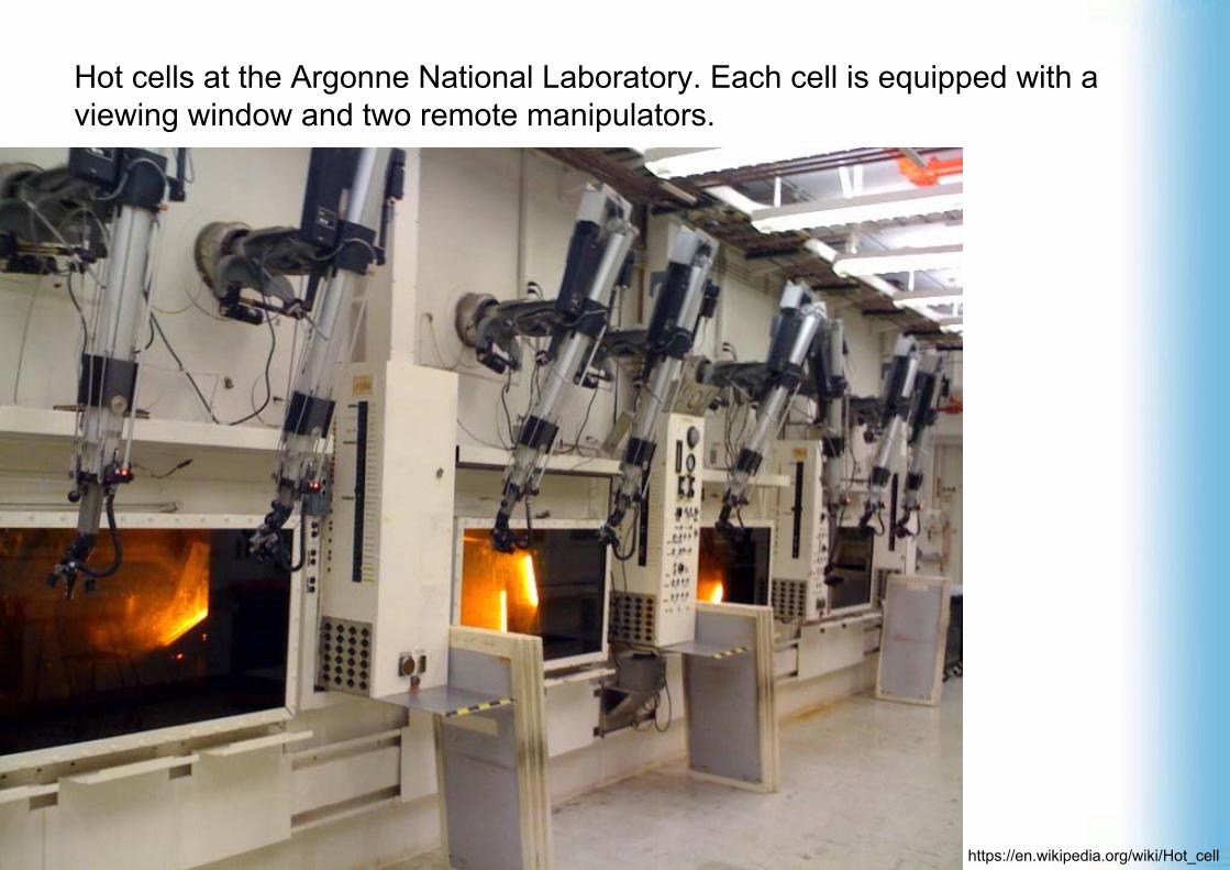
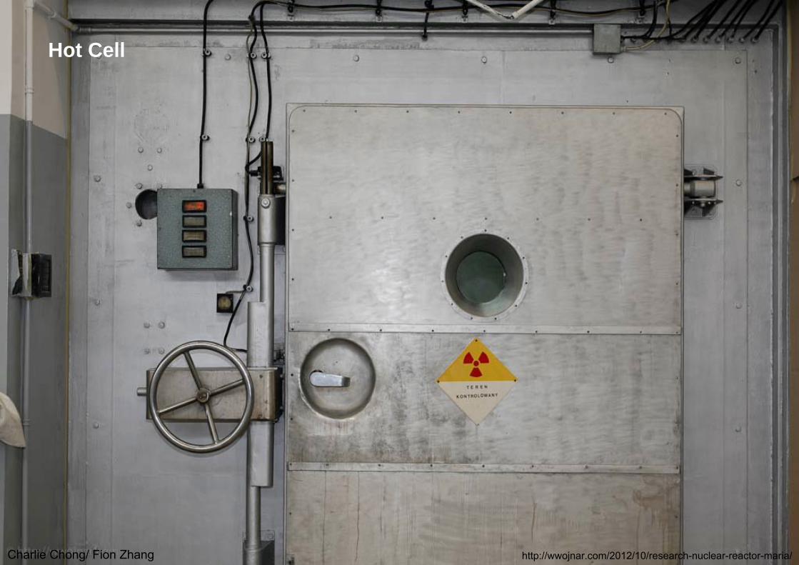
Hot cellShielded nuclear radiation containment chambers are commonly referred to as hot cells. The word "hot" refers to radioactivity. Hot cells are used in both the nuclear-energy and the nuclear-medicines industries. They are required to protect individuals from radioactive isotopes by providing a safe containment box in which they can control and manipulate the equipment required.

Charlie Chong/ Fion Zhang
Hot cellShielded nuclear radiation containment chambers are commonly referred to as hot cells. The word "hot" refers to radioactivity. Hot cells are used in both the nuclear-energy and the nuclear-medicines industries. They are required to protect individuals from radioactive isotopes by providing a safe containment box in which they can control and manipulate the equipment required.
https://en.wikipedia.org/wiki/Hot_cell
Charlie Chong/ Fion Zhang
Hot cells at the Argonne National Laboratory. Each cell is equipped with a viewing window and two remote manipulators.
https://en.wikipedia.org/wiki/Hot_cell
Charlie Chong/ Fion Zhang
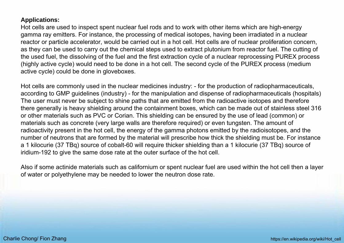
Applications:Hot cells are used to inspect spent nuclear fuel rods and to work with other items which are high-energy gamma ray emitters. For instance, the processing of medical isotopes, having been irradiated in a nuclear reactor or particle accelerator, would be carried out in a hot cell. Hot cells are of nuclear proliferation concern, as they can be used to carry out the chemical steps used to extract plutonium from reactor fuel. The cutting of the used fuel, the dissolving of the fuel and the first extraction cycle of a nuclear reprocessing PUREX process (highly active cycle) would need to be done in a hot cell. The second cycle of the PUREX process (medium active cycle) could be done in gloveboxes.
Hot cells are commonly used in the nuclear medicines industry: - for the production of radiopharmaceuticals, according to GMP guidelines (industry) - for the manipulation and dispense of radiopharmaceuticals (hospitals) The user must never be subject to shine paths that are emitted from the radioactive isotopes and therefore there generally is heavy shielding around the containment boxes, which can be made out of stainless steel 316 or other materials such as PVC or Corian. This shielding can be ensured by the use of lead (common) or materials such as concrete (very large walls are therefore required) or even tungsten. The amount of radioactivity present in the hot cell, the energy of the gamma photons emitted by the radioisotopes, and the number of neutrons that are formed by the material will prescribe how thick the shielding must be. For instance a 1 kilocurie (37 TBq) source of cobalt-60 will require thicker shielding than a 1 kilocurie (37 TBq) source of iridium-192 to give the same dose rate at the outer surface of the hot cell.
Also if some actinide materials such as californium or spent nuclear fuel are used within the hot cell then a layer of water or polyethylene may be needed to lower the neutron dose rate.
https://en.wikipedia.org/wiki/Hot_cell
Charlie Chong/ Fion Zhang
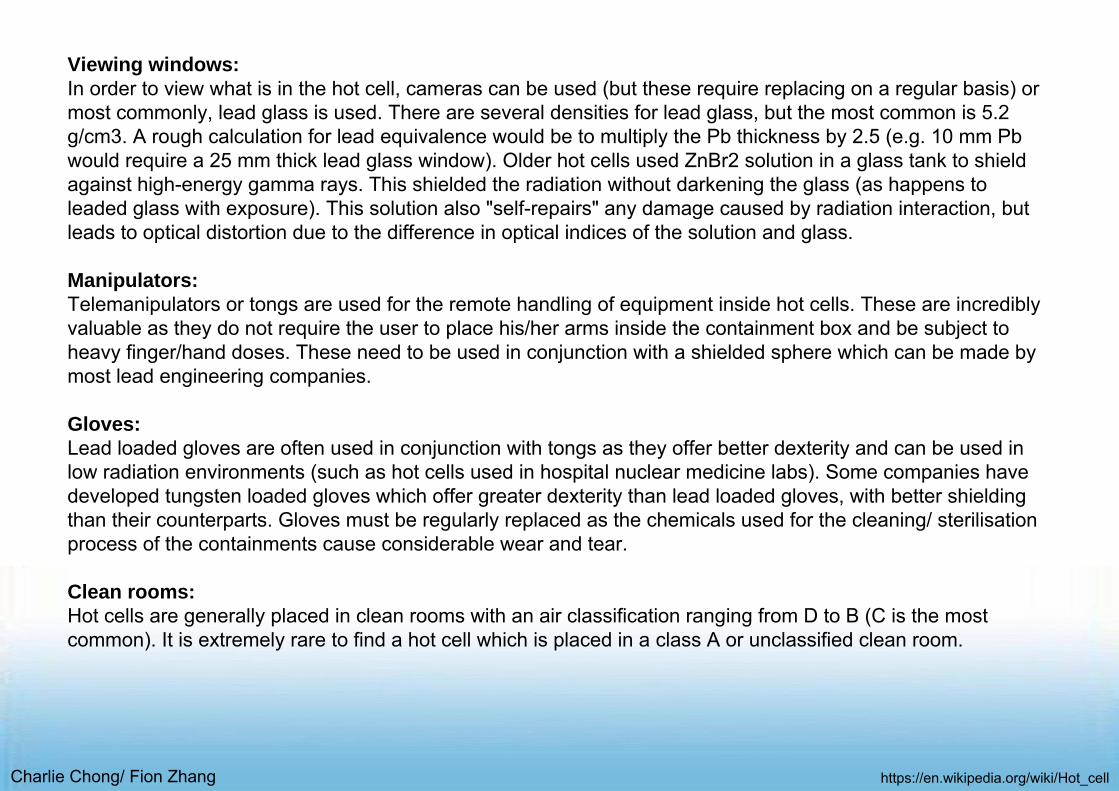
Viewing windows:In order to view what is in the hot cell, cameras can be used (but these require replacing on a regular basis) or most commonly, lead glass is used. There are several densities for lead glass, but the most common is 5.2 g/cm3. A rough calculation for lead equivalence would be to multiply the Pb thickness by 2.5 (e.g. 10 mm Pbwould require a 25 mm thick lead glass window). Older hot cells used ZnBr2 solution in a glass tank to shield against high-energy gamma rays. This shielded the radiation without darkening the glass (as happens to leaded glass with exposure). This solution also "self-repairs" any damage caused by radiation interaction, but leads to optical distortion due to the difference in optical indices of the solution and glass.
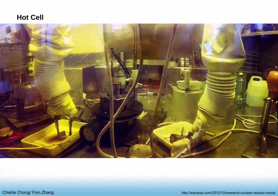
Manipulators:Telemanipulators or tongs are used for the remote handling of equipment inside hot cells. These are incredibly valuable as they do not require the user to place his/her arms inside the containment box and be subject to heavy finger/hand doses. These need to be used in conjunction with a shielded sphere which can be made by most lead engineering companies.
Gloves:Lead loaded gloves are often used in conjunction with tongs as they offer better dexterity and can be used in low radiation environments (such as hot cells used in hospital nuclear medicine labs). Some companies have developed tungsten loaded gloves which offer greater dexterity than lead loaded gloves, with better shielding than their counterparts. Gloves must be regularly replaced as the chemicals used for the cleaning/ sterilisationprocess of the containments cause considerable wear and tear.
Clean rooms:Hot cells are generally placed in clean rooms with an air classification ranging from D to B (C is the most common). It is extremely rare to find a hot cell which is placed in a class A or unclassified clean room.
https://en.wikipedia.org/wiki/Hot_cell
Charlie Chong/ Fion Zhang
Hot Cell
http://wwojnar.com/2012/10/research-nuclear-reactor-maria/

Charlie C
hong/ Fion Zhang
Hot Cell
http://ww
ojnar.com/2012/10/research-nuclear-reactor-m
aria/
Charlie Chong/ Fion Zhang
Hot Cell
http://wwojnar.com/2012/10/research-nuclear-reactor-maria/

Charlie C
hong/ Fion Zhang http://w
wojnar.com
/2012/10/research-nuclear-reactor-maria/
Hot Cell

Charlie Chong/ Fion Zhang http://wwojnar.com/2012/10/research-nuclear-reactor-maria/
Hot Cell

Charlie C
hong/ Fion Zhang
Hot C
ell
http://ww
ojnar.com/2012/10/research-nuclear-reactor-m
aria/
Hot Cell

Charlie Chong/ Fion Zhang http://wwojnar.com/2012/10/research-nuclear-reactor-maria/
Hot Cell

Charlie Chong/ Fion Zhang
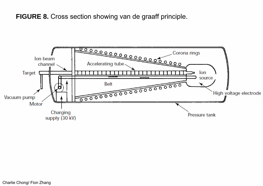
2.5 Accelerator Based SystemsAn initial user of neutron radiography need not, in general, be concerned withaccelerator source options unless there is an established need either for anin-house system or for a transportable system. Almost all neutron radiographyservice providers use a nuclear reactor source. One exception has been thepowerful spallation type accelerator in Switzerland; the accelerator is amultipurpose facility comparable in complexity and cost to a research reactor.An in-house system that was operated successfully for over 15 years at theUnited States Department of Energy’s Pantex Plant used a van de graaffaccelerator. The operation of this machine, which accelerates over 200 μA ofdeuterons at 3 MeV into a beryllium target, is illustrated in Fig. 8.
Charlie Chong/ Fion Zhang
FIGURE 8. Cross section showing van de graaff principle.

Charlie Chong/ Fion Zhang
The system provided a peak thermal neutron flux of about 109 neutrons per square centimeter second (109 n∙cm-1∙s-1), two orders of magnitude less thanthe reactor systems described above but sufficient for low throughput work using 2 h exposure times and a relatively low beam collimation ratio.
Cyclotrons and radio frequency quadrupole accelerators are other candidates for a potential custom designed in-house neutron radiographic system. Neutron radiographic performance data have been reported for designs with a variety of sizes, neutron yields and costs. For transportable systems much of the development work has used sealed tube acceleration of deuterium tritiummixtures. This can consist of a source head that is maneuverable with longhigh tension cable linking it to the high voltage power supply and control unitas illustrated (Fig. 9). The particular type shown yields a peak thermal neutronflux of about 108 neutrons per square centimeter second with a tube operationhalf life of about 200 h.

Charlie Chong/ Fion Zhang
FIGURE 9. Components of mobile deuterium tritium neutron radiographic system: (a) deuterium tritium source head, typically on 6 m (20 ft) cables; (b)cooling unit (left) and power supply; (c) control unit.

Charlie Chong/ Fion Zhang
2.6 High Intensity Californium-252 SystemsOf the many radioactive neutron sources, such as polonium-210, berylliumand americium-244 beryllium, one has dominated interest for neutronradiography: californium-252. This transplutonic isotope is produced as abyproduct of basic research programs. In the United States, somegovernment centers have been able to obtain the source on a low cost loanbasis from the Department of Energy. The isotope yields neutrons byspontaneous fission at a rate of 2 × 10⁹ neutrons per second per milligramand has a half life of 2.5 years. A high yield source of up to 50 mg can besmaller than a tube of lipstick (Fig. 10). An in-house stationary system hasoperated at the United States Department of Energy’s installation at Pantexwith a total source strength of 150 mg californium-252. It provided sets of ninefilms, each 350 × 425 mm (14 × 17 in.), approaching reactor quality by using gadolinium with a very fine grain X-ray film; a collimator ratio of 65; andexposure time of under 24 h.

Charlie Chong/ Fion Zhang
FIGURE 10. Californium-252 sources compared in size to postage stamp.

Charlie Chong/ Fion Zhang
A maneuverable source system has operated at McClellan Air Force Base with a total source strength of 50 mg californium- 52. It provided singleneutron radiographs using a fast scintillator screen; high speed, light sensitive film; a collimator ratio of 30; and an exposure time of 12 min. This system was designed for the specific application of scanning intact aircraft to detect hidden problems at an early stage, such as moisture or corrosion in aluminum honeycomb.26 Another example of a high yield californium-252 system design uses a subcritical multiplier to amplify the central neutron flux. This design (Fig. 11) produces a peak central flux of 7 × 10⁸ neutrons per square centimeter second when loaded with 40 mg californium-252.

Charlie Chong/ Fion Zhang
FIGURE 11. Elevation of subcritical multiplier system.

Charlie Chong/ Fion Zhang
■ Low Cost In-House SystemThere is evidence that an extremely low intensity californium-252 neutronsource could provide a convenient, low cost in-house system. A source sizeof only 100 μg can provide useful quality neutron radiographs by using highlyefficient imaging systems that need only 105 neutrons per square centimeterexposure. This is 10 000 times less than the exposure used typically withgadolinium and single emulsion film. The small source size would mean aninexpensive source and also inexpensive shielding, handling and interlockrequirements. Therefore, a nondestructive testing center with a variety of X-ray, ultrasonic and other inspection capabilities could easily incorporate asmall californium-252 based neutron radiographic capability using anunderground storage geometry in an existing radiographic bay. Becauseneutron radiography yields unique information, such an inexpensive in-housecapability could be an important complement to an otherwise full servicenondestructive testing center.

Charlie Chong/ Fion Zhang
Californium-252 Neutron Source
http://www.orau.org/ptp/collection/Sources/cf-252.htm
Charlie Chong/ Fion Zhang
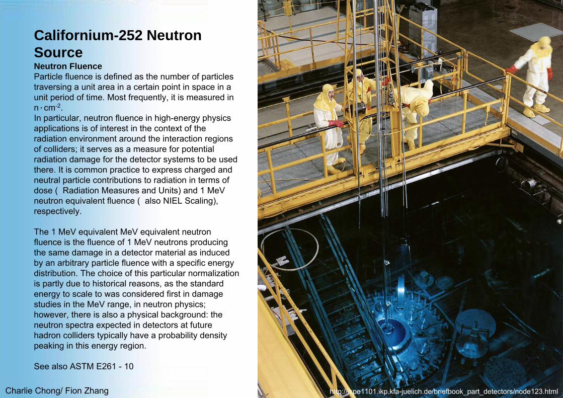
Californium-252 NeutronSourceNeutron FluenceParticle fluence is defined as the number of particles traversing a unit area in a certain point in space in a unit period of time. Most frequently, it is measured in n∙cm-2. In particular, neutron fluence in high-energy physics applications is of interest in the context of the radiation environment around the interaction regions of colliders; it serves as a measure for potential radiation damage for the detector systems to be used there. It is common practice to express charged and neutral particle contributions to radiation in terms of dose ( Radiation Measures and Units) and 1 MeVneutron equivalent fluence ( also NIEL Scaling), respectively.
The 1 MeV equivalent MeV equivalent neutron fluence is the fluence of 1 MeV neutrons producing the same damage in a detector material as induced by an arbitrary particle fluence with a specific energy distribution. The choice of this particular normalization is partly due to historical reasons, as the standard energy to scale to was considered first in damage studies in the MeV range, in neutron physics; however, there is also a physical background: the neutron spectra expected in detectors at future hadron colliders typically have a probability density peaking in this energy region.
See also ASTM E261 - 10
http://ikpe1101.ikp.kfa-juelich.de/briefbook_part_detectors/node123.html

Charlie Chong/ Fion Zhang
PART 3. Special Techniques of NeutronRadiography3.1 Dynamic Neutron RadioscopyServices that provide different types of dynamic neutron radioscopy havebeen developed at numerous nuclear reactor centers worldwide. They coverframe rates that range from 30 frames per second (real time motion displaysimilar to television) to 1000 frames per second range (a high frame rate) orto 10 000 frames per second (a very high frame rate). An example of a real time dynamic neutron radioscopic application is illustrated in Figure 12. Abeam from a 28 MW reactor was used to study the flow characteristics oflubricant inside an operating jet engine. Other applications have includedstudies of absorption and compression refrigerator designs, studies ofautomotive parts in motion and a large range of two-phase flow studies. Forhigh throughput dynamic neutron imaging one reactor center has beenequipped with three separate beams, each with its neutron imaging systemand digital image interpretation system.

Charlie Chong/ Fion Zhang
FIGURE 12. Frames from real time studies of operating aircraft engine: (a) first view; (b) second view.
Charlie Chong/ Fion Zhang
Other reactor centers have developed techniques for simultaneous neutron and gamma ray dynamic imaging using a pair of scintillator screens in conjunction with a low light level television camera and video processing. The development of dynamic neutron radioscopic services with a high frame rateof 1000 frames per second has capitalized on the availability of very high intensity steady state neutron beams (with a flux of 108 neutrons per square centimeter second) and very high frame rate video cameras used with rapid response neutron sensitive scintillator screens. A very high frame rate capability, up to 10 000 frames per second, uses the ability of certain reactors to be pulsed, giving a high neutron yield for a time duration of a fewmilliseconds. The event to be studied, such as the burn cycle of a pyrotechnicevent 爆破效果, is synchronized to the neutron pulse time.
Charlie Chong/ Fion Zhang
3.2 Subthermal Neutron Radiology (Cold)The neutron attenuation coefficient of a particular material can changesignificantly as the neutron energy is changed. The pattern of this variationalso changes abruptly from one element to another. Therefore, selection ofdifferent energy neutrons provides possibilities for quite different neutronradiology penetration and contrast. Neutron radiology service reactors havedeveloped neutron beams of selected subthermal or cold neutrons usingthree techniques:
(1) beam filtration by polycrystal beryllium, which passes only long wavelength, low energy neutrons below 0.005 eV,
(2) a refrigerated moderator volume and (3) selection of longer wavelength, low energy neutrons by multiple internal
reflection in a gently curved guide tube.
Keypoints:Beam filter, Beryllium pass only cold neutron.Cadmium remove thermal & cold neutrons and pass epithermal neutrons.Polycrystal beryllium pass only low energy neutrons.

Charlie Chong/ Fion Zhang

Charlie Chong/ Fion Zhang
The effect of this energy selection is typically to increase the transparency ofcertain materials while simultaneously increasing the contrast or detectabilityof hydrogenous materials (see Table 2 and Fig. 13). Just as thermal neutronradiography gives different information to X-radiography, so subthermal orcold neutron radiography gives information different from that of regularthermal neutron techniques. An example is given in Fig. 14. It is possible,using a guide tube, to select only very cold neutrons (that is, energies below0.001 eV) and this can provide high sensitivity for very thin hydrogenousspecimens.
Charlie Chong/ Fion Zhang
TABLE 2. Relative neutron attenuation coefficients.
Charlie Chong/ Fion Zhang
FIGURE 13. Attenuation of materials for thermal and cold neutrons.
Charlie Chong/ Fion Zhang
FIGURE 14. Neutron radiographs of explosive bridge wire igniter: (a) thermalneutron image; (b) cold neutron image.
Explosive charge

Charlie Chong/ Fion Zhang
3.3 Epithermal and Fast Neutron RadiologyA reactor beam, although consisting primarily of thermal neutrons, will containa proportion of both subthermal and epithermal (high energy) neutrons. Witha filter such as cadmium, the thermal and subthermal neutrons can beremoved and only the epithermal part of the neutron energy spectrum will betransmitted. For the inspection of enriched nuclear fuel the higher penetration of epithermal neutrons provides a valuable difference from thermal or subthermal neutron radiography. Indium has a high resonance capture cross section at about 1.4 eV epithermal energy. Cadmium wrapped indium foil activation transfer imaging techniques have been used for this application.Another epithermal neutron technique uses an indium foil filter in the incidentbeam to remove neutrons close to the specific resonance energy. This beam is passed through the object and an indium detector is used on the far side.
Keypoints:Beam filter, Beryllium pass only cold neutron.Cadmium remove thermal & cold neutrons and pass epithermal neutrons.
Charlie Chong/ Fion Zhang
The technique can provide high sensitivity to small quantities of hydrogen in the object because hydrogen can change the energy of an incident neutron more than heavier elements. The term fast neutron radiography refers normally to those neutron energies yielded by an unmoderated acceleratorsource or radioactive source. Fast neutron radiography provides high penetration but little contrast between elements. The accelerator can provide a point source. Tantalum is one of several detector materials for direct exposure and scintillator screens can be used. Alternatively, foil activation transfer with holmium has been demonstrated.
Keypoints:Beam filter, Beryllium pass only cold neutron.Cadmium remove thermal & cold neutrons and pass epithermal neutrons.Fast neutron direct radiography: Tantalum Fast neutron transfer radiography; Holmium

Charlie Chong/ Fion Zhang
3.4 Neutron Computed TomographyComputed axial tomography has been developed for neutron radiography andcan provide detailed cross sectional slices of the object to be analyzed.Although the principle is similar to that of X-ray computed tomography, theinformation conveyed by neutrons can be unique. In a typical facility theobject is rotated in the neutron beam and data are stored for upward of 200angles. Detectors used have included a scintillator screen 6LiF-ZnS (Ag),viewed by a cooled charge coupled device camera and alternatively a storagephosphor image plate loaded with Gd2O3 combined with an automatic laserbeam scanner. Using a high intensity neutron radiography beam of over 108
neutrons per square centimeter second, computed tomography of two-phaseflow volumes has been processed as a time averaged three-dimensionalanalysis.

Charlie Chong/ Fion Zhang
3.5 Neutron Gaging and Neutron Probe TechniquesNeutron gaging is the measurement of attenuation of a collimated smalldiameter beam of radiation as it is transmitted by a specimen. A neutronradiology service center equipped with a nuclear reactor has demonstratedthat the imaging techniques can be complemented by the more quantitativetechniques of gaging. The gaging technique can inspect items of greater thickness than can be inspected with neutron radiography. It has been used for static gaging of discrete assemblies and for continuous scanning of long objects for acceptable uniformity. There are also a variety of neutron probe techniques in which radiation, typically gamma, is observed as a result ofneutron radiation incident on the object. For example the associated particle sealed tube neutron generator enables the flight time of the incident neutron to be used in conjunction with gamma ray spectroscopy to indicate the chemical composition within an object. This technique has been developed for identification of hidden explosives, drugs or nuclear materials. Another example of a neutron probe is neutron interferometry to detect phase shifts of the neutron wave properties. This neutron phase topography has beenproposed for very high sensitivity material testing.

Charlie Chong/ Fion Zhang
■ Neutron Induced AutoradiographyBy exposing a painting to thermal or cold neutrons and later imaging theradioactivity induced in the various paint components, a technique has beendeveloped sensitive to many elements including manganese, potassium,copper, sodium, arsenic, phosphorus, gold, iron, mercury, antimony andcobalt. The neutron exposures were originally performed in a moderator block(thermal column), close to a reactor core. However, beams similar to thoseused for transmission neutron radiography have been used for this neutroninduced autoradiography of paintings. Typically, a series of autoradiographs is taken using a range of neutron exposure times and different decay times before imaging. This, combined with a range of scintillator screen and film sensitivities, can provide extensive information about successive layers of each painting.
Charlie Chong/ Fion Zhang
3.6 ClosingIndustry standards have been published on neutron radiographic testing.

Charlie Chong/ Fion Zhang
End Of Reading 1

Charlie Chong/ Fion Zhang
Reading-2Assorted Readings
Charlie Chong/ Fion Zhang
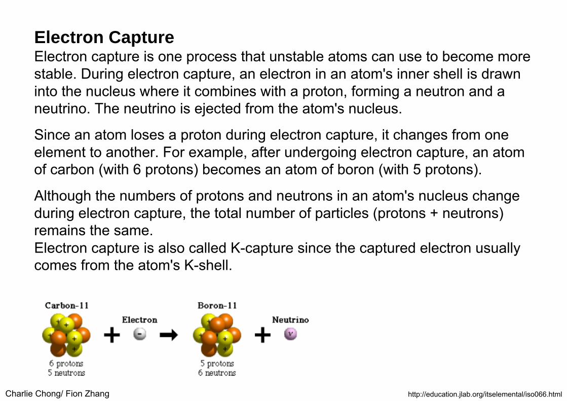
Electron CaptureElectron capture is one process that unstable atoms can use to become more stable. During electron capture, an electron in an atom's inner shell is drawn into the nucleus where it combines with a proton, forming a neutron and a neutrino. The neutrino is ejected from the atom's nucleus.
Since an atom loses a proton during electron capture, it changes from one element to another. For example, after undergoing electron capture, an atom of carbon (with 6 protons) becomes an atom of boron (with 5 protons).
Although the numbers of protons and neutrons in an atom's nucleus change during electron capture, the total number of particles (protons + neutrons) remains the same.Electron capture is also called K-capture since the captured electron usually comes from the atom's K-shell.
http://education.jlab.org/itselemental/iso066.html
Charlie Chong/ Fion Zhang
Beta DecayBeta decay results in the emission of an electron and antineutrino, or a positron and neutrino.
Beta decay is one process that unstable atoms can use to become more stable. There are two types of beta decay, beta-minus and beta-plus.During beta-minus decay, a neutron in an atom's nucleus turns into a proton,an electron and an antineutrino.
The electron and antineutrino fly away from the nucleus, which now has one more proton than it started with. Since an atom gains a proton during beta-minus decay, it changes from one element to another. For example, after undergoing beta-minus decay, an atom of carbon (with 6 protons) becomes an atom of nitrogen (with 7 protons).
During beta-plus decay, a proton in an atom's nucleus turns into a neutron, a positron and a neutrino.
http://education.jlab.org/itselemental/iso066.html

Charlie Chong/ Fion Zhang http://education.jlab.org/itselemental/iso066.html
The positron and neutrino fly away from the nucleus, which now has one less proton than it started with. Since an atom loses a proton during beta-plus decay, it changes from one element to another. For example, after undergoing beta-plus decay, an atom of carbon (with 6 protons) becomes an atom of boron (with 5 protons).Although the numbers of protons and neutrons in an atom's nucleus change during beta decay, the total number of particles (protons + neutrons) remains the same.

Charlie Chong/ Fion Zhang
Proton EmissionAfter proton emission, an atom contains one less proton.Proton emission is one process that unstable atoms can use to become more stable. During proton emission, a proton is ejected from an atom's nucleus.Since an atom loses a proton during proton emission, it changes from one element to another. For example, after undergoing proton emission, an atom of nitrogen (with 7 protons) becomes an atom of carbon (with 6 protons).
http://education.jlab.org/itselemental/iso066.html

Charlie Chong/ Fion Zhang
Alpha DecayAlpha decay is one process that unstable atoms can use to become more stable. During alpha decay, an atom's nucleus sheds two protons and two neutrons in a packet that scientists call an alpha particle.
Since an atom loses two protons during alpha decay, it changes from one element to another. For example, after undergoing alpha decay, an atom of uranium (with 92 protons) becomes an atom of thorium (with 90 protons).
http://education.jlab.org/itselemental/iso066.html

Charlie Chong/ Fion Zhang
Neutron RadiographyNeutron Radiography is a non-destructive imaging technique utilizing thermal neutrons. Classically, it has been used for quality control purposes in industries which require precision machining such as aircraft engines. Today, the most important application of neutron radiography is in testing the performance of fuel cells by imaging water flow in the cells in situ. Neutron radiography has also been used in the art world and in archeology to authenticate paintings and examine artifacts made of metal or stone. Neutrons have many advantages for imaging over visible light, x-rays or electrons. The advantages include greater penetration depth into most materials, considerable variations in contrast between chemical elements and isotopes, and weaker radiation damage than other penetrating radiation. MIT Reactor has two facilities suitable for neutron imaging projects for both scientific and industrial applications. One facility provides a thermal neutron beam with L/D ratio of up to 1000 when the beam is of 2” diameter. Another facility provides a vertical beam of 10” diameter, with smaller L/D.
http://web.mit.edu/nrl/www/research/radiography.htm

Charlie Chong/ Fion Zhang
An image of ASTM standard samples, plastic screw (thread period of 1 mm) and Gd plate with 1 mm pin-hole aperture. The ASTM standard in the center left is made of Teflon with 2 boron-nitride disks, 2 cadmium wires and two lead disks (invisible). The standard sample on the center right is made of plastic of various thickness separated by aluminum blades of different width. Spatial resolution is better than 500 micron in this low L/D setup. Contamination with gamma-radiation is very low.
In addition to research possibilities in advanced materials, the neutron imaging facility is an excellent teaching tool for MIT students and faculty in imaging.
http://web.mit.edu/nrl/www/research/radiography.htm
Charlie Chong/ Fion Zhang
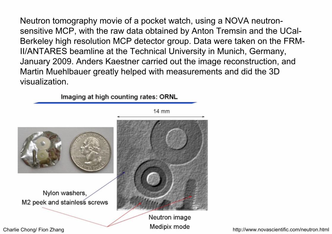
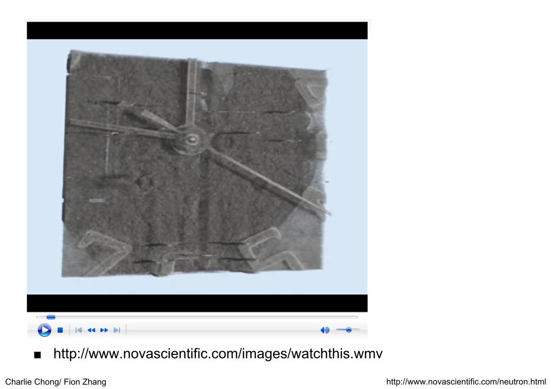
Neutron tomography movie of a pocket watch, using a NOVA neutron-sensitive MCP, with the raw data obtained by Anton Tremsin and the UCal-Berkeley high resolution MCP detector group. Data were taken on the FRM-II/ANTARES beamline at the Technical University in Munich, Germany, January 2009. Anders Kaestner carried out the image reconstruction, and Martin Muehlbauer greatly helped with measurements and did the 3D visualization.
http://www.novascientific.com/neutron.html
Charlie Chong/ Fion Zhang
■ http://www.novascientific.com/images/watchthis.wmv
http://www.novascientific.com/neutron.html
Charlie Chong/ Fion Zhang http://www.novascientific.com/neutron.html

Charlie Chong/ Fion Zhang
Huge contrast range: Loudspeaker with steel casing on cardboard box, plant seeds and grass, tape

Charlie Chong/ Fion Zhang
Computer hard disk (cutout of big image)
Charlie Chong/ Fion Zhang
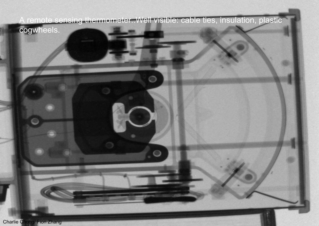
A remote sensing thermometer..Well visible: cable ties, insulation, plastic cogwheels.
Charlie Chong/ Fion Zhang
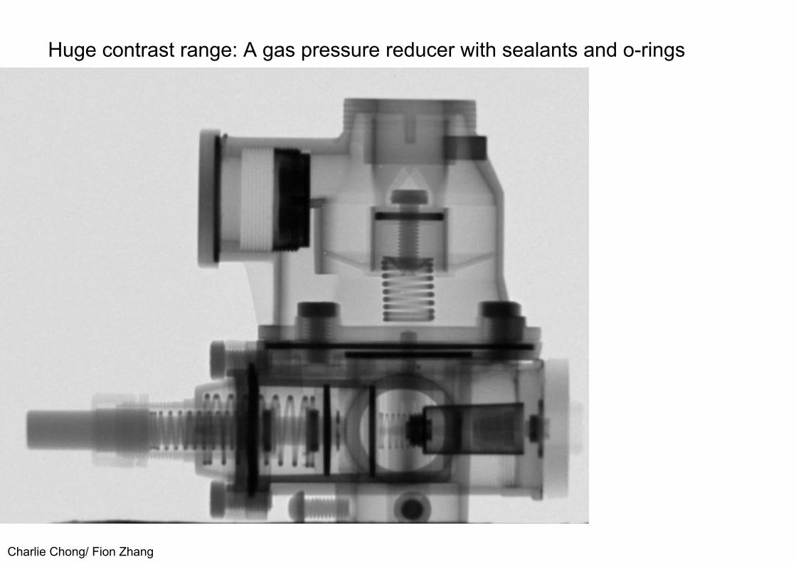
Huge contrast range: A gas pressure reducer with sealants and o-rings

Charlie Chong/ Fion Zhang
But on this oil-filled pump, thermal neutrons must fail….
Charlie Chong/ Fion Zhang
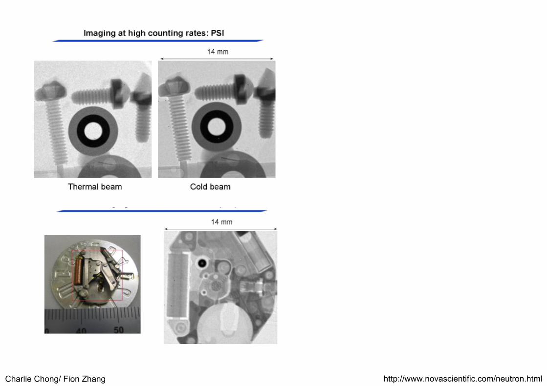
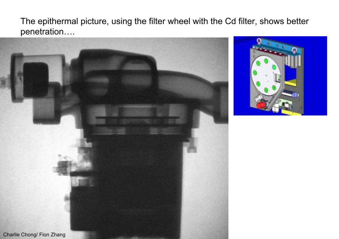
The epithermal picture, using the filter wheel with the Cd filter, shows better penetration….
Charlie Chong/ Fion Zhang
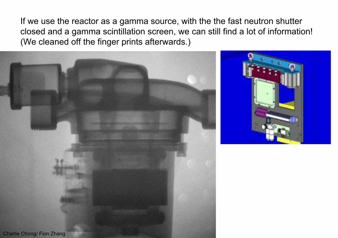
If we use the reactor as a gamma source, with the the fast neutron shutter closed and a gamma scintillation screen, we can still find a lot of information!(We cleaned off the finger prints afterwards.)
Charlie Chong/ Fion Zhang
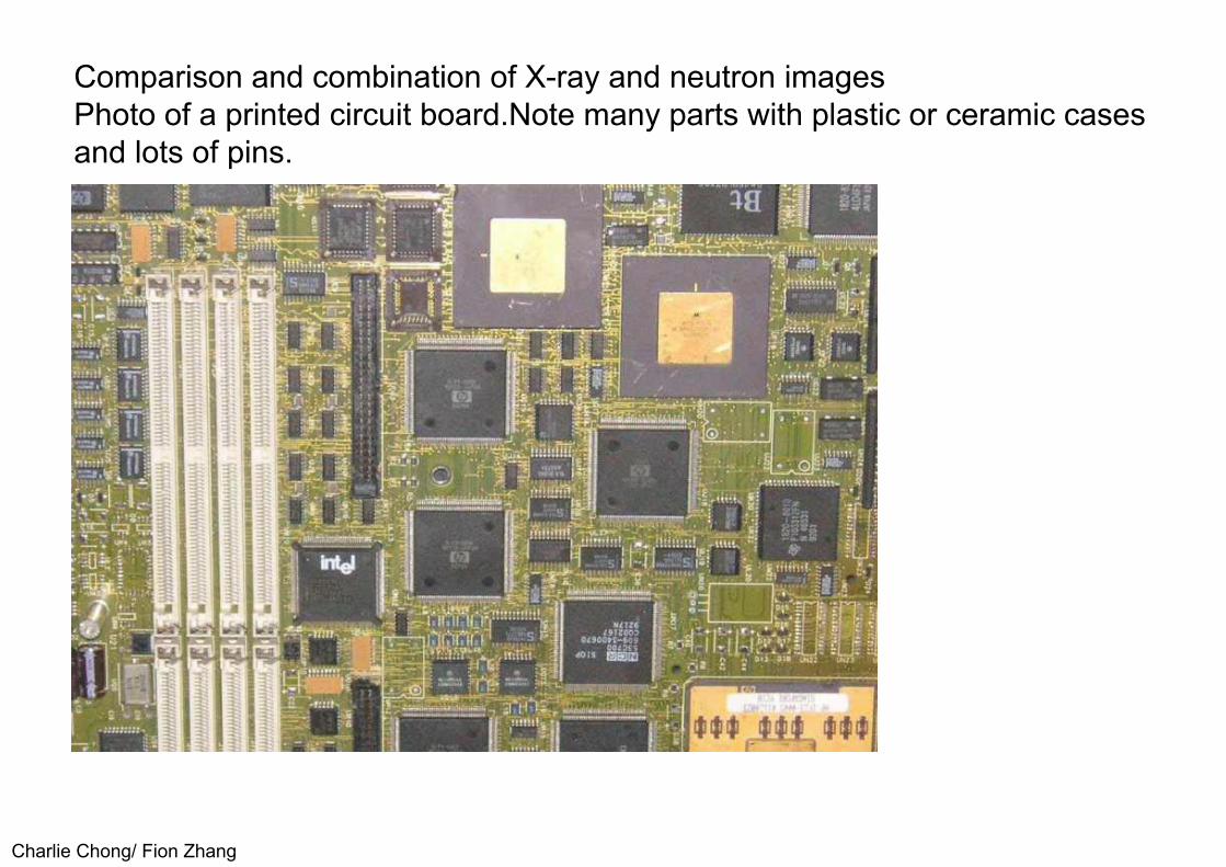
Comparison and combination of X-ray and neutron imagesPhoto of a printed circuit board.Note many parts with plastic or ceramic cases and lots of pins.

Charlie Chong/ Fion Zhang
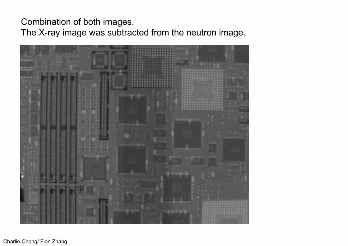
X-ray image.Most contrast is given by the metal pins.

Charlie Chong/ Fion Zhang
Neutron image.Most contrast is given by plastic parts, the metal pins are nearly transparent.
Charlie Chong/ Fion Zhang
Combination of both images.The X-ray image was subtracted from the neutron image.

Charlie Chong/ Fion Zhang
A toy plane combustion engine with a plastic propeller isanother good example for the different properties of X-rays and neutrons.

Charlie Chong/ Fion Zhang
The X-rays easily penetrate the plastic propeller, still penetrate the Aluminium well, but are heavily attenuated by steel parts.

Charlie Chong/ Fion Zhang
Aluminium is very transparent for neutrons, steel is better penetratedthan by X-rays, but plastic is very opaque..

Charlie Chong/ Fion Zhang
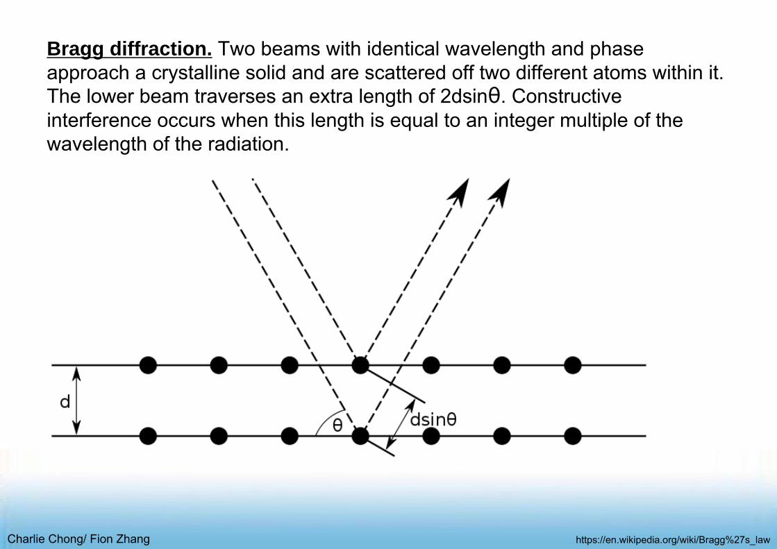
Bragg's lawIn physics, Bragg's law (or "Wulff -Bragg's condition" in postsoviet countries, a special case of Laue diffraction) gives the angles for coherent and incoherent scattering from a crystal lattice. When X-rays are incident on an atom, they make the electronic cloud move as does any electromagnetic wave. The movement of these charges re-radiates waves with the same frequency, blurred slightly due to a variety of effects; this phenomenon is known as Rayleigh scattering (or elastic scattering). The scattered waves can themselves be scattered but this secondary scattering is assumed to be negligible.
A similar process occurs upon scattering neutron waves from the nuclei or by a coherent spin interaction with an unpaired electron. These re-emitted wave fields interfere with each other either constructively or destructively (overlapping waves either add up together to produce stronger peaks or are subtracted from each other to some degree), producing a diffraction pattern on a detector or film. The resulting wave interference pattern is the basis of diffraction analysis. This analysis is called Bragg diffraction.
https://en.wikipedia.org/wiki/Bragg%27s_law

Charlie Chong/ Fion Zhang
Cold Neutrons“Materials possess high cross-sections at these energies. which decrease the transparency of most materials but also increase the efficiency of detection. Aparticular advantage is the reduced scatter in materials at energies below theBragg cutoff. (Less than 0.01 eV)”
Very low energy neutrons can offer advantages for some specializedinspections; the penetrating ability of neutrons can be greatly enhanced forsome radiographic specimens by taking advantage of the reduced scatter atneutron energies below the Bragg cutoff (the point where an energy'swavelength, compared to the specimen's atomic spacing, becomessufficiently long to prohibit diffraction). Specifically, iron becomes moretransparent at a neutron energy of about 0.005 eV because of reducedscatter. In fact, the use of cold neutrons allows radiographic inspection of ironspecimens in the thickness range of 10 to 15 cm. Another application for coldneutrons involves taking advantage of the high absorption cross sections inmany materials. This may allow the imaging of small concentrations ofmaterials, too small to be imaged well with thermal neutrons. The efficiency ofdetectors also increases in the cold energy region.

Charlie Chong/ Fion Zhang
Bragg diffraction (also referred to as the Bragg formulation of X-ray diffraction) was first proposed by William Lawrence Bragg and William Henry Bragg in 1913[1] in response to their discovery that crystalline solids produced surprising patterns of reflected X-rays (in contrast to that of, say, a liquid). They found that these crystals, at certain specific wavelengths and incident angles, produced intense peaks of reflected radiation. The concept of Bragg diffraction applies equally to neutron diffraction and electron diffraction processes.[2] Both neutron and X-ray wavelengths are comparable with inter-atomic distances (~150 pm) and thus are an excellent probe for this length scale.
According to the 2θ deviation, the phase shift causes constructive (left figure) or destructive (right figure) interferences.William Lawrence Bragg explained this result by modeling the crystal as a set of discrete parallel planes separated by a constant parameter d. It was proposed that the incident X-ray radiation would produce a Bragg peak if their reflections off the various planes interfered constructively. The interference is constructive when the phase shift is a multiple of 2π; this condition can be expressed by Bragg's law (see Bragg condition section below) and was first presented by Sir William Lawrence Bragg on 11 November 1912 to the Cambridge Philosophical Society. [3][4] Although simple, Bragg's law confirmed the existence of real particles at the atomic scale, as well as providing a powerful new tool for studying crystals in the form of X-ray and neutron diffraction. William Lawrence Bragg and his father, Sir William Henry Bragg, were awarded the Nobel Prize in physics in 1915 for their work in determining crystal structures beginning with NaCl, ZnS, and diamond. They are the only father-son team to jointly win. William Lawrence Bragg was 25 years old, making him then, the youngest physics Nobel laureate.
https://en.wikipedia.org/wiki/Bragg%27s_law

Charlie Chong/ Fion Zhang
Bragg diffraction. Neutron or X-rays interact with the atoms in a crystal.
https://en.wikipedia.org/wiki/Bragg%27s_law

Charlie Chong/ Fion Zhang
Bragg diffraction. According to the 2θ deviation, the phase shift causes constructive (left figure) or destructive (right figure) interferences.
https://en.wikipedia.org/wiki/Bragg%27s_law
Charlie Chong/ Fion Zhang
Bragg diffraction. Two beams with identical wavelength and phase approach a crystalline solid and are scattered off two different atoms within it. The lower beam traverses an extra length of 2dsinθ. Constructive interference occurs when this length is equal to an integer multiple of the wavelength of the radiation.
https://en.wikipedia.org/wiki/Bragg%27s_law

Charlie Chong/ Fion Zhang
X Ray & Neutron Interactions with Matters

Charlie Chong/ Fion Zhang
End Of Reading 2
Charlie Chong/ Fion Zhang
Reading-3Neutron Radiography State of Art Report - NTIAC-SR-98-01
Charlie Chong/ Fion Zhang
Charlie Chong/ Fion Zhang
1.0 INTRODUCTION1.1 ObjectiveNeutron radiography is becoming a well established nondestructive testing (NDT) method. The American Society for Nondestructive Testing (ASNT) hasrecognized the method through its recommended practice SNT-TC 1A whichoutlines training, knowledge, and experience necessary to obtain levels ofcompetency in the method (1, 2). Certification of nondestructive testingpersonnel is also covered in a military standard (3). Technical publications inthe field of NDT and nuclear technology carry articles on neutron radiographyand technical meetings includepapers or even entire sessions on neutronradiograph))~ There is an on-going series of international conferences onneutron radiography ( 4-11 ). Many books are available to provideintroductory and advanced material on neutron radiographic techniques andapplications (12-20).Neutron radiography as a service for hire is available,similar to that offered for other NDTservices. The method is being adopted to solve NDT problems in specialty areas.
Charlie Chong/ Fion Zhang
The objective of this report is to provide a brief survey of the current state of the art in the use of neutron radiography. The survey will include informationon the technique including principles of the method, sources of neutrons,detection methodology, standards and image quality indicators, andrepresentative applications. An extensive reference list provides additionalinformation for those who wish to investigate further and a Glossary isincluded which provides definitions for terms used in Neutron Radiography.

Charlie Chong/ Fion Zhang
1.2 ScopeThis report is based on a review of pertinent open technical literature as well as a review of recent progress in the field. The literature search was accomplished by the Nondestructive Testing Information Analysis Center through its computerized documentation data bases. The scope of this report includes introductory material with advantages and limitations of the method being presented along with a brief historical background. The theoretical section contains topics on neutron production, neutron energies, neutron interactions, neutron detection, geometric considerations, and neutron shielding. Neutron sources as well as moderators and collimators are discussed. Neutron imaging techniques, standards, and recommended practices are presented. Applications of neutron radiography to several important industrial and military areas are included. It is assumed that the reader is already familiar with conventional X-ray and/or gamma radiography. Many publications are available that can provide that background information if it is needed (22-25).

Charlie Chong/ Fion Zhang
1.3 DefinitionsNeutron radiography is a specialized type of radiography. The definition of the term given in American Society for Testing and Materials (ASTM) (26) is asfollows: "neutron radiographythe process of producing a radiograph usingneutrons as the penetrating radiation." The neutron is defined as, "a neutralelementary particle having an atomic mass close to 1.
In the free state outside of the nucleus, the neutron is unstable having a half-life of approximately 10 minutes.“ Additional definitions related to neutronradiography are given in ASTM document E 1316 (26) and in MIL-STD-1948(27). The radiation terminology now accepted is to use the term radiology toinclude any radiation technique that involves ionizing radiation, e.g. x-rays,gamma rays, neutrons, etc.
Charlie Chong/ Fion Zhang
Neutron radiography specifically refers to the film technique. Neutronradioscopy refers to the electronic production of a neutroh image that follows very closely the changes with time of the object being imaged.
Radioscopy is the term for what has been called real-time radiography. Other neutron radiological techniques include neutron gauging (typically using tightly collimated beams) and neutron activation analysis (analysis of radiation emitted by materials made artificially radioactive by absorption of a neutron by the nucleus of the atom).
In this report, the more familiar term neutron radiography will continue to be used except when reference is made specifically to neutron radioscopy (or real-time imaging).

Charlie Chong/ Fion Zhang
Most neutron inspection has been done with thermal neutrons, neutrons in the energy range from 0.005 to 0.5 eV (0.01ev ~ 0.3ev). These thermal neutrons show large differences in attenuation compared to those for x-rays, as discussed in Section 1.4. It is these large attenuation differences that make neutron radiography useful, usually providing almost a reversal of typical x-ray attenuation. In many cases radiographs taken with both x-rays and neutrons provide complementary information about the object.
Neutron radiography has also been done with cold neutrons (<0.01ev) . These very slow neutrons have energies below 0.005 eV. Greater radiographic contrast can often be obtained with these special neutrons. Sometimes the term slow neutrons is used to designate the cold and thermal neutron region and beyond, up to energies of several keV.
Charlie Chong/ Fion Zhang
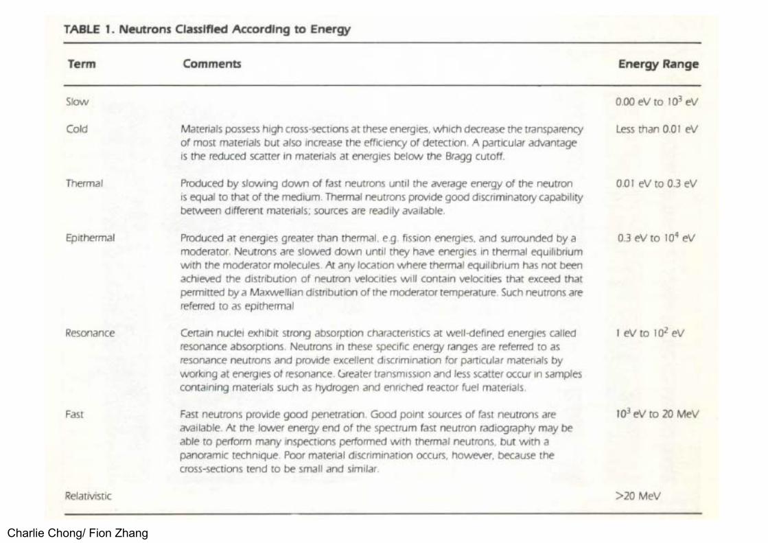
In addition, use has been made of epithermal neutrons (energy range slightly higher than thermal, typically above 0.5 eV, up to about 10,000 eV) and fast neutrons, which include energies above 10,000 eV, up to the MeV energy range. Neutrons with energies above 10 MeV are often termed relativistic because of the high velocities of these neutrons. Radiography has been done in all these energy ranges but thermal neutrons are most widely used. Table 1.1 contains a brief description of the energy ranges for neutrons and the properties.
The neutrons may be produced by an isotopic source, an accelerator, or a nuclear reactor and may be imaged by a variety of methods. Unlike otherforms of penetrating radiation, the neutrons must be converted into otherforms of radiation (light, alpha particles, beta particles, gamma rays, etc.)before being detected by a photographic emulsion or other devices.

Charlie Chong/ Fion Zhang
Table 1.1. Neutrons Classified According to Energy

Charlie Chong/ Fion Zhang
Table 1.1. Neutrons Classified According to Energy

Charlie Chong/ Fion Zhang
1.4 AdvantagesNeutron radiography complements X- and gamma radiography in many cases. While X- and gamma radiation are typically used to image high atomicnumber materials such as lead or steel by themselves or in low atomicnumber matrices such as plastic or rubber, neutron radiography best imageslow atomic number materials such as paper, plastic or rubber in a matrix of ahigh atomic number material such as lead or steel. As such, neutronradiography finds application to the detection of low atomic number materialssuch as "0"-rings, gaskets, adhesives or sealants, hydrogenous liquids likewater or petroleum products and corrosion.
A major neutron radiographic application has been the detection and characterization of explosives inside metal containers destined for critical aerospace and military service. Examples include verification of the explosive in explosive bolts, lines or detonating cord used to separate components in flight or space.
Charlie Chong/ Fion Zhang
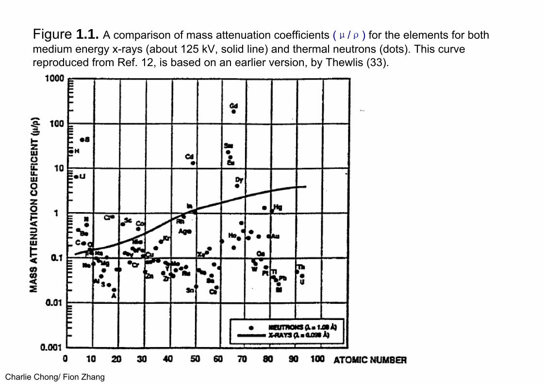
Figure 1.1. A comparison of mass attenuation coefficients (μ/ρ) for the elements for bothmedium energy x-rays (about 125 kV, solid line) and thermal neutrons (dots). This curvereproduced from Ref. 12, is based on an earlier version, by Thewlis (33).

Charlie Chong/ Fion Zhang
Charlie Chong/ Fion Zhang
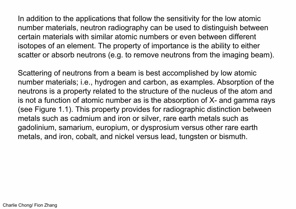
In addition to the applications that follow the sensitivity for the low atomic number materials, neutron radiography can be used to distinguish betweencertain materials with similar atomic numbers or even between differentisotopes of an element. The property of importance is the ability to eitherscatter or absorb neutrons (e.g. to remove neutrons from the imaging beam).
Scattering of neutrons from a beam is best accomplished by low atomicnumber materials; i.e., hydrogen and carbon, as examples. Absorption of theneutrons is a property related to the structure of the nucleus of the atom andis not a function of atomic number as is the absorption of X- and gamma rays(see Figure 1.1). This property provides for radiographic distinction betweenmetals such as cadmium and iron or silver, rare earth metals such asgadolinium, samarium, europium, or dysprosium versus other rare earthmetals, and iron, cobalt, and nickel versus lead, tungsten or bismuth.
Charlie Chong/ Fion Zhang
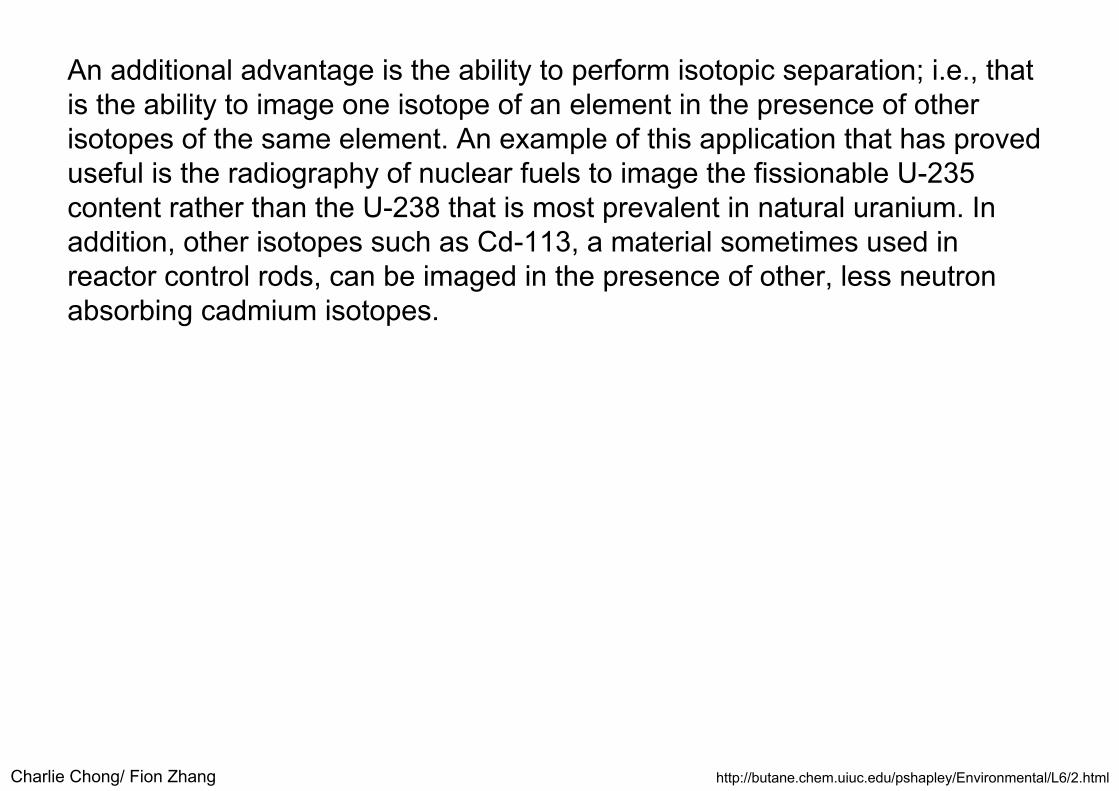
An additional advantage is the ability to perform isotopic separation; i.e., that is the ability to image one isotope of an element in the presence of otherisotopes of the same element. An example of this application that has proveduseful is the radiography of nuclear fuels to image the fissionable U-235content rather than the U-238 that is most prevalent in natural uranium. Inaddition, other isotopes such as Cd-113, a material sometimes used inreactor control rods, can be imaged in the presence of other, less neutronabsorbing cadmium isotopes.
http://butane.chem.uiuc.edu/pshapley/Environmental/L6/2.html

Charlie Chong/ Fion Zhang
Radioactive isotopes
http://butane.chem.uiuc.edu/pshapley/Environmental/L6/2.html
■ http://butane.chem.uiuc.edu/pshapley/Environmental/L6/2.html

Charlie Chong/ Fion Zhang
Indirect TechniqueRadiography of nuclear fuel is an example of another advantage of neutron radiography, the ability to radiograph intensely radioactive materials. Theradiation released by irradiated nuclear fuel would quickly overexposeradiographic film used for X- or gamma radiography. Neutron radiography ofradioactive objects is commonly done by neutrons which have passedthrough a specimen to produce a radioactive image on metal converter foilssuch as indium, dysprosium, silver or gold. The exposed, radioactiveconverter screen is removed from the intense radiation area of the fuel rodafter neutron exposure and placed in a film loaded cassette where theradioactivity induced in the screen by the neutrons exposes the film. Thelatent image on the film produced by this "indirect" technique comes from thebeta particles or gamma rays released by decay of the radioactive atomsproduced by neutron absorption. The film is an autoradiograph of theconverter screen and a neutron image of the inspection object without thefogging that might have been caused by the intense radioactive emissions.

Charlie Chong/ Fion Zhang
1.5 LimitationsRadiation safety precautions must be used with neutron inspection techniques as is necessary with other forms of radiation testing; i.e., there is apotential radiation hazard that requires practitioners be well informed,properly equipped and organized to handle radiation and radioactivematerials. The neutron radiographer needs formal training and experiencethat is not satisfied by training and experience with X- or gamma radiography(although training for X- and gamma radiography is an excellent start). Asimilar, or more extensive, radiation safety program is required as comparedto X- and gamma radiography. The dosimetry used, such as survey meters, area monitors and personnel dosimeters must be sensitive to neutrons.
Charlie Chong/ Fion Zhang
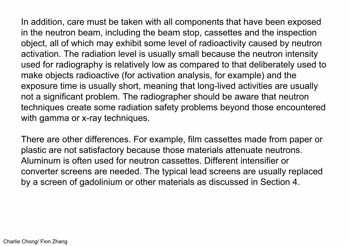
In addition, care must be taken with all components that have been exposed in the neutron beam, including the beam stop, cassettes and the inspectionobject, all of which may exhibit some level of radioactivity caused by neutronactivation. The radiation level is usually small because the neutron intensityused for radiography is relatively low as compared to that deliberately used tomake objects radioactive (for activation analysis, for example) and theexposure time is usually short, meaning that long-lived activities are usuallynot a significant problem. The radiographer should be aware that neutrontechniques create some radiation safety problems beyond those encounteredwith gamma or x-ray techniques.
There are other differences. For example, film cassettes made from paper or plastic are not satisfactory because those materials attenuate neutrons. Aluminum is often used for neutron cassettes. Different intensifier or converter screens are needed. The typical lead screens are usually replaced by a screen of gadolinium or other materials as discussed in Section 4.

Charlie Chong/ Fion Zhang
The neutron sources are discussed in Section 3. Typical sources for neutron radiography include isotopes, accelerators and reactors. These tend to bemore expensive than those used for X- or gamma radiography. This isparticularly true if large, high output sources are desired to permit rapid, goodresolution neutron radiographs to be made. Properly collimated and shieldedisotopic sources may easily cost $100,000, while large accelerators andreactors will cost from about $500,000 to well over $1,000,000, plus the costof a building or specially shielded laboratory. The availability of neutronradiography to those wishing to purchase the service rather than set up theirown laboratory may not be as convenient as that for X-radiography. A neutronradiography customer must often ship specimens to a distant facility with theattendant extra costs and time lost.
Charlie Chong/ Fion Zhang
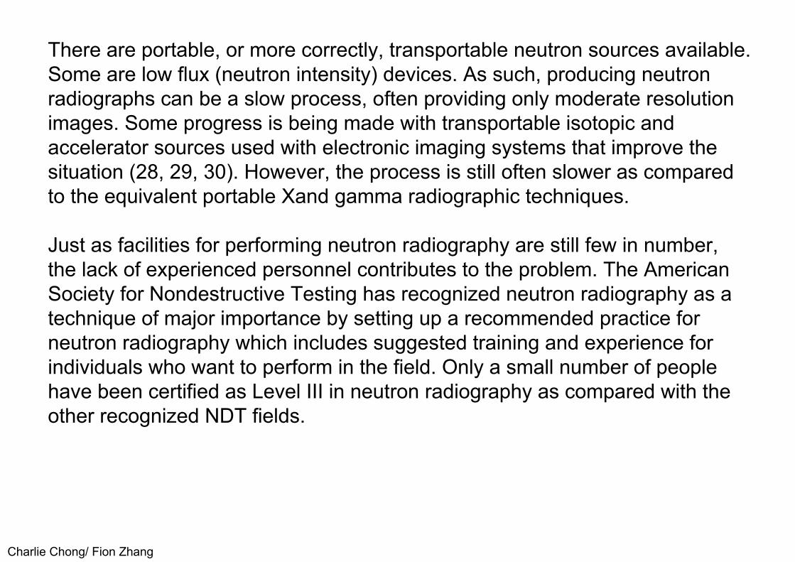
There are portable, or more correctly, transportable neutron sources available. Some are low flux (neutron intensity) devices. As such, producing neutronradiographs can be a slow process, often providing only moderate resolutionimages. Some progress is being made with transportable isotopic andaccelerator sources used with electronic imaging systems that improve thesituation (28, 29, 30). However, the process is still often slower as comparedto the equivalent portable Xand gamma radiographic techniques.
Just as facilities for performing neutron radiography are still few in number, the lack of experienced personnel contributes to the problem. The American Society for Nondestructive Testing has recognized neutron radiography as a technique of major importance by setting up a recommended practice for neutron radiography which includes suggested training and experience for individuals who want to perform in the field. Only a small number of people have been certified as Level III in neutron radiography as compared with the other recognized NDT fields.

Charlie Chong/ Fion Zhang
1.6 Historical DevelopmentThe earliest research on neutrons for radiography was the work of Kallmann and Kuhn in Germany, in 1935. This pioneering work resulted in numerous patents and one publication which was held up until after World War II (31).Kallmann used an accelerator source with a neutron yield of about 4 x 10⁷
neutrons per second. This low output source necessitated the use of longexposures, about 4 hours per radiograph. Peter's early neutron radiographicwork in Germany made use of a more intense accelerator source thatpermitted a neutron radiograph to be made in a few minutes (32).
The first reactor neutron radiographic work published was by Thewlis in 1956 (33). Thewlis and his co-worker Derbyshire used the BEPO reactor at Harwellin England. The reactor neutron radiographs, made with the better collimatedand more intense neutron source, produced very good quality images ascompared to the earlier accelerator neutron source radiographs. Thewlis alsopointed the way for practical applications of neutron radiography.

Charlie Chong/ Fion Zhang
As neutron sources became more available in the 1960's more neutron radiographic work was reported with emphasis on both techniques andapplications. Extensive developments of techniques and applications werereported by many investigators during the 1960's. Some of that work wasstimulated by the 1965 publication of a book on neutron radiography (12).Early work on neutron radiography in the United States was summarized in a1991 review article (34). By the beginning of the 1970's there wereapproximately 40 installations at which neutron radiography was beingperformed. Developments in the 1970's are summarized in several reviews ofthat period (13, 14, 15). World-wide facilities for neutron radiographic worknumbered over 100, as reported at a 1995 international conference (35).

Charlie Chong/ Fion Zhang
2.0 THEORY2.1 Neutron Production PrinciplesNeutron production for neutron radiography may be accomplished using radioisotope sources, accelerators, or nuclear reactors. Generally speaking, the intensity of thermal neutron beams for radiography is greatest for reactor systems, followed by lower intensity beams from accelerator and radioisotope sources. There are exceptions to that generalization. The cost of neutron sources tends to follow the same order, with reactor sources being priced higher, typically at well over a million dollars.

Charlie Chong/ Fion Zhang
Sources of neutrons usually provide fast neutrons. These fast neutrons must be slowed down, a process called moderation or thermalization, if theneutrons are to be used for thermal neutron radiography and take advantageof the attenuation differences previously shown in Figure 1.1. Moderators,materials that usually surround a fast neutron source to create a source ofthermal neutrons, are typically made of low atomic number material such ashydrogen or carbon. Water and hydrocarbon materials such polyethylene areoften used, in sizes approaching a cubic meter.
The fast neutrons lose energy by collisions with the moderator material, eventually coming into "thermal equilibrium" with the moderator, hence the term thermal neutrons. The higher the neutron energy, the more difficult the moderation process becomes, because more scattering reactions must be used. As a rule of thumb, the fast neutron yield in neutrons/second (n/s) isreduced by a factor of 100 to 1 ,000 for the peak thermal neutron flux within the moderator (1/100, 1/1000 or 1/100000?) . Collimation, that is bringing a useful beam out of the large moderator, will further reduce the neutrons available in a beam for radiography. The total reduction from the neutron yield in terms of n/s to a thermal neutron radiographic beam in terms of n/cm2∆s can be a million times or more (36).

Charlie Chong/ Fion Zhang
2.2 Neutron EnergiesAs noted in the preceding sections, neutrons normally possess large kinetic energies when they are produced. However, for neutron radiography andmany other applications, neutrons with very low or thermal energies are mostuseful. Thermal neutrons are neutrons that possess a kinetic energy relatedto the temperature of their surroundings; i.e., at 20°C the (thermal) neutronwould have a kinetic energy of 0.025 eV. These low kinetic energy neutronsare also called 'slow' neutrons although they are traveling at a velocity of2200 meters/s. To thermalize or slow down a neutron, the neutron is allowed to move through a low atomic number substance such a water, graphite, orberyllium. Collisions of the neutrons with the low atomic number materials,especially hydrogen, reduce the neutron's kinetic energy by transfer of theirkinetic energy to the nuclei of the atoms. Hydrogen is most effective becauseit has a nucleus with essentially the same mass as the neutron. Hydrogen isalso effective because it has a low probability of thermal neutron absorption.

Charlie Chong/ Fion Zhang
Neutrons with sufficient energy to be transmitted through thin cadmium foil are call epicadmium or epithermal neutrons and have kinetic energies greaterthan 0.5 eV. Neutrons with energies above the cadmium cutoff energy of 0.5eV and below approximately 10 keV are called epithermal neutrons (althoughother energies are sometimes used as separation points). Neutrons withkinetic energies above 10 keV are referred to as fast neutrons. Neutrons withenergies below about 0.005 eV are designated as cold neutrons and requiremoderators cooled to liquid nitrogen or lower temperatures. Refer to Table 1.1for additional information.

Charlie Chong/ Fion Zhang
As the kinetic energy of the neutron decreases, the probability of it's absorption in a nucleus increases. This probability is called the microscopic cross section of the nucleus and is given in units of area such as square centimeters (37).
Cross section is not a real area but rather an effective area represented by the probability of the neutron interaction. An example is the cross section of Boron-10 for thermal neutrons of 3,838 barns (a barn is equivalent to 10-24
square centimeters) while the cross section of Boron-11 is only 5 millibarns.
Obviously there is not six orders of magnitude difference in the areas of the two nuclei but there is six orders of magnitude difference in the probability of neutron interaction by the two nuclei. Cross section varies widely with structure of the nucleus, energy of the neutron, and reaction between the neutron and nucleus.
Charlie Chong/ Fion Zhang
2.3. Neutron Interactions, Scattering, Nuclear Absorption, FissionA brief discussion· of neutron interactions is important to understanding how neutrons may be used for radiography. Concepts, which include shielding,detection, thermalization or moderation, and collimation, depend upon howneutrons interact with materials. Neutron interactions of most importance arescattering, nuclear absorption, and fission. Each of these is discussed brieflybelow. Additional background information can be found in textbooks onnuclear physics or nuclear engineering (38-42).
■ ScatteringScatter is an important way for neutrons to be removed from a beam and to lose kinetic energy (become thermalized or moderated). Neutron scattering occurs when neutrons collide with the nuclei of atoms. Note that neutrons pass through the electron clouds surrounding atoms without detectable interaction. Interactions are with the nuclei of the atoms. Neutrons may scatter from interaction with a nucleus in either an elastic or inelastic fashion.
Charlie Chong/ Fion Zhang
When a neutron undergoes elastic scattering it is as if the neutron and the nucleus were "billiard balls." The initial energy of the neutron (assuming thenucleus is at rest) is distributed between the neutron and nucleus accordingto the laws of conservation of kinetic energy and momentum. This distributionwill depend on the mass of the nucleus and the angle of scatter. The recoilenergy of the nucleus results in heating of the moderator. This mode ofinteraction is particularly important for lower energy neutrons and interactionswith low atomic number nuclei, where a neutron can lose a significant fractionof its energy in a single collision.
Inelastic scatter occurs when the initial energy of the neutron is sufficient to "excite" the nucleus to an allowed quantum energy level above the ground state. The difference in energy between the ground state and the excited state is no longer available to the scattered neutron and recoil nucleus. The kinematics (energy, momentum and scattering angles) of the collision are then determined with this reduced energy. The excited nucleus returns to the ground state via emission of one or more gamma photons. Inelastic scatter becomes more important as neutron energies increase or the atomic number of the target nuclei increase.

Charlie Chong/ Fion Zhang
■ Nuclear AbsorptionNeutrons may enter the nucleus of an atom quite easily, as compared to charged particles since there is no coulomb or charge repulsion to overcome.If the neutron remains in the nucleus, excess energy (binding energy) orparticles must be released from the nucleus. For a thermal neutron, thisenergy release most likely occurs in the emission of a photon from thenucleus. Such reactions are designated as (n,γ), capture, or activationreactions. The product of an (n, γ) (pronounced n-gamma) reaction is mostoften, but not always, unstable or radioactive. As neutron energy increasesabove thermal energies, the probability of an (n, γ) reaction decreases. Athigher kinetic energies, absorption of the neutron by a nucleus is followed bythe release of a proton, an alpha particle, or two or more neutrons. Thesereactions are often designated: (n,p), (n, α), and (n,2n). Probabilities for these reactions vary widely with the structure of the target nucleus but generally increase with increasing kinetic energy of the neutron. Products ofthese reactions are often radioactive.

Charlie Chong/ Fion Zhang
FissionFission occurs when a neutron with the proper energy enters a nucleus causing it to split into two smaller nuclei.
Uranium-235, Plutonium-239, and Thorium-233 fission upon absorption of athermal neutron. Uranium-238 will fission after the absorption of a fast or high energy neutron. Califomium-252 is already unstable and will spontaneously fission; i.e., will fission without the necessity of a neutron being absorbed to initiate fission (SF) . The products of each fission are two smaller (radioactive) nuclei and 2 to 3 free neutrons, on average.
The neutrons are released with an average energy of over 2 MeV (fast neutron) and generally must be slowed down; i.e., thermalized, to be used for either additional fission reactions or for neutron radiography.

Charlie Chong/ Fion Zhang
■ Mathematical Relationships(1) The following equation can be used to determine the approximate intensity of a parallel neutron beam traversing a material of thickness x.
I= Io e-Nσx Eqn. 2.1
This equation assumes a point detector, monoenergetic neutrons and interaction (absorption or scatter) that removes the neutron from the beam. The quantities are defined below:
I is neutron intensity with absorber thickness xIo is neutron intensity with no absorberN is atoms per cubic centimeter (cm3) in absorberσ is the total microscopic cross section of atoms in this absorber ( cm2)x is thickness of absorber (cm)

Charlie Chong/ Fion Zhang
For thick absorbers, a build-up factor of (B) is used to account for neutrons scattered into the point of neutron detection.
I= B∙Io e-Nσx Eqn. 2.2
B is approximately 5 for thick absorbers containing hydrogen.
The macroscopic cross section (:E) is defined as:
Σ(μ) = Nσ Eqn. 2.3
Σ(μ) = σ(ρNavocados)/A
N = is the total number of target atoms of the isotope involved in the neutron reaction
Navocados = 6.02 x 10⁻²³
A= gram atomic (molecular) weight

Charlie Chong/ Fion Zhang
and carries units of reciprocal length. The macroscopic cross section is the probability of interaction per unit length and may be substituted in the above equations to give:
I= Io e-Σx , I= B∙Io e -Σx , I= B∙Io e –μx , Eqn. 2.4

Charlie Chong/ Fion Zhang
(2) Materials irradiated with neutrons can become radioactive. The following equation can be used to estimate the level of activity:
A = NσΦ(1- e-0.693t/T) Eqn. 2.5
where the quantities are defined below:• A= is the activity in disintegrating atoms per second at the end of neutron
irradiation• N= is the total number of target atoms of the isotope involved in the
neutron reaction• σ= is the absorption microscopic cross section for the isotope and neutron
reaction under consideration ( cm2)• Φ= is the neutron flux in n∙cm2·sec-1
• t= is the time of neutron irradiation• T= is the half life of the radioisotope produced.

Charlie Chong/ Fion Zhang
This takes into account that the radioactive nuclei decay while they are being produced and assumes that the neutron flux is not appreciably reduced in travel through the material. For thick absorbers this correction must be made.After the material is removed from the neutron environment there is no furtherproduction and the activity will decay according to the half-life.
N = Noe-0.693t/T
d N = -λNdtd N/N = -λdtln N = -λt + CN = e-λt eC
When t = 0No = eC
N = Noe-λt
When t= T½ , N/No = e -λT½
ln 0.5 = - -λt, λ = 0.693/T½

Charlie Chong/ Fion Zhang
2.4 Radioisotope Sources, Accelerator Sources, Nuclear ReactorsVarious sources for neutron radiography are briefly described. Major categories of sources are radioistopes, accelerators and nuclear reactors, (subcritical assembly) . Radioisotope Sources There are two types of radioisotope sources, those that depend on fission and those that require aradiation such as alpha particles or gamma rays incident on an appropriate target nucleus. An example of the first type is Cf-252 which spontaneously splits apart in a fission reaction. The other type involves combinations of alpha (or gamma) emitting radioisotopes with an element such as beryllium. The alpha emitting types are important for the latter category.
Charlie Chong/ Fion Zhang
Cf-252, which spontaneously undergoes a fission reaction that releases neutrons, has become one of the major radioisotope neutron sourcesbecause it offers a reasonably long half life (2.6 years), produces a moderateenergy neutron (fission spectrum with a neutron average energy of about 2.3MeV), and a relatively high yield, typically 100 times as many neutronsemitted per gram, as compared to other radioisotope sources. Californium isa man-made element.
The Cf-252 isotope has been available at a moderate cost ($10 to $20 per microgram.) However, the cost of these sources is high because encapsulation, moderation, collimation and shipping far outweigh the cost of the source material. It has been used where cost was less important than portability and neutron output. For example, the robotic neutron system at McClellan Air Force Base, used for on-aircraft inspection, made use of Cf- 52 as the neutron source (29).
Charlie Chong/ Fion Zhang
An advantage of the Cf-252 source is the ease of moderating the fast neutrons to produce a beam of thermal neutrons. Moderation is somewhat easier because the small source size means that the moderator material can closely surround the source and because the energy of the emitted neutrons is reasonably low (fission spectrum with an average energy of about 2.3 MeV).
The high neutron yield, coupled with a thermalization factor of 100 or less (the ratio of the fast neutron yield to the peak thermal neutrons per square cm-second in the moderator, see Ref. 35) means that a 1 milligram source (fast neutron yield of 3 x 10⁹n/s) could produce a peak thermal neutron flux in a well designed moderator of about 3 x 10⁷n/cm2∙s and, with collimation losses, perhaps a crudely moderated radiographic beam of 103 to 104n/cm2∙s.
Comments:thermalization factor - the inverse ratio of the thermal neutron flux obtainedin a moderator, per source neutron.

Charlie Chong/ Fion Zhang
Thermalization Factor: When reactors is used as a source for thermalneutron radiography, the moderating body that hosts the source is applied inorder to supply the largest possible flux of thermal neutrons in a region fromwhich the beam may be extracted by the collimator. Then, an importantparameter is the thermalization factor (TF), which is determined by (3):
TF = Fast neutron yieldPast thermal flux
The best moderator to use with a reactor neutron source is commonly the onein which a small value for TF can be accepted [6]. The first step of analysis,calculations were carried out to evaluate the efficiency of the thermalmoderation of some selected materials. The chosen geometric configurationwas a cylindrical system with 208 cm length and 6.7 cm inlet diameter ofprimary collimator. A reactor source is placed in distance of 86.29 cm of inletaperture of the collimator.
http://idosi.org/mejsr/mejsr11(5)12/17.pdf
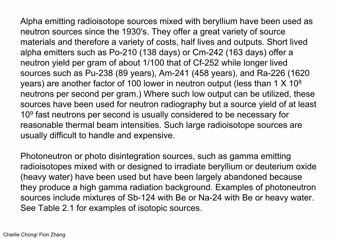
Charlie Chong/ Fion Zhang
Alpha emitting radioisotope sources mixed with beryllium have been used as neutron sources since the 1930's. They offer a great variety of sourcematerials and therefore a variety of costs, half lives and outputs. Short livedalpha emitters such as Po-210 (138 days) or Cm-242 (163 days) offer aneutron yield per gram of about 1/100 that of Cf-252 while longer livedsources such as Pu-238 (89 years), Am-241 (458 years), and Ra-226 (1620years) are another factor of 100 lower in neutron output (less than 1 X 10⁸
neutrons per second per gram.) Where such low output can be utilized, thesesources have been used for neutron radiography but a source yield of at least109 fast neutrons per second is usually considered to be necessary forreasonable thermal beam intensities. Such large radioisotope sources areusually difficult to handle and expensive.
Photoneutron or photo disintegration sources, such as gamma emitting radioisotopes mixed with or designed to irradiate beryllium or deuterium oxide (heavy water) have been used but have been largely abandoned because they produce a high gamma radiation background. Examples of photoneutron sources include mixtures of Sb-124 with Be or Na-24 with Be or heavy water. See Table 2.1 for examples of isotopic sources.
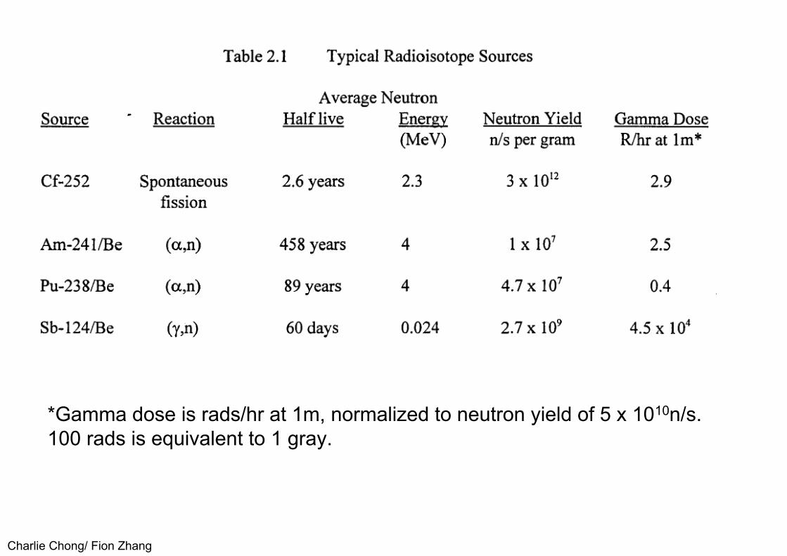
Charlie Chong/ Fion Zhang
*Gamma dose is rads/hr at 1m, normalized to neutron yield of 5 x 10¹⁰n/s.100 rads is equivalent to 1 gray.

Charlie Chong/ Fion Zhang
Accelerator SourcesAccelerator sources of neutrons usually offer the advantages of higher output over isotope sources together with the ability to turn the radiation on and off.Neutron yields begin at about 107n/s and may be as high as 1012n/s.
One of the less expensive neutron accelerators is the Cockcroft-Walton accelerator (43) which can produce neutrons through either the (d,D) or (d,T)reactions at moderate accelerating potentials (from 100 to 400 KeV). In both reactions deuterium is ionized and the deuterons are accelerated toward targets of deuterium for the (d,D) reaction and targets containing tritium for the (d,T) reaction. The (d,D) reaction produces neutrons with an energy of about 2.5 MeV while the (d,T) reaction produces neutrons with an energy ofabout 14 MeV. The 14 MeV neutrons are more difficult to slow down to thermal energies (moderate) but the reaction yield at 150 keV is 60 times better. The (d,T) source has been a widely used source for thermal neutron radiography because of the high neutron yield.
Charlie Chong/ Fion Zhang
Typically the neutron generators have been used with a sealed neutron tube to avoid tritium radiation safety problems. Neutron yields decrease with time because of tube gassing problems and depletion of the tritium as it is bombarded by the deuteron beam. Some machines use a mixture of deuterium and tritium to ionize and accelerate into the target to help reduce target depletion. Modern versions of these accelerators can easily be used in a laboratory or fixed radiographic facility and are also designed to be transportable for mobile or field inspection applications ( 44, 45).
Charlie Chong/ Fion Zhang
New types of accelerators have been developed as sources for neutron radiography. These include modern radio frequency quadrupole accelerators (28,30,35,46) and cyclotrons (47). Both types of accelerators make use of neutron reactions such as protons on beryllium targets.
These relatively expensive machines can produce very high intensity beams for neutron radiography, typically 106n/cm2∙s, in well collimated beams. ( A new accelerator source based on the spallation process, is now being used for neutron radiography. This fixed installation source designed for research applications is capable of producing extremely well collimated thermal neutron radiographic beams of high intensity. Beam characteristics have been described to produce a useful thermal neutron flux of 5 x 10⁶n/cm2·s at the unusually large L/D of over 500 (48).
Be(p,n)B?, TF=300

Charlie Chong/ Fion Zhang
Van de Graaff accelerators have been used for neutron production. Again, the (d,D) and (d,T) reactions may be used with the ( d,D) reaction being favoredbecause neutron yield increases with increasing acceleration voltage whilethe yield of the ( d, T) reaction decreases above about 400 keV.
Be(p,n) sourceA well used reaction for Van de Graaff generation of neutrons is the acceleration of deuterons into beryllium targets. Large Van de Graaff machines can produce useful beams of thermal neutrons for radiography; beam intensities of more than 106n/cm2∙s have been obtained (49).
(x,n) sourceMachines designed for production of high energy x-ray photons may also produce neutrons by allowing the photons to interact with either beryllium or uranium-238 metal. Relatively high yield and long target life are characteristic of this type of production but the Linac type of accelerators also produce an intense x-ray background which can make it difficult to perform neutron radiography.

Charlie Chong/ Fion Zhang
■ Nuclear ReactorsSmall research reactors which fission uranium-235 to produce neutron flux in the range of 1011 to 1013 (n/cm2∙s) neutrons per square centimeter per second have been used very successfully for neutron radiography. While the source cost is high, the cost per neutron is less than for isotope or accelerator sources. The high neutron fluxes, 100 to 1000 times that of isotope or accelerator sources, permit very high quality neutron radiographic imaging with the short exposure times. Reactors do not offer the advantage of portability and are subject to regulation (50).
Sub-critical AssembliesUranium neutron multipliers called sub-critical assemblies have been used for neutron radiography. The sub-critcal assembly resembles a reactor in that uranium fission produces most of the neutrons. However, the sub-critical assemblies cannot reach the condition of producing a self-sustaining fission reaction. The assemblies produce multiplications of the neutrons from other neutron sources such as Cf-252. A multiplication of about 30, a significant increase in the number of neutrons available for radiography, can be obtained. A source of this type was used for many years to inspect critical weapon components (51, 52).

Charlie Chong/ Fion Zhang
2.5 Neutron Detection, Converter ScreensNeutron detection, for the purpose of radiography, is complicated by the need to convert the neutron to other types of radiation.· The neutron is very difficultto detect by 'direct' interaction of the neutron with matter. However, thesecondary radiation (photons, protons, and alpha particles) and decay of theradioactive nuclei produced by neutron absorption offer adequate andsometimes advantageous means for neutron detection. Converter screensare more important for neutron radiography than for X-ray or gammaradiography.
Film is more sensitive to the photon radiation than to the neutrons. Film is very sensitive to the secondary radiation produced by the neutrons. The neutron radiography converter screens utilize the secondary radiation from neutron absorption or the decay radiation from radioactive products of neutron absorption.
The prompt emission types of converter screens are used for direct neutron radiography. Screens that tend to become radioactive are used for transfer orindirect neutron imaging.
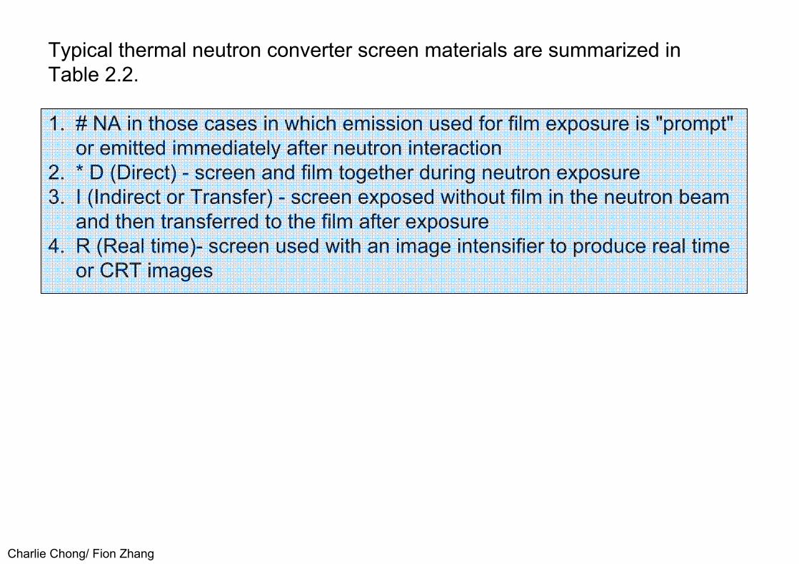
Charlie Chong/ Fion Zhang
Typical thermal neutron converter screen materials are summarized inTable 2.2.
1. # NA in those cases in which emission used for film exposure is "prompt" or emitted immediately after neutron interaction
2. * D (Direct) - screen and film together during neutron exposure3. I (Indirect or Transfer) - screen exposed without film in the neutron beam
and then transferred to the film after exposure4. R (Real time)- screen used with an image intensifier to produce real time
or CRT images
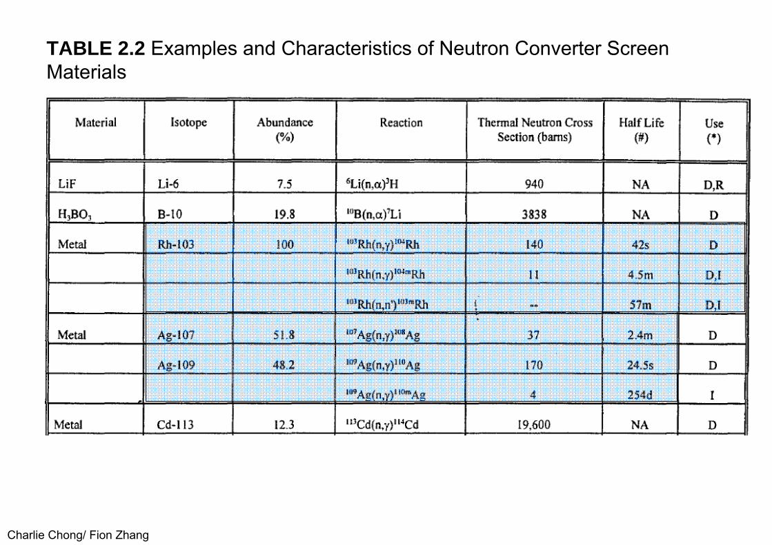
Charlie Chong/ Fion Zhang
TABLE 2.2 Examples and Characteristics of Neutron Converter Screen Materials

Charlie Chong/ Fion Zhang

Charlie Chong/ Fion Zhang
Converter Screens for Direct Neutron RadiographyDirect neutron radiography places the specimen, converter screen and film (or other imaging system) in the neutron beam at the same time as illustrated in the upper part of Figure 2.1. The converter screen changes the neutrons that have been transmitted through the specimen into radiation that can be detected by the film. Converter screens for this type of neutron radiographyare selected from materials that undergo prompt reactions upon neutron absorption, materials such as gadolinium or cadmium, for example.
Materials that exhibit radioactive reactions with short half-lives can also beconsidered for direct neutron radiography; materials such as silver or rhodium converter screens are good examples of short lived radioactive converter materials.
Charlie Chong/ Fion Zhang
Direct converter screens also make use of the conversion of the neutron to alpha particles by either Boron-10 or Lithium-6. The alpha particles have avery short range so few would escape a converter screen having a thicknessadequate for normal handling. Instead, the alpha particles are usuallycombined with a phosphor so the screen emits light upon neutron absorption.A popular high sensitivity screen has been made by mixing lithium fluorideenriched in Lithium-6 with scintillation grade zinc sulfide. The scintillationscreens are used with film sensitive to the light emitted from the screen. Thescintillation screen and alpha emitter combinations produce much faster results, exposures 100 times or more shorter exposures as compared to thetypically used screens of gadolinium. Since the scintillation screen images areproduced with fewer neutrons, (?) the images are often grainy or mottled ascompared to metal converter screen images.

Charlie Chong/ Fion Zhang
Some special plastic materials such as nitrocellulose and polycarbonates can produce images from exposure to the alpha particles. The alpha particlesproduce damage in the plastic that can be attacked by chemical agents. Suchmaterials are identified as track-etch films.
Track-Etch Technique An advantage of the track-etch method is insensitivity to gamma radiation
(one major application of track-etch is radiography of irradiated, radioactive nuclear fuel).
It is also convenient to work with these materials in the light without the need for a darkroom.
The alpha particle track-etch method also offers images with good spatialresolution because of the short range of the charged alpha particle.

Charlie Chong/ Fion Zhang
Figure 2.1 Diagrams illustrating the direct film exposure method (upper view)and the indirect, or transfer method (lower view), in which the film is notdirectly exposed to the neutron imaging beam (Ref. 12)
direct film exposure method
Charlie Chong/ Fion Zhang
Converter Screen for Indirect Neutron RadiographyIndirect or transfer neutron radiographic screens use the decay of radioactive products formed in the converter screen. The indirect technique places onlythe specimen and converter screen together in the neutron beam. Afterexposure to the neutrons, the screen is removed from the neutron beam andplaced in contact with film to produce the radiograph, as shown in the lowerpart of Figure 2.1. The film will be exposed to the radiation that results fromthe decay of the radioactive isotope(s) produced in the screen during neutronexposure. Indirect neutron radiography offers a method to radiograph highlyradioactive specimens that would produce exposure of the film if it werepresent during the radiographic exposure. The indirect technique is usuallyslower than the direct film method, since two exposures are required, one inthe beam to produce the radioactive image and one on the film to produce theautoradiograph.

Charlie Chong/ Fion Zhang
Figure 2.1 Diagrams illustrating the direct film exposure method (upper view)and the indirect, or transfer method (lower view), in which the film is notdirectly exposed to the neutron imaging beam (Ref. 12)
transfer method

Charlie Chong/ Fion Zhang
Converter Screens for Neutron Radioscopy (Real-Time Imaging)Thermal neutron image intensifiers have been used to convert an incoming thermal neutron image into a bright light image that can be detected by asensitive TV camera, a technique similar to that used for x-radioscopy. Tobest utilize the image intensifier, the converter screens involve scintillationwhich is excited by the alpha emission from lithium or boron, often combinedwith an efficient phosphor, such as ZnS.
The phosphor gadolinium oxysulfide offers high sensitivity to thermal neutrons because of the very high neutron cross section of gadolinium.
With the availability of modern, sensitive charged coupled device (CCD) cameras, many neutron radioscopic systems now use a sensitive scintillator or fluorescent screen observed by a CCD camera through a turning mirror (to place the camera out of the direct radiation beam). A typical radioscopic camera system is shown in Figure 2.2.
Charlie Chong/ Fion Zhang
Optics between the screen and optional image intensifier and camera are not shown. Many of these scintillator-CCD camera systems use the neutron scintillator LiF-ZnS(Ag), enriched in Li-6. The alpha emission excited by neutron absorption in the Li-6 nucleus, and the companion triton (3
1H+?) both contribute to light emission from the ZnS phosphor. These digital systems can offer large area coverage, wide dynamic range and good spatial resolution (28, 29, 30, 47, 48).

Charlie Chong/ Fion Zhang
Figure 2.2 Diagram of typical radioscopic imaging system. The turning mirror removes the camera from the direct radiation beam. The image intensifier is optional; optics are not shown. The CCD camera is often used in neutron radioscopic systems.
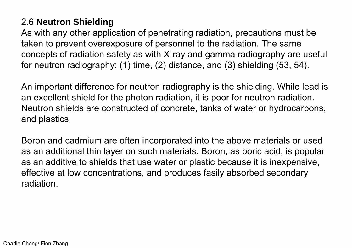
Charlie Chong/ Fion Zhang
2.6 Neutron ShieldingAs with any other application of penetrating radiation, precautions must be taken to prevent overexposure of personnel to the radiation. The sameconcepts of radiation safety as with X-ray and gamma radiography are usefulfor neutron radiography: (1) time, (2) distance, and (3) shielding (53, 54).
An important difference for neutron radiography is the shielding. While lead is an excellent shield for the photon radiation, it is poor for neutron radiation. Neutron shields are constructed of concrete, tanks of water or hydrocarbons, and plastics.
Boron and cadmium are often incorporated into the above materials or usedas an additional thin layer on such materials. Boron, as boric acid, is popularas an additive to shields that use water or plastic because it is inexpensive,effective at low concentrations, and produces fasily absorbed secondaryradiation.

Charlie Chong/ Fion Zhang
Secondary radiation, especially the conversion of neutrons to high energy gamma photons, must be recognized in the planning of the shielding forpersonnel. Much of the personnel exposure at neutron radiographic facilitiescomes from the secondary radiation rather than from the neutrons. Secondaryradiation shielding uses the concrete and lead common for the more commonradiographic facilities. Attention should be paid to the high energies of thesecondary radiation such as capture gamma rays. Attention should also bepaid to the handling of the converter screens which can become ratherradioactive in the high neutron fluxes available at nuclear reactors. The betaand other soft radiation emitted by the converter screens can easily beoverlooked and can produce appreciable exposure to the hands. Finger ringdosimeters should be considered for handling radioactive screens.Appropriate dosimeters and survey instrumentation for the neutrons, thesecondary radiation and the decay radiation are important and different fromthat used in either X-ray or gamma ray radiography.

Charlie Chong/ Fion Zhang
3.0 NEUTRON SOURCES, MODERATION AND COLLIMATIONNeutrons are created in neutron sources as high energy neutrons. From the previous discussions, thermal or low energy neutrons are preferred for mostneutron radiography applications. Therefore this section starts with adiscussion of methods for moderation or thermalization of neutrons.
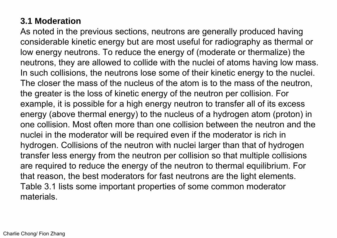
Charlie Chong/ Fion Zhang
3.1 ModerationAs noted in the previous sections, neutrons are generally produced having considerable kinetic energy but are most useful for radiography as thermal or low energy neutrons. To reduce the energy of (moderate or thermalize) the neutrons, they are allowed to collide with the nuclei of atoms having low mass. In such collisions, the neutrons lose some of their kinetic energy to the nuclei. The closer the mass of the nucleus of the atom is to the mass of the neutron, the greater is the loss of kinetic energy of the neutron per collision. For example, it is possible for a high energy neutron to transfer all of its excess energy (above thermal energy) to the nucleus of a hydrogen atom (proton) in one collision. Most often more than one collision between the neutron and the nuclei in the moderator will be required even if the moderator is rich in hydrogen. Collisions of the neutron with nuclei larger than that of hydrogen transfer less energy from the neutron per collision so that multiple collisions are required to reduce the energy of the neutron to thermal equilibrium. For that reason, the best moderators for fast neutrons are the light elements. Table 3.1 lists some important properties of some common moderator materials.

Charlie Chong/ Fion Zhang
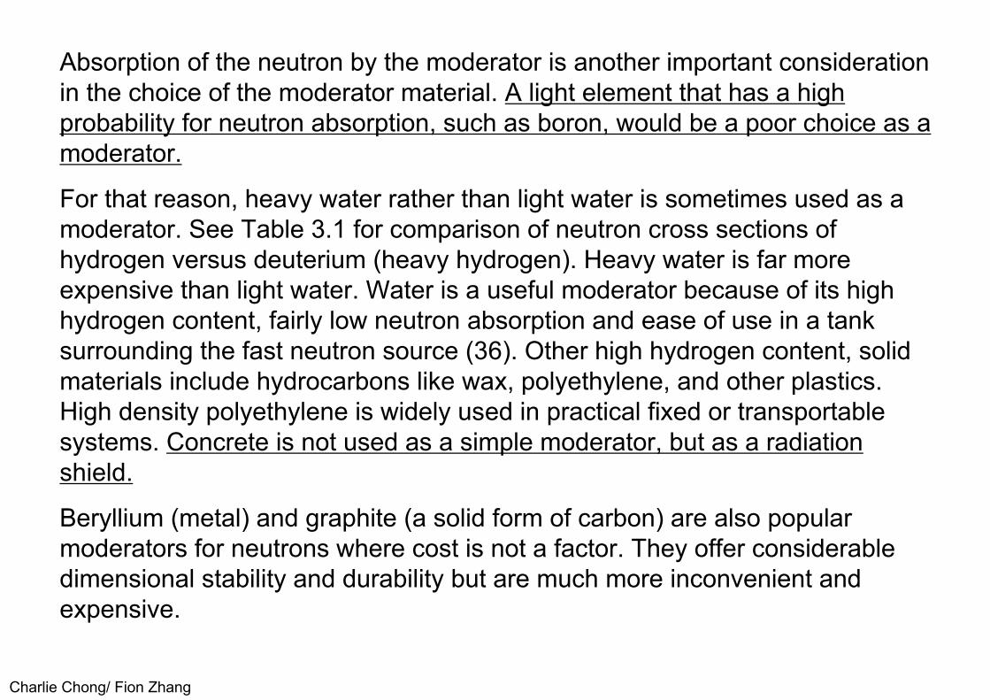
Charlie Chong/ Fion Zhang
Absorption of the neutron by the moderator is another important consideration in the choice of the moderator material. A light element that has a highprobability for neutron absorption, such as boron, would be a poor choice as amoderator.
For that reason, heavy water rather than light water is sometimes used as a moderator. See Table 3.1 for comparison of neutron cross sections of hydrogen versus deuterium (heavy hydrogen). Heavy water is far moreexpensive than light water. Water is a useful moderator because of its highhydrogen content, fairly low neutron absorption and ease of use in a tanksurrounding the fast neutron source (36). Other high hydrogen content, solidmaterials include hydrocarbons like wax, polyethylene, and other plastics.High density polyethylene is widely used in practical fixed or transportablesystems. Concrete is not used as a simple moderator, but as a radiationshield.
Beryllium (metal) and graphite (a solid form of carbon) are also popular moderators for neutrons where cost is not a factor. They offer considerabledimensional stability and durability but are much more inconvenient andexpensive.

Charlie Chong/ Fion Zhang
The moderating material generally surrounds the neutron source as well as possible. A void channel in the moderator allows a beam of thermal neutronsto leave the assembly. The void alignment is such that a direct line-of-sight tothe neutron source is not permitted; this reduces the number of fast neutronsthat emerge in the neutron beam. Neutron absorbers are often placed in andaround the assembly to reduce both thermal and fast neutrons from leavingthe assembly and reaching the neutron radiographic location. A typicalmoderator-collimator arrangement with a diverging beam is shown in Figure3.1 (55). The fast neutron source (isotope, accelerator target, etc.) issurrounded by the moderator. A filter is shown between the fast neutronsource and the beam exit to help remove gamma rays. An exit channelpermits neutrons that have scattered in that direction to emerge in the beam.The beam is shown as divergent, similar to a typical x-ray beam used forradiography.
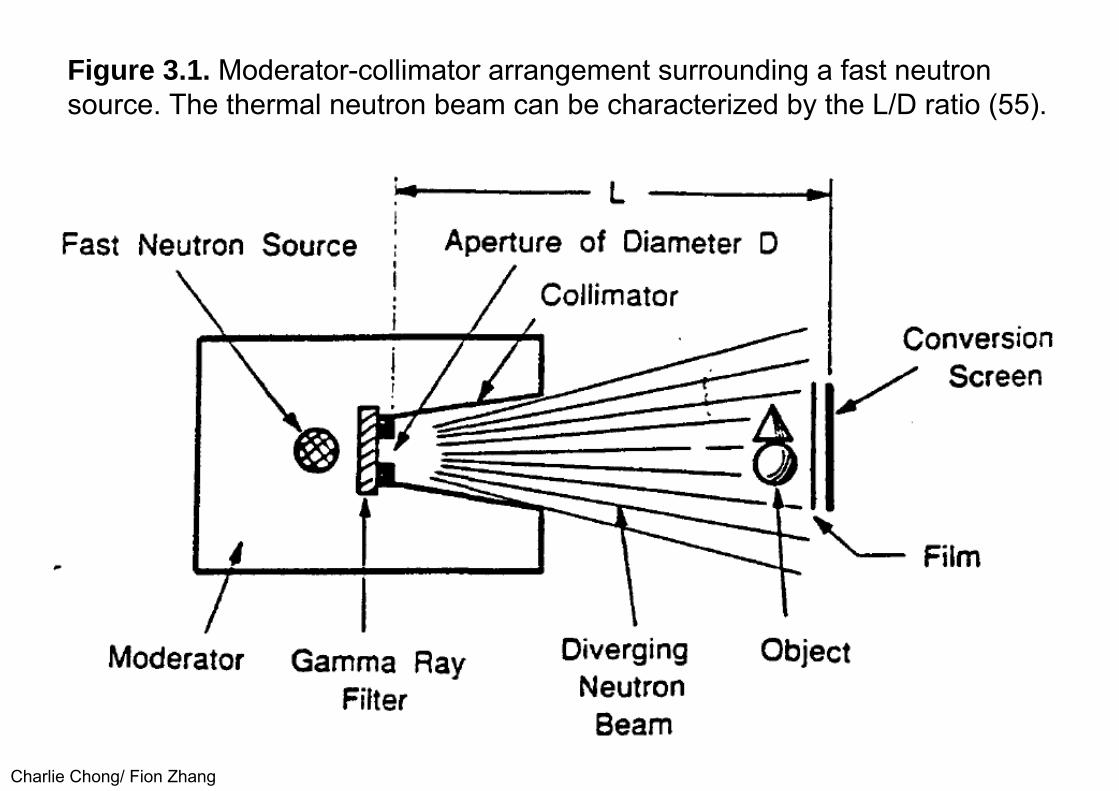
Charlie Chong/ Fion Zhang
Figure 3.1. Moderator-collimator arrangement surrounding a fast neutron source. The thermal neutron beam can be characterized by the L/D ratio (55).

Charlie Chong/ Fion Zhang
3.2 CollimationWhen thermal neutrons exit from a moderator, they are in random motion. Radiography requires that the paths of the radiation particles be as parallel toone another as is possible. Collimation is used to remove neutrons from thebeam that are not traveling in nearly parallel paths. If fast neutrons are beingused for radiography, no collimation may be needed, assuming the sourcesize is small, i.e., the target of an accelerator, approximating a point source.The methods that have been used for producing useful thermal neutronbeams are (1) the straight wall collimator, (2) the Soller slit method (a seriesof small tubes to help make the beam parallel) and (3) the divergentcollimator. Most neutron radiography is done with divergent collimators, asshown in Figure 3.1.

Charlie Chong/ Fion Zhang
Also shown in the diagram are the exit aperture for the beam, D, and the distance of the aperture to the detection plane, L. The ratio of these twodimensions, L/D, is used to define the degree of collimation in the neutronbeam. The higher that ratio, the better the beam will be for producingradiographs with good definition or sharpness. One can think of D somewhatas the focal spot of an x-ray tube. For example, it is not unusual to use an x-ray machine with a focal spot of 2mm to take radiographs at a source-to-filmdistance of 1m. This would be equivalent to a neutron beam L/D of 100 cm/0.2cm, or 500.
Reactor based neutron radiography facilities typically may use a beam L/D of about 100. An isotope or accelerator source may use a beam L/D of 30. The L/D ratio is further discussed in an ASTM standard (56). The standard also describes a method to determine the value of L/D by observing the shadow of test object removed from the detection plane.

Charlie Chong/ Fion Zhang
Equations that are used to calculate the effectiveness of the collimators are given below (36):Geometric unsharpness (Ug) for relatively thin specimens close to the image plane:
Ug = DT/L Eqn. 3.1
Where: T is specimen thicknessD is collimator aperture diameter (circular)L is length of collimator or distance from aperture to the image plane
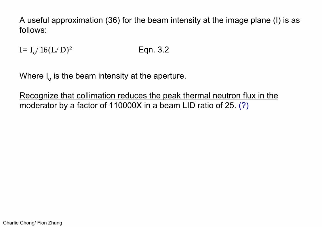
Charlie Chong/ Fion Zhang
A useful approximation (36) for the beam intensity at the image plane (I) is as follows:
I= Io/16(L/D)2 Eqn. 3.2
Where Io is the beam intensity at the aperture.
Recognize that collimation reduces the peak thermal neutron flux in the moderator by a factor of 110000X in a beam LID ratio of 25. (?)

Charlie Chong/ Fion Zhang
3.3 Nuclear ReactorsAs mentioned previously, nuclear reactors are the most expensive sources of neutrons. They also produce the largest neutron fluxes. The neutron flux atthe film plane may be 100 to 1000 times the neutron flux available fromtypical isotope or accelerator sources. This high flux, 107 to 1 08ncm-2s-1,translates into improved resolution and shorter exposure times. Reactors mayalso yield neutron beams with a high ratio of thermal neutrons to higherenergy neutrons than most other sources as well as a high ratio of thermalneutrons to gamma radiation. High thermal neutron and low gamma radiationcontent in the neutron beam tend to improve the quality of the neutronradiograph in most circumstances. The higher neutron flux of the reactorallows improvement in the collimation of the neutrons without excessiveexposure time penalties.
Because of the high cost of the nuclear reactor, few reactor facilities are devoted to neutron radiography alone. Most neutron radiographic facilitiesusing nuclear reactors are research reactors established for other purposes.The arrangements made at a research reactor to provide high quality thermalneutron beams for research in scattering, nuclear absorption, diffraction, etc.make the reactors useful as neutron radiography facilities.

Charlie Chong/ Fion Zhang
Addition of the neutron radiographic capability to the reactor rarely interferes with the original missions of the reactor facility and consumes an insignificant fraction of the neutrons available. Most research reactors include a means for bringing a thermal neutron beam from in or around the reactor core to a point outside the reactor's biological shield. The core is the arrangement offissionable fuel such as U-235, control rods (devices that absorb thermal neutrons which may be moved in and out of the core volume), and a moderator. The moderator is a material such as water, heavy water, or graphite that slows fast neutrons produced by fission of the fuel into thermal neutrons that may initiate another fission. The core may be surrounded by a "reflector“ that returns many of the high energy neutrons to the core. The neutron beam may be extracted from a point inside the core, outside the core, or in the reflector region. As the point of extraction for the beam is moved away from the inside of the core, the neutron flux available decreases but the ratio of thermal to higher energy neutrons increases. (as it is cooler)
Charlie Chong/ Fion Zhang
Shutters to stop the neutron beam as well as gamma radiation filters (a material that has high absorption for gamma rays but low absorption forthermal neutrons such as a bismuth plug) are generally provided in or at theend of the biological shield. Neutron collimators may be placed in thebiological shield or in the neutron beam after it emerges from the biologicalshield. Figure 3.2 illustrates an example of a research reactor neutronradiographic facility (57).
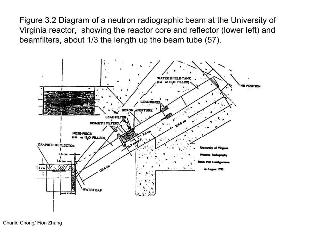
Charlie Chong/ Fion Zhang
Figure 3.2 Diagram of a neutron radiographic beam at the University of Virginia reactor, showing the reactor core and reflector (lower left) and beamfilters, about 1/3 the length up the beam tube (57).
Charlie Chong/ Fion Zhang
3.4 Accelerator SourcesIn Section 2.4, accelerator sources were described as having lower neutron outputs than reactors but having the advantages of transportability and theability to be turned off and on with little or no radiation present when turned off.The more transportable machines offer somewhat lower neutron yields thanthe larger built-in-place machines. The smaller machines also make use ofhigh yield reactions such as (d,T) which produce high energy neutrons. Thehigh energy neutrons are more difficult to thermalize and may result inneutron beams having poor thermal to high energy neutron ratios. Suchmixed neutron beams generally are not desirable for the best neutronradiographic imaging but occasionally offer some advantages.

Charlie Chong/ Fion Zhang
One of the more common accelerators used for neutron production is the Cockcroft-Walton accelerator (43, 44, 45). The Cockcroft-Walton design usesa circuit in which a set of capacitors are charged in parallel during one half ofan alternating current cycle. During the second half of the alternating currentcycle, the set of capacitors are switched from parallel to a series connectionto achieve an accelerating voltage that is a multiple of the alternating currentcharging voltage. Accelerating voltages of 100 to 400 ke V are often producedin this fashion and are sufficient to produce neutrons by either the (d,D) or(d,T) reactions. Figure 3.3 is a photograph of a transportable Cockcroft-Walton type of accelerator, shown in the process of a field inspection ( 44, 58).
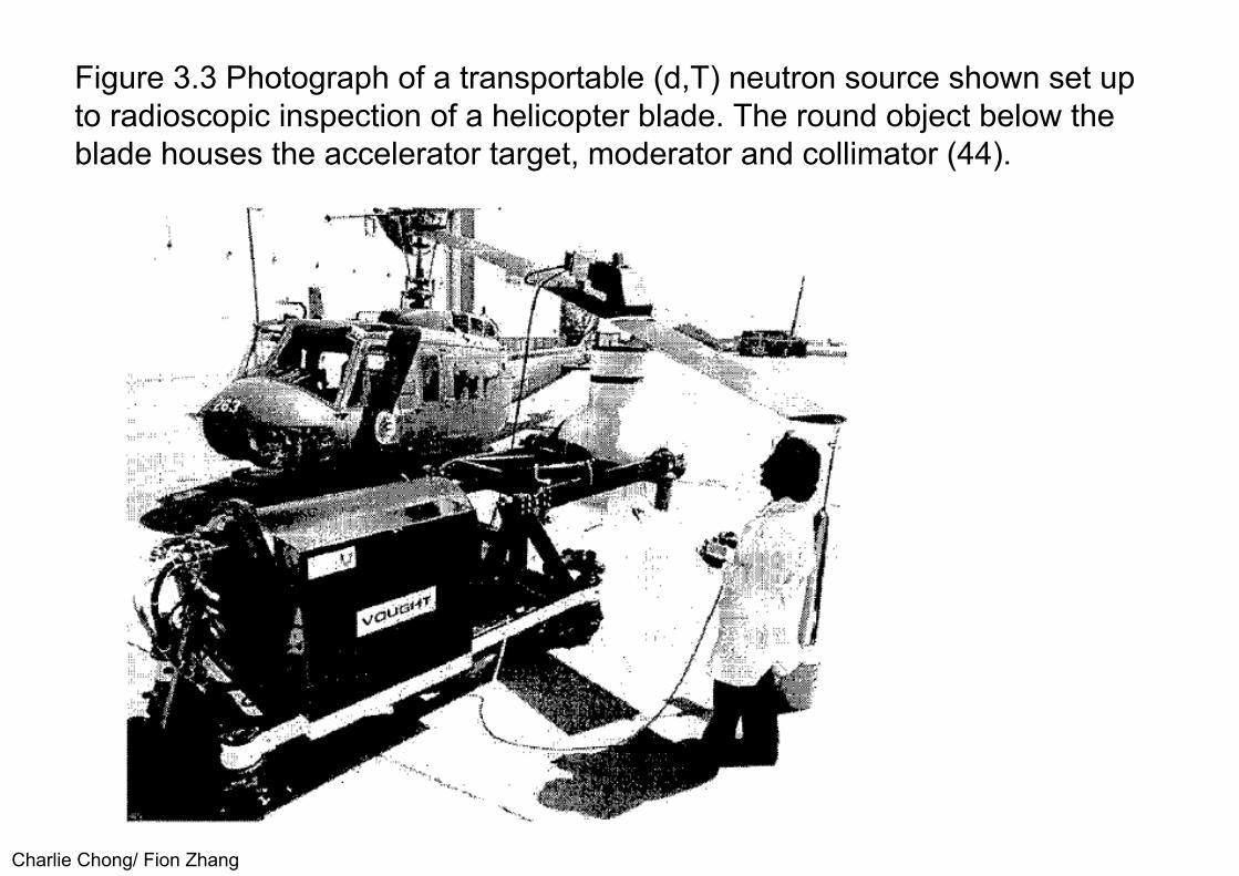
Charlie Chong/ Fion Zhang
Figure 3.3 Photograph of a transportable (d,T) neutron source shown set upto radioscopic inspection of a helicopter blade. The round object below theblade houses the accelerator target, moderator and collimator (44).

Charlie Chong/ Fion Zhang
Cockcroft-Walton Accelerator
https://share.sandia.gov/news/resources/news_releases/sandia-adopts-new-agreement-forms-to-allow-universitiesindustry-to-use-facilities/

Charlie Chong/ Fion Zhang
The (d,D) reaction produces neutrons with an energy of about 2.5 MeV at lowaccelerating voltages. At high accelerating voltages, some of the additionalaccelerating energy increases the resultant neutron energy. Neutron yieldalso increases for the ( d,D) reaction as the accelerating voltage is increased.
The (d,T) reaction produces 14.3 MeV neutrons at the threshold acceleratingvoltage of about 120 keV. Increases in the accelerating voltage only increasethe neutron yield slightly (mostly a function of the tritium target thickness andmaterial) and the neutron yield decreases with increases in accelerating voltage above about 500 keV. While the neutron yield from the (d,T) reaction is 60 times that of the (d,D) reaction, thermal neutron flux fails to increase bythe same factor because the 14 MeV neutrons are so much more difficult tothermalize. Another disadvantage to the ( d, T) reaction is that the neutronyield decreases with target use time because the tritium is being depletedboth by the nuclear reaction and by heating of the target.
Charlie Chong/ Fion Zhang
The heating of the target releases quantities of the tritium (radioactive hydrogen) into the vacuum system and finally into the atmosphere in pumped, non-sealed systems. Most modern (d,T) neutron sources make use of sealed tubes, which eliminate many of the tritium handling problems. Life-times of sealed (d,T) neutron tubes approach 4,000 hours before the neutron yield is reduced to half that at maximum neutron yield (58, 59).
Charlie Chong/ Fion Zhang
Small Van de Graaff accelerators have been used for neutron radiography (24, 49, 60, 61). The accelerating potential in a Van de Graaff accelerator isproduced by placing an electrical charge on a moving, non-conductor belt,removing the charge\.from the belt at a distance from the charging point, andstoring the charge on a smooth, almost spherical metal surface. Extremelyhigh voltages can be created in this fashion which permits a variety of othernuclear reactions to be used to produce neutrons. A diagram of a Van deGraaff accelerator is shown in Figure 3.4. Some examples of neutronproducing nuclear reactions used in Van de Graaff accelerators are theacceleration of 1H+ protons or 2H+ deuterons into beryllium 4Be, protons into lithium-7, deuterons into carbon-12, and deuterons into either deuterium or tritium targets. Most of the Van de Graaff accelerators used for neutron radiography are large systems set up for other purposes such as research in nuclear physics.

Charlie Chong/ Fion Zhang
Van de Graaff Accelerators

Charlie Chong/ Fion Zhang
Van de Graaff Accelerators

Charlie Chong/ Fion Zhang
Figure 3.4. Diagram of a Van de Graaff accelerator, showing how the charges are moved along the belt to build up a high voltage charge (19).

Charlie Chong/ Fion Zhang

Charlie C
hong/ Fion Zhang

Charlie Chong/ Fion Zhang
Linear accelerators are also useful sources for neutron radiography. Some early work was done with a LINAC x-ray source, the high energy x-rays being used to produce neutrons from an (x,n) reaction in a beryllium target (62). An x-ray intensity of 650 R/minute at 1 meter resulted in a thermal neutron beam of 5 x 10⁴ n∙cm-2s-1 , with fair collimation. The x-ray method for producing neutrons may be important for inspection facilities that have a high energy x-ray source and need neutron radiographic capability only rarely. Nevertheless, the intense x-ray background makes neutron radiography difficult.
New accelerators, using radio frequency quadrupole techniques are now available (28, 30, 63), offering a range of neutron outputs, up to neutronradiographic beam intensities in the order of 106 n∙cm-2s-1 with excellentcollimation (L/D values of 100). These accelerators typically use a neutronreaction of protons or deuterons on a beryllium target to produce fastneutrons of a few MeV in energy. Recent work has shown that these long,high output accelerators might be adapted as transportable neutronradiography sources, as shown in Figure 3.5 (63).

Charlie Chong/ Fion Zhang
Figure 3.5 Drawing of a design for a transportable RFQ accelerator neutronsource. Note the accelerator length on the bottom scale, 9 m (63).

Charlie Chong/ Fion Zhang
Cyclotrons also have been used for neutron radiography. Compact units can produce high neutron yields into moderator-collimator assemblies, for intensethermal neutron radiography beams (47, 64, 65). A cryogenically cooledcyclotron, accelerating 12 MeV protons on a beryllium target, has been usedfor thermal neutron radiography, with beam intensities of 7.3 x 10⁵n cm-2 s-1 at an L/D of 100 (28, 47). A conceptual drawing of such a cyclotron neutronradiography source as a transportable system is shown in Figure 3.6 (65).New high voltage machines sources accelerating high energy protons canproduce intense neutron yields by the spallation process. A large, expensivemachine (590 MeV) designed for nuclear research is now being used forneutron radiography, as indicated earlier in Section 2.4 ( 48).

Charlie Chong/ Fion Zhang
Figure 3.6 Artist drawing of a transportable cyclotron neutron radiographysource (65).

Charlie Chong/ Fion Zhang
3.5 Radioisotope Neutron SourcesNo radioisotope of the 92 elements occurring in nature emits neutrons. Neutron emission is produced by combining radioisotope sources with targetmaterials or by making a transuranic radioisotope like Californium-252 whichdecays by spontaneous fission. The more common radioisotope neutronsources are combinations of alpha emitting radioisotopes such as Polonium-210, Americium-241, or Plutonium-239 with beryllium. The alpha particleinteracts with the beryllium to release a neutron while forming an atom ofcarbon-12. The combination of the radioisotope and beryllium must be verywell mixed very fine powders of each material because of the short range ofthe alpha particle. Preparation of mixtures of such fine powders of two toxicsubstances must be carried out with great care. The mixture is placed instainless steel capsules that are welded closed. In some cases, theradioactive mixture is double encapsulated. The resultant source is typically aright circular cylinder about 1 inch in diameter and 1 inch tall. Each of thealpha emitting radioisotopes listed above will produce about 2 X 10⁶ n/sec per curie of activity when mixed with beryllium.

Charlie Chong/ Fion Zhang
The Californium-252 neutron source spontaneously fissions and therefore does not have to be mixed with a target material, such as beryllium. Astainless steel encapsulated Cf-252 source emitting 109 n/sec would onlycontain 1 milligram of the radioisotope and would be about 1.27 cm indiameter and 3.81 cm long (0.5 X 1.5 in.) Size of the capsule is convenient forfabrication, durability, and handling and changes little for much largerquantities of the radioactive material. The Cf-252 is made by multiplesuccessive neutron captures in Uranium-238 in very high neutron flux nuclearreactors. The Cf-252 is removed by chemical separation from the mixtures ofmaterials formed. Even with such an expensive production technique, cost ofthe Cf-252 has been in the range of $10 to $20 per microgram (2.3 X 10⁶
n/sec per microgram.) However, encapsulation and transportation chargescan vastly overshadow the isotope cost. Radioisotope neutron sources wouldbe far too bulky and expensive for use as sources for quality neutronradiography which normally requires approximately 1010 fast n/sec forreasonable thermal beam intensities. The radioisotope sources can produceneutron radiographs in circumstances where portability and lack of externalpower are important and radiographic quality need not be the best.
Charlie Chong/ Fion Zhang
3.6 Sub-critical AssembliesSub-critical assemblies combine the production of neutrons by a fast source such as Cf-252 with some neutron multiplication by U-235 fission such as exists in a nuclear reactor. The multiplication is kept below what is necessary for a self-sustaining fission reaction. These assemblies Increase the neutron yield from a given source by factors as high as 30 but lose the portability of the radioisotope source and become fixed in place sources. The sub-critical assemblies do not require the safety features and additional licensing and personnel required by a reactor but they also do not provide the high neutron output available from a reactor. As indicated in Section 2.4, a fixed sub-critical neutron source was used extensively for radiography at the MoundLaboratory in Ohio, until closed down in the early 1990's (51,52). Development that placed fissionable materials within the moderator assembly of an accelerator source has also been reported (67), the end result being an increase in the available neutrons by a factor of 1.5.
Charlie Chong/ Fion Zhang
4.0 NEUTRON IMAGING TECHNIQUES4.1 Indirect or Transfer Imaging TechniquesIn Section 2.5, the process of indirect or transfer neutron radiography was very briefly described. This technique provides some of the more unusual advantages of neutron radiography such as radiography of highly radioactive specimens. The technique also permits discrimination of the type of radiation being imaged; i.e., neutrons versus gamma radiation or one energy range of neutrons versus other energy ranges of neutrons (?).

Charlie Chong/ Fion Zhang
spatial resolutionvalue of 50-100μm
The contrast sensitivity for 25 mmsteel or uranium objects is 4~6%.
Typical screen LiF-ZnS and gadolinium oxysulfide
105 n∙cm-2 (film)3 x 10⁶ n∙cm-2s-1
(30 frames/s)
Scintillators Method
spatial resolutionvalue of 25μm
The contrast sensitivity for 25 mmsteel or uranium objects is 1%.
Typical screen Li or B
109 n∙cm-2
spatial resolutionvalue of 10μm
The contrast sensitivity for 25 mm steel or uranium objects is 2%.
Typical screen Gd, Li
109 n∙cm-2
25μm thick
spatial resolutionvalue of 50μm
The contrast sensitivity for 25 mm steel or uranium objects is 1%.
Typical screen In, Dy
104 n∙cm-2 minimum
?μm thick
Track-EtchedDirect Gadolinium Method
Transfer Method
Charlie Chong/ Fion Zhang
Indirect or transfer neutron radiography is performed by exposing an imaging screen to the neutrons transmitted through the specimen without film beingpresent. These imaging screens become radioactive by interaction with theneutrons; a radioactive "image" is formed on the screen by the neutronstransmitted through the specimen. When sufficient radioactivity has beeninduced in the screen, exposure to the neutrons is ended and the screen istransferred to a cassette containing film (done in a non-radiation area). SeeFigure 2.1.
The radioactivity in the screen is allowed to decay for a period of time sufficient to expose the film (usually not more than 3 half life, 3 x T½ ) . Good contact between the screen and the film is essential for good quality image production. Major exposure to the film is by beta particles from the decaying radioisotope in the screen. In a few instances, the radiation emitted may be weak gamma radiation from isomeric transitions or x-rays which follow electron capture. Table 2.2 includes a listing of screens used for the indirect or transfer technique.
Film activating agents: Beta, gammas, x-ray, (conversion electron?)

Charlie Chong/ Fion Zhang
Production of the radioactive species in the screen (sometimes referred to as 'foil' since they are usually very thin metal sheets) can be described by the equation:
A = NσΦ(1 - e -0.683t/T) (Eqn. 4.1)
A is the activity produced in disintegrating atoms/secondN is the number of target atoms per cm3 in the specimenσ is the cross section of the target atom in cm2
Φ is the neutron flux in n∙cm-2 sec-1
t is the neutron exposure timeT is the half life of the isotope produced.
At the moment that neutron exposure is discontinued, the radioactive isotopes in the screen decay according to:
A’ = Aoe -0.683t/T (Eqn. 4.2)
A’ is the activity remaining after decay time t or the time from end of activation to measurement.Ao is the activity at the end of neutron exposure.

Charlie Chong/ Fion Zhang
Notice should be taken that the quality of the image on the screen will be a function of the usual radiographic parameters such as:
1. source size, 2. source-to-film distance,3. thickness of the specimen,4. closeness of the specimen to the detector as well as 5. other geometric factors, 6. scatter of the radiation in the specimen and around the screen plus7. neutron absorption characteristics of the specimen versus its flaws and 8. the statistics of radiation decay and detection.
Section 2 contains ( information on the factors affecting neutron absorption, in the specimen (especially cross section). Information on the details of radioactive decay and detection statistics can be found in nuclear science or nuclear engineering books (39, 40, 67). It is sufficient here, to note that the quality of the image obtained from the screen will be dependent upon the amount of the radioisotope produced in the screen. Better images are obtained by producing more radioactivity in the screen.
Charlie Chong/ Fion Zhang
Equation 4.1 then predicts that exposure or activation time improves the quality of the image only initially. After several half lives in exposure oractivation time, the radioactivity in the screen reaches saturation (no longerincreases) and longer neutron exposure does not improve image quality. Forexample, a period of 3 half-lives produces 87.5% of the possible activation orautoradiographic exposure that can be obtained. Improvements in the imagequality must then come from larger neutron fluxes or use of screens havingtarget atoms with a greater cross section for neutron reaction. Typical screenmaterials used for the transfer method include indium (54.1 minute half-life)and dysprosium (140 minute half-life).

Charlie Chong/ Fion Zhang
Note that in the same fashion, exposures of the screens to film longer than a few half lives do not materially improve the image quality because there islittle radioactive decay of the desired radioisotope remaining.
Also note that using thicker screens to increase the number of target atoms reduces image quality from geometric and scatter factors and may result in some absorption of the radioactive emission within the screen. Screen thicknesses of about 0.010 inch for indium and 0.005 inch for dysprosium are close to the saturation limit in terms of film density (12). If high neutron flux is not available, the choice is then usually to change from indirect imaging to direct imaging or to another technique such as track-etch imaging.

Charlie Chong/ Fion Zhang
Track-etch techniques produce insulating material films with damage tracks that can be chemically etched to disclose an image ( 68). Typical materials forthermal neutron radiography include an alpha emitter, such as lithium orboron, used with a cellulose nitrate film. The alpha particles produced uponneutron absorption damage the plastic. A chemical etch, typically 30 minutesin a potassium or sodium hydroxide solution, reveals the pattern of small etchholes (69). The image can be observed or photographed by a side-lightmethod.
There are many advantages of track-etch: ( 1) easy handling of films in the light, (2) response to thermal neutrons and not to gamma rays, (3) linear response over several orders of magnitude of exposure, (4) excellentresolution because of the short range of the alpha particle and (5) exposureas long as needed for a useful image.
For the application to neutron radiography of radioactive materials (69), tracketch methods eliminate exposure problems that might result from low neutron flux, as is true for the transfer film method. Exposures can be as long as necessary. Exposures in the order of 109n/cm2 are usually used for track-etch thermal neutron images.

Charlie Chong/ Fion Zhang
4.2 Direct Neutron ImagingDirect neutron imaging describes the simultaneous use of a neutron converter screen and film in the neutron beam (see Figure 2.1.) The screen isnecessary to convert the neutrons into a more detectable radiation to exposethe film. In this case, longer exposure times should materially improve theradiographic image on the film. The radiation detected by the film is mostusually prompt radiation or radiation that is released by the target atomimmediately after neutron interaction ·rather than being released by the decayof a radioactive species. In fact, the neutron interaction need not produce aradioactive product so long as the neutron reaction involves release of someradiation detectable by the film.
Keywords:Prompt radiation: radiation that is released by the target atom immediately after neutron interaction ·rather than being released by the decay of a radioactive species.

Charlie Chong/ Fion Zhang
Since decay of a radioactive species is not usually a strong contribution to the image production, the radiation contributing to the image is represented by:
A = NσΦt (Eqn. 4.3)
A is the activity produced in disintegrating atoms/secondN is the number of target atoms per cm3 in the specimenσ is the cross section of the target atom in cm2
Φ is the neutron flux in n∙cm-2 sec-1
t is the neutron exposure timeT is the half life of the isotope produced.

Charlie Chong/ Fion Zhang
The conversion screen most used for direct thermal neutron radiography is gadolinium, a very high cross section material (see Table 2.2). Since thermalneutron absorption is so high in this material, it is feasible to use a very thinscreen, 0.001 inch (25.4μm) or less. For optimum results a single conversion screen is used in back of the film.
The neutron reaction with this material produces an internal conversion electron, of energy about 70 keV, radiation that is easily detected by an x-ray film. The high detection efficiency and the short range of the emitted electron result in neutron radiographs of excellent quality. Spatial resolution values of 10 microns have been reported (70). Fine grain, single emulsion films are often used with a gadolinium screen to produce high quality thermal neutron radiographs; exposure needed is in the order of 109 n∙cm-2. Faster film results can be obtained by using faster films with a single or multiple gadoliniumscreens or by light-emitting screens with a fast light- sensitive film. A Li6F-ZnS scintillator with a fast film can provide useful results with much faster exposures, in the range of 105 n∙cm-2s-1 (105 n∙cm-2 ?) .

Charlie Chong/ Fion Zhang
Gadolinium Direct method: exposure needed is in the order of 109 n∙cm-2. Scintillator Li6F-ZnS scintillator Direct method: exposure need 105 n∙cm-2s-1.
Real Time Imaging-Scintillator methodFor good image quality, one seeks to have a neutron exposure per image of about 105 ncm-2. For a typical television system showing images at the rate of 30 frames/s, this means that a neutron source that supplies a beam intensity of 3 x 10⁶n cm-2s-1 will provide good quality, real-time images.

Charlie Chong/ Fion Zhang
A summary of the characteristics of film exposures, both direct and transfer types may be useful. The transfer films have the advantage of having noresponse to gamma radiation, an advantage that often results in improvedcontrast (contrast sensitivity) . Exposures tend to be longer than directexposures because two exposures are needed. Spatial resolution is good, inthe range of 50 microns, but not quite as good as can be achieved with thedirect method using a gadolinium screen.
Direct film methods can be obtained with only one exposure, so an image canusually be viewed in less time. Also, as noted, direct exposures with a singlegadolinium screen can yield neutron radiographs that display detail as smallas 10 microns (spatial resolution) .
Track-etch methods offer insensitivity to gamma radiation, good resolution, wide dynamic range and exposures as long as needed for a useful image.
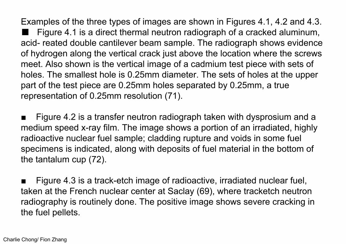
Charlie Chong/ Fion Zhang
Examples of the three types of images are shown in Figures 4.1, 4.2 and 4.3.■ Figure 4.1 is a direct thermal neutron radiograph of a cracked aluminum, acid- reated double cantilever beam sample. The radiograph shows evidence of hydrogen along the vertical crack just above the location where the screwsmeet. Also shown is the vertical image of a cadmium test piece with sets ofholes. The smallest hole is 0.25mm diameter. The sets of holes at the upperpart of the test piece are 0.25mm holes separated by 0.25mm, a truerepresentation of 0.25mm resolution (71).
■ Figure 4.2 is a transfer neutron radiograph taken with dysprosium and a medium speed x-ray film. The image shows a portion of an irradiated, highly radioactive nuclear fuel sample; cladding rupture and voids in some fuel specimens is indicated, along with deposits of fuel material in the bottom of the tantalum cup (72).
■ Figure 4.3 is a track-etch image of radioactive, irradiated nuclear fuel, taken at the French nuclear center at Saclay (69), where tracketch neutron radiography is routinely done. The positive image shows severe cracking in the fuel pellets.

Charlie Chong/ Fion Zhang
Figure 4.1 Direct thermal neutron radiograph taken with a gadolinium screenshowing a cracked double cantilever beam aluminum sample. Hydrogendeposits along the vertical crack above the location where the screws meet isevident. The cadmium test bar at the left shows images of many small holes,including the sequence at the top, 0.25mm holes spaced 0.25mm apart (71).
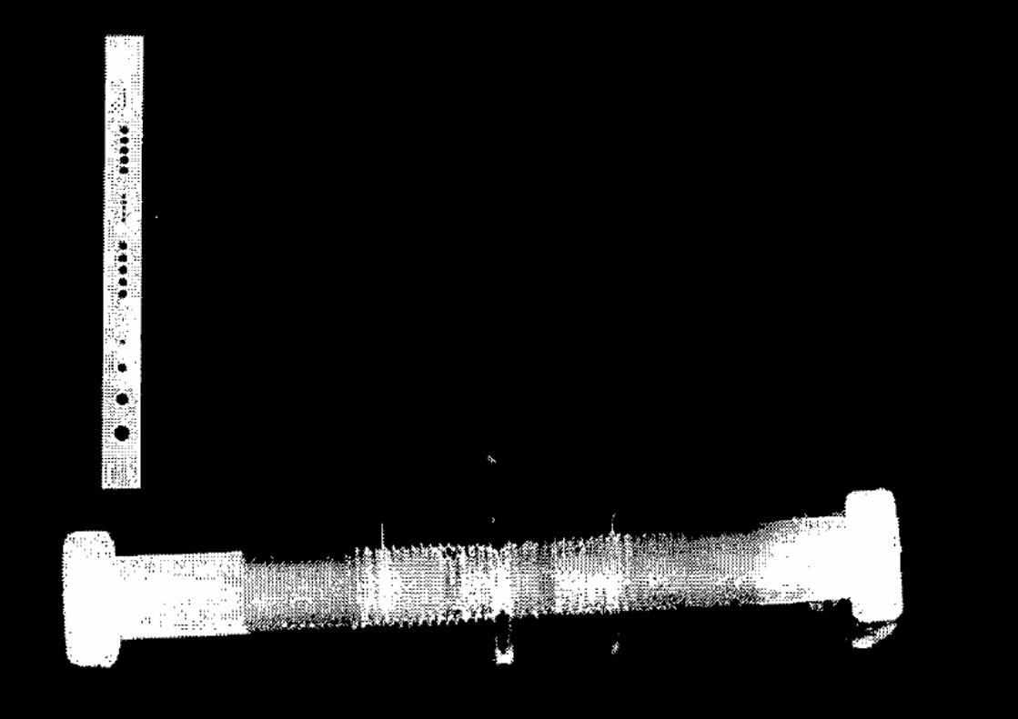
Charlie Chong/ Fion Zhang

Charlie Chong/ Fion Zhang
Figure 4.2. A transfer thermal neutron radiograph of irradiated nuclear fuelshows cladding rupture and fuel deposits in the bottom. Image taken with anindium transfer screen (72).

Charlie Chong/ Fion Zhang
Figure 4.3 A track-etch neutron radiograph of nuclear fuel, showing extensive cracking (69).
Charlie Chong/ Fion Zhang
4.3 Radioscopy (Real Time Imaging)Figure 4.3 A track-etch neutron radiograph of nuclear fuel, showing extensivecracking (69). Neutron radioscopic systems can provide real-time imageswhile the neutron exposure is occurring. The systems may incorporate aneutron conversion screen in an image intensifier tube. Screens of LiF–ZnSand gadolinium oxysulfide have been used in neutron image intensifier tubes.In addition, as discussed briefly in Section 2.5, these light-emitting screensmay be used with a mirror-lens-camera system (28, 29, 30, 47, 48, 57, 73), asshown in Figure 2.2. Boron nitride scintillators have also been investigated forboth film and camera imaging but thus far have seen little application (74, 75).Other solid state camera systems, GaAs arrays, for example, have also beeninvestigated for neutron radioscopic imaging (76). These systems mayprovide very fast imaging with high neutron flux sources so that motion of thespecimen can be observed.
Keywords:LiF-ZnS, Gadolinium-oxysulfideBoron Nitride, GaAs

Charlie Chong/ Fion Zhang
For good image quality, one seeks to have a neutron exposure per image of about 105 n cm-2. For a typical television system showing images at the rate of 30 frames/s, this means that a neutron source that supplies a beam intensity of 3 x 10⁶ n∙cm-2s-1 will provide good quality, real-time images.
Useful neutron radioscopic images can be obtained with lower neutron beamintensities, but one may have to use a slow scan technique, say 5 or 10frames/s, or make use of images with more noise. Recognize that anexposure of 105 n∙cm-2s-1 will result in images with some quantum noise, that is noise due to fluctuations in the neutron beam itself (28, 70).

Charlie Chong/ Fion Zhang
A diagram of a typical screen-CCD camera system was shown in Figure 2.2. Neutron image intensifier tubes are commercially available, with a 9-inch diameter input screen. Neutron radioscopic methods have been used in high through- ut inspection of aircraft to detect corrosion (28, 29) and to image dynamic events to investigate object movements during a process. Forexample, a reactor pulse has been used to perform fast neutron imaging of explosive firing and to observe two-phase flow, at frame rates up to 10,000 frames/s (77). At more conventional, 30 frames/s rates, dynamic neutron imaging has been used to follow movement of fluids in engines and transmissions (78, 79), to observe coking in engine nozzles (80, 81) and to observe movement of moisture (82).
Charlie Chong/ Fion Zhang
An example of a dynamic thermal neutron image sequence is shown in Figure 4.4 (total time from image 1 to the end is 0.66 seconds). Image 1 shows the start of a pour of Wood's metal into an aluminum mold. It can be seen in frames 6 and 7 that the vertical riser of the mold begins to fill before the vertical leg of the casting below. This poor casting design will lead to porosity in the casting (34).
The applications cited provide evidence for the usefulness of neutron radioscopic methods.
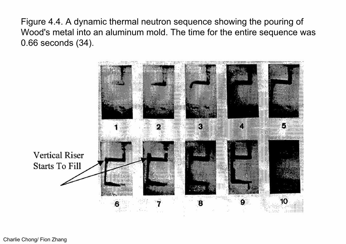
Charlie Chong/ Fion Zhang
Figure 4.4. A dynamic thermal neutron sequence showing the pouring ofWood's metal into an aluminum mold. The time for the entire sequence was0.66 seconds (34).
Charlie Chong/ Fion Zhang
4.4 Neutron Computed TomographyJust as X-ray and gamma ray radiography have found use in computed tomography (CT) applications (83 ), neutron tomography has been used toprovide important information. The ASTM standard cited (83) is a CT tutorialdocument that includes a glossary of terms and an extended list of references.The image produced in a conventional radiograph is a shadow image of thespecimen's density and thickness, whereas a tomographic image is a crosssectional image (a slice) of the specimen parallel to the radiation beam. Inaddition, this slice is essentially free from features in other object slices orplanes, unlike a conventional radiograph which shows a superposition of allplanes in the image.
Charlie Chong/ Fion Zhang
CT can be accomplished by passing a thin, wide beam (often called a "fan" beam because of its shape) of radiatipn through the slice of the specimen tobe imaged, or in more recent developments, using conventional cone beam techniques. The radiation is detected by a line or row of detectors, or by an area imager, on the opposite side of the specimen. For the fan beam approach, the specimen, or the source-detector assembly, is rotated so that the specimen is examined with the radiation beam passing through all segments of the specimen (usually 180 degrees of rotation.) In some cases, the specimen may be moved laterally through the beam between rotations. In the case of the cone beam method, the object can be rotated in the beam to collect the required number of views. A computer then reconstructs a cross sectional image of the specimen from the thousands of individual absorptionmeasurements made through the specimen. Neutron CT imaging has been applied to a wide range of applications including nuclear fuel (84), aircraft components, material testing and archeology applications (85, 86, 87).

Charlie Chong/ Fion Zhang
4.5 Other Neutron Imaging TechniquesImage detection methods for neutrons other than thermal are available. Cold neutrons and near epithermal neutrons can be detected by methods similar tothose described for thermal neutrons. In addition, there are materials whichexhibit resonances at selected neutron energies that can be used to detectneutrons in the near epithermal energy range. For example, indium exhibits alarge activation resonance at an energy of 1.46 e V. This transfer imagemethod has been used for neutron radiography of nuclear fuel to obtainimproved transmission of these higher-than-thermal energy neutrons. Anexample is shown in Figure 4.5. The transfer neutron radiographs ofirradiated fuel were taken with thermal neutrons for the view on the left. Thehigh neutron absorption of the enriched fuel results in sharp edges which areuseful for dimensional measurements. The resonance neutron radiograph onthe right, taken by filtering the beam through cadmium to remove thermalneutrons before the neutrons strike the indium screen, shows much improvedtransmission through the fuel so internal details can be seen (70).
Keywords:Cold neutron, near epithermal neutron, large activation resonance

Charlie Chong/ Fion Zhang
Figure 4.5. Transfer neutron radiographs of irradiated, enriched nuclear fuel. The view at the left was taken with thermal neutrons for dimensionalmeasurements. The view at the right, taken with a cadmium-filtered indiumscreen technique, shows improved penetration of the fuel to observe internalcracking and deposits (70).

Charlie Chong/ Fion Zhang
Radiography with fast neutrons has also been investigated (88, 89, 90, 91). Image detection usually depends on knock-on protons from a hydrogenousmaterial stimulating adjacent phosphor grains. The hydrogenous bindercombined in a typical phosphor screen used for x-ray imaging will provide fastneutron radiographs with film. Once a scintillator is available to emit lightwhen irradiated with fast neutrons, then a radioscopic image method can alsobe used (90, 91). Fast neutron imaging can also be done using the indirectmethods of activation transfer and track-etch (70). There are other methodsfor imaging of neutrons that should be mentioned (70). Thermoluminescentphosphors, such as LiF can be used for neutron imaging by irradiating thephosphor and then capturing the emitted light as the phosphor is heated. Aspark counter technique has been used to image neutrons, using an array ofwires and a boron screen. Neutron capture in the boron causes release of analpha particle, which ionizes the gas in the spark counter enclosure, causinga spark. A collection of spark images will produce an overall image of theincident neutron beam. Ionography, a method of making an electrostaticimage on an insulating surface by ionization caused by the radiation, hasbeen investigated for x-ray (92) and neutron imaging (93). These alternateneutron imaging methods have not been widely used.
Charlie Chong/ Fion Zhang
However, a new radiation imaging method, making use of a photostimulable luminescent (PSL) phosphor is likely to become important for both x-ray andneutron imaging. The PSL phosphor, typically a europium activated bariumfluorohalide, can be coated on a rigid or flexible substrate (94, 95, 96).Storage phosphors have been studied extensively for x-ray imaging. Thephosphors emit light that has been trapped upon radiation exposure when thephosphor image plate is irradiated with a long wavelength light, such as thatfrom a red laser. The emitted light is collected by a photomultiplier tube,whose output is correlated with the position of the laser spot to form an image.After the image is read out and displayed, the remaining signal on the imageplate is erased by exposure to white light and/or infrared. The storagephosphor process is illustrated in Figure 4.6. Storage phosphors offersensitive, wide dynamic range, digital imaging with re-usable image plates. Inaddition, no image processing chemicals are required, an advantage in termsof environmental problems.

Charlie Chong/ Fion Zhang
Figure 4.6. Diagram showing the sequence for a storage phosphor radiationimaging system.
Charlie Chong/ Fion Zhang
Thermal neutron imaging has been done with these new image plates by adding conversion screens as is done with film. Work is reported withgadolinium, lithium-6 or gadolinium oxysulfide converters (97, 98, 99).Storage phosphor techniques offer similar advantages for neutron imaging ashas been found for x-ray imaging.
Charlie Chong/ Fion Zhang
4.6 Contrast AgentsIf the specimen does not possess components that respond to neutron imaging, some components such as cracks, channels, or voids may be filledwith substances that possess large neutron attenuation cross sections. As anexample, water containing boron compounds such as boric acid or borax maybe allowed to infiltrate the features of interest. Contrast agents may be addedto the components to be imaged; i.e., boron, lithium, helium or rare earthcompounds may be added to the inspection system or in the manufacture ofmaterials such as bonding agents, "0" rings, insulators, or metallic parts sothat they can be more readily imaged. The contrast agent may be needed toutilize a lower neutron flux or to reduce exposure times, as well as to increasesensitivity of detection. Some references describing studies with neutroncontrast materials are cited (1 00, 101, 1 02). The neutron radiographicexamination of turbine blades, using gadolinium material contrast agents is awidely used example for enhanced imaging by contrast agents (103, 104), asshown in Figure 4.7 (34).
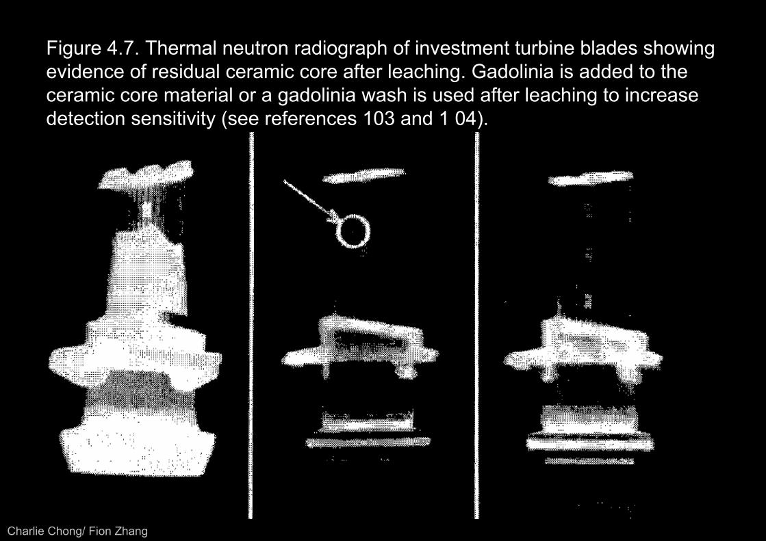
Charlie Chong/ Fion Zhang
Figure 4.7. Thermal neutron radiograph of investment turbine blades showingevidence of residual ceramic core after leaching. Gadolinia is added to theceramic core material or a gadolinia wash is used after leaching to increasedetection sensitivity (see references 103 and 1 04).

Charlie Chong/ Fion Zhang
In a few circumstances, the energy of the neutrons may be changed toincrease the relative absorption by components of a specimen.
Many elements exhibit very large resonance absorption cross sections forneutrons in the epithermal range.
By using neutron fluxes that are high in epithermal neutrons, elements and the components that contain them may be better imaged than by thermal neutron fluxes alone. Resonance absorption elements then become contrast agents for the components in which they are found, if neutron energy of the beams can be modified. In addition, as discussed earlier, epithermal neutrons may show increased penetration of materials or isotopes that strongly absorb thermal neutrons; see Figure 4.5 for an example.
Comments: How the resonance absorption is rationalizes here?

Charlie Chong/ Fion Zhang
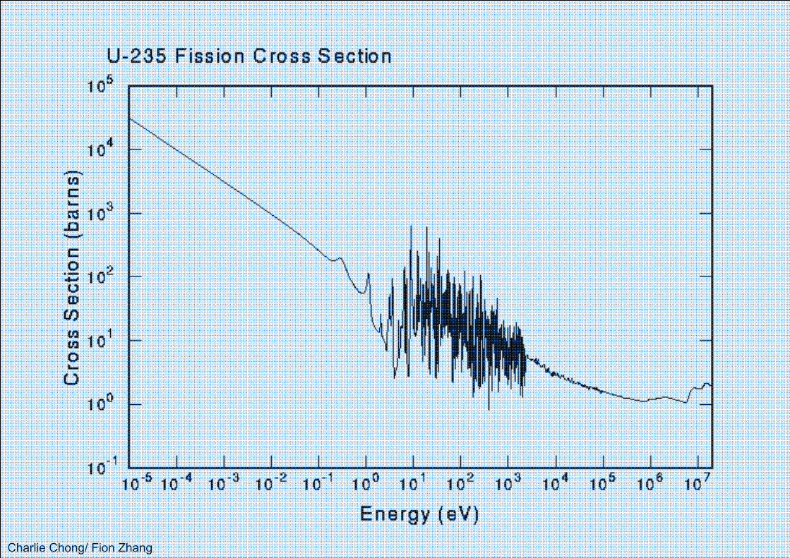
Charlie Chong/ Fion Zhang
Charlie Chong/ Fion Zhang
5.0 STANDARDS/RECOMMENDED PRACTICES5.1 SYSTEM PERFORMANCEImportant parameters of a neutron imaging system include the neutron energy spectra, the relative intensity and energy of other radiation (mainlygamma radiation and scattered radiation in the imaging beam), and thegeometric properties of the system. There are standards which address thesevariables.
Four standards for neutron radiography are available from the American Society for Testing and Materials (ASTM). Standard E 748 (55) is a tutorial document that describes the general method and provides guidance.Methods for measurement ot dimensions of objects in a neutron radiographare described in Standard E 1496 (105). Image quality measurements forthermal neutron radiographs are described in Standard E 545 (106). Thisapproach makes use of test pieces whose images on a neutron radiographcan be analyzed to determine a measure of image quality. Standard E 803(56) describes a test piece and method for measurement of the L/D ratio inneutron radiographic beams (see Figure 3.1). The L/D ratio is a determiningfactor in the sharpness of an image in a neutron radiograph.
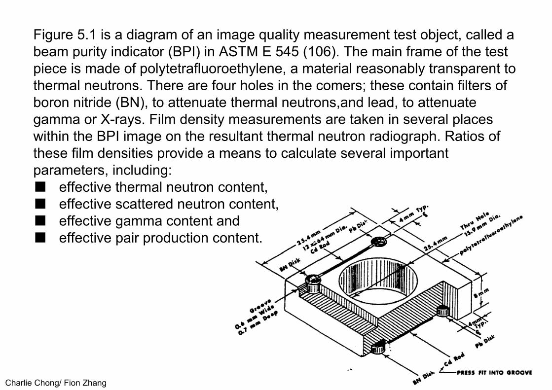
Charlie Chong/ Fion Zhang
Figure 5.1 is a diagram of an image quality measurement test object, called a beam purity indicator (BPI) in ASTM E 545 (106). The main frame of the testpiece is made of polytetrafluoroethylene, a material reasonably transparent tothermal neutrons. There are four holes in the comers; these contain filters ofboron nitride (BN), to attenuate thermal neutrons,and lead, to attenuategamma or X-rays. Film density measurements are taken in several placeswithin the BPI image on the resultant thermal neutron radiograph. Ratios ofthese film densities provide a means to calculate several importantparameters, including:■ effective thermal neutron content, ■ effective scattered neutron content, ■ effective gamma content and ■ effective pair production content.

Charlie Chong/ Fion Zhang
For example, the effective thermal neutron content involves the total filmdensity, taken in the region of the large central hole, less the film densityunder the BN filter, plus the difference in film density under the two lead filters,divided by the total film density.
Normally the effective thermal neutron content as determined in this way is in the 45%-65% range.
Similarly, there are formulas for calculating the other variables as imaged on the thermal neutron radiograph by the BPI. These measurements provide a method for comparing radiographs taken at different times or under different conditions. The measurements are influenced by the characteristics of the neutron radiographic facility as determined by the object and set-up for the particular radiograph being measured. The measurements, therefore, relate to the neutron radiograph.

Charlie Chong/ Fion Zhang
Figure 5-1. Beam purity indicator (BPI) test piece as described in ASTM E545, 1998. (From ASTM E 545, reference 106.) Reprinted with permission.
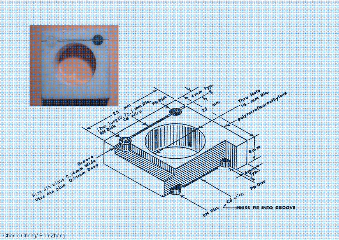
Charlie Chong/ Fion Zhang
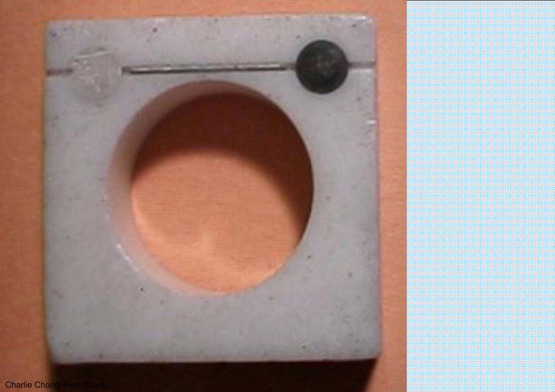
Charlie Chong/ Fion Zhang

Charlie Chong/ Fion Zhang

Charlie Chong/ Fion Zhang
DB Film densities measured through the images of the boron nitride disks.DL Film densities measured through the images of the lead disks.DH Film density measured at the center of the hole in the BPI.DT Film density measured through the image of the polytetrafluoroethylene.∆DL Difference between the DL values.∆DB Difference between the two DB values.
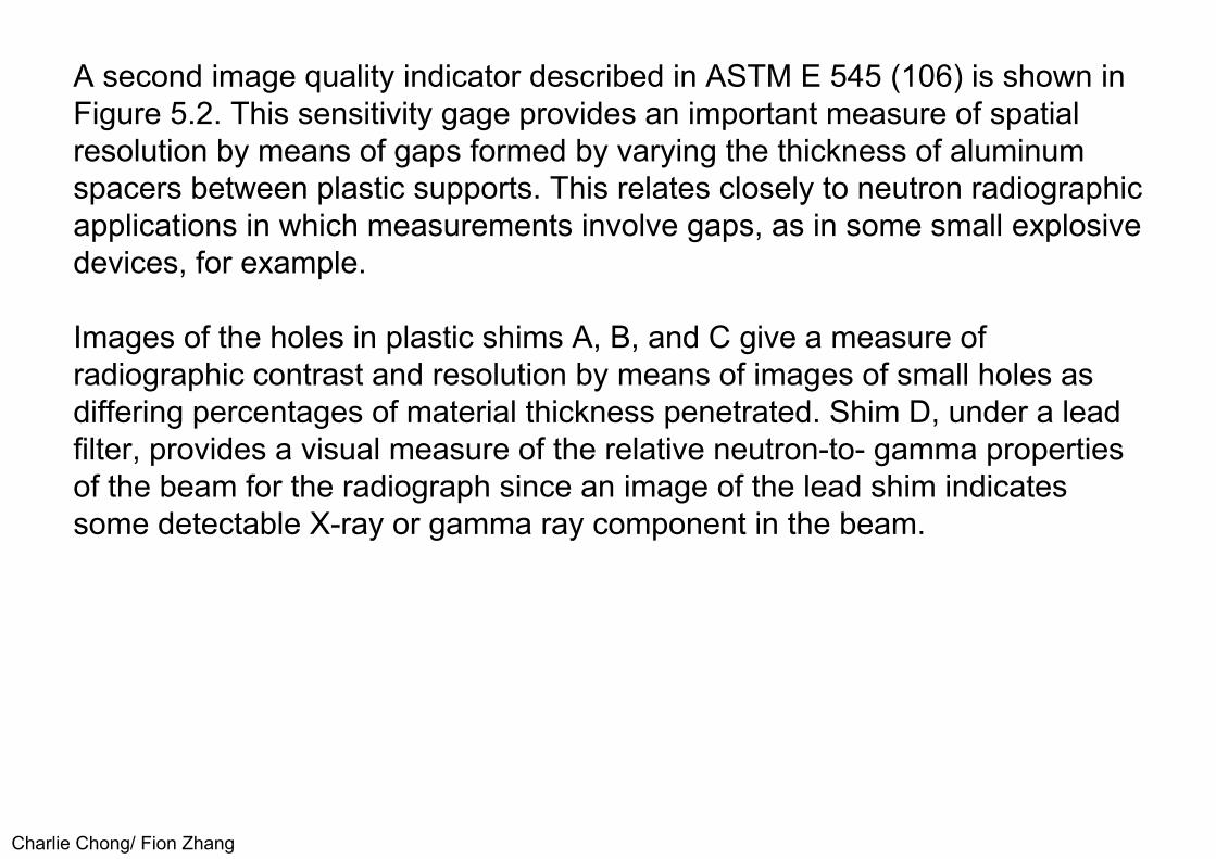
Charlie Chong/ Fion Zhang
A second image quality indicator described in ASTM E 545 (106) is shown in Figure 5.2. This sensitivity gage provides an important measure of spatialresolution by means of gaps formed by varying the thickness of aluminumspacers between plastic supports. This relates closely to neutron radiographicapplications in which measurements involve gaps, as in some small explosivedevices, for example.
Images of the holes in plastic shims A, B, and C give a measure of radiographic contrast and resolution by means of images of small holes as differing percentages of material thickness penetrated. Shim D, under a lead filter, provides a visual measure of the relative neutron-to- gamma properties of the beam for the radiograph since an image of the lead shim indicates some detectable X-ray or gamma ray component in the beam.

Charlie Chong/ Fion Zhang
Figure 5.2. Sensitivity Gage as described in ASTM E 545, 1991. (From ASTM E 545, reference 106.) Reprinted with permission.

Charlie Chong/ Fion Zhang
Sensitivity Indicator

Charlie Chong/ Fion Zhang

Charlie Chong/ Fion Zhang
All measurements relating to ASTM E 545 (106) were developed for directexposure neutron radiographs with single emulsion film and a singlegadolinium conversion screen. It is recognized in the standard thatmeasurements for other neutron radiographic detection systems may notrelate well. There are efforts in ASTM to rewrite E 545 in order to produce onedocument that describes how to perform the measurements (as presently in E545) and another document to describe how to fabricate the image qualityindicators. These changes, should they take place, are not expected to resultin any significant changes in the present concept of the standard.
Keywords:ASTM E545Direct exposureSingle emulsion filmSingle gadolinium conversion screen
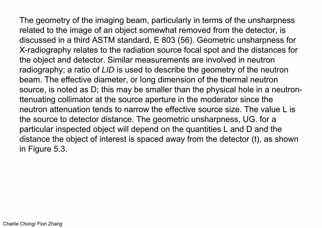
Charlie Chong/ Fion Zhang
The geometry of the imaging beam, particularly in terms of the unsharpness related to the image of an object somewhat removed from the detector, isdiscussed in a third ASTM standard, E 803 (56). Geometric unsharpness forX-radiography relates to the radiation source focal spot and the distances forthe object and detector. Similar measurements are involved in neutronradiography; a ratio of LID is used to describe the geometry of the neutronbeam. The effective diameter, or long dimension of the thermal neutronsource, is noted as D; this may be smaller than the physical hole in a neutron-ttenuating collimator at the source aperture in the moderator since theneutron attenuation tends to narrow the effective source size. The value L isthe source to detector distance. The geometric unsharpness, UG. for aparticular inspected object will depend on the quantities L and D and thedistance the object of interest is spaced away from the detector (t), as shownin Figure 5.3.

Charlie Chong/ Fion Zhang
The distances L and D are indicated on the figure. The geometricunsharpness (U0 ) of an object spaced a distance t from the detection plane is calculated as follows:
Ug = Dt/(L-t) (Eqn. 5.1)
For the common situation in which t is small compared to L, Equation 5.1 reduces to the following approximation:
Ug = t∙D/L (Eqn. 5.2)
The measurement of L/D as described in ASTM E 803 (56) involves a test piece with absorbing materials (rods) spaced at various distances (t) from the detection plane. A diagram of the test piece is shown in Figure 5.4. The image of this test piece can be used for a visual measure of unsharpness(and thereby L/D) by observing where the absorbing rod images degrade. The test piece also lends itself to scanning microdensitometer measurements for more quantitative values.

Charlie Chong/ Fion Zhang
Figure 5.3. Geometry of a neutron radiographic system.
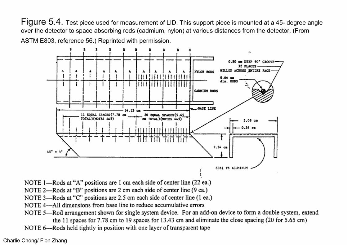
Charlie Chong/ Fion Zhang
Figure 5.4. Test piece used for measurement of LID. This support piece is mounted at a 45- degree angle over the detector to space absorbing rods (cadmium, nylon) at various distances from the detector. (From ASTM E803, reference 56.) Reprinted with permission.
Charlie Chong/ Fion Zhang
The standard describing methods for obtaining object dimensionalmeasurements from neutron radiographs (105) outlines a procedure forexamining the film density change at the edge of an object, making use of ascanning microdensitometer. Analysis of the film density vs. Distance edgetrace can be used to establish the object edge location to repeatability valuesof 25 microns and reproducibility values of 100 microns or less. These valuesare predicated on stringent conditions for the neutron radiographic beam, theimaging geometry and the measurement system.
These ASTM standards provide a recognized (and standardized) approach to measurements related to neutron radiography. Other documents are also available. Glossaries of neutron radiographic terms have been published by ASTM (26) and also in a military standard (MIL-STD-1948, Ref. 27). Reference 27 includes definitions for more than 150 terms. A book of reference neutron radiographs, specifically related to the inspection of nuclear fuel has proven to be a valuable reference book for the nuclear community (17).

Charlie Chong/ Fion Zhang
There is also an excellent collection of neutron radiographs prepared by the Japanese Society for Non-Destructive Inspection (20). Two standards for neutron radiography have been developed in France (107, 108) for the characterization of facilities and the determination of film speed and contrast. A discussion of these and other aspects of neutron radiographic standards is given in a review by Berger and LaPorte (109). Other reviews of neutron radiographic standards are given by Haskins (110, 111) and Brenizer (112).
Charlie Chong/ Fion Zhang
5.2 PERSONNEL QUALIFICATIONNeutron radiography, like other nondestructive testing procedures, requires trained, qualified people to do the testing. Training and certification of neutronradiographic operators is described in a military standard (MIL-STD-410E,Ref. 3) and in documents available from theAmerican Society forNondestructive Testing (1 and 2). Both documents outline the training andpractical experience needed to qualify for various levels of responsibility.
The basic subjects required for neutron radiographic operator training areout1ined briefly in Table 5.1; Additional information is available in thereferences cited (113, 114, 115). Obviously a neutron radiographic operatorwho is already qualified in X-radiography (radiographic testing) will berelatively easier to train for neutron radiographic testing since the operator willalready have basic knowledge of radiation, sources, detectors, imaginggeometry, scatter, film processing and interpretation. Once the new neutronradiographer learns how neutrons are generated, attenuated and detected,the basic knowledge for performing neutron radiography will be available foruse.

Charlie Chong/ Fion Zhang
Table 5.1 General Training Topics for Neutron Radiographic Training

Charlie Chong/ Fion Zhang
5.3 REGULATORY CONTROLIn the United States, radiation equipment is controlled by the government as a safety measure. Primary control is at the federal level with the U.S. NuclearRegulatory Commission; this control is primarily concerned with radioactivesources and nuclear materials as described in the Atomic Energy Act of 1954and the federal regulations (106). For neutron radiography, this federal controlclearly involves radioactive neutron sources such as 252Cf or 241Am-Be, etc.Sources that include nuclear fuel material for use as a sub-critical assemblyare also covered by the federal regulations (51, 52), as are reactor sources.
States also have radiation control requirements. In many cases the states,known as Agreement States, have taken over parts of the regulatory controlfrom the federal government. In addition, many states and local governmentsmaintain control over all radiation sources, including the machine oraccelerator sources not generally covered by federal regulations.
A description of the government regulatory program is given in Reference 50.The major objective of the government control is to assure safe use ofradiation to protect the radiation worker and the general public.

Charlie Chong/ Fion Zhang
6.0 APPLICATIONS6.1 GENERAL APPLICATIONSAs indicated previously in Section 1, differences in attenuation between neutrons and X-rays (or gamma rays) lead to applications for eachradiographic method. In general terms, thermal neutron radiography tends tocomplement X-radiography in that, for neutrons, there is strong attenuation forseveral low atomic number (Z) materials and high transmission for many highZ materials; for X-rays the situation is reversed. Observation of hydrogenousmaterial such as a rubber "0" ring in a steel assembly can be considered forthermal neutron radiography whereas such an application would be difficultfor X-radiography. In the neutron case, the attenuation of the hydrogenousrubber ring would be significant. In the X-ray case, once the X-ray energy israised to penetrate the steel case, the X-ray attenuation in the rubber or otherlow Z material would be very low.
Charlie Chong/ Fion Zhang
Clearly, considering cost and availability of equipment, X-ray or gamma raytechniques should be used where these methods will solve the problem. Forsituations where X-ray methods do not provide sufficient information, neutronradiography should be considered.
Generally, inspection of a homogeneous material such as a steel casting, is best done by X-rays or some other NDT technique.
Neutron radiography normally offers advantages for inspections of multi-material components or assemblies where it is desired to observe onematerial in the presence of another.
Charlie Chong/ Fion Zhang
There are four general classes of application problems where neutron radiography offers advantages (1-20), as follows:
1. Detection of high neutron attenuating material in a matrix of a relativelytransmitting material. Advantage may be taken of the differences betweenthermal neutron and X-ray attenuation as shown earlier in Figure 1.1.Contrast agents such as liquid penetrants and as described in Section 4.6may offer advantages in certain crack detection applications. An example oflow Z type of application is shown in Figure 6.1, a neutron radiograph of aportion of an assembly, showing "0" rings inside a metal case; twisted "0“ rings, that would not seal properly, are easily seen in the neutron image.Figure 4.1 showed another example, imaging of hydrogen-containing materialin a steel matrix.

Charlie Chong/ Fion Zhang
Figure 6.1. Thermal neutron radiograph of a metal assembly showing "0“ rings. The arrows indicate rings that have twisted out of the groove so thatthey no longer seal (122). Courtesy Aerotest Operations Inc.

Charlie Chong/ Fion Zhang
2. Inspection of radioactive material (taking advantage of the capability to detect neutrons without sensitivity to gamma rays, as in the transfer or track- tch detection methods). Examples of such neutron radiographs were shown in Figures 4.2, 4.3 and 4.5.
3. Detection of differences in isotopic content. Neutrons offer sensitivity to different isotopes of the same element. For example, U-238 is relatively transparent while U-235 is highly attenuating for slow neutrons. An example of a neutron radiograph of nuclear fuel showing differences in attenuation for different fuel isotopes is shown in Figure 4.5.
4. Inspection of relatively thick, neutron-transparent material because ofdecreased exposure time (as compared to X-ray techniques). An examplewould be inspection of lead shielding to detect voids.

Charlie Chong/ Fion Zhang
These general classes of applications are discussed in the following sections.
Additional general information on applications may be found in many of the earlier references cited; see in particular references 1 to 20.
Table 6.1 shows typical half-value layers for thermal neutrons. Additional half-value layer information can be gained by looking at neutron cross sectionvalues (37, 41); material is also available in Ref. 55. The values listed belowwill suggest other applications for neutron radiography.

Charlie Chong/ Fion Zhang

Charlie Chong/ Fion Zhang
6.2 AEROSPACE APPLICATIONSThe aerospace industry is a major user of neutron radiography. Applications include inspections to detect corrosion, residual core in investment castturbine blades and residuals in other applications such as cooled rocketnozzles, inspections of explosive lines and other small explosive devices,adhesive bonds, composites and assemblies of many types to assure properplacement of components such as rubber "0" rings (see Figure 6.1 ).Detection of corrosion in aircraft structures is an active application area forneutron radiography. Since corrosion products are typically hydroxides, thebuild-up of the corrosion product can often be detected by thermal neutronradiography before there is appreciable loss of metal; Other nondestructivetest methods for corrosion detection depend primarily on observation of metalloss (28, 29, 30, 44, 47, 117, 118). Examples of neutron radiographs showingimages correlated with corrosion are shown in Figures 6.2 and 6.3. Figure 6.2is a film neutron radiograph of an aluminum aircraft honeycomb structure,showing spots of corrosion after insertion of water (119). Figure 6.3 is aneutron radioscopic image showing dark areas of corrosion in an aluminumaircraft structure, taken with a reactor source and a neutron image intensifierdetection system (120).
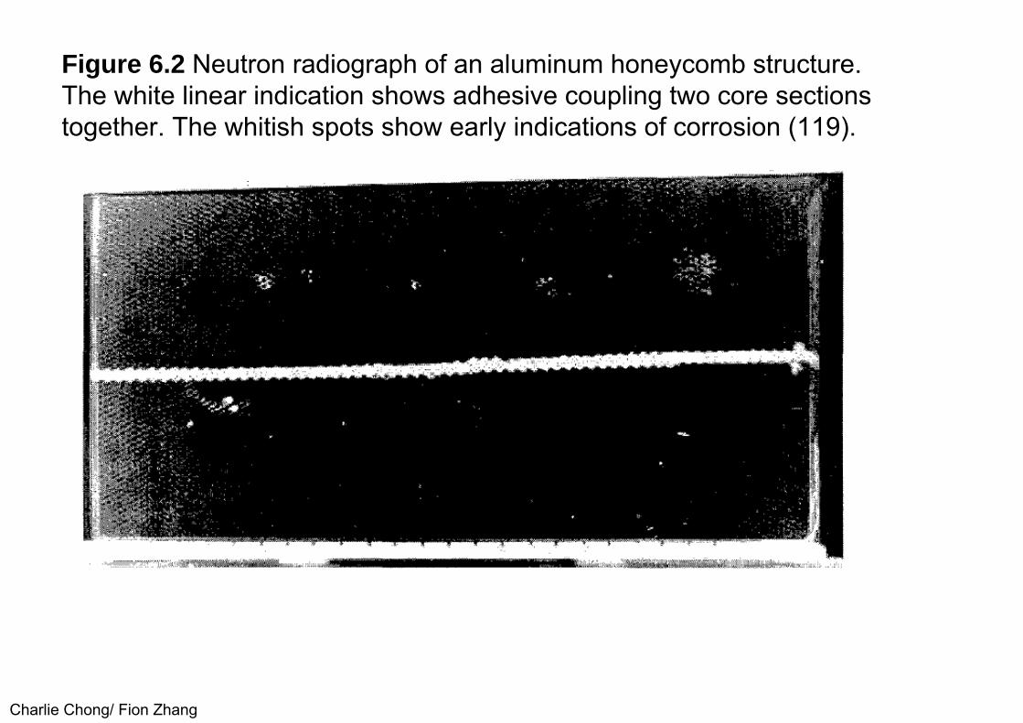
Charlie Chong/ Fion Zhang
Figure 6.2 Neutron radiograph of an aluminum honeycomb structure.The white linear indication shows adhesive coupling two core sectionstogether. The whitish spots show early indications of corrosion (119).
Charlie Chong/ Fion Zhang
Figure 6.3 Neutron radioscopic image of an aluminum aircraft structureshowing images of corrosion (dark, irregular areas, particularly in the upperleft). The rectangular image at lower left shows an acrylic, stepped wedge testpiece containing holes (120).

Charlie Chong/ Fion Zhang
Reports describing experiments with polyethylene to simulate the hydrogencontent of typical corrosion products in aluminum indicate that thermalneutron radiography will detect corrosion product build-up equivalent to 0.001inch metal loss in aluminum (118, 120). Recent work on the use of neutronradiography to detect corrosion has led to the design and operation of apractical inspection facility for aircraft maintenance (29, 119, 121) atMcClellan Air Force Base in California. The facility includes a reactor sourcefor neutron radiography of components removed from the aircraft and arobotic system for neutron radiography of components on the aircraft. Aportion of the robotic arm and Cf-252 source assembly for this operationalmaneuverable neutron radiography system is shown in the photograph inFigure 6.4; the inset is an artist's design view of the maneuverable inspectionsystem (119). Many transportable neutron radiographic systems have alsobeen developed. Examples were shown in Figures 3.3, 3.5 and 3.6 (30, 44,45, 46, 47, 63).

Charlie Chong/ Fion Zhang
Investment-cast turbine blades are made by molding metal around a ceramic core and then leaching away the ceramic to leave open internal coolingpassages. Since neutrons are sensitive to many of the rare earth materialsfound in ceramics, small amounts of residual core material can be detected.Sensitivity is often further enhanced by adding a few percent of gadolinia tothe ceramic core material (or using a gadolinia solution wash before theneutron radiographic inspection). The addition of the high neutron crosssection gadolinium material as a contrast agent permits detection of very thinresidual ceramic films that might impede the thermal transfer characteristicsof a turbine blade and lead to failure (103, 104, 122). Similar neutronradiographic applications have been demonstrated to detect wax cores incooled rocket nozzles (122). An example of a turbine blade neutronradiograph was shown in Figure 4.7.

Charlie Chong/ Fion Zhang
Ceramic materials can also sometimes be usefully inspected by neutron radiography (122). Other applications involve inspection of assemblies to detect rubber or plastic seals, detection of adhesives in bonded assemblies and inspection of explosive devices (104, 122). All these types of neutron radiographic inspections have been very valuable. The rubber or other neutron absorbing gasket material can be readily detected, even in a metallic assembly. Hydrogenous adhesives can be imaged in metallic assemblies to assure the presence of the adhesive, and sometimes the degree of the adhesive cure by observation of the bubble structure. Composite materials can be inspected to detect variations in density, resin content and excess moisture. Explosive inspection is a major application area in itself, to be covered in the following section. A typical aerospace application is the inspection of lead or stainless steel encased explosive lines of the type used to separate components and eject military pilots in emergency situations.

Charlie Chong/ Fion Zhang
Figure 6.4 Photograph of a robotic arm at the maneuverable inspection bay at McClellan Air Force base. The large round structure at lower left is themoderator-collimator housing for the Cf-252 neutron source. The inset is a diagram of the on-aircraft inspection facility for F-111 aircraft (29, 119).

Charlie C
hong/ Fion Zhang
Charlie Chong/ Fion Zhang
6.3 EXPLOSIVE DEVICESExplosive materials typically contain neutron attenuating material such as hydrogen, lithium, or boron. Therefore, explosive materials usually shadowwell on a neutron radiograph, even when encased in an assembly with metal.A typical range of thermal neutron half-value layers for explosives was givenin Table 6.1. Explosive lines and bolts, detonators, and similar smallexplosive devices are readily inspected by neutron radiography. Thepurposes for the inspection may include one or more of the following:
1. Assurance that the explosive is present, in the correct location, and in thecorrect amount.
2. Measurement of gaps (often necessary).3. Detection of voids, density variations, cracks, or contamination.
Neutron radiographs of explosive devices were routinely taken for many years with a Cf-252 subcritical assembly source (51, 52). Inspection of small explosive devices is also a common application at a neutron radiography service facility reactor source (104, 122). Since many of the explosive devices to be inspected are relatively small, an assembly of many devices on oneradiograph is typical.

Charlie Chong/ Fion Zhang
Examples of neutron radiographs of small explosive devices are shown in Figures 6.5, 6.6, 6.7 and 6.8. Figures 6.5 and 6.6 show explosive bolt images.Figure 6.7 shows a comparison of radiographs of 45-caliber ammunition,taken with thermal neutrons and x-rays (122). Figure 6.8 illustrates neutronimages of explosive tips. Neutron radiographs of larger explosive devices issometimes done even though the attenuation of thermal neutrons makes itdifficult to penetrate larger devices. Such a thermal neutron radiograph isshown in Figure 6.9; the radiograph of an ordnance device 2% inch diametershows detail mainly in the upper, thinner areas and in the region of theinternal cracks in the central unit (123); the radiograph shows usefulinformation that can supplement that obtained from a conventional X-rayimage.

Charlie Chong/ Fion Zhang
Figure 6.5 Neutron (left) and X-radiographs (right) of an explosive bolt about 2 inches high. The x-ray image shows the metallic parts. The neutron imageshows plastic, epoxy, paper (slanted white line near the top) and theexplosive charge (salt and pepper image near the top, inside the stainlesssteel cap) (34).

Charlie Chong/ Fion Zhang
Figure 6.6 Neutron (left) and x-radiographs (right) of three explosive bolts (A,Band C) showing differences in the images (122). Courtesy: AerotestOperations, Inc.
Charlie Chong/ Fion Zhang
Figure 6.7 Neutron radiographs of 45-caliber ammunition (upper views)compared to x-ray images at 150 kV (lower left) and 90 kV (lower right)(122). Courtesy: Aerotest Operations, Inc.

Charlie Chong/ Fion Zhang
Figure 6.8 Neutron radiographs ofsmall explosive tips used to initiate mechanical actions in remote locations. The tip at left is satisfactory although the upper pellet shows slightly lower density. The tip at right shows separation between the two pellets. Themiddle sample (tip at the bottom)shows a missing pellet.
Charlie Chong/ Fion Zhang
Figure 6.9 Neutron radiograph of an ordnance device, 2% inchdiameter, showing detail near thethin top and in the cracked regionat lower center. Courtesy: J.Moravec, U.S. Army ProvingGround, Yuma. Arizona.

Charlie Chong/ Fion Zhang
6.4 ELECTRONIC DEVICESThe inspection of critical epoxy-potted, small electronic devices such as filters can be accomplished effectively by neutron radiography. The relatively highattenuation of the potting materials (usually hydrogenous) means that smalldiscontinuities can be detected with neutrons, even though the assembly is ina metallic case. In addition, neutron inspection of critical relays can discloseproblems with hydrogenous material, such as loose insulation, inside therelay case that could cause connection problems at an important moment.Neutron images of relays are shown in the neutron radiograph in Figure 6.10(122).
Delaminations in high reliability ceramic capacitors have been successfully detected using neutron radiography, another example of neutron radiographicelectronic applications (124). Because there are many effectivenondestructive testing methods used for electronic devices - radiography,infrared, acoustic emission, etc. - neutron radiography is not broadly applied.However, for the types of applications indicated here, neutron radiographyhas contributed to improved reliability in critical electronic components.

Charlie Chong/ Fion Zhang
Figure 6.10 Neutron radiographs of relays. Any foreign materials could resultin electrical connection problems (119). Courtesy Aerotest Operations, Inc.
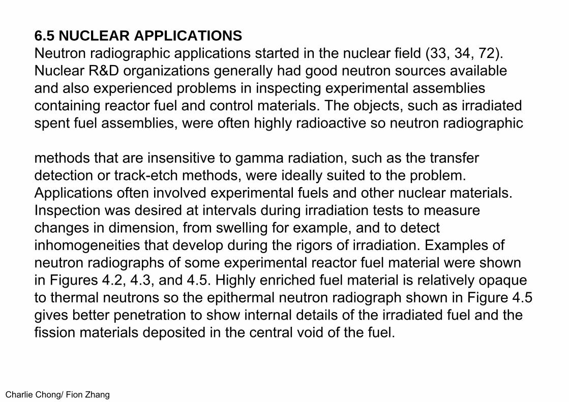
Charlie Chong/ Fion Zhang
6.5 NUCLEAR APPLICATIONSNeutron radiographic applications started in the nuclear field (33, 34, 72). Nuclear R&D organizations generally had good neutron sources availableand also experienced problems in inspecting experimental assembliescontaining reactor fuel and control materials. The objects, such as irradiatedspent fuel assemblies, were often highly radioactive so neutron radiographic
methods that are insensitive to gamma radiation, such as the transfer detection or track-etch methods, were ideally suited to the problem.Applications often involved experimental fuels and other nuclear materials.Inspection was desired at intervals during irradiation tests to measurechanges in dimension, from swelling for example, and to detectinhomogeneities that develop during the rigors of irradiation. Examples ofneutron radiographs of some experimental reactor fuel material were shownin Figures 4.2, 4.3, and 4.5. Highly enriched fuel material is relatively opaqueto thermal neutrons so the epithermal neutron radiograph shown in Figure 4.5gives better penetration to show internal details of the irradiated fuel and thefission materials deposited in the central void of the fuel.

Charlie Chong/ Fion Zhang
Nuclear applications have included examinations of nuclear fuel, both before and after irradiation. Pre-irradiation radiographs are useful for comparisonafter irradiation; they have also disclosed contaminating material such asplastic sheet in~dvertently left inside assemblies. Entry into a fuel assembly offoreign material such as water and hydriding of metallic components has alsobeen observed using neutron radiography (125). Nuclear attenuating controlmaterials have been inspected with neutron radiography as have othernuclear components such as cold traps (126). Radioactive sources can alsobe inspected to detect voids or other problems. A significant capability ofneutron radiography is represented by the possibility to differentiate betweenparticular isotopes, as indicated earlier. This has been used to some degreein the nuclear field to differentiate between isotopes of fuel materials beforeand after irradiation and to determine bum-up in control materials. Nuclearapplications of neutron radiography continue at nuclear centers around theworld.

Charlie Chong/ Fion Zhang
Recent work has included techniques such as tomography (84). This technique for imaging cross sections of assemblies has been particularlyuseful for imaging details in fuel subassemblies. These subassemblies maycontain 60 or more individual fuel pins in an array. Since it is desired toinspect each pin, the subassembly must be taken apart or a technique suchas tomography or laminography (127) can be used. In tomography, theradiation attenuation along many paths through the object is determined. Thisinformation is used to reconstruct the cross-sectional image of the object. Fortomography of nuclear fuel, many radiographs taken at different angularorientations can be digitized to obtain the initial data. As few as 75 views canbe used to obtain the initial data (84) for reconstruction.

Charlie Chong/ Fion Zhang
6.6 MOTION/DYNAMIC APPLICATIONSNeutron time lapse radiographs and dynamic detectors such as neutron image intensifiers and scintillator-camera systems have been used to obtaininformation about dynamic events. Demonstrations of capability have beenmade to observe thermal expansion of nuclear fuel material and to follow liquid metal in the casting process (see Figure 4.4). Application studies in ballistics have required very fast image frame rates to obtain useful data from rapid motion. This has been accomplished with a pulsed reactor and high speed cameras. Images have been observed at rates as high as 10,000 frames/second (77). A number of neutron applications for dynamic events have been pursued with conventional television frame rates (30 frames/ second) using television cameras and new solid state cameras to detect the light from neutron scintillators or neutron image intensifier tubes.

Charlie Chong/ Fion Zhang
Applications have included observations of fluid flow in metallic assemblies, for example, jnvestigations of heat pipes to optimize the fluid flow and the heat transfer of the system (128). Extensive motion studies of lubricants and fuels have been conducted in engines and engine components to learn more about the dynamics (76, 78, 79, 80, 81, 130, 131). Some of this work has been done with lower energy, cold neutrons (78) in order to provide greater sensitivity to the hydrogenous fluid, and greater penetration through the surrounding metal. An example of results from an engine study is given in Figure 6.11. The two neutron radioscopic images show a GEM turboshaftengine, one a static view (left) and the other a dynamic view (right). The oil scavenge pipe (slightly bent pipe at lower center of the images) is shown full of oil in the static view but with very little oil in the dynamic view. The neutron radioscopic tests led to a redesign of the engine to permit oil to flow freely during engine operation (78).
Dynamic neutron imaging studies have also been used for a variety of other applications, including real-time inspection applications to detect aircraftcorrosion, hydrogen locations in titanium, and to study pneumatic systems,filters and moisture/water migration (29, 44, 47, 82, 85, 87).

Charlie Chong/ Fion Zhang
Figure 6.11. Neutron radioscopic images of a GEM turboshaft engine. Left isa static view. Right is a dynamic view, engine running. The images show thatthe oil scavenge pipe (lower center) has little oil in it during operation, anindication of poor oil circulation (78).

Charlie Chong/ Fion Zhang
6. 7 MISCELLANEOUS APPLICATIONSThere are many neutron inspection applications that have not been specifically cited. Many such applications are discussed in References 1 to 20.There have been medical/biological investigations for neutron radiography.For in-vivo ( applications, the results have been relatively negative (132); Theextensive neutron attenuation of tissue presents problems in penetration anddose. Biological work on excised samples, however, has produced usefulresults. Neutron radiography has been shown to be useful for detecting andconfirming the extent of tumors in bones removed from patients (133). Newneutron radiographic results to show application of neutron radiography todetect lung cancer in mice have shown promise, mainly as a result ofextensive image processing (134). Diffusion studies have been successfullydone to observe the movement of water/moisture in concrete samples as afunction of time/temperature, as well as water movement in plants (135, 136).Movement of smoke, aerosols and contrast media through filters has beeninvestigated (137, 138, 139). Soils have been investigated to complement X-adiographic results (140, 141).
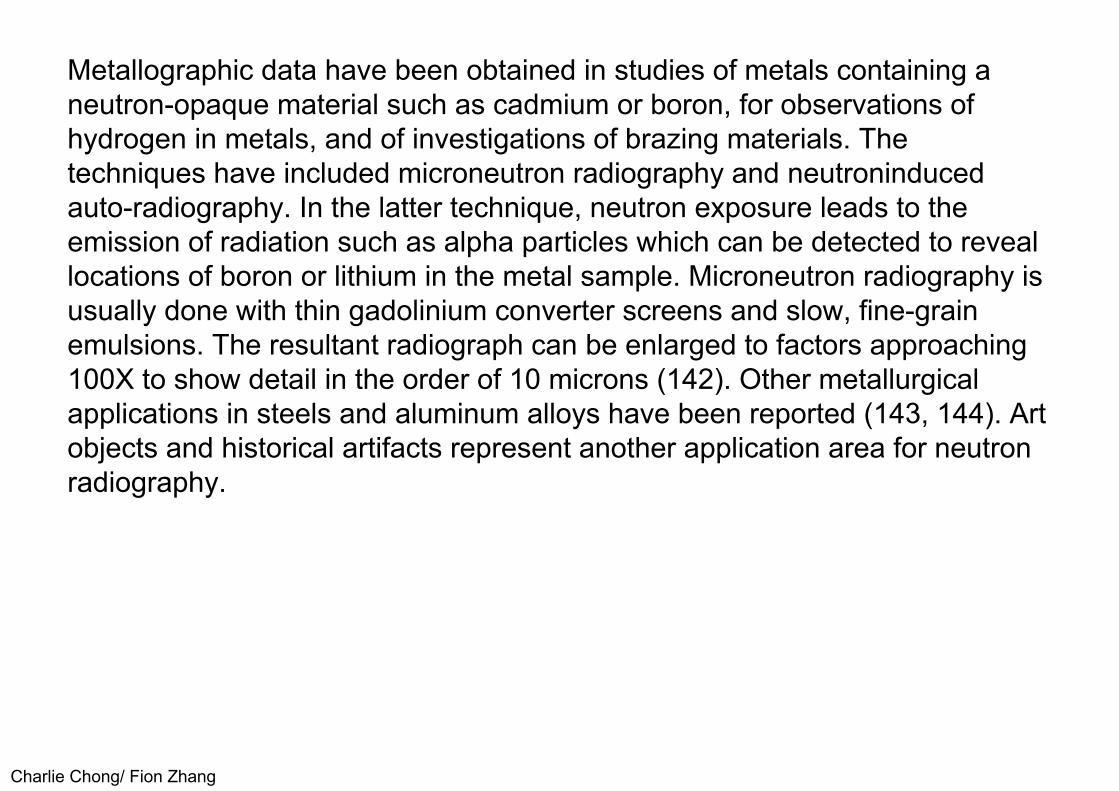
Charlie Chong/ Fion Zhang
Metallographic data have been obtained in studies of metals containing a neutron-opaque material such as cadmium or boron, for observations ofhydrogen in metals, and of investigations of brazing materials. Thetechniques have included microneutron radiography and neutroninducedauto-radiography. In the latter technique, neutron exposure leads to theemission of radiation such as alpha particles which can be detected to reveallocations of boron or lithium in the metal sample. Microneutron radiography isusually done with thin gadolinium converter screens and slow, fine-grainemulsions. The resultant radiograph can be enlarged to factors approaching100X to show detail in the order of 10 microns (142). Other metallurgicalapplications in steels and aluminum alloys have been reported (143, 144). Artobjects and historical artifacts represent another application area for neutronradiography.

Charlie Chong/ Fion Zhang
The complementary nature of neutron radiography often reveals details that cannot readily be detected by other methods (145, 146, 147). An example of a neutron radiograph of a rare historical object is shown in Figure 6.12 (146). The object was a lead vessel about 25 em in height, dating from the Western Chou period in China, approximately 1000 B.C. Neutrons easily penetrated the lead walls of the vessel to show evidence of early repairs and to confirm that the vessel was empty. X-ray tests were inconclusive because of the significant attenuation of the lead walls. This neutron radiograph was taken by a xeroradiographic method using a gadolinium oxysulfide conversion screen. The xeroradiographic detection method used for this application serves to illustrate that any method that can be used for X-ray inspection can be considered for neutron radiography.
Charlie Chong/ Fion Zhang
A related neutron technique in the art world involves neutron autoradiography of paintings. Neutron exposure excites radioactive emissions from the paintpigments. These can be studied as a function of time after the neutronradiation is complete to produce images from different paint materials. Themethod is used to bring out underlying paintings, to verify authenticity, and tostudy artist's technique (147, 148).
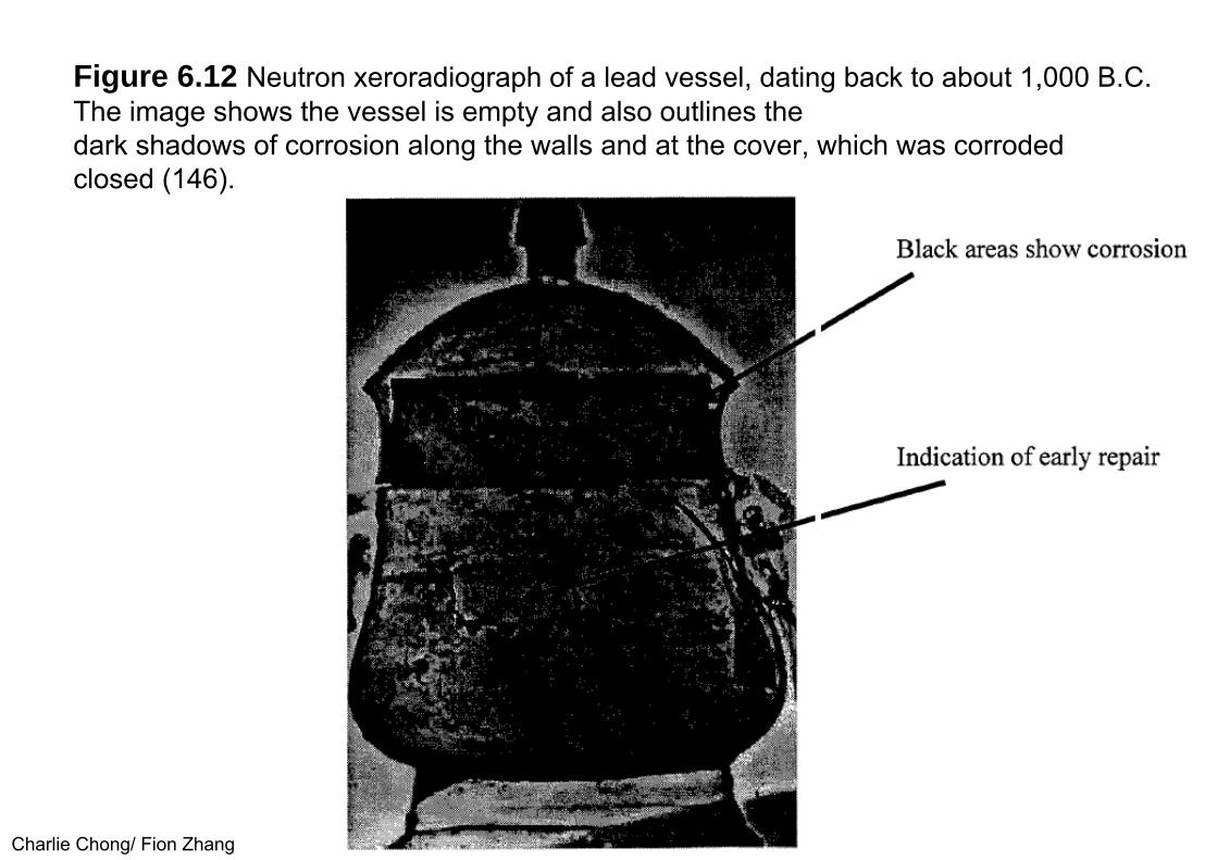
Charlie Chong/ Fion Zhang
Figure 6.12 Neutron xeroradiograph of a lead vessel, dating back to about 1,000 B.C. The image shows the vessel is empty and also outlines thedark shadows of corrosion along the walls and at the cover, which was corroded closed (146).
Charlie Chong/ Fion Zhang
7.0 CONCLUSIONSNeutron radiography continues to offer inspection solutions for many difficult problems, as has been discussed throughout this review of the technology.Significant advances have been realized in recent years in terms of neutronsources and electronic imaging techniques. Sources now available include arange of accelerators that can be considered for either fixed installation ortransportable systems. Cold neutron sources, including guide tube techniquesthat bring a gamma-free neutron beam to a position remote from the reactorsource, are now more readily available for neutron research and radiographyand the special problems that can be solved by the use of these very lowenergy neutrons (151 ). Electronic image systems for slow and fast neutronshave been described, offering large fields-of-view and prospects for improvedsensitivity and spatial resolution (73). The combination of high outputaccelerator sources and electronic image detection is leading to considerationof practical aircraft inspection systems that offer good economic potential forearly detection of corrosion.
Charlie Chong/ Fion Zhang
Standards for neutron radiography continue to advance and mature as experience is gained with the existing standards. Active standards workcontinues in ASTM, through Committee E-7 on Nondestructive Testing andinternationally through ISO, the International Organization for Standardization;the group directly involved internationally is ISO/TC 135/SC 51 WG 4, underthe auspices of !SO-Technical Committee 135, Nondestructive Testing,Radiation Subcommittee 5 and the Neutron Radiography Working Group 4.Current contact (1998) for the neutron radiography standards work in bothASTM and ISO is Dr. Jack Brenizer, University of Virginia. Brenizer is theChairman of ASTM Subcommittee E 7.05 and the Convenor of the ISOWorking Group. Contact with Brenizer may now be made at the PennsylvaniaState University in University Park, PA.
Charlie Chong/ Fion Zhang
As implied in the description of the standards work, there is strong neutron radiography activity in the international community. In Europe, an active groupis the Eurapean Neutron Radiography Working Group (ENRWG), whichincludes representatives from many of the European centers. A currentcontact for the ENRWG is Dr. Marton Balask6, KFKI Atomic Energy ResearchInstitute in Budapest, Hungary. In Japan, where many neutron radiographyresearch and application programs are under way, there is an active neutronradiography group organized under the auspices of the Japan Atomic EnergyResearch Institute (JAERI), Tokai Establishment; a contact is Dr. ShigenoriFujine at the Research Reactor Institute at Kyoto University in Osaka. A newtechnical society has been formed to address issues relative to neutronradiography, the International Society for Neutron Radiology (8); the currentPresident is Dr. Keiji Kanda, Research Reactor Institute, Kyoto University inOsaka. Complete addresses for the people named in this international activityparagraph can be found in recent international conference proceedings (8, 10,11 ).

Charlie Chong/ Fion Zhang
Neutron radiographic service work is available from at least two organizations in the United States. Aerotest Operations, Inc., San Ramon, CA and GeneralElectric, Nuclear Test Reactor, Vallecitos, CA are known to providecommercial neutron radiographic service, including the capability to inspectexplosive devices. In Canada commercial neutron radiographic service isavailable from NRA Y Services, Inc., Petawawa, Ontario. In addition, severalforeign centers offer such services; contacts may be made through the ENRWG or JAERI. Limited neutron radiographic services are also made availableoccasionally through university neutron radiographic centers on a case-by-ase basis. Contacts for such services may be found in current conferenceproceedings (8, 10, 11). The future for neutron radiography appearspromising, both in terms of research and applications. Research activitycontinues at a high level, as indicated in the number of papers and attendeesat neutron radiographic meetings. A growing number of practical applicationshas been demonstrated at these periodic conferences. In addition, theextensive neutron radiographic facilities for aircraft inspection at the Air ForceAir Logistics Center, McClellan Air Force Base in Sacramento, CA are comingto the attention of the air<traft community.
Charlie Chong/ Fion Zhang
In 1998 the Federal Aviation Administration issued an Air Agency Certificatcl for that facility for a broad range of nondestructive inspection techniques, including neutron radiography, for inspection of selected commercial aircraft (152). The likely impact of this event will be the introduction of several more aircraft inspection facilities around the world, each offering neutron radiographic inspection for early detection of corrosion.
Looking toward the future, there are many opportunities for advanced techniques and applications in the field of neutron radiography. Since imagedetection methods used for x-rays have been relatively easily transferred forneutron imaging use, one can envision that new, emerging, electronic x-rayimage methods will be adapted for neutron use (154). Initial work has alreadybeen reported on the use of photostimulable phosphor plates for neutronradiographic use (94, 95, 96). These storage phosphor detectors are re- sable,thereby eliminating the continuing cost of film and easing environmentalproblems in the use and disposal of film processing chemicals. In addition,the storage phosphor technique offers wide dynamic range, digital imaging.
Charlie Chong/ Fion Zhang
Another rapidly maturing x-ray imaging technology is the flat panel, a large area, solid state detector, such as amorphous silicon, made up ofcombinations of photodiodes and an integral thin film transistor (154, 155).These image panels also offer the wide dynamic range, digital imagingadvantages indicated above for the storage phosphor, plus the capability fordynamic response. The panels are showing advantages for medicaldiagnostic x-ray imaging, as well as industrial applications over a broad rangeof x-ray energies, from less than 100 ke V to the MeV range. There areadvances in non-reactor neutron sources, as described in Section 3.4.
Developments include high neutron yield linear accelerators, cyclotrons andlow voltage ( d, T) sources (28). Fast neutron yields from these sources are inthe order of 1011 to 1012 n/s, outputs that give these sources neutronradiographic image quality approaching those from reactor beams. In addition,portability is being investigated more vigorously, as shown in Figures 3.3, 3.5and 3.6. The combination of high yield, transportable neutron sources andelectronic neutron imaging offers promise for increased application of thisinspection technique.

Charlie Chong/ Fion Zhang
Neutron energy ranges outside of cold neutrons, the widely used thermal energy range and the sometimes used near-epithermal neutron energy range(see Figure 4.5), also offer promise for further development andapplication. Resonance energy neutrons, as described in Table 1.1, can showexceptional sensitivity for particular materials such as indium or gold,materials that show resonance response in the near epithermal energy range(12). A real application for resonance neutron radiography would advance thefield. Epithermal neutrons in the 1,000 or more ev range offer reasonableprospects for materials discrimination contrast approaching that of thermalneutrons, while also providing much improved neutron transmission throughthick objects. An inspection such as the ordnance devices shown in Figure6.9, for example might benefit from the use of high epithermal neutrons.Opportunities for future advances in neutron radiography are likely asresearch and development work continues to more fully explore neutronenergies, sources and detectors and the opportunities these developmentsmay offer.

Charlie Chong/ Fion Zhang
Peach – 我爱桃子

Charlie Chong/ Fion Zhang
Good Luck

Charlie Chong/ Fion Zhang
Good Luck

Charlie Chong/ Fion Zhanghttps://www.yumpu.com/en/browse/user/charliechong