unit – 3 electrostatics - karnataka examination ... – 3 electrostatics question paper blue print...
TRANSCRIPT
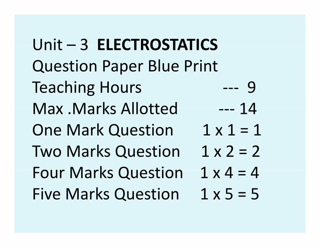
Unit – 3 ELECTROSTATICSUnit – 3 ELECTROSTATICSQuestion Paper Blue PrintTeaching Hours ‐‐‐ 9Max Marks Allotted 14Max .Marks Allotted ‐‐‐ 14One Mark Question 1 x 1 = 1Two Marks Question 1 x 2 = 2Four Marks Question 1 x 4 4Four Marks Question 1 x 4 = 4Five Marks Question 1 x 5 = 5
Electric charge:• Electric charge:It is a fundamental It is a fundamental property of matter property of matter which is responsible for pelectrical effects.
•Charge is a scalar•Charge is a scalar quantity Its S I unitquantity. Its S I unit
is coulomb (C) Itsis coulomb (C). Its dimensional formula isdimensional formula is [AT][AT].

•Properties of charge: 1. The magnitude of
h fcharge of proton and electron is sameand electron is same. e = 1 6 x 10 – 19 Ce = 1.6 x 10 C.1 C of charge constituteg6.25 x 10 18 electrons.
2. Like charges repel and unlike charges attract each othereach other.3. Charge is conserved i.e. charge3. Charge is conserved i.e. charge can neither be created nor be destroyed but it can bedestroyed but it can be transferred from one body to
th b d Th Ch ianother body. The Charge is created in equal amount.
4.Charge is quantised. i h t k li.e. charge take only discrete values.discrete values.
q = + n e wheren = 1,2,3… and1 6 10 19 Ce = 1.6x10 – 19 C
5.Charges always reside on the5.Charges always reside on the outer surface of a conductor.
6 The charges6.The charges remain unaffected by motion.
7 A h d b d tt t li ht7. A charged body attracts light uncharged bodiesuncharged bodies.
• Electrification:Electrification:
• The process of charging
a body by adding electrons
to it or by removing electrons from it is known as electrificationfrom it is known as electrification.
• The sure / real test of charging ofThe sure / real test of charging of a body is repulsion.
Different methodsDifferent methods
of charging a body:of charging a body:
•1 Charging by friction•1.Charging by friction •2 Charging by conduction•2.Charging by conduction •3 Charging by induction•3.Charging by induction

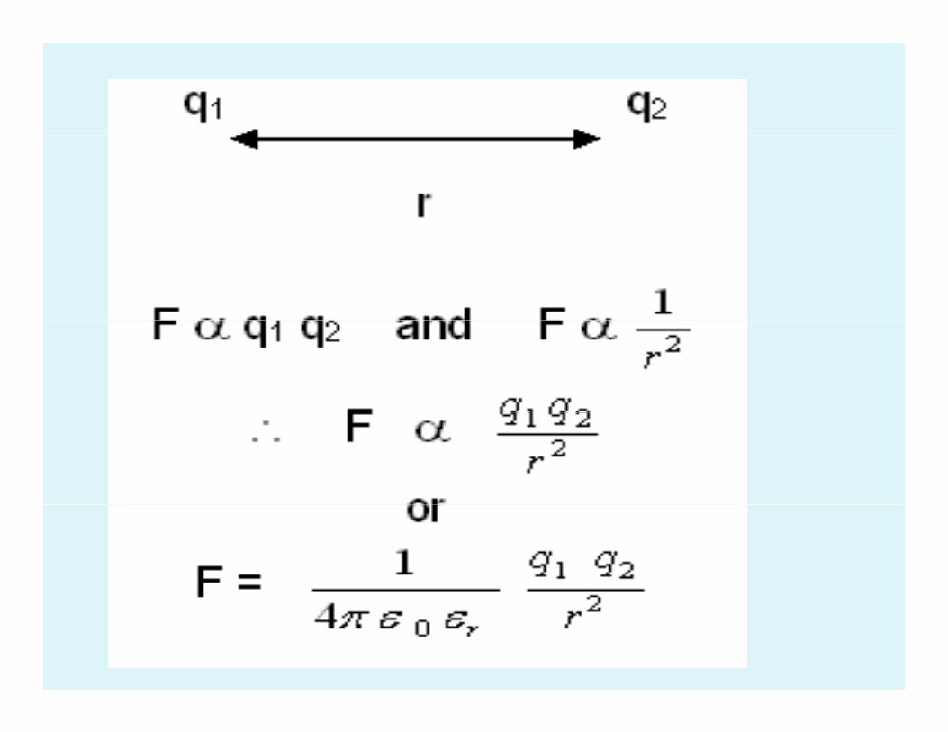
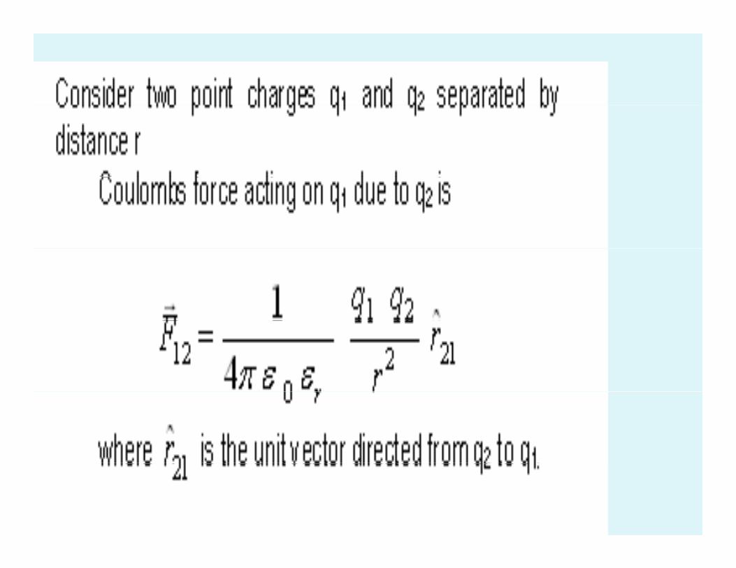
• Coulomb’s Law :The electro static force of attraction or repulsionof attraction or repulsion between any two point charges is directly proportional to the product of magnitudes of charges and g ginversely proportional to the square of the distance between them Theof the distance between them. The force act along the line joining the two chargestwo charges.
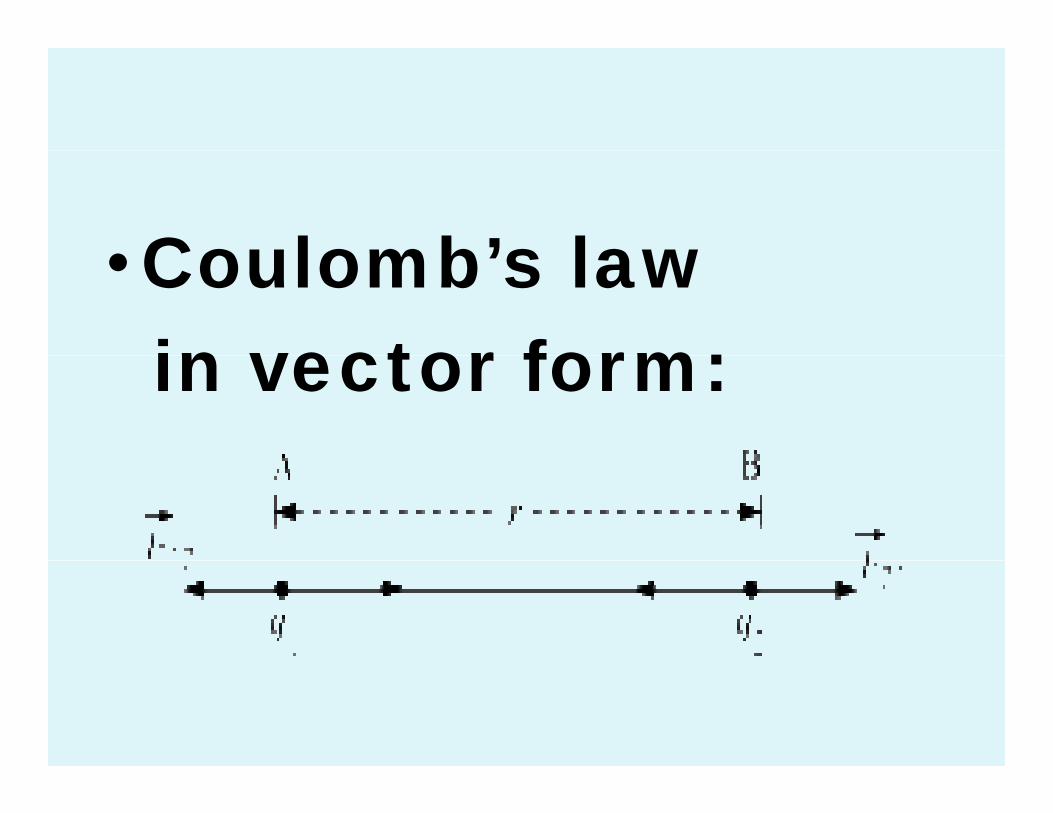
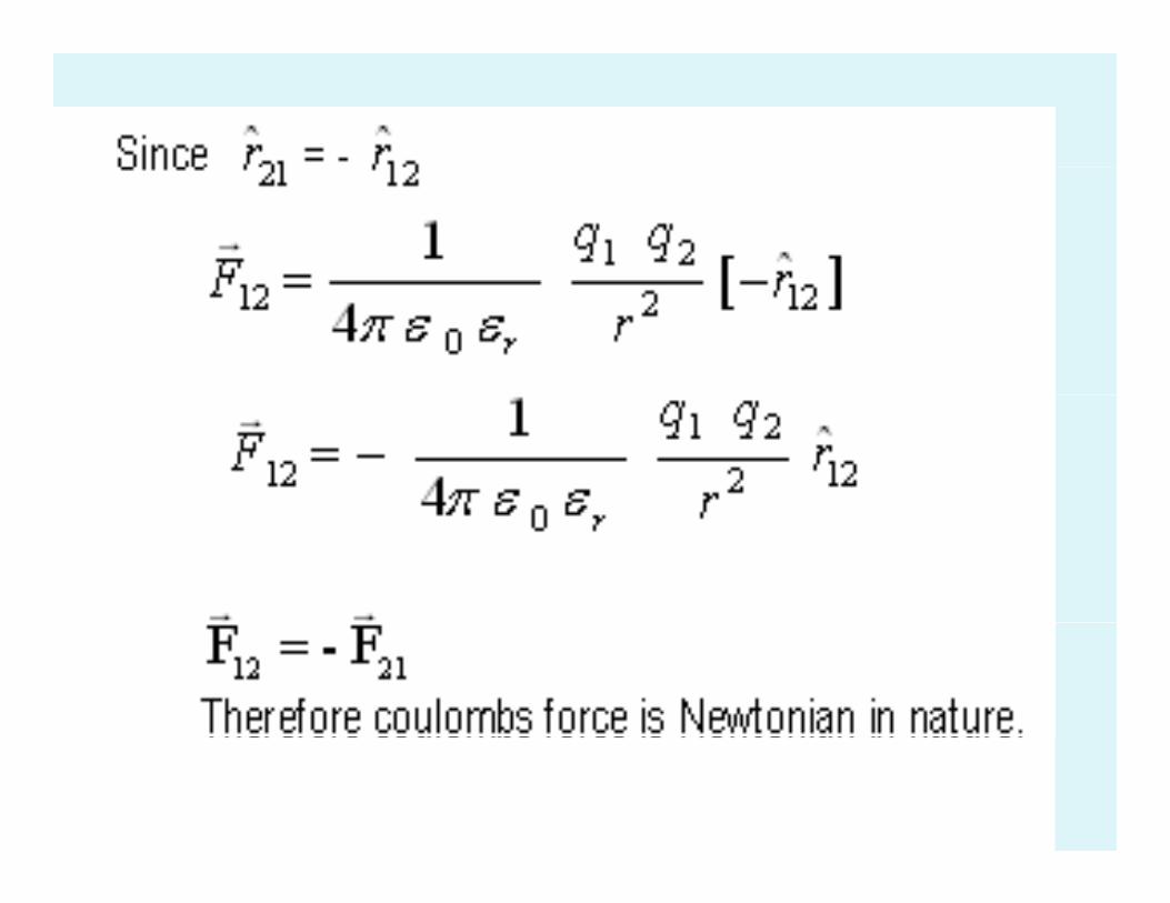
Coulomb’s law•Coulomb’s lawin vector form:in vector form:


D fi iti f• Definition of one coulomb:one coulomb:
• 1 coulomb is that charge which gwhen placed at a distance of 1
t i i fmeter in air or vacuum from an identical charge would repel it g pwith a force of 9 x 10 9 N.

• Dielectric constant ( K ) orDielectric constant ( K ) or
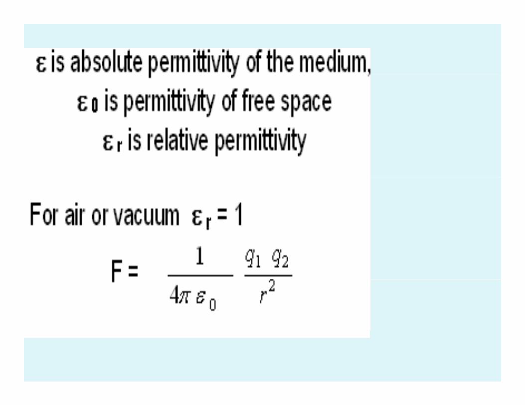
• Relative Permitivity ( ε r )• Dielectric constant or relative permitivity of the medium is thepermitivity of the medium is the ratio of force between two point charges placed at a certain distance in air to the force between same twoin air to the force between same two point charges placed at same di b i didistance but in medium.
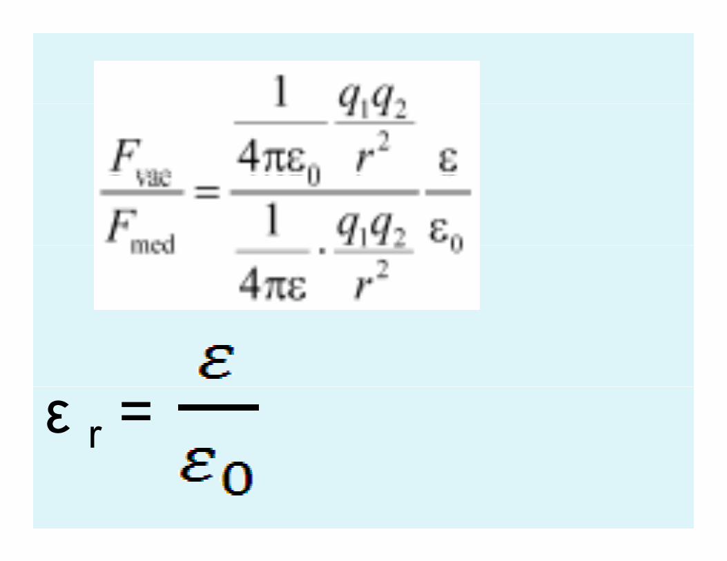
ε r =
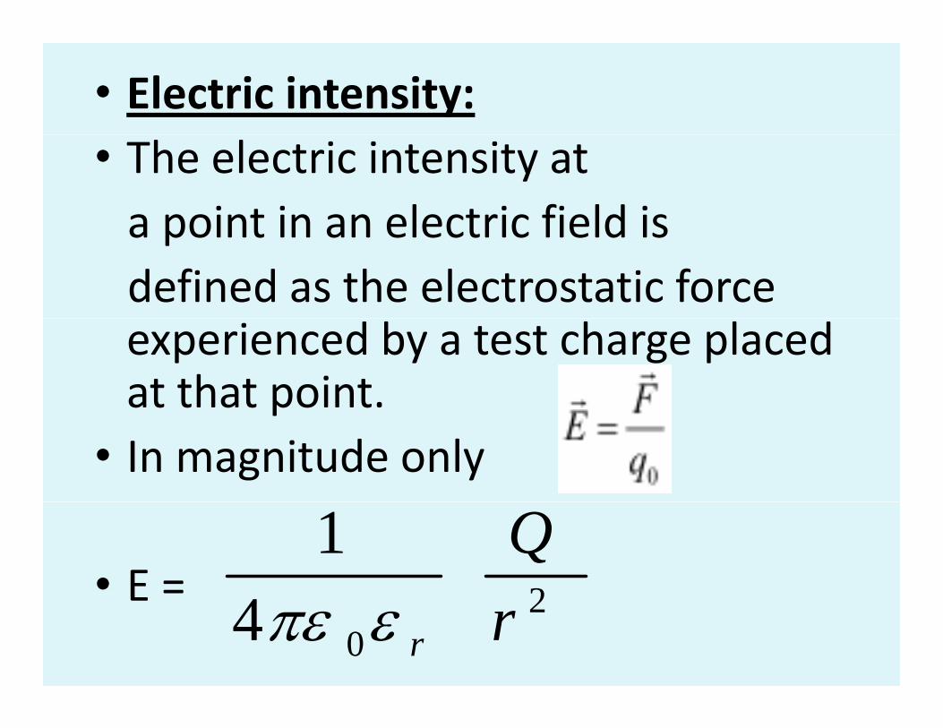
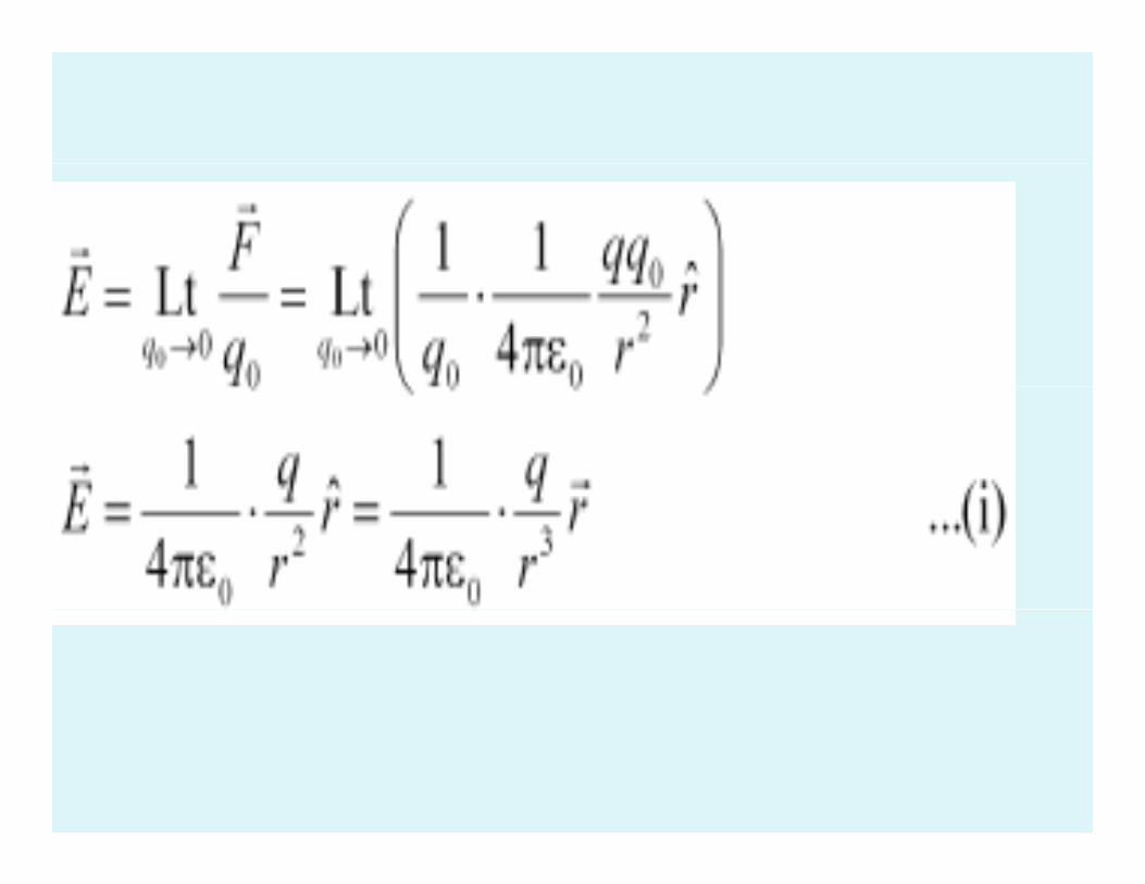
• Electric intensity:• The electric intensity at a point in an electric field isa point in an electric field isdefined as the electrostatic force experienced by a test charge placed at that point.p
• In magnitude only
• E = 21 Q
E 204 rrεπε

l• Electric intensity
i t titis a vector quantity.
Its S I unit is N C – 1Its S.I unit is N C 1
or V m ‐ 1 Its dimensionalor V m . Its dimensional formula is M 1 L 1 T ‐ 3 A ‐ 1
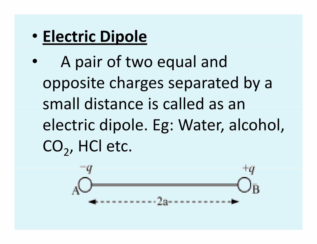
• Electric Dipole • A pair of two equal and opposite charges separated by a small distance is called as ansmall distance is called as an electric dipole. Eg: Water, alcohol, CO2, HCl etc.
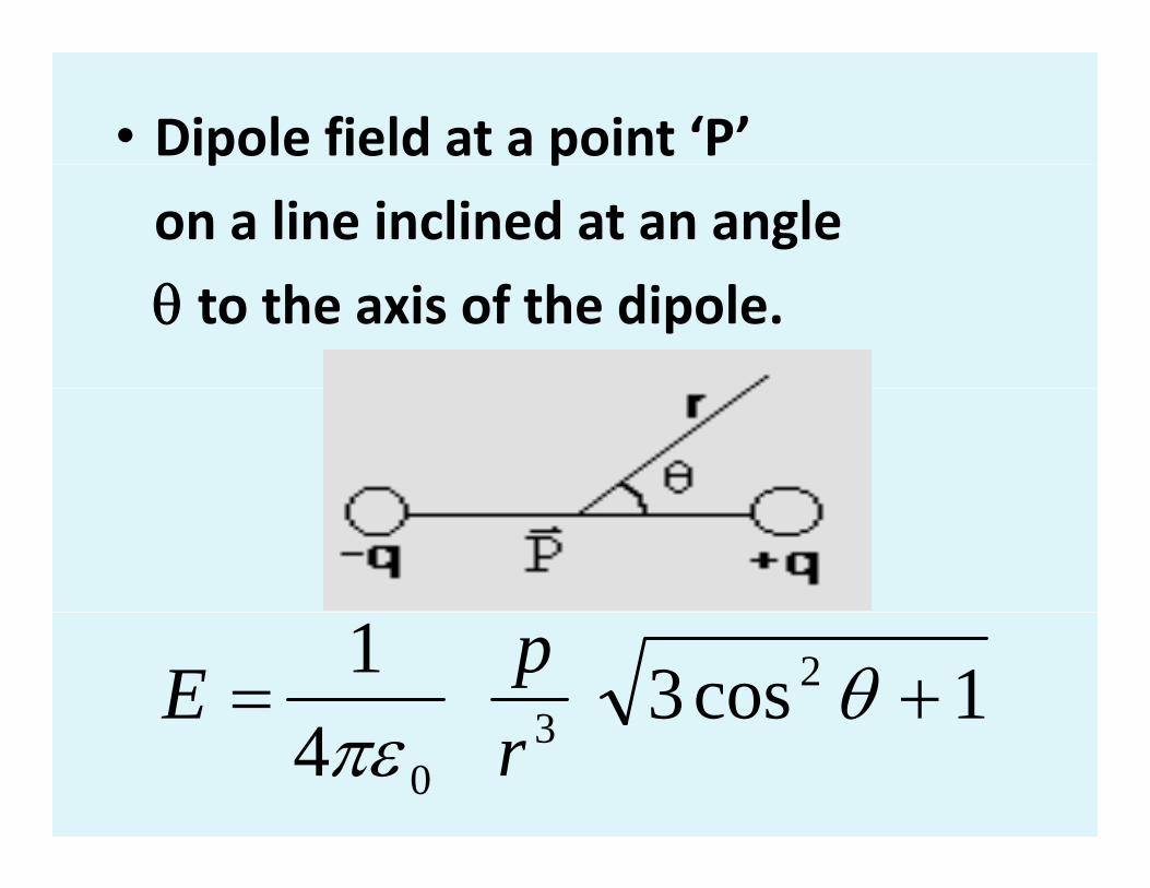
• Dipole field at a point ‘P’ p p
on a line inclined at an angle
θ to the axis of the dipole.
1cos31 23 += θpE
4 30πε r
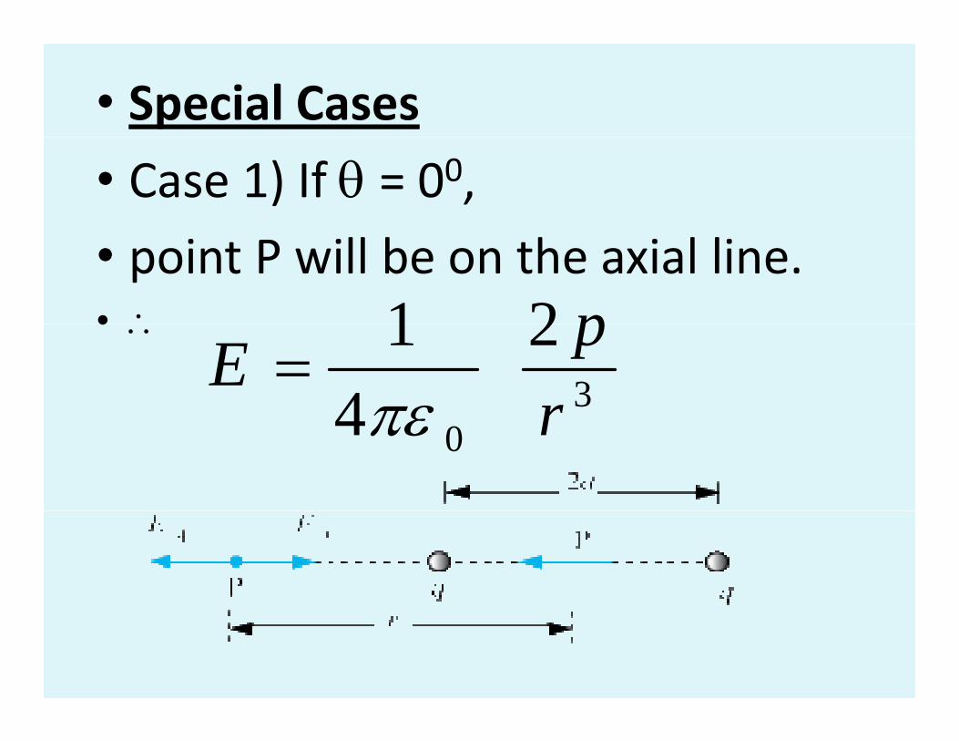
• Special Cases • Case 1) If θ = 00, • point P will be on the axial line.• ∴ 21 p• ∴
32
41
rpE
πε=
04 rπε
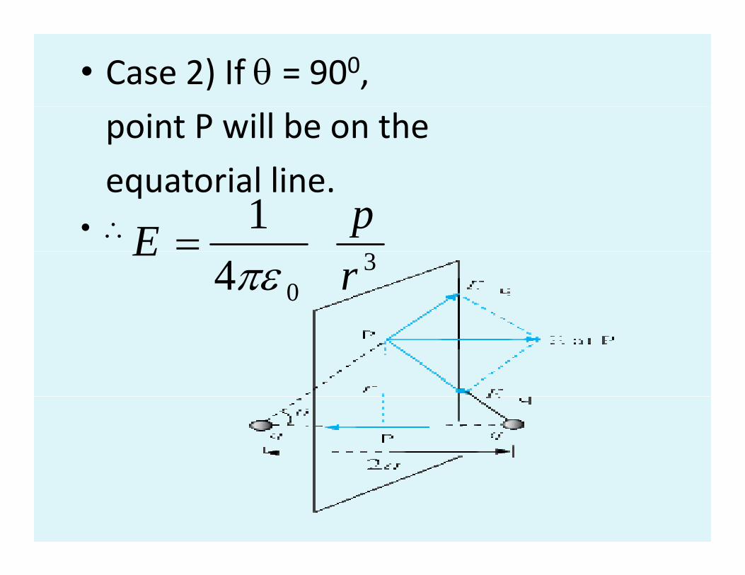
• Case 2) If θ = 900, point P will be on the
equatorial lineequatorial line.• ∴ 1 pE = 3
04 rE
πε
• Electric Dipole Moment
• Electric dipole moment
can be defined as the product ofcan be defined as the product of magnitude of either charge and dipole length.
• p = (q ) (2 a)p (q ) ( )
• Dipole moment is a vector quantity. Its S I it i C ( l b t ) ItS.I unit is C m (coulomb meter). Its dimensional formula is [M0L1T1A1].
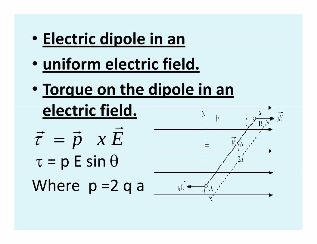
• Electric dipole in an p
• uniform electric field.
• Torque on the dipole in an l t i fi ldelectric field.
Exprrrτ
τ = p E sin θExp=τ
pWhere p =2 q a
• Electric dipole moment
in terms of torque
• By definition torque τ = p E sin θy q pp =
θτSinE
• If E = 1 unit and θ = 900 (Sin θ = 1) then p = τ.
• “The dipole moment is equal to the torque acting on a dipole placed q g p pperpendicular to the direction of uniform electric field of unit strength”electric field of unit strength .

• Dielectric Breakdown and• Dielectric Breakdown and • Dielectric strength g
• When a strong electric field is l d h d l happlied to the dielectric the
electrons, detach from the atoms / , /molecules and become free electrons This phenomenon iselectrons. This phenomenon is known as dielectric breakdown.
Th i l f• The maximum value of
applied electric field pp
above which dielectric breakdown takes place is known as dielectric strengthplace is known as dielectric strength.
• Dielectric strength is expressed in terms of kilo volt per millimeter.
• (k V mm‐1)(k V mm )
• Electric field lines of force• The concept of electric
lines of force was introduced by Michael FaradayMichael Faraday.
• An electric line of force is anAn electric line of force is an imaginary path along which a
hpositive test charge moves or tends to move in the electric field.tends to move in the electric field.
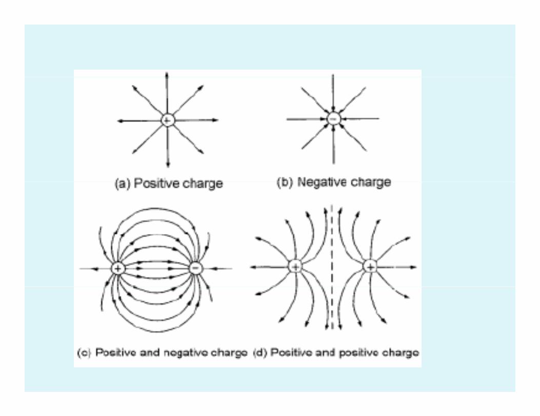
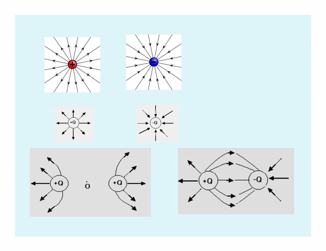

• Properties of Electric lines of force
• 1. Electric lines of force start frompositive charge and end at negative charge. g
• 2. Two electric lines of force never h h f h d hintersect each other. If they do so then
at the point of intersection there will pbe two directions of electric field. Which is not possibleWhich is not possible.
• 3 The tangent drawn to a line• 3. The tangent drawn to a line
at a point gives the direction of
electric field at that point.
• 4 Electric lines of force never enter into• 4. Electric lines of force never enter into a conductor. But they can pass through a di l t idielectric.
• 5. The electric lines of force are perpendicular to the surface of charged conductor.conductor.

• 6. Electric lines of force can 6. lectric lines of force can
stretch or contract length wise.
• 7. In uniform electric field, electric lines of force are parallel to eachlines of force are parallel to each other.
• In strong electric field, electric lines of force are crowdedlines of force are crowded.
• In weak electric field, electric lines of force are spread apart.
• Electric flux ( φ )( φ )• The electric flux
through a surface is gdefined as the total number of electric lines of f llforce passing normally through that surfacethrough that surface.

Gauss’ Theorem
• Gauss theorem states that
h l l i fl h hthe total electric flux through
any closed surface is equal to times 0
1εy q
the total charge enclosed by that surface. 0
• φ = Σ q 1ε 0ε
l i i i i• Electric intensity at a point
near an irregular shaped
charged conductor ( 4 marks )
El i i i i• Electric intensity at a point
near (Just outside) the surface of a charged spherical conductor. ( 4 marks )
El t i P t ti l• Electric Potential • Electric potential at a point in an p pelectric field is defined as the potential energy possessed by a unitpotential energy possessed by a unit positive charge placed at that point and it is given by the work done inand it is given by the work done in bringing a unit positive charge from i fi i h i i hinfinity to that point against the direction of electric field.
• V =
El t i t ti l i l• Electric potential is a scalar quantity. Its S.I unit is J C‐1 or V q y(volt). Its dimensional formula is [M1L2T 3A 1][M1L2T‐3A‐1].

• Definition of 1 volt.Definition of 1 volt. • Electric potential at a point in an electric field is id t b lt if j lsaid to be one volt if one joule
of work is done in bringing aof work is done in bringing a charge of one coulomb from i fi it t th t i t i tinfinity to that point against the direction of electric field.the direction of electric field.
• Relation between electric intensity
d l i i land electric potential.
The force experienced by test charge is
F = q0 E.
• Electric potential at A = VElectric potential at A V.
• Electric potential at B = V + dV
W k d ( i l diff ) ( h )• ∴Work done = (potential difference) (charge) dW = ( V + dV – V ) q0
• dW = (dV) q0 … [1]
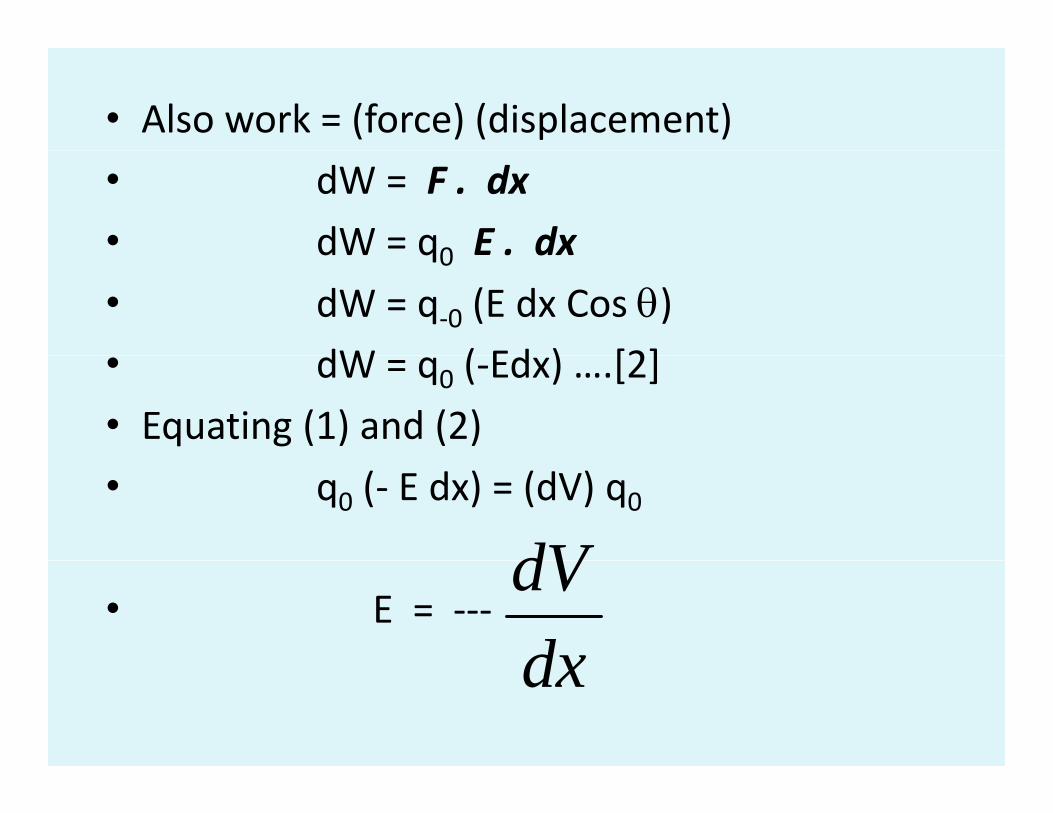
• Also work = (force) (displacement)
• dW = F . dx
• dW = q0 E . dxdW q0 E . dx
• dW = q‐0 (E dx Cos θ) dW ( Ed ) [2]• dW = q0 (‐Edx) ….[2]
• Equating (1) and (2)
• q0 (‐ E dx) = (dV) q0
dV• E = ‐‐‐
dxdVdx

• Thus the electric intensity at a pointThus, the electric intensity at a point
in an electric field is negative potential gradient at that point.
• The negative sign indicates that the• The negative sign indicates that the direction of E is in the direction of decreasing electric potential
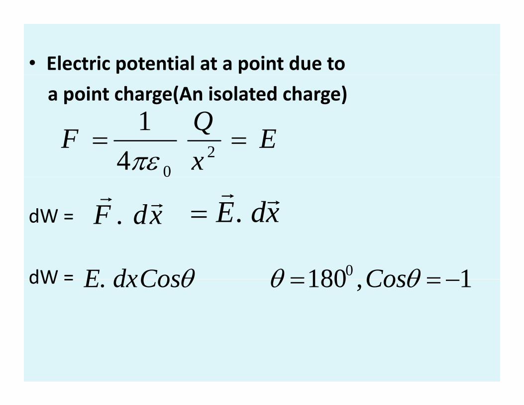
• Electric potential at a point due to
a point charge(An isolated charge)Q1 ExQF == 2
041πε
dW = xdF rr. xdE rr
.=
dW = 11800 == θθθ CosCosdxEdW = 1,180. −== θθθ CosCosdxE
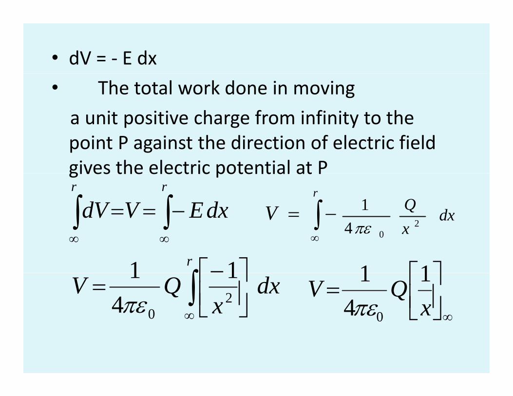
• dV = ‐ E dx
• The total work done in moving
a unit positive charge from infinity to thea unit positive charge from infinity to the point P against the direction of electric field gives the electric potential at Pgives the electric potential at P
∫∫ −==rr
dxEVdV dxQ24
1∫ −=r
V∫∫∞∞
x 204πε∫
∞
r
∫⎤⎡−11 ⎤⎡11dx
xQV ∫
∞⎥⎦⎤
⎢⎣⎡= 2
0
14
1πε
∞⎥⎦⎤
⎢⎣⎡=x
QV 14
1
0πε
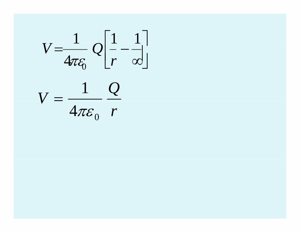
⎤⎡ 111 Q ⎥⎦⎤
⎢⎣⎡
∞−=
1141
0 rQV
πε
QV 1=
rV
04πε

El t t ti t ti l• Electro static potential energy of a system of chargesenergy of a system of charges
• Electrostatic potential energy of a system of point charges is defined as the amount of workdefined as the amount of work done in bringing the individual h f th i t t f t tcharges from their state of rest at infinity to form the system.y y
• Electrical Capacitance
or capacity
• When charges are added to a• When charges are added to a conductor its potential increase.
Thus, electric potential of a conductor is directly proportional to the charge on it.directly proportional to the charge on it.
• ∴ V ∝ Q or Q ∝ V or Q = C V Where C is known as electrical capacitance or capacity of a conductor . p p y
• Capacitance of a conductor is its ability to store the
l t i h d it ielectric charges and it is
given by the ratio of charge addedgiven by the ratio of charge added
to the conductor to rise in potential of a conductor. QC =
VC =
• Capacitance is aCapacitance is a
scalar quantity. Its S.I unit
is farad (F). Its dimensional formula is [M‐1 L‐2 T4 A2]is [M 1 L 2 T4 A2].
Definition of one farad ( 1 F )
If Q 1C d V 1 lt• If Q = 1C and V = 1 volt
then C = 1 F. Qthen C 1 F.
VQC =
Capacitance of a conductor is said to pbe 1 farad if one coulomb of charge added to the conductor raises itsadded to the conductor raises its potential by one volt.
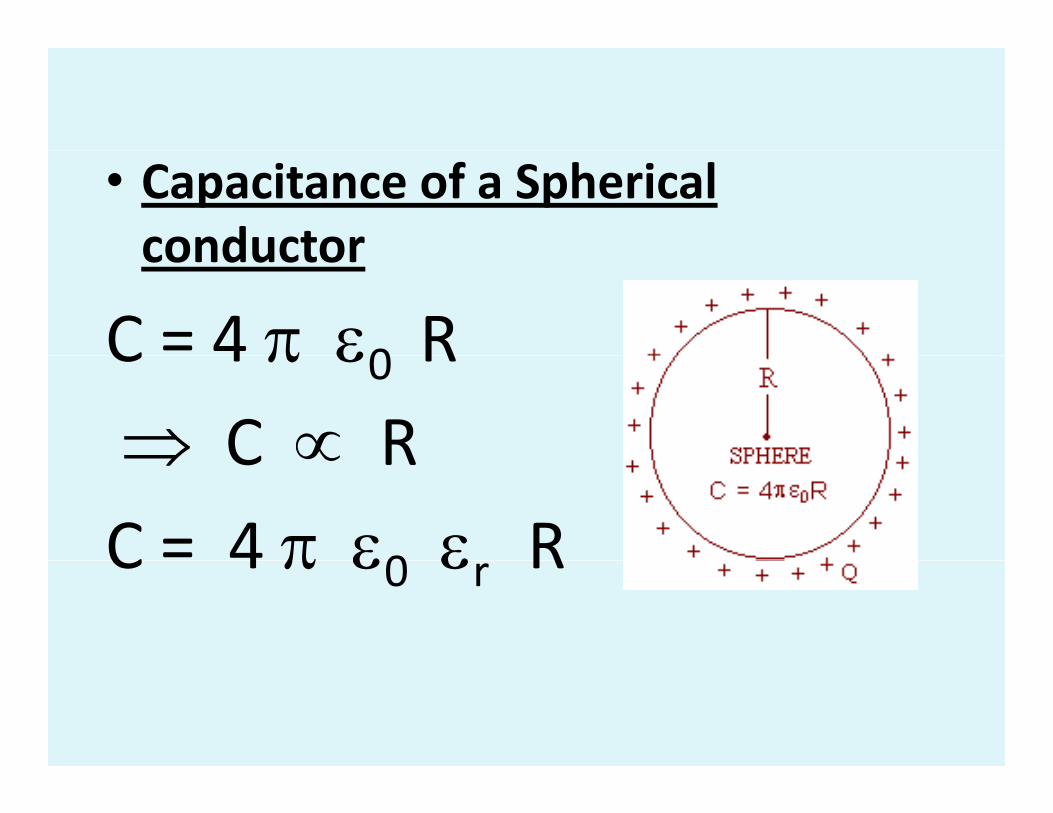
• Capacitance of a Spherical conductorconductor
C = 4 π ε0 RC 4 π ε0 R ⇒ C ∝ R⇒ C ∝ R
C = 4 π ε0 ε RC 4 π ε0 εr R

Capacitor: It is a device
used to store electric charges (Electrical energy)(Electrical energy).
In its simplest form it has two closely lying parallel conductors separated by certain distance and the spacecertain distance and the space between the conductors can be filled by a dielectric materialby a dielectric material.

• Principle of a capacitor ( 4 marks )
• Capacitance of a parallel plate capacitor
• C = d
A0ε
• If the space between the plates
i fill d b di l i di
d
• is filled by a dielectric medium
• of dielectric constant εr then
C = Arεε 0
d
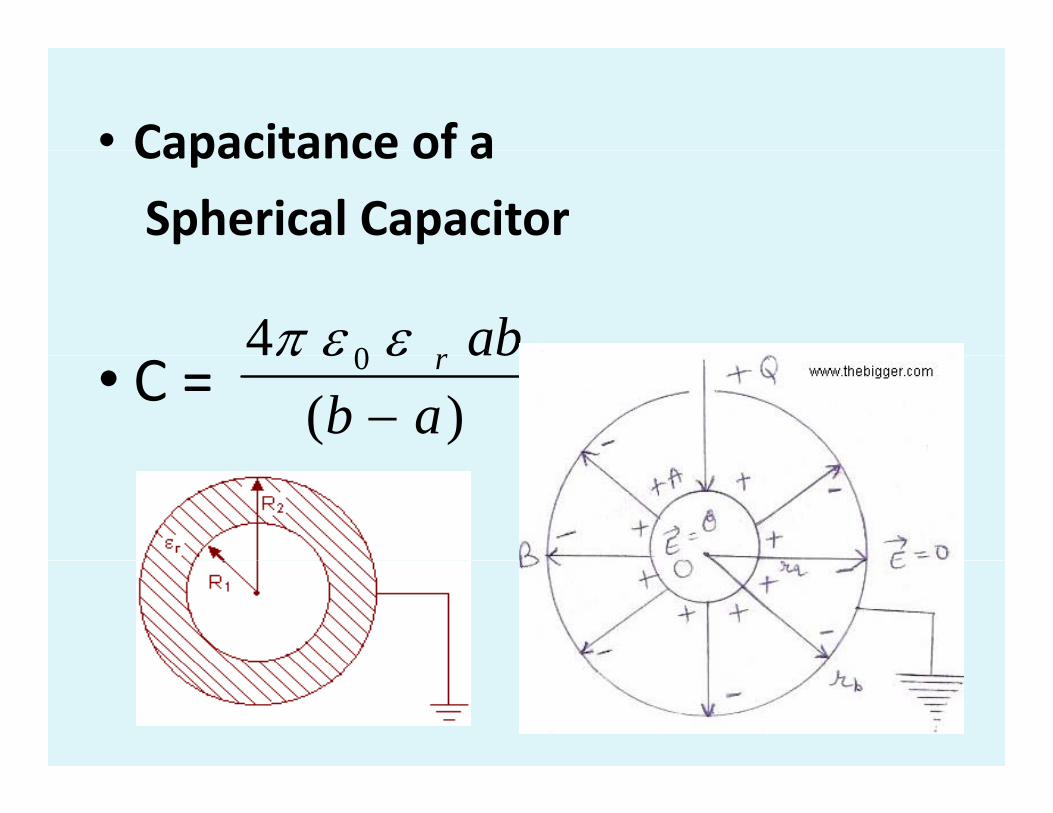
• Capacitance of aCapacitance of a
Spherical Capacitor
4 0 abrεεπ• C = )(
0
ababr
−εεπ
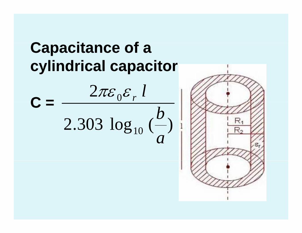
C it fCapacitance of a cylindrical capacitor
2 0 lrεπεy p
C =)(log303.2 10
bC = )(g10 a
• The capacitance of spherical capacitor can be increased 1 By increasing the radii of the1. By increasing the radii of the spheres. 2. By reducing the space between the spheresthe spheres. 3. By introducing a dielectric material of higher value of εr in between the spheres.between the spheres.
• The capacitance of cylindrical capacitor is increased
• 1 By increasing the length of the• 1. By increasing the length of the cylinder
• 2. By introducing a dielectric material of higher value of ε . in between theof higher value of εr. in between the plates. 3 B d i th b t• 3. By decreasing the space between the cylinders
• Dielectric constant in terms of
i f icapacitance of a capacitor
• The dielectric constant or relative permitivity of a medium can be defined as the ratio of capacitance of a capacitor with dielectric material in between its parallel plates, separated by certain distance to the capacitance of a capacitor with air in between the parallel plates separated by the same distance.
• K = Cm / Ca = εr.m / a r

• Energy stored in a capacitor b h h d d• Let q be the charge deposited
and V be the potential differenceand V be the potential difference between the plates. Then the
i f h i icapacitance of the capacitor is
• C = q / V ∴V = q / CC = q / V ∴V = q / C The amount of work done in transferring an additional charge
dq is d W = V d qdq is d W = V d q.
• Therefore total work done
in transferring complete charge
to the capacitor isto the capacitor is
∫ d W = ∫ V dq
W = ∫ (q / C) dq = 1 / C [q2 / 2 ]• This total work done in transferring the charge• This total work done in transferring the charge is stored in a capacitor as electrostatic energy. Therefore energy stored in a capacitor isTherefore, energy stored in a capacitor is
• U = ½ Q2/C. or U = ½ C V2 or U = ½ QV.
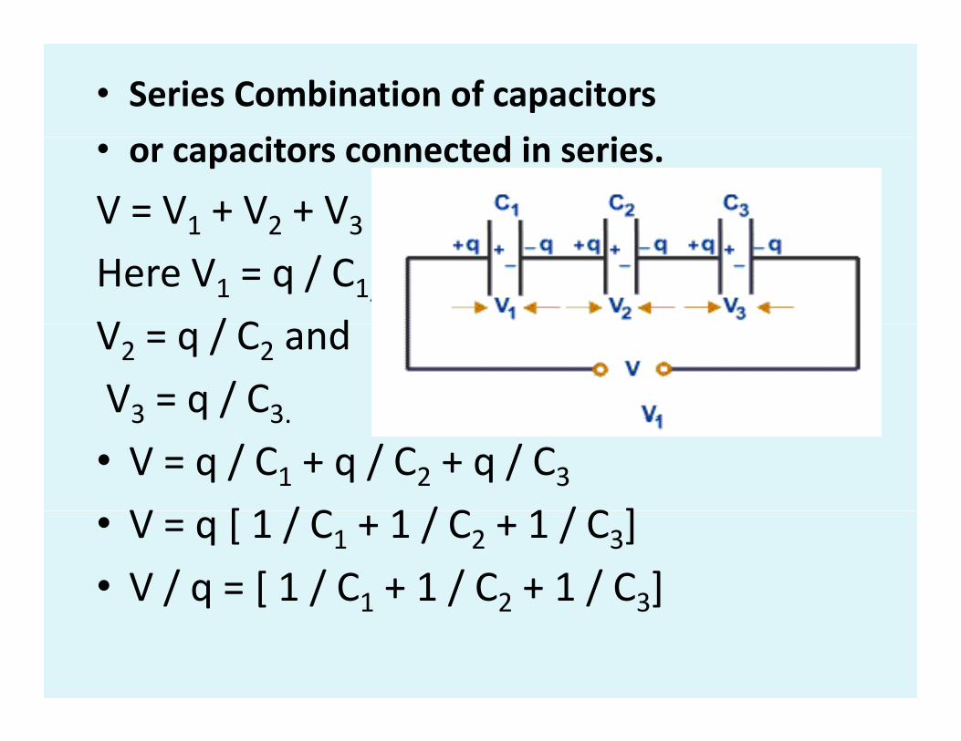
• Series Combination of capacitors
i d i i• or capacitors connected in series.
V = V1 + V2 + V31 2 3
Here V1 = q / C1,V / C dV2 = q / C2 and
V3 = q / C33 q / 3.
• V = q / C1 + q / C2 + q / C3V [ 1 / C 1 / C 1 / C ]• V = q [ 1 / C1 + 1 / C2 + 1 / C3]
• V / q = [ 1 / C1 + 1 / C2 + 1 / C3]/ q [ / 1 / 2 / 3]

• If the three capacitors connectedIf the three capacitors connected
in series are replaced by a single
i l i f i C hequivalent capacitor of capacitance Cs then.
• q = Cs V OR 1 / Cs = V / q
Equating we get
• 1 / C = [ 1 / C1 + 1 / C2 + 1 / C3]1 / Cs [ 1 / C1 + 1 / C2 + 1 / C3]
• Thus, the reciprocal of effective capacitance of capacitors connected in series is equal to thecapacitors connected in series is equal to the sum of reciprocals of individual capacitances.
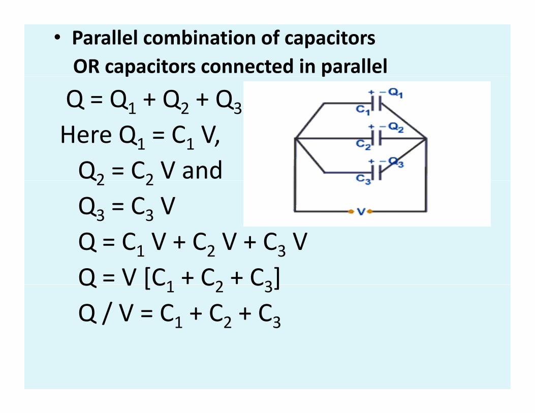
• Parallel combination of capacitors OR capacitors connected in parallelp p
Q = Q1 + Q2 + Q3
H Q C VHere Q1 = C1 V, Q2 = C2 V and Q2 2
Q3 = C3 V Q C C CQ = C1 V + C2 V + C3 V Q = V [C1 + C2 + C3]Q V [C1 C2 C3]Q / V = C1 + C2 + C3

If the three capacitors connectedp
in parallel are replaced by a single
equivalent capacitor of capacitance C thenequivalent capacitor of capacitance Cp then.
• Q = Cp V Q / V = CpEquating we get.
Cp = C1 + C2 + C3. p 1 2 3
• Thus, the equivalent capacitance or the effective capacitance of number of capacitorseffective capacitance of number of capacitors connected in parallel is equal to the sum of individual capacitancesindividual capacitances.
• Uses of Capacitors
• Capacitors are used
• 1) To store electrical energy / Charge• 1) To store electrical energy / Charge.
• 2) To produce strong electric fields in small space.
• 3) In voltage stabilizer to provide steady3) In voltage stabilizer to provide steady D.C voltage.
4) T li i k i i i i• 4) To eliminate sparks in ignition system of automobiles.
• 5) To measure very small current
of the order of micro ampere.
• 6) To measure very high resistance• 6) To measure very high resistance
of the order of mega ohm.
• 7) To measure self inductance and mutual inductance.mutual inductance.
• 8) As potential dividers.
• 9) In AC circuits to control electric current.