香港考試局 - 迦密聖道中學 carmel holy word...
TRANSCRIPT
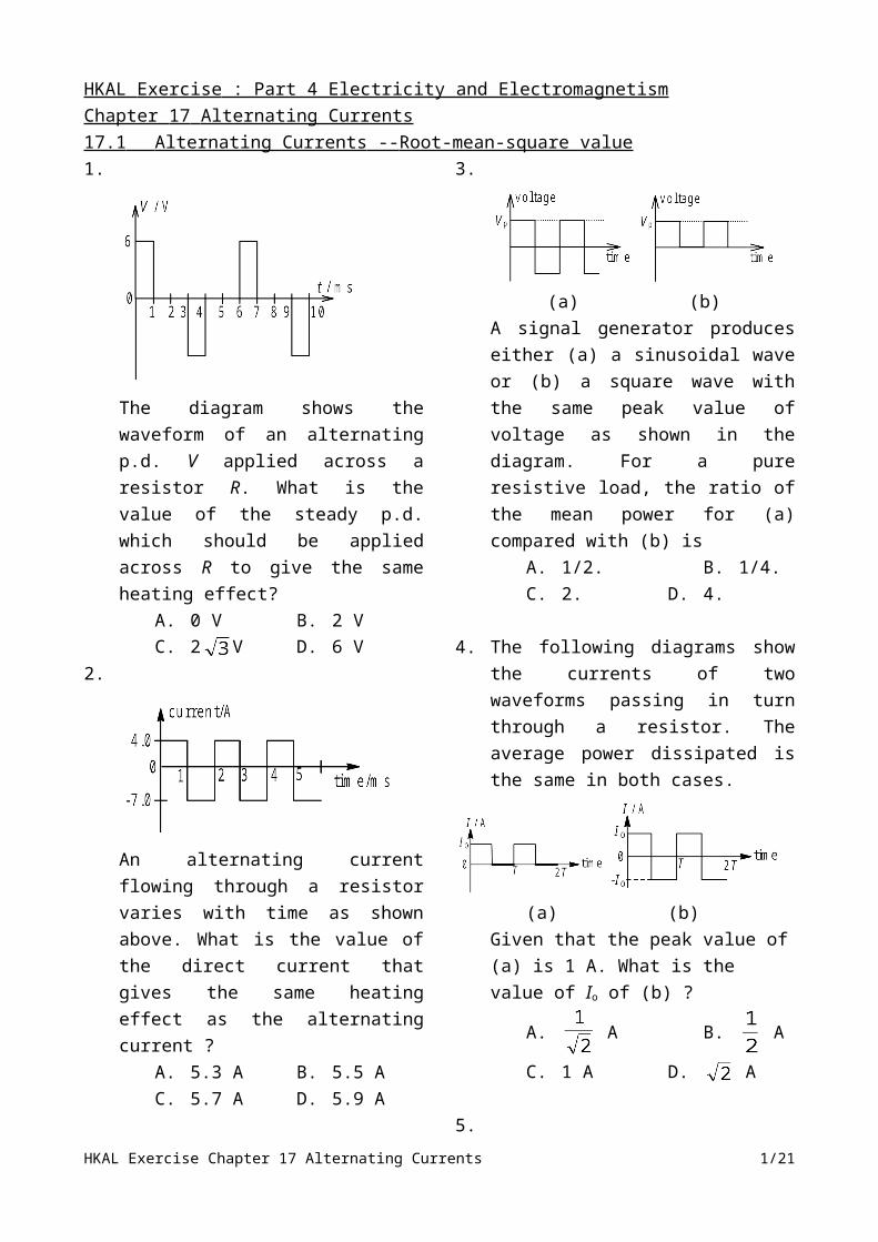
HKAL Exercise : Part 4 Electricity and Electromagnetism Chapter 17 Alternating Currents 17.1 Alternating Currents -- Root-mean-square value 1.
The diagram shows the waveform of an alternating p.d. V applied across a resistor R. What is the value of the steady p.d. which should be applied across R to give the same heating effect?
A. 0 V B. 2 VC. 2 V D. 6 V
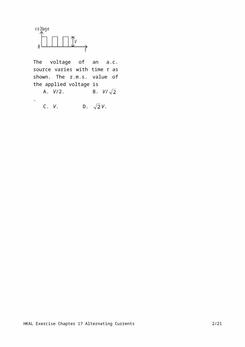
2.
An alternating current flowing through a resistor varies with time as shown above. What is the value of the direct current that gives the same heating effect as the alternating current ?
A. 5.3 A B. 5.5 AC. 5.7 A D. 5.9 A
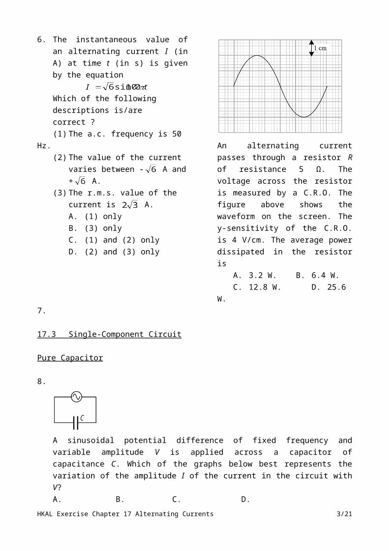
3.
(a) (b)
A signal generator produces either (a) a sinusoidal wave or (b) a square wave with the same peak value of voltage as shown in the diagram. For a pure resistive load, the ratio of the mean power for (a) compared with (b) is
A. 1/2. B. 1/4.C. 2. D. 4.
4. The following diagrams show the currents of two waveforms passing in turn through a resistor. The average power dissipated is the same in both cases.
(a) (b)Given that the peak value of (a) is 1 A. What is the value of Io of (b) ?
A. A B. A
C. 1 A D. A
5.
The voltage of an a.c. source varies with time t as shown. The r.m.s. value of the applied voltage is
A. V/2. B. V/ .C. V. D. V.
HKAL Exercise Chapter 17 Alternating Currents 1/21
6. The instantaneous value of an alternating current I (in A) at time t (in s) is given by the equation
Which of the following descriptions is/are correct ?(1) The a.c. frequency is 50 Hz.(2) The value of the current varies
between - A and + A.(3) The r.m.s. value of the current is
A.A. (1) onlyB. (3) onlyC. (1) and (2) onlyD. (2) and (3) only
7.
An alternating current passes through a resistor R of resistance 5 Ω. The voltage across the resistor is measured by a C.R.O. The figure above shows the waveform on the screen. The y-sensitivity of the C.R.O. is 4 V/cm. The average power dissipated in the resistor is
A. 3.2 W. B. 6.4 W.C. 12.8 W. D. 25.6 W.
17.3 Single-Component Circuit
Pure Capacitor
8.
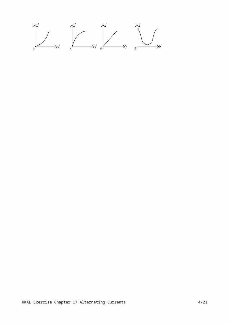
A sinusoidal potential difference of fixed frequency and variable amplitude V is applied across a capacitor of capacitance C. Which of the graphs below best represents the variation of the amplitude I of the current in the circuit with V?A. B. C. D.
HKAL Exercise Chapter 17 Alternating Currents 2/21
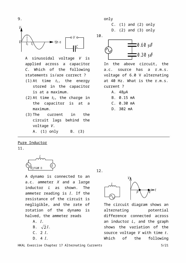
9.
A sinusoidal voltage V is applied across a capacitor C. Which of the following statements is/are correct ?(1) At time t1, the energy stored in the
capacitor is at a maximum.(2) At time t2, the charge in the capacitor
is at a maximum.(3) The current in the circuit lags behind
the voltage V.A. (1) only B. (3) onlyC. (1) and (2) only
D. (2) and (3) only10.
In the above circuit, the a.c. source has a r.m.s. voltage of 6.0 V alternating at 40 Hz. What is the r.m.s. current ?
A. 48μAB. 0.15 mAC. 0.30 mAD. 302 mA
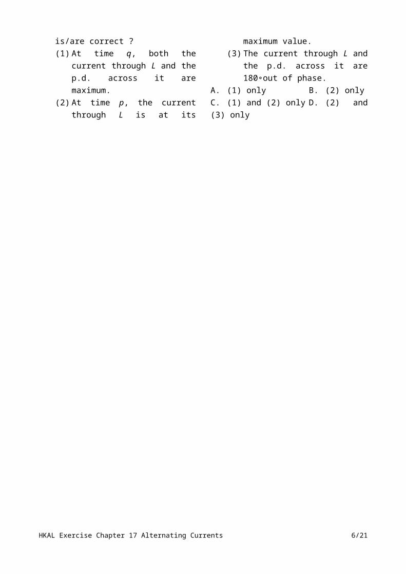
Pure Inductor11.
A dynamo is connected to an a.c. ammeter X and a large inductor L as shown. The ammeter reading is I. If the resistance of the circuit is negligible, and the rate of rotation of the dynamo is halved, the ammeter reads
A. I.B. I.
C. 2 I.D. 4 I.
12.
The circuit diagram shows an alternating potential difference connected across an inductor L, and the graph shows the variation of the source voltage V with time t. Which of the following is/are correct ?(1) At time q, both the current through L
and the p.d. across it are maximum.(2) At time p, the current through L is at
its maximum value.(3) The current through L and the p.d.
across it are 180∘out of phase.A. (1) only B. (2) onlyC. (1) and (2) only D. (2) and (3) only
HKAL Exercise Chapter 17 Alternating Currents 3/21
17.4 Two-Component Circuit
Impedance13. Which of the following physical quantities
take(s) the unit ohm (Ω) ?(1) resistance(2) Inductance(3) Capacitance
A. (1) onlyB. (3) onlyC. (1) and (2) onlyD. (2) and (3) only
14. The impedance of a solenoid depends on(1) the resistance of the solenoid.(2) the frequency of the applied a.c.
voltage.(3) the inductance of the solenoid.
A. (1) onlyB. (3) onlyC. (2) and (3) onlyD. (1), (2) and (3)
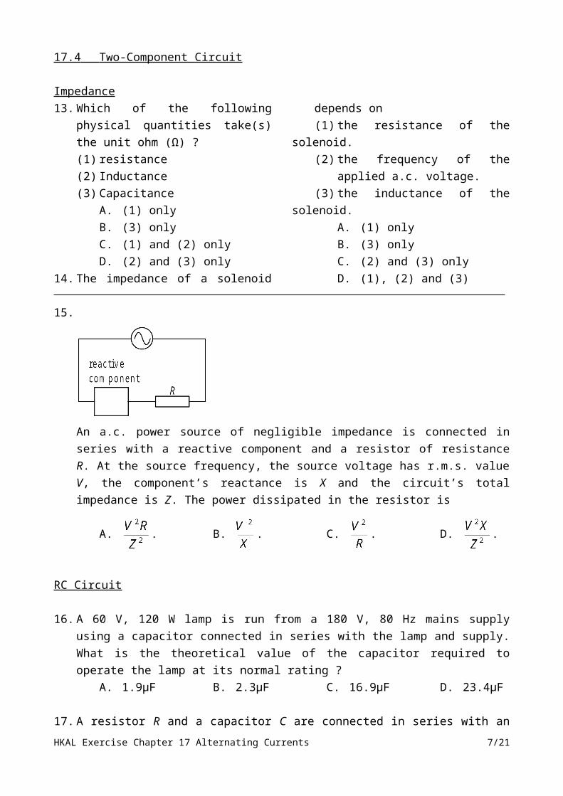
15.
An a.c. power source of negligible impedance is connected in series with a reactive component and a resistor of resistance R. At the source frequency, the source voltage has r.m.s. value V, the component’s reactance is X and the circuit’s total impedance is Z. The power dissipated in the resistor is
A. . B. . C. . D. .
RC Circuit
16. A 60 V, 120 W lamp is run from a 180 V, 80 Hz mains supply using a capacitor connected in series with the lamp and supply. What is the theoretical value of the capacitor required to operate the lamp at its normal rating ?
A. 1.9μF B. 2.3μF C. 16.9μF D. 23.4μF
17. A resistor R and a capacitor C are connected in series with an a.c. supply. The r.m.s. applied voltage and the r.m.s. current are V and I, respectively. If the resistance of R is one fourth of the total impedance of the circuit, the power consumed in the circuit will be
A. IV/10. B. IV/4. C. IV/2. D. 16IV/17.
HKAL Exercise Chapter 17 Alternating Currents 4/21
18.
In the above circuit, a signal generator of fixed output voltage is connected in series with a resistor R and capacitor C. When the frequency of the signal generator is gradually increased, which of the following is the correct variation of the ammeter and the voltmeter readings ?
Ammeter reading Voltmeter readingA. increases and then decreases decreases throughoutB. increases and then decreases decreases and then increasesC. increases throughout increases throughoutD. increases throughout decreases throughout
19.
A capacitor C and a resistor R are connected in series to an a.c. source of constant output voltage. Which of the following statements is/are INCORRECT ?(1) The impedance of the circuit
increases when the frequency increases.
(2) The power factor of the circuit increases when the frequency decreases.
(3) The applied voltage leads the current.A. (1) onlyB. (1) and (2) onlyC. (2) and (3) onlyD. (1), (2) and (3)
20.
In the circuit shown, the voltages, across the resistor and the capacitor are respectively fed to the input terminals Y1 and Y2 of a dual trace CRO where E is the common earth terminal. Which of the following pairs of traces could be obtained ? (The trace of Y1 is represented by a solid curve and the trace of Y2 is represented by a dotted one.)
A. B.
C. D.
HKAL Exercise Chapter 17 Alternating Currents 5/21
21. A black box, known to contain an electrical device, is connected in series with a resistor R. The
following circuit is set up:
The pattern observed on the double beam C.R.O. is shown below:
The electrical device inside the box isA. a transistor. B. a capacitor. C. an inductor. D. a resistor.
22. A sinusoidal alternating voltage of 1.3 V r.m.s. and frequency 25 Hz is applied to the circuit shown in Figure 22.1, which consists essentially of a resistor R and capacitor C connected in series. The ammeter reads 0.1 A r.m.s. The two voltmeters V1 and V2 are designed to read r.m.s. voltages.
Figure 22.1 (a) If the resistance of R is 12 Ω, calculate the readings of the voltmeters V1 and V2, and
account for the fact that they do not add up to give 1.3 V. (3 marks)
HKAL Exercise Chapter 17 Alternating Currents 6/21
(b) On the spaces provided on the next page, and with the scales chosen as shown, sketch two cycles of(i) the time-variation of the voltage across R,
(ii) the corresponding time-variation of the voltage across C, and
(iii) the corresponding time-variation of the voltage across R and C.
(5 marks)(c) (i) Explain, without making any detailed calculations, how you would expect the
reading of the ammeter to change when the frequency of the applied alternating voltage is
HKAL Exercise Chapter 17 Alternating Currents 7/21

increased if the amplitude is kept constant.
(ii) What is the maximum r.m.s. value of the current in the circuit that could be obtained by adjusting the frequency of the voltage if the amplitude is kept constant? Explain briefly.
(4 marks)
23. (a) Two conductors, a metal rod and a hollow cylindrical conductor, are arranged coaxially. Figure 23.1 shows their cross-section. The inner and outer conductors are charged with +Q and –Q respectively, which is distributed uniformly on their surfaces. Draw the resulting electric field lines. (1 mark)
Figure 23 .1 (b) Figure 23.2 shows a coaxial cable. The cable consists of an inner conductor, an insulating
layer, an outer conductor and a protective layer.
Figure 23 .2 (i) The cable can be represented as conductors AB and A’B’ in a circuit diagram. The
cable can be treated as a capacitor when the inner and outer conductors are taken as the positive and negative plates. To measure its capacitance per unit length C0, the cable is connected in series with an a.c. source and a 10 kΩ resistor as shown in Figure 23.3. The frequency of the source is 100 kHz. The r.m.s. voltage across the resistor is found to be 1.80 V when that of the source is 2.00 V.
HKAL Exercise Chapter 17 Alternating Currents 8/21

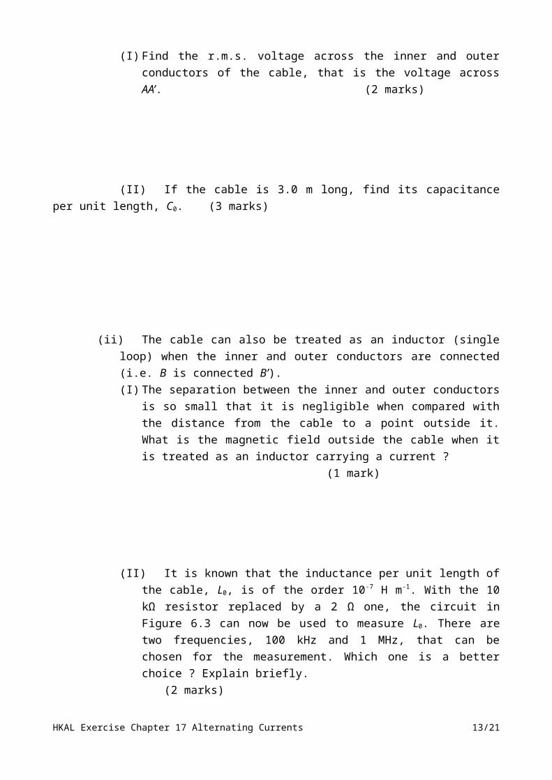
Figure 23.3(I) Find the r.m.s. voltage across the inner and outer conductors of the cable, that is
the voltage across AA’. (2 marks)
(II) If the cable is 3.0 m long, find its capacitance per unit length, C0. (3 marks)
(ii) The cable can also be treated as an inductor (single loop) when the inner and outer conductors are connected (i.e. B is connected B’).(I) The separation between the inner and outer conductors is so small that it is
negligible when compared with the distance from the cable to a point outside it. What is the magnetic field outside the cable when it is treated as an inductor carrying a current ? (1 mark)
(II) It is known that the inductance per unit length of the cable, L0, is of the order 10-7 H m-1. With the 10 kΩ resistor replaced by a 2 Ω one, the circuit in Figure 6.3 can now be used to measure L0. There are two frequencies, 100 kHz and 1 MHz, that can be chosen for the measurement. Which one is a better choice ? Explain briefly. (2 marks)
HKAL Exercise Chapter 17 Alternating Currents 9/21

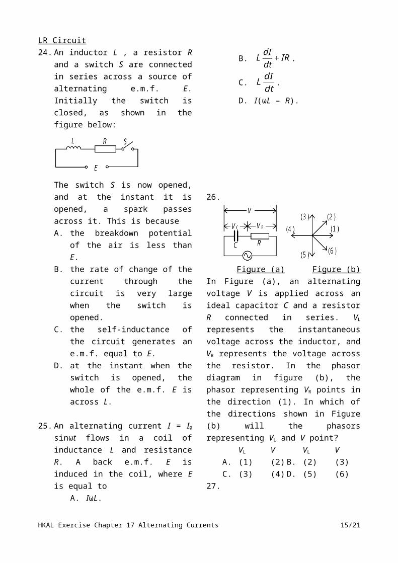
LR Circuit24. An inductor L , a resistor R and a switch S
are connected in series across a source of alternating e.m.f. E. Initially the switch is closed, as shown in the figure below:
The switch S is now opened, and at the instant it is opened, a spark passes across it. This is becauseA. the breakdown potential of the air is
less than E.B. the rate of change of the current
through the circuit is very large when the switch is opened.
C. the self-inductance of the circuit generates an e.m.f. equal to E.
D. at the instant when the switch is opened, the whole of the e.m.f. E is across L.
25. An alternating current I = I0 sinωt flows in a coil of inductance L and resistance R. A back e.m.f. E is induced in the coil, where E is equal to
A. IωL.
B. .
C. .
D. I(ωL – R).
26.
Figure (a) Figure (b)
In Figure (a), an alternating voltage V is applied across an ideal capacitor C and a resistor R connected in series. VL represents the instantaneous voltage across the inductor, and VR represents the voltage across the resistor. In the phasor diagram in figure (b), the phasor representing VR points in the direction (1). In which of the directions shown in Figure (b) will the phasors representing VL and V point?
VL V VL VA. (1) (2) B. (2) (3)C. (3) (4) D. (5) (6)
27.
The above figure shows an a.c. circuit in which a variable resistor R is connected in series with a soft iron-cored inductor L of negligible resistance. The a.c. supply has constant r.m.s. voltage and its frequency can be varied. Which of the following methods, on its own, can increase the r.m.s. voltage across the variable resistor R ?(1) Decreasing the resistance of R.(2) Removing the iron core in the
inductor L.(3) Decreasing the frequency of the a.c.
supply.A. (1) only B. (3) only
HKAL Exercise Chapter 17 Alternating Currents 10/21

C. (1) and (2) only D. (2) and (3) only28.
In the circuit above, V is an a.c. source, X is an air-cored solenoid and R is a heating coil used to boil some liquid in a vessel. Which of the following adjustments would decrease the time required to boil the liquid?(1) A suitable capacitor is added in series with
the circuit.(2) The frequency of the a.c. supply is
decreased.(3) A soft iron cylinder is inserted into the
solenoid.A. (1) onlyB. (3) onlyC. (1) and (2) onlyD. (2) and (3) only
29.
An ideal inductor of reactance 5 Ω and an ideal resistor of resistance 12 Ω are joined in series across the terminals of a 18 V r.m.s. a.c. source as shown. The power dissipated in the circuit is
A. 1 W. B. 23 W.C. 24 W. D. 27 W.
30. In an a.c. circuit, two components, one of resistance 20 Ω and the other of inductive reactance 10 Ω, are connected in series to the source. The r.m.s. current is 3 A. What is the average power dissipated as heat in the circuit ?
A. 30 W B. 90 WC. 180 W D. 201 W
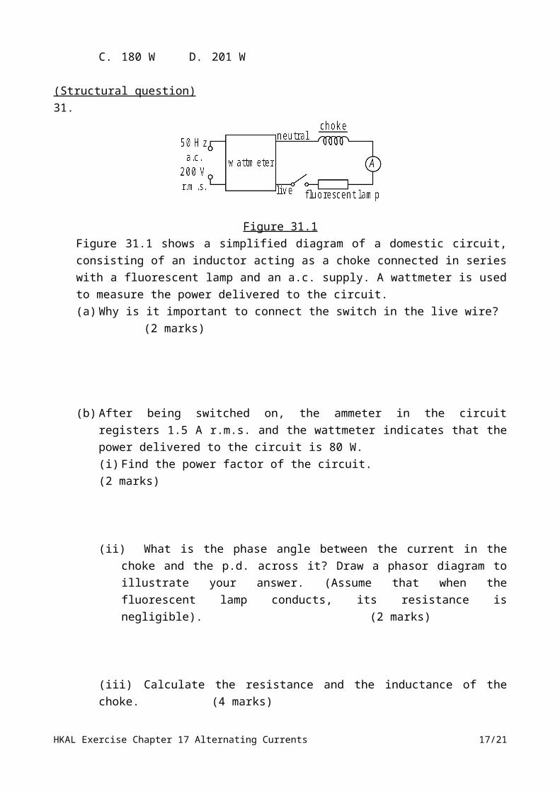
(Structural question)31.
Figure 31.1 Figure 31.1 shows a simplified diagram of a domestic circuit, consisting of an inductor acting as a choke connected in series with a fluorescent lamp and an a.c. supply. A wattmeter is used to measure the power delivered to the circuit.(a) Why is it important to connect the switch in the live wire? (2 marks)
HKAL Exercise Chapter 17 Alternating Currents 11/21

(b) After being switched on, the ammeter in the circuit registers 1.5 A r.m.s. and the wattmeter indicates that the power delivered to the circuit is 80 W.(i) Find the power factor of the circuit. (2 marks)
(ii) What is the phase angle between the current in the choke and the p.d. across it? Draw a phasor diagram to illustrate your answer. (Assume that when the fluorescent lamp conducts, its resistance is negligible). (2 marks)
(iii) Calculate the resistance and the inductance of the choke. (4 marks)
(c) The household voltage supply in Hong Kong is being changed from 200 V a.c. to 220 V a.c. Give ONE reason to support such a change. (2 marks)
32. (a) (i) What is meant by the self-inductance of a coil ? (1 mark)
(ii) A coil usually possesses resistance and inductive reactance in an a.c. circuit. Both quantities are measured in ohms (Ω). State ONE difference between them.(1 mark)
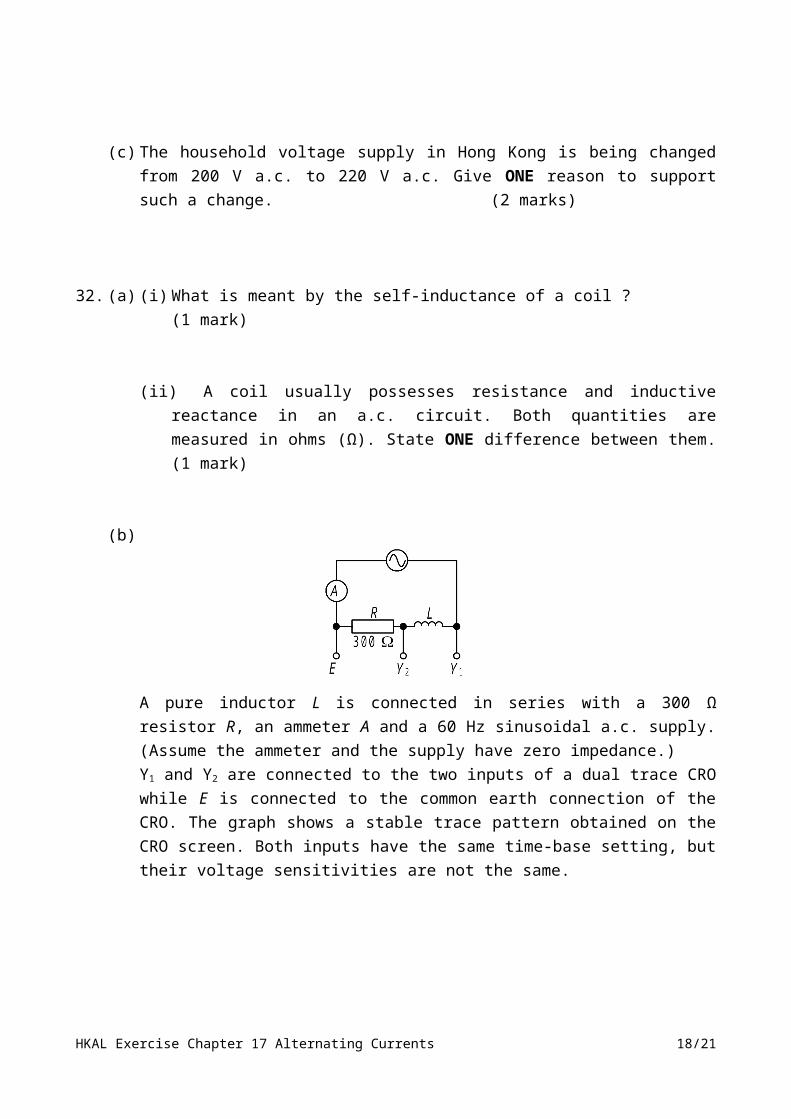
(b)
A pure inductor L is connected in series with a 300 Ω resistor R, an ammeter A and a 60 Hz sinusoidal a.c. supply. (Assume the ammeter and the supply have zero impedance.)
HKAL Exercise Chapter 17 Alternating Currents 12/21
Y1 and Y2 are connected to the two inputs of a dual trace CRO while E is connected to the common earth connection of the CRO. The graph shows a stable trace pattern obtained on the CRO screen. Both inputs have the same time-base setting, but their voltage sensitivities are not the same.
(i) What is meant by a ‘pure’ inductor ? (1 mark)
(ii) Find the phase difference (ψ) between the two traces (y1 and y2) on the screen. State which trace leads the other by phase angle ψ. (2 marks)
(iii) Deduce a value for the self-inductance of the inductor L. Show your working clearly by drawing a phasor diagram. (3 marks)
(iv) If the ammeter indicates a r.m.s. current of 40 mA, find the r.m.s. voltage of the a.c. supply. (2 marks)
HKAL Exercise Chapter 17 Alternating Currents 13/21

17.5 LRC Series Circuit Phase relation33. An alternating voltage V is applied to an
LCR series circuit, where the inductive reactance XL, the capacitive reactance XC
and the resistance R satisfy the relationXL = 4 XC = 12 R.
What is the phase difference between V and the potential difference VC across the capacitor?
A. π/3 B. 2π/3C. 5π/6 D. π
34.
In an LCR-series circuit carrying a sinusoidal alternating current, the voltages across the resistor and the inductor are 2.0 V r.m.s. and 4.5 V r.m.s. respectively. If the applied voltage is 11.0 V r.m.s. then the r.m.s. voltage across the capacitor will be
A. 4.5 V. B. 5.7 VC. 9.8 V D. 14.7 V.
35.
The root-mean-square voltages across the resistor R, capacitor C and inductor L of an RCL series circuit are respectively 2 V, 3 V and 4 V. What is the phase difference between the applied voltage and the voltage across the inductor?
A. 22∘ B. 27∘C. 63∘ D. 68∘
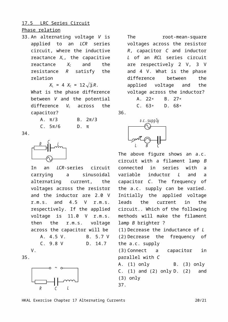
36.
The above figure shows an a.c. circuit with a filament lamp B connected in series with a variable inductor L and a capacitor C. The frequency of the a.c. supply can be varied. Initially the applied voltage leads the current in the circuit.. Which of the following methods will make the filament lamp B brighter ?(1) Decrease the inductance of L(2) Decrease the frequency of the a.c. supply(3) Connect a capacitor in parallel with CA. (1) only B. (3) onlyC. (1) and (2) only D. (2) and (3) only37.
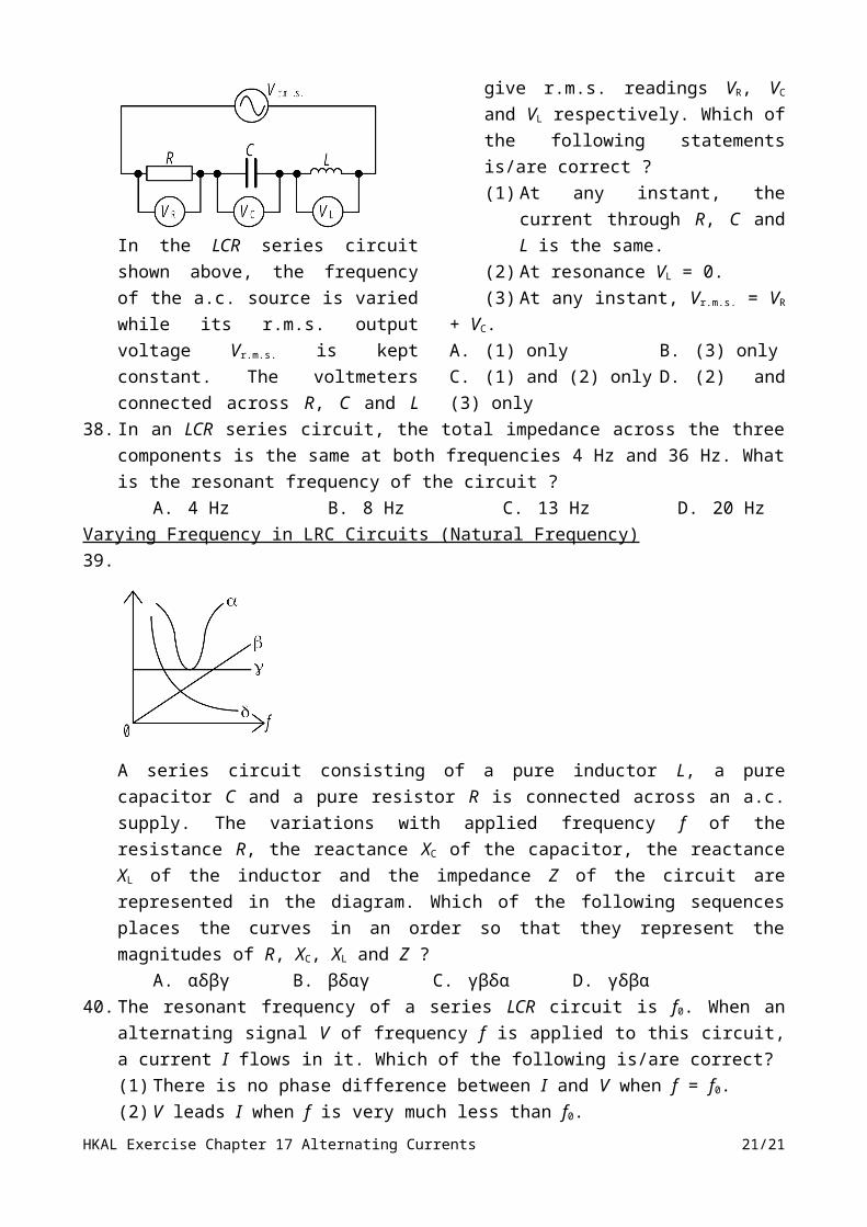
In the LCR series circuit shown above, the frequency of the a.c. source is varied while its r.m.s. output voltage Vr.m.s. is kept constant. The voltmeters connected across R, C and L give r.m.s. readings VR, VC and VL respectively. Which of the following statements is/are correct ?(1) At any instant, the current through R,
C and L is the same.(2) At resonance VL = 0.(3) At any instant, Vr.m.s. = VR + VC.
A. (1) only B. (3) onlyC. (1) and (2) only D. (2) and (3) only
HKAL Exercise Chapter 17 Alternating Currents 14/21
38. In an LCR series circuit, the total impedance across the three components is the same at both frequencies 4 Hz and 36 Hz. What is the resonant frequency of the circuit ?
A. 4 Hz B. 8 Hz C. 13 Hz D. 20 HzVarying Frequency in LRC Circuits (Natural Frequency)39.
A series circuit consisting of a pure inductor L, a pure capacitor C and a pure resistor R is connected across an a.c. supply. The variations with applied frequency f of the resistance R, the reactance XC of the capacitor, the reactance XL of the inductor and the impedance Z of the circuit are represented in the diagram. Which of the following sequences places the curves in an order so that they represent the magnitudes of R, XC, XL and Z ?
A. αδβγ B. βδαγ C. γβδα D. γδβα40. The resonant frequency of a series LCR circuit is f0. When an alternating signal V of frequency
f is applied to this circuit, a current I flows in it. Which of the following is/are correct?(1) There is no phase difference between I and V when f = f0.(2) V leads I when f is very much less than f0.(3) I leads V when f is very much greater than f0.
A. (1) only B. (3) only C. (1) and (2) only D. (2) and (3) only41. A capacitor (of negligible resistance) and a solenoid (whose resistance is not negligible) are
connected in series with an a.c. supply. The resonant frequency of the circuit can be increased by(1) replacing the solenoid with one of lower inductance, but the same resistance.(2) replacing the solenoid with one of greater resistance, but the same inductance.(3) adding a capacitor in parallel with the original capacitor.
A. (1) only B. (3) only C. (1) and (2) only D. (2) and (3) only
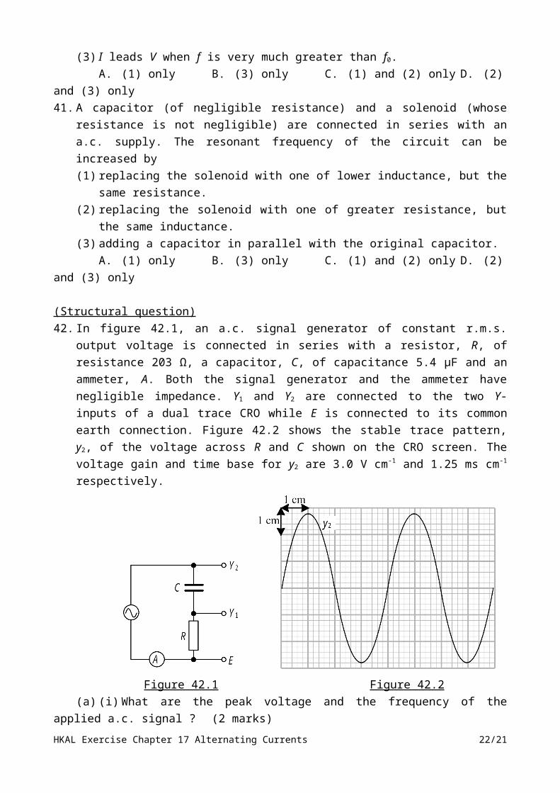
(Structural question)42. In figure 42.1, an a.c. signal generator of constant r.m.s. output voltage is connected in series
with a resistor, R, of resistance 203 Ω, a capacitor, C, of capacitance 5.4 μF and an ammeter, A. Both the signal generator and the ammeter have negligible impedance. Y1 and Y2 are connected to the two Y-inputs of a dual trace CRO while E is connected to its common earth connection. Figure 42.2 shows the stable trace pattern, y2, of the voltage across R and C shown on the CRO screen. The voltage gain and time base for y2 are 3.0 V cm-1 and 1.25 ms cm-1 respectively.
HKAL Exercise Chapter 17 Alternating Currents 15/21
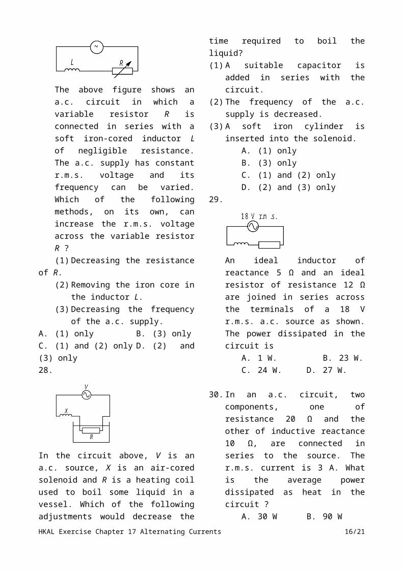
Figure 42.1 Figure 42.2(a) (i) What are the peak voltage and the frequency of the applied a.c. signal ? (2 marks)
(ii) Draw a phasor diagram to show the relationship between the applied a.c. voltage, the voltage across the capacitor and the voltage across the resistor. (2 marks)
(iii) Find the phase angle between the applied a.c. voltage and the voltage across the resistor. (2 marks)
(iv) What is the peak voltage across the resistor ? (2 marks)
(v) Sketch on Figure 42.2 the trace pattern of the voltage across R, using the same time base setting of y2 but with a voltage gain of 1 V cm-1. (2 marks)
(b) A variable inductor, L, is added to the circuit in Figure 5.1 to form an RLC series circuit. When the inductance of L is gradually increased, the reading of the ammeter A increases to a maximum and then decreases.(i) Explain why the ammeter reading attains a maximum. (2 marks)
(ii) Find the value of the inductance of L corresponding to the maximum ammeter reading. (2 marks)
HKAL Exercise Chapter 17 Alternating Currents 16/21
LC oscillator43.
A coil and a capacitor are joined in series to a signal generator as shown in the diagram. As the frequency f of the signal generator is increased, a graph of the total impedance Z of the circuit is plotted against f. If the capacitance of C is 3μF, what is the inductance of the coil ?
A. 38μHB. 1.6 mHC. 16 mHD. 15 H
44.
A capacitor C and an inductor L with some resistance are connected to a battery as shown in the figure. When switch S is moved from A to B, what is the trace observed on the screen of the CRO with the time base on ?A. B.
C. D.
45.
The figure shows an LC oscillatory circuit in which C is a capacitor and L is an air-cored inductor. At a certain instant the magnetic flux inside L is pointing upward as shown. Which of the following descriptions of the capacitor is/are possible at this instant ?(1) The capacitor is charging with the
upper plate positively charged.(2) The capacitor is charging with the
lower plate positively charged.(3) The capacitor is discharging with the
upper plate positively charged.(4) The capacitor is discharging with the
lower plate positively charged.A. (1) onlyB. (1) or (4) onlyC. (2) or (3) onlyD. (2) or (4) only
Tuning Circuit
46. A variable inductor can be used(1) as the volume control of an amplifier.(2) to tune a radio to receive a certain
channel.(3) to change the power factor of an a.c.
circuit.A. (1) onlyB. (3) onlyC. (1) and (2) onlyD. (2) and (3) only
HKAL Exercise Chapter 17 Alternating Currents 17/21
HKAL Exercise Chapter 17 Alternating Currents 18/21

HKAL Exercise (key) : Part 4 Electricity and Electromagnetism Chapter 17 Alternating Currents 1 – 10 : CCCAB, CBCAC, 11 – 20 : ABADA, DBDDC, 21 : B,22. (a) V1 = 12 0.1 V = 1.2 V 1
V2 = 5 0.1 V = 0.5 V 1V1 + V2 > 1.3 because V1 and V2 are not in phase 1 3
(b) VR amplitude correct, period correct +1
VC phase change correct, amplitude correct 1+
C phase change correct, amplitude correct 1+
2 cycles shown 5
(c) (i) increases reactance of C decreases 1 impedance of circuit decreases current increases 1 2
(ii) I = V
RC
( )22 21
1
when becomes very large, Imax = VR
= A = 1.08 A 1 2
23. (a) 1 1
HKAL Exercise Chapter 17 Alternating Currents 19/21
(b) (i) (I) VAA’ = 1
= = 0.87 V (r.m.s.) 1 2
(II) VAA’ = I & VR = IR 1
So =
C = 1
= 3.3 × 10⁻¹⁰ F
C0 = = 1.1 × 10⁻¹⁰ F m-1 1 3
(ii) (I) Zero 1 1(II) XL = ωL
At 100 kHz, XL = 2π × 100 × 103 × 10-7 = 0.06 Ω m-1 1At 1 MHz, XL = 2π × 1 × 106 × 10-7 = 0.6 Ω m-1
1 MHz is better since the order of magnitude of XL is comparable to that 1of the resistor. 2
24 – 30 : BC, DDCBB,31. (a) - The device may be at high potential when the switch is off 1
- Body touching live wire may form a low resistance to earth and current flowwould cause a shock 1 2
(b) (i) P = I V cos 80 = 1.5 200 cos 1
cos = = 0.267 1
(ii) = 74º32’ 1directions correct 1
HKAL Exercise Chapter 17 Alternating Currents 20/21
(iii) 200 cos = IR
R = 1
= 35.6 1
200 = 12
2 2 2 R L
400 400 = 35.6 35.6 + 42 50 50 L2
1 1600 = 12.67 + 42 25 L2
L = 1.27 H 1 8(c) Household appliances are mostly designed for that voltage
Using 220 V will enable such appliance to operate with increased powerOR line drop means that quite often voltage is much less than 200 V and appliancescannot work 2 2
32. (a) (i) It is the (back) e.m.f. induced in the coil per unit rate 1
of change of current in the coil (i.e. L = )
or The flux linkage through the coil per unit current passing the coil (i.e. L = ) 1 1
(ii) Resistance is frequency independent but inductive reactance depends onfrequency. 1
or Resistance dissipates power but inductive reactance does not. 1 1(b) (i) The inductor has zero resistance. 1 1
(ii) Phase difference =
ψ = (or 30∘) 1
y1 (for applied voltage) leads y2 (for current) by ψ. 1 2(iii) 2π f L = R tan 30∘ 1
L =
= 0.459 H 1
Phasor diagram 1 3(iv) Voltage of the supply,
HKAL Exercise Chapter 17 Alternating Currents 21/21
Vsupply = Isupply Z 1= (40 × 10-3) (346)= 13.8 V 1
or Vsupply cos 30∘ = Isupply R 1Vsupply = 13.8 V 1 2
33 – 40 : BDC, CACDA , 41 : A42. (a) (i) Peak voltage V = 8.4 V 1
Frequency f =
= 200 Hz 1 2(ii) 2 2
(iii) tanθ= 1
=
θ= 36∘ 1 2(iv) VR = V cosθ 1
= 8.4 cos36∘= 6.80 V 1 2
(v) 2 2
(b) (i) Peak current I = 1
When VL = VC or ωL = , current is maximum (Imax = ). 1
HKAL Exercise Chapter 17 Alternating Currents 22/21

For other values of L, the current is smaller than the maximum one. 2
(ii) ωL =
L = 1
= 0.117 H1 2
43 – 46 : AAB, D.
HKAL Exercise Chapter 17 Alternating Currents 23/21