1. damage and plasticity for concrete behavior
DESCRIPTION
Damage and Plasticity for Concrete Behavior in AbaqusTRANSCRIPT

European Congress on Computational Methods in Applied Sciences and EngineeringECCOMAS 2004
P. Neittaanmäki, T. Rossi, S. Korotov, E. Oñate, J. Périaux, and D. Knörzer (eds.)Jyväskylä, 24—28 July 2004
1
DAMAGE AND PLASTICITY FOR CONCRETE BEHAVIOR
Ludovic Jason*,o, Gilles Pijaudier-Cabot* Antonio Huerta† and Shahrokh Ghavamiano
* GeM – Institut de Recherche en Génie Civil et MécaniqueEcole Centrale de Nantes – Université de Nantes – CNRS
1, rue de la Noé – BP 92101 – F44300 Nantes, Francee-mails : [email protected], [email protected]
† Laboratori de Càlcul NumèricDepartament de Matemàtica Aplicada III
Universitat Politècnica de Catalunya, Jordi Girona 1-3 E-08034 Barcelona, Spaine-mail : [email protected]
o EDF Recherche et Développement1, avenue du Général de Gaulle
F 92141 Clamart Cedexe-mail : [email protected]
Key words: Damage, plasticity, model, concrete
Abstract. Elastic damage models or elastic plastic constitutive laws are not totally sufficientto describe the behavior of concrete. They indeed fail to reproduce the unloading slopesduring cyclic loads which define experimentally the value of the damage in the material.When coupled effects are considered, in hydromechanical problems especially, the capabilityof the numerical model to reproduce the unloading behavior is thus essential, as an accuratevalue of the damage is needed. A combined plastic – damage formulation is proposed in thiscontribution. It is applied on simple tension – compression loading to evaluate the ability ofthe law to simulate elementary situations. Two structural applications are then considered inthe form of a composite steel – concrete tube and a representative structural volume of aconfinement building for nuclear power plants.

Ludovic Jason, Gilles Pijaudier-Cabot, Antonio Huerta and Shahrokh Ghavamian
2
1 INTRODUCTION
Elastic damage models or elastic plastic laws are not totally sufficient to capture theconstitutive behavior of concrete correctly. In some cases (using damage mechanics), thecalculation of the damage variable (for isotropic cases) or tensor (anisotropic laws) is a keypoint. It can become essential when coupled effects are considered (coupling between damageand permeability, damage and porosity …). In [1], an experimental law is proposed betweenthe damage distribution in the material and its gas permeability (figure 1). Damage ismeasured using the unloading slope during cyclic compressive loading. In this case, thecapability of the constitutive model to capture the unloading behavior is thus essential if aproper evaluation of the permeability needs to be achieved.
An elastic damage model is not appropriate as irreversible strains cannot be captured: azero stress corresponds to a zero strain and the value of the damage is thus overestimated(figure 2b). An elastic plastic relation is not adapted either (even with softening, see forexample [2]) as the unloading curve follows the elastic slope (figure 2c). Another alternativeconsists in combining these two approaches to propose an elastic plastic damage law. Thesoftening behavior and the decrease of the elastic modulus are reproduced by the damage partwhile the plasticity effect accounts for the irreversible strains. With this formulation,experimental unloading can be simulated correctly (figure 2a).
Figure 1: Permeability evolution as a function of the damage value
Figure 2 : Loading – unloading behavior – Experimental and simulated behaviors
1.64
0
exp[(11.3 ) ]K
DK
=
Strain
Stress
E
(1-D) E
Strain
Stress
E
E
Strain
Stress
E
(1-D) E
Eperimental Damage model
Plastic model
a b c

Ludovic Jason, Gilles Pijaudier-Cabot, Antonio Huerta and Shahrokh Ghavamian
3
It is such a model which is presented in this contribution. First, the constitutive law isvalidated on two elementary tests. A simple tension and a cyclic compression are used toevaluate the capability of the model to simulate simple but relevant applications. Second, twostructural tests are considered in the form of a composite steel – concrete tube and a structuralrepresentative volume of a containment building for French nuclear power plants.
2 MODEL FORMULATION
Plasticity effects (irreversible strains for example) and damage (softening) are bothdecribed by the formulation. Nevertheless, they are not entirely coupled. From the total straintensor ε, an effective stress σ’ is computed from plasticity equations. Then, with the elastic –plastic strain decomposition ( e pε ε ε= + ), the damage variable D and the real stress σ arecalculated. The main advantage of this approach is to fit to numerous constitutive relations.
2.1 Plastic yield surface
In this contribution, the plastic yield surface has been chosen to fulfill three mainobjectives. First, irreversible effects have to develop during loading (achieved by definitionby every plasticity law). Then, the volumetric behavior has to be simulated correctly.Especially, the change from a contractant to a dilatant evolution during simple compressiontest has to be reproduced. This condition prevents using Von Mises equations, functions of thesecond stress invariant, that provide an elastic volumetric response. Finally, the brittle –ductile transition has to be reproduced. For high hydrostatic pressures, plastic effects appearexperimentally (see [3] for details). It supposes a closed yield surface along the first invariant(plastic threshold in confinement) and eliminates Drücker – Prager equations.
The chosen yield surface depends on the three normalized stress invariant ( , ,ρ ξ θ ) and onone hardening internal variable kh ranging from 0 to 1 (definition of a limit surface for kh = 1)[4]
3/ 2
' ' ' ' '' 1 3arcsin( )
3 2 ( ' ' )3
ij ji ij jk kiii
c ij jic
s s s s s
r s sr
σξ ρ θ= = = − (1)
with σ’ ij and s’ij the effective and deviatoric stress components respectively. rc is a parameterof the model. F is defined with three main functions k̂ (hardening function), cρ (deviatoricinvariant) and r (deviatoric shape function):
2 '2
2
ˆ( ', ) ( )( ')
( ')h ck k
Fr
ρρ= − σ σσ σσ σσ σσσσσσσσσ
(2)
The classical equations of plasticity models are solved using an iterative algorithm basedon a Newton Raphson scheme (see [5] for details).
Figure (3a) shows the evolution of the yield surface with the hardening parameter in simplecompression. Figure (3b) highlights the non symmetry of the plastic law with the Lode angle

Ludovic Jason, Gilles Pijaudier-Cabot, Antonio Huerta and Shahrokh Ghavamian
4
(in simple compression 6
πθ = , simple tension 6
πθ = − and hydrostatic confinement 0θ = ).
Finally, figure (3c) illustrates the limit surfaces for two values of θ. When the hardeningparameter kh reaches its critical level (equal to one), the yield surface becomes a failure oneand does not evolve any more.
Figure 3: Evolution of the plastic yield surface (hardening, lode angle and failure)
2.2. Damage
The damage model used in this contribution was initially developed in [6]. It describes theconstitutive behavior of concrete by introducing a scalar variable D which quantifies theinfluence of microcracking. To describe the evolution of damage, an equivalent strain εeq iscomputed from the elastic strain tensor εe
1 'e −=εεεε σσσσE (3)
with E-1 the inverse of the elastic stiffness.
32
1
( )eeq i
i
ε ε +=
= < >� (4)
where <εei>+ are the positive principal values of the elastic strains.
(a) (b)
( c )

Ludovic Jason, Gilles Pijaudier-Cabot, Antonio Huerta and Shahrokh Ghavamian
5
The damage loading surface g is defined by :
( , ) ( )e eg D d D= −= −= −= −�ε εε εε εε ε (5)
where the damage D takes the maximum value reached by d���� during the history of loading
/ ( ,0)tD Max d= ���� . d���� is computed from an evolution law that distinguishes tensile and
compressive behaviors through two couples of scalars (αt, Dt) for tension and (αc, Dc) forcompression.
( ) ( ) ( ) ( ) ( )e e et t eq c c eqd D Dα ε α ε= += += += +� ε ε εε ε εε ε εε ε ε (6)
The definition of the different parameters can be found in [6]. The damage evolutionconditions are finally given by the Kuhn – Tucker expression:
0, 0, 0g D g D≤ ≥ =� �� �� �� �
(7)
Once the damage has been computed, the “real” stress is determined using the equation :
(1 ) 'D= −σ σσ σσ σσ σ (8)
3. ELEMENTARY VALIDATION
The elastic plastic damage formulation is now going to be validated on two simple but keyapplications: tension and cyclic compression. The objective is naturally to compare thenumerical results with experiments but also with the elastic damage law for which plasticstrains are equal to zero.
3.1. Simple tension test
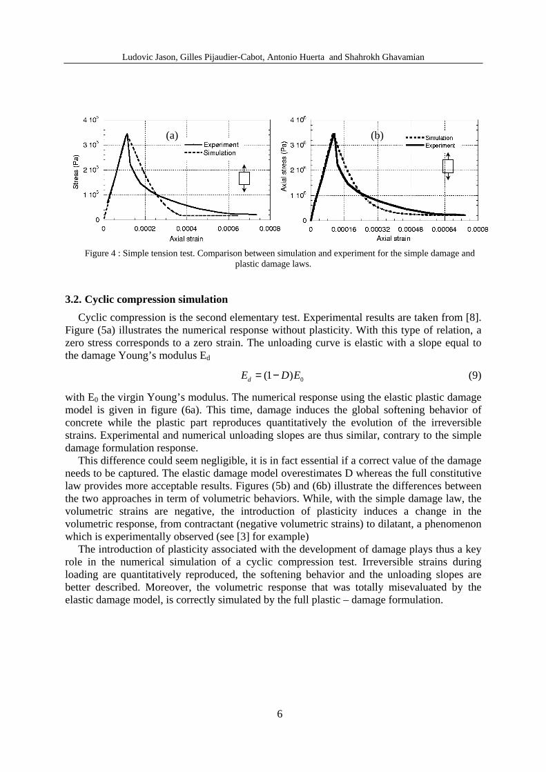
For concrete, tension is the most relevant loading that a model has to predict as far ascracking is concerned. It is indeed when concrete is subjected to tension that the first cracksusually appear. That is why the numerical response (elastic plastic damage law) is firstcompared with such a test [7]. Figure (4a) gives the axial stress – strain curve. To evaluate theinterest of including plasticity in the formulation, a pure damage model is also considered forwhich the plastic strains are supposed to keep a constant zero value so as the elastic strainsequal exactly the total strains (original damage model [6]). Figure (4b) illustrates thesimulation with the elastic damage model. As the development of damage is predominantduring simple tension tests, the two models are able to reproduce the experiment globally.Especially, the elastic plastic damage constitutive law gives a correct value of the peakposition and simulates well the post peak behavior. Choosing the appropriate parameters, themodel is thus adapted for simple tension test.
Ludovic Jason, Gilles Pijaudier-Cabot, Antonio Huerta and Shahrokh Ghavamian
6
Figure 4 : Simple tension test. Comparison between simulation and experiment for the simple damage andplastic damage laws.
3.2. Cyclic compression simulation
Cyclic compression is the second elementary test. Experimental results are taken from [8].Figure (5a) illustrates the numerical response without plasticity. With this type of relation, azero stress corresponds to a zero strain. The unloading curve is elastic with a slope equal tothe damage Young’s modulus Ed
0(1 )dE D E= − (9)
with E0 the virgin Young’s modulus. The numerical response using the elastic plastic damagemodel is given in figure (6a). This time, damage induces the global softening behavior ofconcrete while the plastic part reproduces quantitatively the evolution of the irreversiblestrains. Experimental and numerical unloading slopes are thus similar, contrary to the simpledamage formulation response.
This difference could seem negligible, it is in fact essential if a correct value of the damageneeds to be captured. The elastic damage model overestimates D whereas the full constitutivelaw provides more acceptable results. Figures (5b) and (6b) illustrate the differences betweenthe two approaches in term of volumetric behaviors. While, with the simple damage law, thevolumetric strains are negative, the introduction of plasticity induces a change in thevolumetric response, from contractant (negative volumetric strains) to dilatant, a phenomenonwhich is experimentally observed (see [3] for example)
The introduction of plasticity associated with the development of damage plays thus a keyrole in the numerical simulation of a cyclic compression test. Irreversible strains duringloading are quantitatively reproduced, the softening behavior and the unloading slopes arebetter described. Moreover, the volumetric response that was totally misevaluated by theelastic damage model, is correctly simulated by the full plastic – damage formulation.
(a).
(b).

Ludovic Jason, Gilles Pijaudier-Cabot, Antonio Huerta and Shahrokh Ghavamian
7
Figure 5: Cyclic compression test for the elastic damage law. Axial (a) and volumetric (b) responses
Figure 6: Cyclic compression test for the elastic plastic damage model. Axial (a) and volumetric (b) responses
4. STRUCTURAL APPLICATIONS
4.1. Circular concrete filled steel tube (passive confinement)
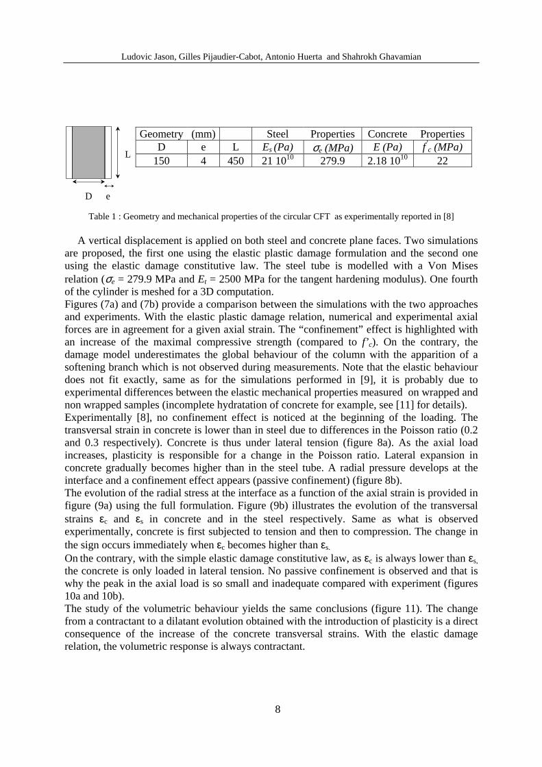
To highlight the interest of the presented constitutive law, the behaviour of a circularconcrete filled steel tube (CFT) is going to be simulated. The dimensions and geometry of thesample and the mechanical properties experimentally reported in [9], measured on nonwrapped specimens, are listed in table 1.
The steel – concrete interface is assumed to be perfect. For the considered compressivestrength f’ c, Giakoumelis and Lam [10] demonstrate with greased and non greased cylinders,that the steel-concrete interface has little influence on the global behaviour.
(a).
(b).
(a) (b)
Ludovic Jason, Gilles Pijaudier-Cabot, Antonio Huerta and Shahrokh Ghavamian
8
Geometry (mm) Steel Properties Concrete PropertiesD e L Es (Pa) σe (MPa) E (Pa) f’ c (MPa)
150 4 450 21 1010 279.9 2.18 1010 22
Table 1 : Geometry and mechanical properties of the circular CFT as experimentally reported in [8]
A vertical displacement is applied on both steel and concrete plane faces. Two simulationsare proposed, the first one using the elastic plastic damage formulation and the second oneusing the elastic damage constitutive law. The steel tube is modelled with a Von Misesrelation (σe = 279.9 MPa and Et = 2500 MPa for the tangent hardening modulus). One fourthof the cylinder is meshed for a 3D computation.Figures (7a) and (7b) provide a comparison between the simulations with the two approachesand experiments. With the elastic plastic damage relation, numerical and experimental axialforces are in agreement for a given axial strain. The “confinement” effect is highlighted withan increase of the maximal compressive strength (compared to f’ c). On the contrary, thedamage model underestimates the global behaviour of the column with the apparition of asoftening branch which is not observed during measurements. Note that the elastic behaviourdoes not fit exactly, same as for the simulations performed in [9], it is probably due toexperimental differences between the elastic mechanical properties measured on wrapped andnon wrapped samples (incomplete hydratation of concrete for example, see [11] for details).Experimentally [8], no confinement effect is noticed at the beginning of the loading. Thetransversal strain in concrete is lower than in steel due to differences in the Poisson ratio (0.2and 0.3 respectively). Concrete is thus under lateral tension (figure 8a). As the axial loadincreases, plasticity is responsible for a change in the Poisson ratio. Lateral expansion inconcrete gradually becomes higher than in the steel tube. A radial pressure develops at theinterface and a confinement effect appears (passive confinement) (figure 8b).The evolution of the radial stress at the interface as a function of the axial strain is provided infigure (9a) using the full formulation. Figure (9b) illustrates the evolution of the transversalstrains εc and εs in concrete and in the steel respectively. Same as what is observedexperimentally, concrete is first subjected to tension and then to compression. The change inthe sign occurs immediately when εc becomes higher than εs.
On the contrary, with the simple elastic damage constitutive law, as εc is always lower than εs,
the concrete is only loaded in lateral tension. No passive confinement is observed and that iswhy the peak in the axial load is so small and inadequate compared with experiment (figures10a and 10b).The study of the volumetric behaviour yields the same conclusions (figure 11). The changefrom a contractant to a dilatant evolution obtained with the introduction of plasticity is a directconsequence of the increase of the concrete transversal strains. With the elastic damagerelation, the volumetric response is always contractant.
D e
L

Ludovic Jason, Gilles Pijaudier-Cabot, Antonio Huerta and Shahrokh Ghavamian
9
As a conclusion, the elastic plastic damage constitutive law is necessary to achieve the changeof Poisson ratio that accounts for the passive confinement. For concrete filled steel tubessubjected to axial compressive loading, it is possible to reproduce experimental resultscorrectly and especially the evolution of the axial capacity.
Figure 7 : Simulation of a CFT(a) Evolution of the axial force as a function of the axial strain. Comparison between the elastic plastic damage
formulation and the experiment; (b) Comparison between the elastic plastic damage and the elastic damagemodels
Figure 8 : Evolution of the radial “pressure” ( σr ) as a function of the steel ( εs ) and concrete ( εc ) transversalstrains.
a.
b.
c sε ε<
rσ
c sε ε>
rσ
(a).
(a) (b)
concrete steel

Ludovic Jason, Gilles Pijaudier-Cabot, Antonio Huerta and Shahrokh Ghavamian
10
Figure 9 : Transversal behaviour using the elastic plastic damage model(a) Evolution of the concrete transversal stress as a function of the axial strain; (b) Evolution of the transversalconcrete and steel transversal strains as a function of the axial strain; (c) Zoom on the first part of the curve.
Figure 10 : Transversal behaviour using the elastic damage model(a) Evolution of the transversal stress as a function of the axial strain, (b) evolution of the concrete and strain
transversal strains as function of the axial strain
Figure 11 : Evolution of the volumetric strain as a function of the axial force for both approaches.
(a).
(b).
(c).
(b).

Ludovic Jason, Gilles Pijaudier-Cabot, Antonio Huerta and Shahrokh Ghavamian
11
4.2. Representative Structural Volume of a containment building
The application presented in this part has been proposed by Electricité de France. The test,named PACE 1300, is a Representative Structural Volume (RSV) of a prestressed pressurecontainment vessel (PPCV) of a French 1300 MWe nuclear power plant. Figure 12 illustratesthe location of the RSV within the entire PPCV structure. The model incorporates almost allcomponents of the real structure: concrete, vertical and horizontal reinforcement bars,transversal reinforcements, and prestressed tendons in both horizontal and vertical directions.The size of the RSV is chosen to respect 3 conditions: large enough to include a sufficientnumber of components (specially prestress tendons) and to offer a significant observation areain the centre, far enough from boundary conditions, while remaining as small as possible toease computations. The model was prepared using Gibiane [12] mesh generating scriptswhich create models with different mesh refinements. This was an important aspect of thisapplication, where the mesh size effect was of great concern on various nonlinearcalculations.
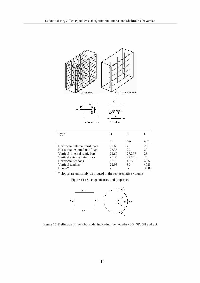
The RSV includes 11 horizontal and 10 vertical reinforcement bars (on both internal andexternal faces), 5 horizontal and 3 vertical prestressed tendons, and 24 reinforcement hoopsuniformly distributed in the volume. The geometry of the problem is given in figure 13.Figure 14 provides information about the steel distribution and properties.
Figure 12. Position of the extracted Representative Structural Volume (RSV).
Figure 13. Geometry of the Representative Structural Volume (RSV)
Ludovic Jason, Gilles Pijaudier-Cabot, Antonio Huerta and Shahrokh Ghavamian
12
Type R e D
m cm mm
Horizontal internal reinf. bars 22.60 20 20Horizontal external reinf.bars 23.35 20 20Vertical internal reinf. bars 22.60 27.297 25Vertical external reinf. bars 23.35 27.170 25Horizontal tendons 23.15 40.5 40.5Vertical tendons 22.95 80 40.5Hoops* x x 3.685
* Hoops are uniformly distributed in the representative volume
Figure 14 : Steel geometries and properties
Figure 15: Definition of the F.E. model indicating the boundary SG, SD, SH and SB

Ludovic Jason, Gilles Pijaudier-Cabot, Antonio Huerta and Shahrokh Ghavamian
13
Figure 16. Boundary conditions and loading for the Representative Volume
The behaviour of the RSV needs to be as close as possible to the in situ situation. Thefollowing boundary conditions have been chosen : face SB blocked along OZ, on face SH allnodes are restrained to follow the same displacement along OZ and no rotations are allowedfor faces SG and SD (see Figures 15 and 16). A more adequate boundary condition wouldhave probably been a periodic one on SG and SD.
In order to model the effect of prestressed tendons, bar elements were anchored to facesSG and SD for horizontal cables and to faces SB and SH for vertical tendons, then prestressedusing internal forces. Then, these elements are restrained to surrounding concrete elements torepresent the prestressing technology applied in French PPCVs. The integrity test loading isrepresented by a radial pressure on the internal face SI and the bottom effect applied on faceSH (tensile pressure proportional to the internal pressure to simulate the effect of theneighbouring structure). The body weight of RSV and that of the surrounding upper-structureare also taken into account. With these conditions, a mesh containing 16,500 Hexa20elements for concrete and 1200 bar elements for reinforcement and tendons is used in thepresented computation.
Figure 17 provides the internal pressure applied on the volume as a function of thedisplacement of a point located at the bottom right of the internal face, using the elastic plasticdamage formulation. This curve can be divided in four parts. The initial state corresponds tothe application of the prestress on the tendons. This yields a compaction of the volume and
z
θND ND
VD
g PSHPSH
PSV
PSV
WE BE
IP z
r
Boundary conditions indisplacement
ND : zero normal displacementon SG and SD
NV : zero vertical relation onSB
RO : zero rotation on SH
RO
Boundary conditions in stressPSH : horizontal prestress
5.28 MN per tendonPSV : vertical prestress
6.93 MN per tendonWE : weight of the
surrounding structure1.61 MPag : gravity
LoadingIP : internal pressureBE : tensile pressure
proportional to the internalpressure (bottom effect)

Ludovic Jason, Gilles Pijaudier-Cabot, Antonio Huerta and Shahrokh Ghavamian
14
due to the boundary conditions (no normal displacement on the lateral face), it imposes aninitial negative radial displacement (see figure 18). Then, upon application of the internalpressure, there is a zone of linear behaviour where the compaction is reduced and the structurereturns towards its initial rest position before undergoing tension for higher values of internalpressure. Damage does not evolve during state 2. The development of damage occurs duringstate 3. Finally, a partial unloading of the volume occurs (state 4) due to heavy cracking of thestructure.
Figure 17: Displacement – Pressure curve for the representative structural volume
Figure 18: Radial deflection of the RSV through different steps (schematic). View from the top of the volume
Figure 19 describes the distribution of the damage variable in the volume for two differentloading steps (just after the apparition of non linearity and after the peak). Damage initiallydevelops along the vertical tendon which is located in the middle of the mesh. Then, itpropagates in the depth of the volume and along the vertical axis. It finally forms a localized
Step « zero »
Step 1 : Initial state after theapplication of the prestress
Step 2 : Application of theinternal pressure
State 1
State 2
State 3
State 4

Ludovic Jason, Gilles Pijaudier-Cabot, Antonio Huerta and Shahrokh Ghavamian
15
damaged zone in the middle of the structure. Similar results can be found in [13] with theelastic damage model (without plasticity). It tends to prove that for this tension dominantapplication, the introduction of plasticity does not disturb the development of damage.However, it is the amount of damage at a given loading state which is different according tothe damage and plastic damage models. In the second one, damage is lower than in the firstone and effects on the material permeability are drastically different (see figure 1). It followsthat evaluation of leakage according to these two models are expected to be very different too.
Figure 19 : Damage distribution in the representative structural volume. Initiation of the damage andlocalized band. The blacker the zone is, the larger the damage is.
5. CONCLUSION
An elastic plastic damage formulation has been proposed and tested on both tension andcompression applications. It has been shown that the constitutive law proposes the sameadvantages as the elastic damage model for tension dominant cases but also improves theconstitutive response when compression is considered.
For simple tension test, the law is able to simulate both peak and post – peak (especiallysoftening) behaviors. The choice for the plastic yield surface enables to reproducequalitatively and quantitatively the axial and volumetric responses of a concrete cylinderloaded in compression. Particularly, the development of irreversible strains and the changefrom a contractant to a dilatant volumetric evolution are correctly simulated.
For structural applications, the improvements are also highlighted. Including plasticity isthe most appropriate solution to achieve the passive confinement effect of a concrete filledsteel tube (increase in the Poisson ratio). Finally, for the representative structural volume, thedevelopment of damage is correctly described, following the same path as previouslymentioned in former studies.
As a conclusion, this constitutive law may represent an appropriate tool to simulate theexperimental damage value and may be used for coupled problems (hydro mechanicalsimulations) for example.

Ludovic Jason, Gilles Pijaudier-Cabot, Antonio Huerta and Shahrokh Ghavamian
16
6. AKNOWLEDGMENTS
Partial financial support from EDF and from the EU through MAECENAS project (FIS5-2001-00100) is gratefully acknowledged. The authors particularly thank R. Crouch(University of Sheffield) for his help in the design and the numerical development of theplasticity model. The authors would like to thank EDF for scientific support toward thedevelopments in the FE code “Code_Aster”.
7. REFERENCES
[1] V. Picandet, A. Khelidj, G. Bastian, Effect of axial compressive damage on gaspermeability of ordinary and high performance concrete, Cement and Concrete Research,31, 1525-1532, 2001
[2] P. Grassl, K. Lundgren, K. Gylltoft, Concrete in compression: a plasticity theory with anovel hardening law, International Journal of Solids and Structures,80, 5205-5223, 2002
[3] D. Sfer, I. Carol, R. Gettu, G. Etse, Study of the behavior of concrete under triaxialcompression, Journal of Engineering Mechanics, 128, 156-163, 2002
[4] G. Etse, K.J. Willam, Fracture energy formulation for inelastic behaviour of crackingconcrete, ASCE Journal of Engineering Mechanics, 106, 1013-1203, 1994
[5] A. Perez-Foguet, A. Rodriguez-Ferran, A. Huerta, Numerical differentiation for non trivialconsistent tangent matrices: an application to the MRS – Lade model, InternationalJournal for Numerical Methods in Enginnering, 48, 159-184, 2000
[6] J. Mazars, Application de la mécanique de l’endommagement au comportement nonlinéaire et à la rupture du béton de structure, PhD Thesis, université Paris VI, 1984.
[7] V.S Gopalaratnam, S.P. Shah, Softening response of plain concrete in direct tension, ACIJournal, 310-323, 1985
[8] B.P. sinha, K.H. Gerstle, L.G. Tulin, Stress strain relations for concrete under cyclicloading, Journal of the American Concrete Institute, 195-211, 1964.
[9] K.A.S. Susantha, H. Ge, T. Usami, Uniaxial stress strain relationship of concrete confinedby various shaped steel tubes, Engineering Structures, 23, 1331-1347, 2001
[10] G. Giakoumelis, D. Lam, Axial capacity of circular concrete filled tube columns, Journalof Constructational Steel Research, in press, 2004
[11] M. Kwon, E. Spacone, E., Three – dimensional finite element analyses of reinforcedconcrete columns, Computers and Structures 80, 199-212, 2002.
[12] Castem, Castem 2000, User’s guide, CEA, DMT, LAMS, 1993
[13] L. Jason, S. Ghavamian, G. Pijaudier-Cabot, A. Huerta, Benchmarks for the validation ofa non local damage model, Revue Française de Génie Civil, in press