2. chapter 2
DESCRIPTION
pmfmTRANSCRIPT

BITS PilaniK K Birla Goa Campus
ME F341Prime Movers and Fluid Machines
Dr. Sandesh S. ChouguleDepartment of Mechanical Engineering

BITS Pilani, K K Birla Goa Campus
Hydraulics Turbines
BITS Pilani, K K Birla Goa Campus
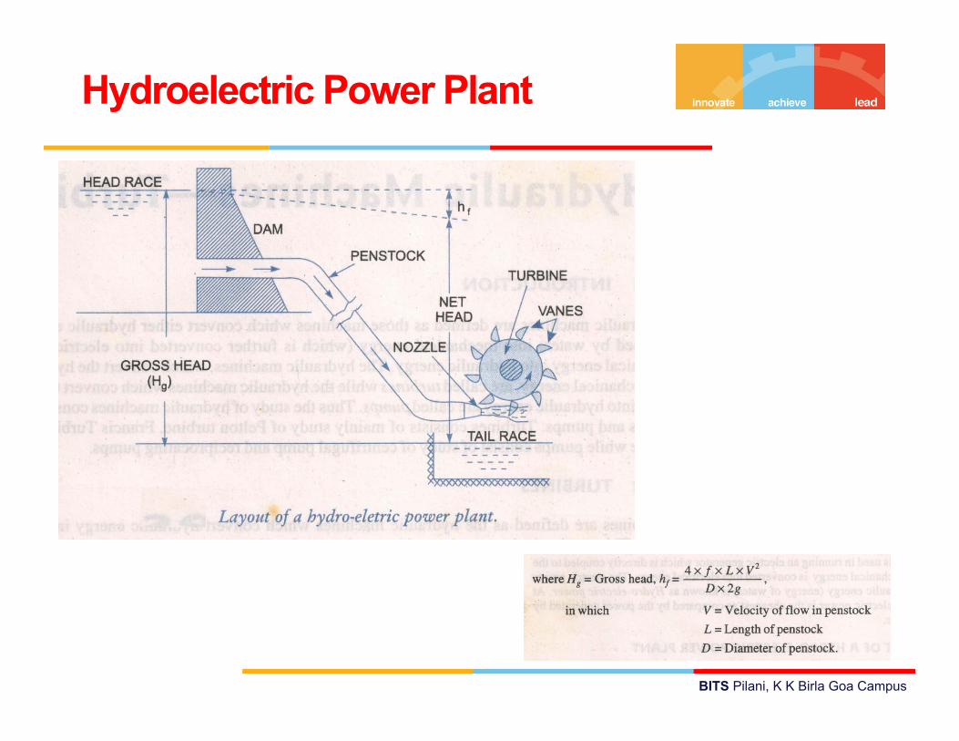
Hydroelectric Power Plant

BITS Pilani, K K Birla Goa Campus
Hydraulic efficiency
Efficiencies of a Turbine

BITS Pilani, K K Birla Goa Campus
Mechanical efficiency
Volumetric efficiency

BITS Pilani, K K Birla Goa Campus
Overall efficiency
BITS Pilani, K K Birla Goa Campus
According to action of flow
Impulse turbines Reaction Turbines
According to direction of flow
Tangential flow Radial flow Axial flow Mixed flow
Classifications of Hydraulic Turbines

BITS Pilani, K K Birla Goa Campus
According to Head and Quantity of water
High head (150 m to 2000 m) Medium head (30 m to 150 m) Low head (< 30 m)
According to Specific speed
Low specific speed (10 to 50) Medium specific speed (50 to 250) High specific speed (> 250)

BITS Pilani, K K Birla Goa Campus
• In an impulse turbine, all the available energy of water isconverted into kinetic energy or velocity head by passing itthrough a contracting nozzle provided at the end ofpenstock.
• The runner revolves freely in air.• The water is in contact with only a part of the runner at a
time and throughout its action on the runner and itssubsequent flow to the tailrace, the water is at atmosphericpressure.
• Eg. Pelton wheel, Girard turbine, Banki turbine, Jonval,Turgo-impulse wheel etc…
Impulse and Reaction Turbines

BITS Pilani, K K Birla Goa Campus
• In reaction turbine, at entrance of the runner, only part ofthe available energy of water is converted into kineticenergy and substantial part remains in the form of pressureenergy.
• As water flows through the runner the change frompressure to kinetic energy takes place gradually.
• As such the pressure at the inlet of turbine is much higherthan the pressure at outlet and it varies throughout thepassage of water through turbine.
• The difference of pressure between the inlet and the outletof runner is called reaction pressure and these turbine isknown as reaction turbines.
• Eg. Thomson, Francis, Propeller, Kaplan, Fourneyron etc.

BITS Pilani, K K Birla Goa Campus
BITS Pilani, K K Birla Goa Campus
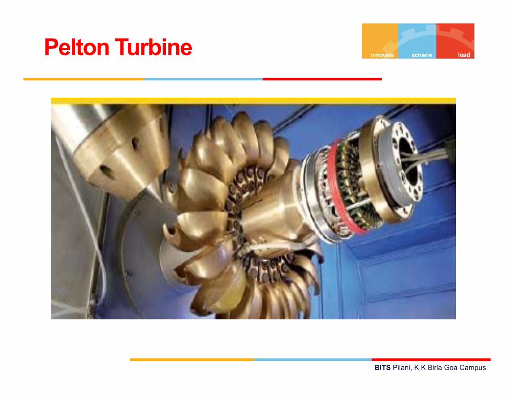
Pelton Turbine

BITS Pilani, K K Birla Goa Campus
Introduction
• Named after the designer Mr. A. Pelton in California at
1810
• Impulse turbine- as there is no pressure drop across the
buckets
• Suitable for high heads of about 100-500m
• Requires comparatively less quantity of water

BITS Pilani, K K Birla Goa Campus
Schematic Diagram

BITS Pilani, K K Birla Goa Campus
Working
• Water supplied is from a high head through a longconduit called penstock.
• The water is accelerated in nozzle and the head isconverted into velocity and discharges at high speed inthe form of a jet at atmospheric pressure
• The jet strikes buckets attached to the rim of a rotatingwheel (runner)
• Impact of water on buckets produce a force whichcauses the wheel to rotate by supplying a torque on theshaft
• water discharged at relatively low speed falls into lowerreservoir or tail race

BITS Pilani, K K Birla Goa Campus
Nozzle Assembly

BITS Pilani, K K Birla Goa Campus
• Power produced by turbine proportional to QxHwhere Q : Volume flow rate
H : effective head• Since H cannot be varied easily, Q (cross sectional area x
velocity of flow is varied)• For wheel speed to be maintained constant, jet velocity is
not varied.• Cross sectional area is varied using a spear valve• Spear valve is actuated to and fro as per the power
demand

BITS Pilani, K K Birla Goa Campus
Deflector
• Sometimes, need arises for immediate closure of nozzle.
• If flow is reduced suddenly, high back pressure waves
will be generated on penstock pipes
• Deflector alters the jet trajectory

Runner with Buckets
Undercuts are provided so that the jet bye-passes the inclined blades which are obstructing the jet to strike the blade which is vertical in position

BITS Pilani, K K Birla Goa Campus
• Usually more than 15 buckets• Each bucket is split vertically into two parts by a splitter
that has a sharp edge at the center• Striking jet of water is divided into two parts by the splitter• each part of jet flows sideways round the smooth inner
surface of the bucket and leaves it with a relative velocityalmost opposite in direction of the original jet
• Notch at the edge of outer rim of each bucket ensures aloss free entry of the jet into the buckets.
Bucket of pelton turbine
BITS Pilani, K K Birla Goa Campus
• Maximum change in momentum is obtained when the jet is180°
• But angle is restricted to 165° so that the fluid leaving onebucket does not strike back the succeeding bucket
• Buckets are made of special bronze- steel alloys withNickel, Chromium or stainless steel.
• Buckets are properly polished for smooth change indirection and the formation of low pressure pockets causeddue to erosion are avoided
• Buckets can be bolted construction( for large turbines) orof single cast

BITS Pilani, K K Birla Goa Campus
• Prevents splashing of water
• Guides water to flow through the tail race
• Provides housing and support to the thrust bearings and
shaft
• Since the buckets are symmetrical, side or axial thrusts
produced by water in each half is balanced
• Provides safety against accidents
Casing

BITS Pilani, K K Birla Goa Campus
Indian Scenario

BITS Pilani, K K Birla Goa Campus
Analysis of Pelton Wheel Turbine

BITS Pilani, K K Birla Goa Campus
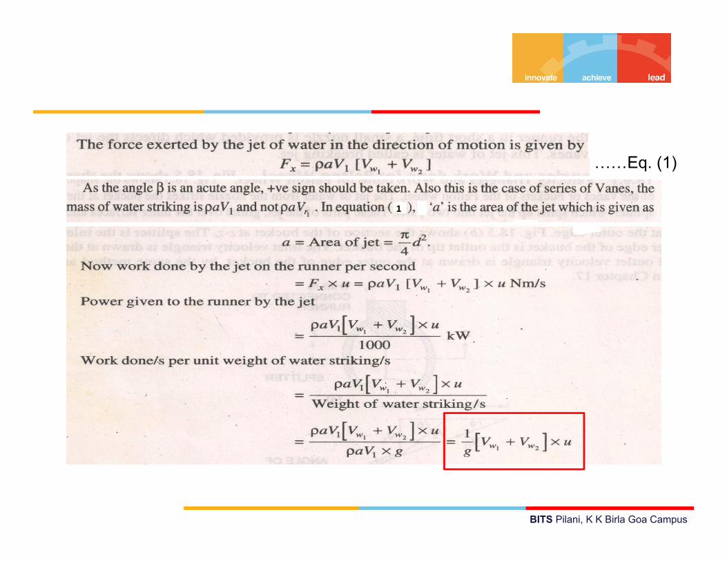
Work done by Pelton Wheel

BITS Pilani, K K Birla Goa Campus
BITS Pilani, K K Birla Goa Campus
……Eq. (1)

BITS Pilani, K K Birla Goa Campus
………….Eq. 2
…….Eq. 3
BITS Pilani, K K Birla Goa Campus
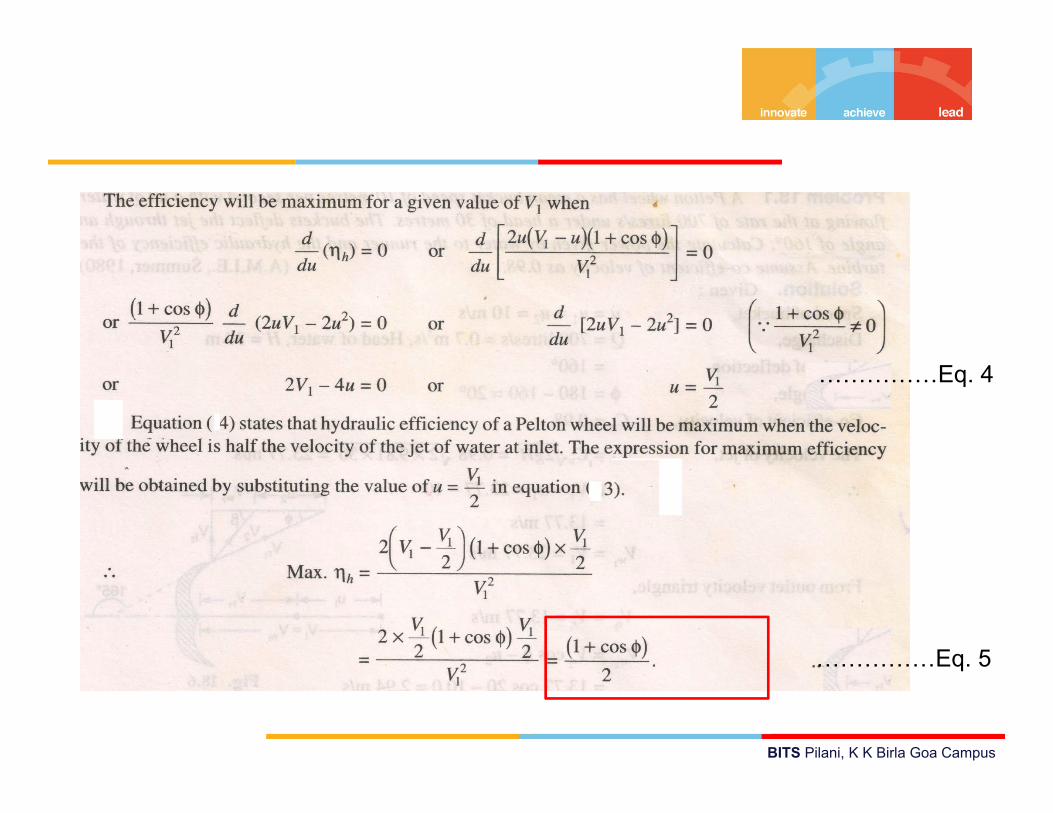
……………Eq. 5
……………Eq. 4
BITS Pilani, K K Birla Goa Campus
BITS Pilani, K K Birla Goa Campus
Problem 1:
Two jet strike the buckets of a pelton wheel, which is
having shaft power as 15450 kW. The diameter of each jet
is given as 200 mm. If the net head on the turbine is 400
m. Find overall efficiency of the turbine. Take Kv = 1.0

BITS Pilani, K K Birla Goa Campus

BITS Pilani, K K Birla Goa Campus
BITS Pilani, K K Birla Goa Campus
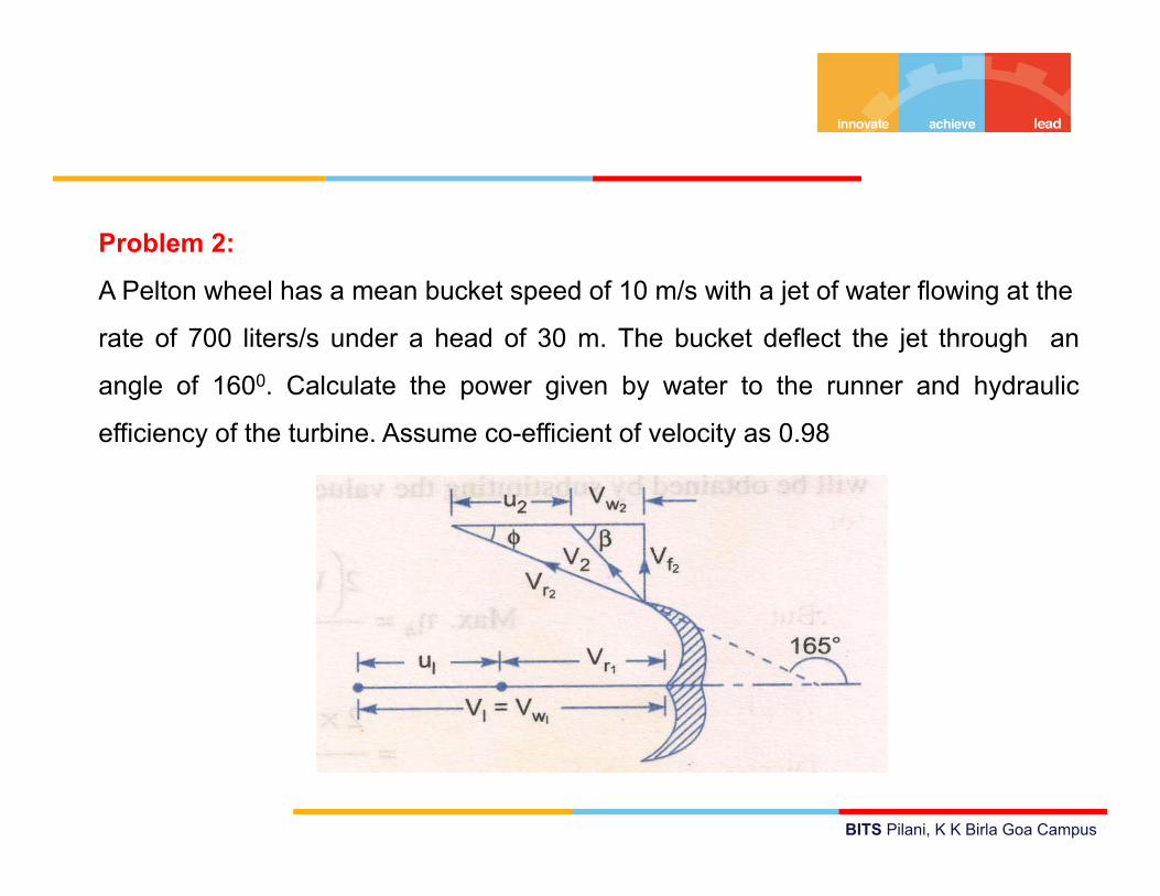
Problem 2:
A Pelton wheel has a mean bucket speed of 10 m/s with a jet of water flowing at the
rate of 700 liters/s under a head of 30 m. The bucket deflect the jet through an
angle of 1600. Calculate the power given by water to the runner and hydraulic
efficiency of the turbine. Assume co-efficient of velocity as 0.98

BITS Pilani, K K Birla Goa Campus

BITS Pilani, K K Birla Goa Campus

BITS Pilani, K K Birla Goa Campus
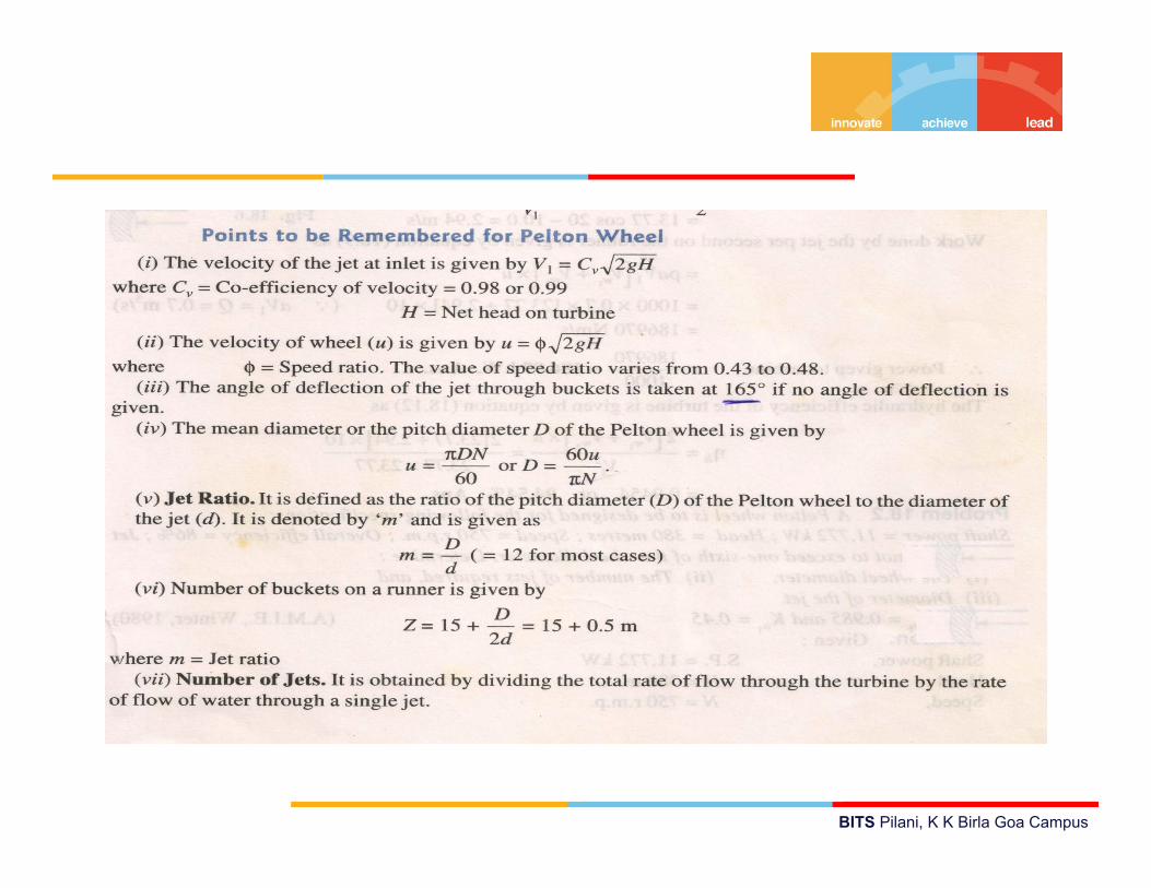
Design of Pelton Wheel Turbine

BITS Pilani, K K Birla Goa Campus
Design of Pelton wheel means the following data is to be
determined :
Diameter of the jet (d)
Diameter of wheel (D)
Width of the buckets which is = 5 × d
Depth of the buckets which is = 1.2 × d
Number of buckets on the wheel

BITS Pilani, K K Birla Goa Campus
Problem 1
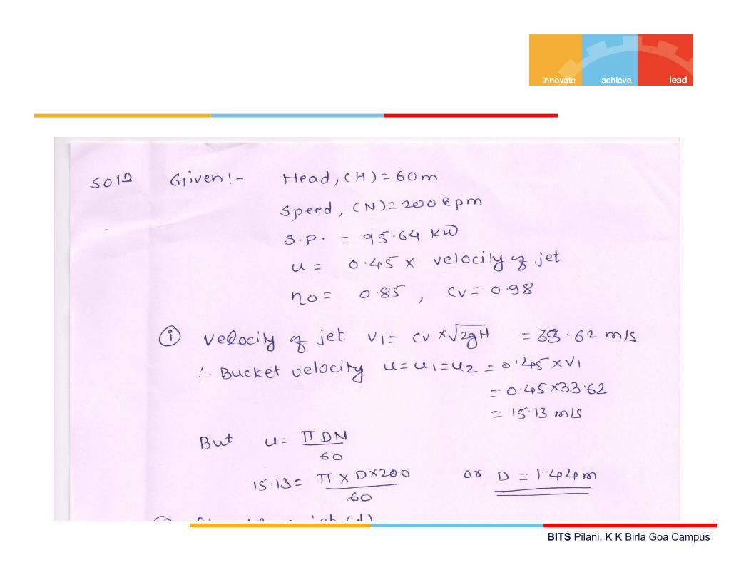
A Pelton wheel is to be designed for a head of 60m when
running at 200 rpm. The Pelton wheel develops 95.64 kW
shaft power. The velocity of the buckets = 0.45 times the
velocity of the jet, overall efficiency = 0.85 and co-efficient
of the velocity is equal to 0.98
BITS Pilani, K K Birla Goa Campus

BITS Pilani, K K Birla Goa Campus

BITS Pilani, K K Birla Goa Campus
Problem 2The three jet Pelton turbine is required to generate 10,000kW under net head of 400 m. The blade angle at outlet is 150
and reduction in the relative while passing over the blade is5%. If the overall efficiency of the wheel is 80%, Kv = 0.98and speed ratio = 0.46, then find: (i) the diameter of the jet,(ii) Total flow in m3/s and (iii) force exerted by a jet on thebuckets. If the ratio of jet not to be less than 10, find thespeed of the wheel for frequency of 50 Hz/sec and thecorresponding wheel diameter.[Ans. (i) 125mm, (ii) 3.18 m3/s, (iii) 94.05 kN, (iv) 600 rpm]

BITS Pilani, K K Birla Goa Campus
Problem 3:
A Pelton wheel turbine is to be designed for following specifications:
Shaft power = 11,772 kW;
Head = 380 m;
Speed = 750 rpm;
Overall efficiency = 86%.
Jet diameter is not to exceed one-sixth of the wheel diameter.
Determine:
(i) The wheel diameter [Ans. 0.989 m]
(ii) The number of jets required [Ans. 2]
(iii) Diameter of jet [Ans. 0.165m]
Take Kv1= 0.984 and Ku1=0.45

BITS Pilani, K K Birla Goa Campus
Problem 4The following data is related to a Pelton wheel turbine:Head at base of the nozzle = 80 mDiameter of jet = 100 mDischarge of the nozzle = 0.30 m3/sPower at the shaft = 206 kWPower absorbed in Mechanical resistance = 4.5 kWDetermine (i) Power lost in nozzle [Ans. 16.59 kW ],
(ii) Power lost due to hydraulic resistance inthe runner. [Ans. 8.35 kW ]
BITS Pilani, K K Birla Goa Campus
Problem 5:
A Pelton wheel nozzle, for which Cv= 0.97, is 400 m below
the water surface of a lake. The jet diameter is 0.6 m, its
length is 4 km and f = 0.0032. The buckets , deflect the jet
throgh 1650 and they run at 0.48 times jet speed, bucket
friction reducing the relative velocity at outlet by 15% of
relative velocity at inlet . Mechanical efficiency = 90%. Find
the flow rate and shaft power developed by the turbine.
[Ans. Q = 0.419 m3/s, SP = 1194 kW ]

BITS Pilani, K K Birla Goa Campus
Problem 6
Determine the power given by the jet of water to the runner
of a pelton wheel which is having tangential velocity a 20
m/s. The net head on the turbine is 50 m and discharge
through the jet water is 0.03 m3/s. The side clearance
angle 150 and take Kv= 0.975.
[Ans. 12.43 kW ]