greenpresent.tistory.comgreenpresent.tistory.com/attachment/cfile22.uf@274c3b... · web viewdigital...
TRANSCRIPT

Digital communication
Introduction
인터넷 공학부( 충남대학교 홈에서 발췌 )
1

통 신
o 위성 통신
o BISDN(Broadband Integrated Services Digital Network)
- 전화기, TV, 컴퓨터등 가전기기 기능 다양화
원격 감시, 원격 검침, 원격 조정
- 영상, 고속 데이터
o 회사/업무통신
- 컴퓨터 통신
- Video Conference- Electronic Banking- Cellular/PCS
- 팩스
o Entertainment
o 원격 진료
o 교육
o 국방
o 민간 항공
신호의 형태
2

1. 아날로그 신호
일정 구간내의 모든 시간에 함수값이 정의됨
2. 샘플링된 신호
특정한 시점에만 함수값이 정의됨.
3. 디지털 신호
특정한 시점에만 한정된 수치 중 하나로 함수값이 정의됨
3

디지털 통신의 장점
1. 발전하는 디지털 신호처리 기술을 활용가능
2. 디지털소자가 아날로그보다 저렴하고 신뢰성이 높음
3. Coding 기술을 활용하여 잡음 또는 간섭신호 영향
최소화. 예 : 오류정정코드
4. 신호의 다중화, Interleaving 등이 용이함
5. 디지털 신호는 전송로의 Nonlinearity 에 의한 Distor -tion
에 강함
6. Regenerative Repeater 사용가능
7. 정보비화 및 전송로 비화가 용이
8. 컴퓨터 활용 용이(입출력 신호가 디지털)
9. 광통신 및 위성통신 링크가 디지털 통신방식이 적합
COST
1. 디지털 방식으로 전송 시 필요한 대역폭이 일반적으로
아나로그 방식보다 넓은 주파수 대역폭 필요
2. 송수신기 동기(synchronization) 필요
4
EncryptorSourceEncoder
ChannelEncoder f(t)Signal
Source
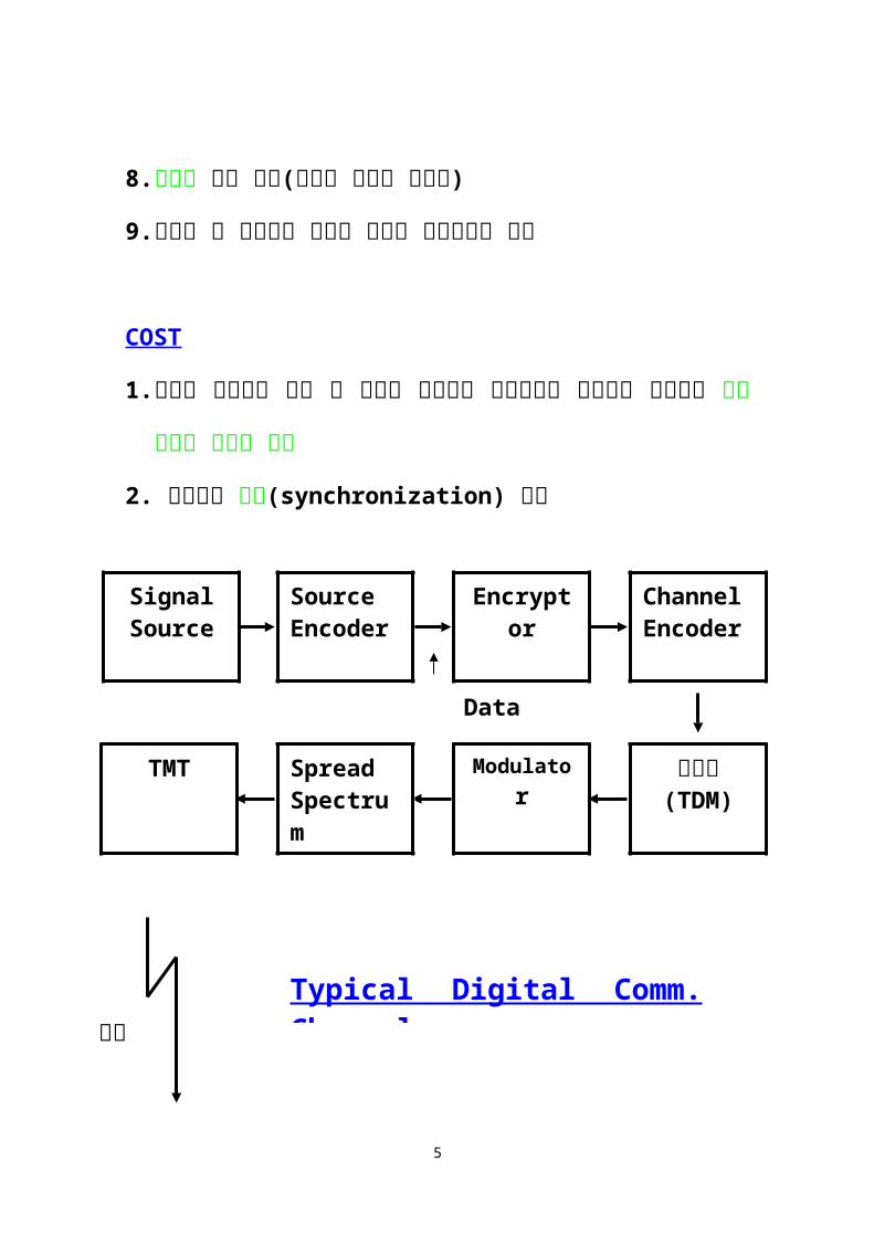
Data
Data
5
다중화(TDM)
ModulatorSpreadSpectrum
TMT
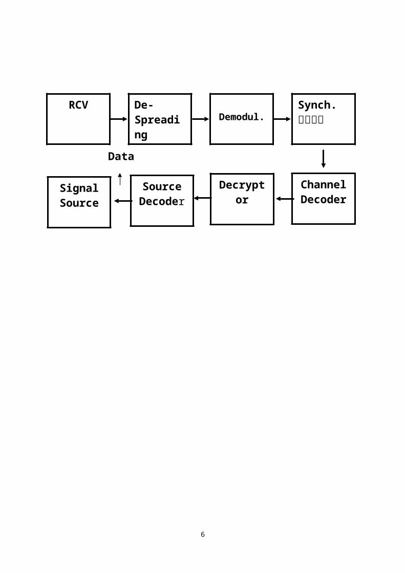
Demodul.De-Spreading
Synch.역다중화
ChannelDecoder
RCV
f(t)
채널Typical Digital Comm. Channel
DecryptorSignalSource
SourceDecoder
Digital communication
Probability 1
인터넷 공학부
6

Probability
. Set
Null Set ={ }
Universal Set Subset
A = B, A B and B AA B : (A B) A + B : (A B)
. Venn Diagram
7
A BA
A+B
ABS

Special Relation A + = A A = A + A = S AS = A = S S =
P(AB) = P(A)P(B) ; Mutually Independent
*Conditional Probability
1. P(A|M) 0
2. P(S|M) =
o 주사위 2 개를 던졌을 때 경우의 수
8

Let A = { even } B = { 6, 7, 8, 9} P(A) = P(2)+P(4)+P(6) P(12) = 2(1+3+5)/36=18/36 P(B) = P(6)+P(7)+P(8)+p(9) = (5+6+5+4)/36 = 20/36
AB = {6,8} 이 되고
P(AB) = P(6) + P(8) = (5+5)/16 = 10/36
A + B = {Even + 7 + 9} 이고
P(A+B) = P(A) + P(B) – P(AB) = (18+20-10) / 36 = 28/36
예) Dice 문제, Conditional Probability
P(B|A)=P(BA)/P(A)=(10/36)/(18/36)=10/18 = 20/36
9
1 2 3 4 5 6
1 2 3 4 5 6 7
2 3 4 5 6 7 8
3 4 5 6 7 8 9
4 5 6 7 8 9 10
5 6 7 8 9 10 11
6 7 8 9 10 11 12
White
Red

P(B|A) = P(B)
Bayes’ Rule
P(A|B) = P(B|A)P(A)/P(B) P(AB) = P(B|A)P(A) =P(A|B)P(B)
Total Probability
A1 + A2 + + An = SA1Ak = ikB = BS = B(A1 + A2 + + An) = BA1 + BA2 + + BAn
P(B) =
P(Ak|B) = P(AkB)/P(B) = P(B|Ak)P(Ak)/P(B)
=
10

예) Binary Symmetric Channel
Send Receive(Priori prob.) (Posterior Prob.)
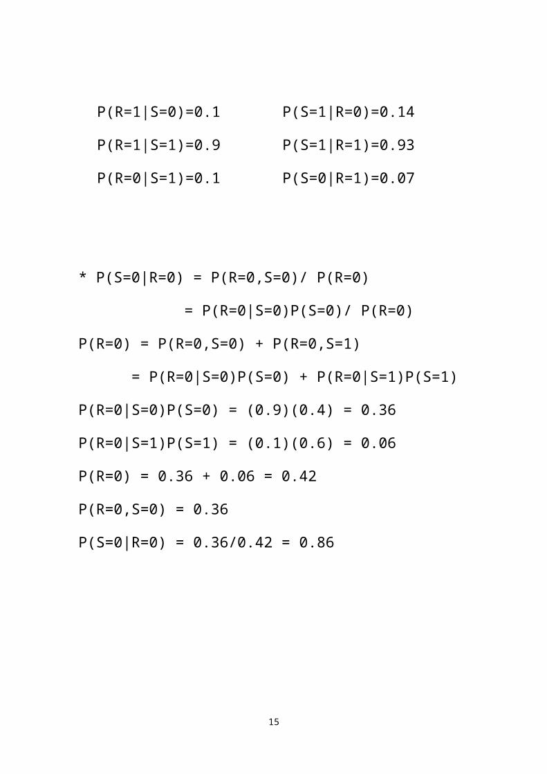
P(R=0|S=0)=0.9 P(S=0|R=0)=0.86 *
P(R=1|S=0)=0.1 P(S=1|R=0)=0.14P(R=1|S=1)=0.9 P(S=1|R=1)=0.93P(R=0|S=1)=0.1 P(S=0|R=1)=0.07
* P(S=0|R=0) = P(R=0,S=0)/ P(R=0) = P(R=0|S=0)P(S=0)/ P(R=0)P(R=0) = P(R=0,S=0) + P(R=0,S=1) = P(R=0|S=0)P(S=0) + P(R=0|S=1)P(S=1)P(R=0|S=0)P(S=0) = (0.9)(0.4) = 0.36P(R=0|S=1)P(S=1) = (0.1)(0.6) = 0.06P(R=0) = 0.36 + 0.06 = 0.42P(R=0,S=0) = 0.36P(S=0|R=0) = 0.36/0.42 = 0.86
11

12

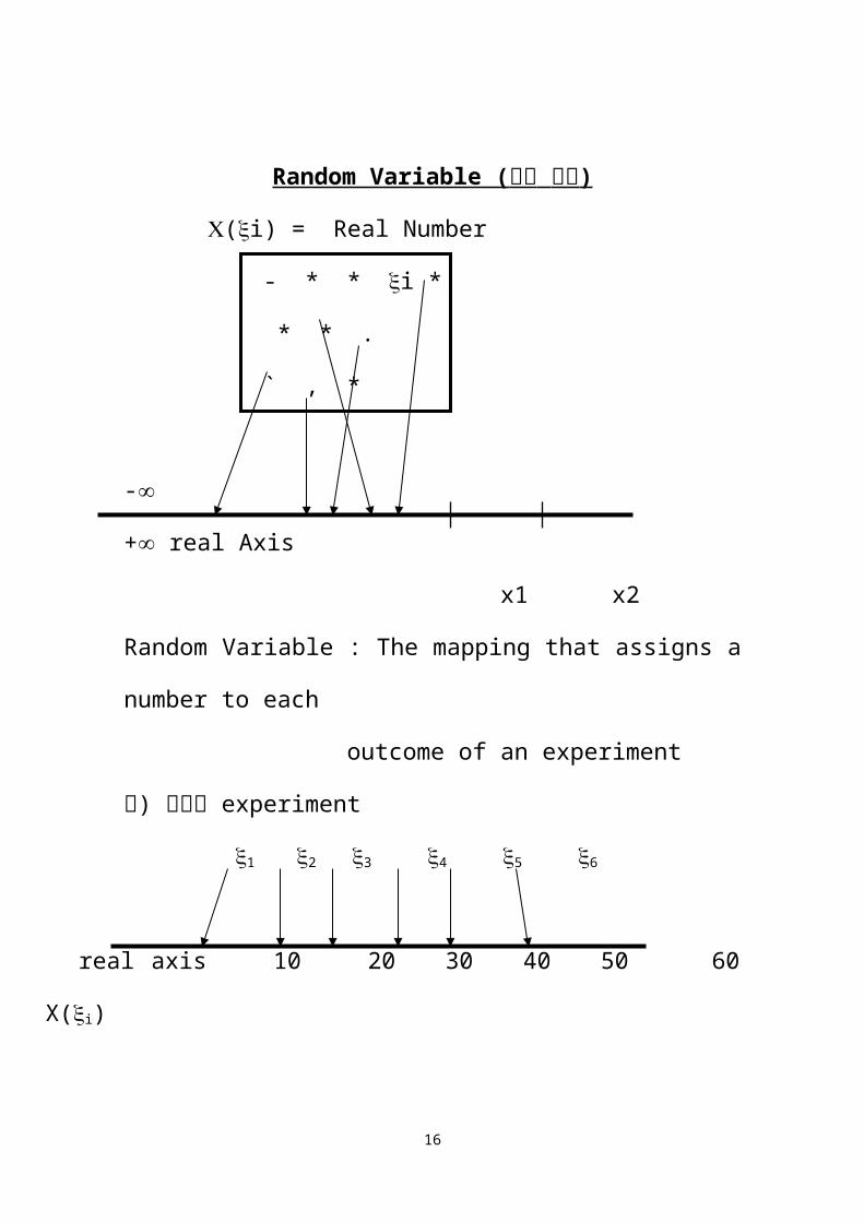
Random Variable ( 랜덤 변수 )
(i) = Real Number - * * i * * * . ` , *
- + real Axis x1 x2Random Variable : The mapping that assigns a number to each outcome of an experiment
예) 주사위 experiment
1 2 3 4 5 6
real axis 10 20 30 40 50 60 X(i)
1. Set {(i) x1} : (i) x1 인 모든 i 로 구성된 set
2. P( = ) = 0 P( = -) = 0
3. 복소수 R.V. ; z = x + iy x,y : real R.V.
Probability Distribution Function (확률분포함수)
Let x2 x1
Then
13

예) 이산적 R.V.의 분포함수
예) 연속적 R.V.의 분포 함수
Probability Density Function (확률밀도함수)
where
14
1/6
2/6
3/6
4/6
5/6
1
)(xFx
605040302010 x
주사위
예) 이산적 R.V.의 밀도함수
(주사위 실험)
Let
예) 연속적 R.V.의 밀도함수
15
1/6
)(xfx
605040302010 x
2
)(xfx
x
)20( 21)(
xxfx
)cos()( tAtv c
21
Uniform 밀도함수
Two(Multiple) R.V. Case Joint Distribution Function
Joint Density Function
Marginal Distribution & Density Functions
16

Expected (Mean) value Expected value of X
: continuous
= : discrete
Expected value of
Moment
Central moment
ex)
Variance
17

ex)
Joint moment
Joint central moment
ex)
Correlation
18
2
)(xfx
x
21

Covariance
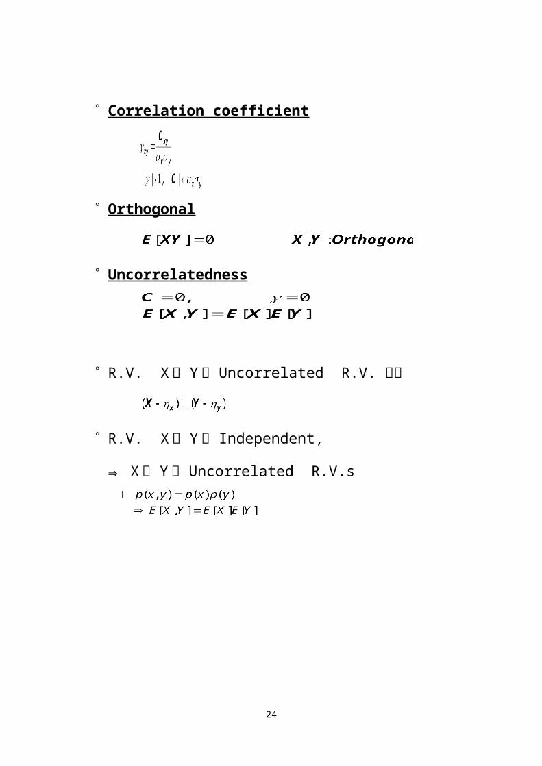
Correlation coefficient
Orthogonal Uncorrelatedness
R.V. X 와 Y 가 Uncorrelated R.V. 이면
R.V. X 와 Y 가 Independent,
⇒ X 와 Y 는 Uncorrelated R.V.s
Digital communication
19

Probability 2
인터넷 공학부
Useful probability density functions Bernoulli Trial (repeated trial)
동전던지기
S = { Head , Tail }Event A = { Head } = { Tail }
Head ⇒ X(head) 1
20

Tail ⇒ X(tail) 0
i 번째 Trial : Xi, n 회 Try
특정 Sequence 로 K 회 나올 확률 :
Number of Sequence :
Binary Communication System 0 or 1
Pb = Probability of a bit is received incorrectly
ex 1) 1000 bits 송신 data 중 3 bit 까지 error 가 날 확률
ex 2) l bit 오류정정능력이 있는 수신기를 가정
PCB = n bit 로 구성된 Block 이 오류없이 복조될 확률
오류 l bit 이하인 경우
21
0 11 1 1 0 - - - 0

Block error 확률
Gaussian p.d.f.
ex) Coin experiment 에서 1000 회 던졌을 때 Head 가 500 회
에서 510 회 나올 확률
DeMoivre-Laplace Theorem
If npq » 1 (nlarge) and k is order of np,
⇒ approximation
22

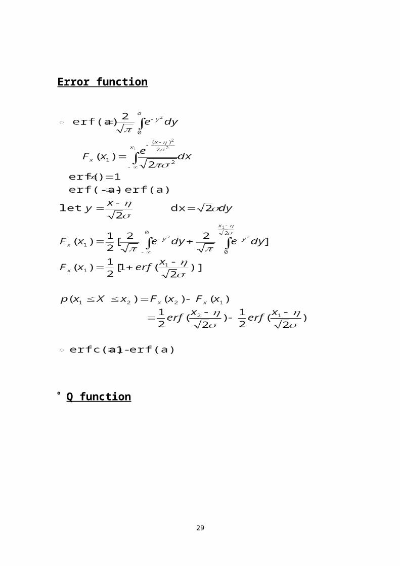
Error function
Q function
23
Central Limit Theorem X = x1+ x2+ x3+ + xn (xi : iid)
f(X) ⇒ Gaussian p.d.f.
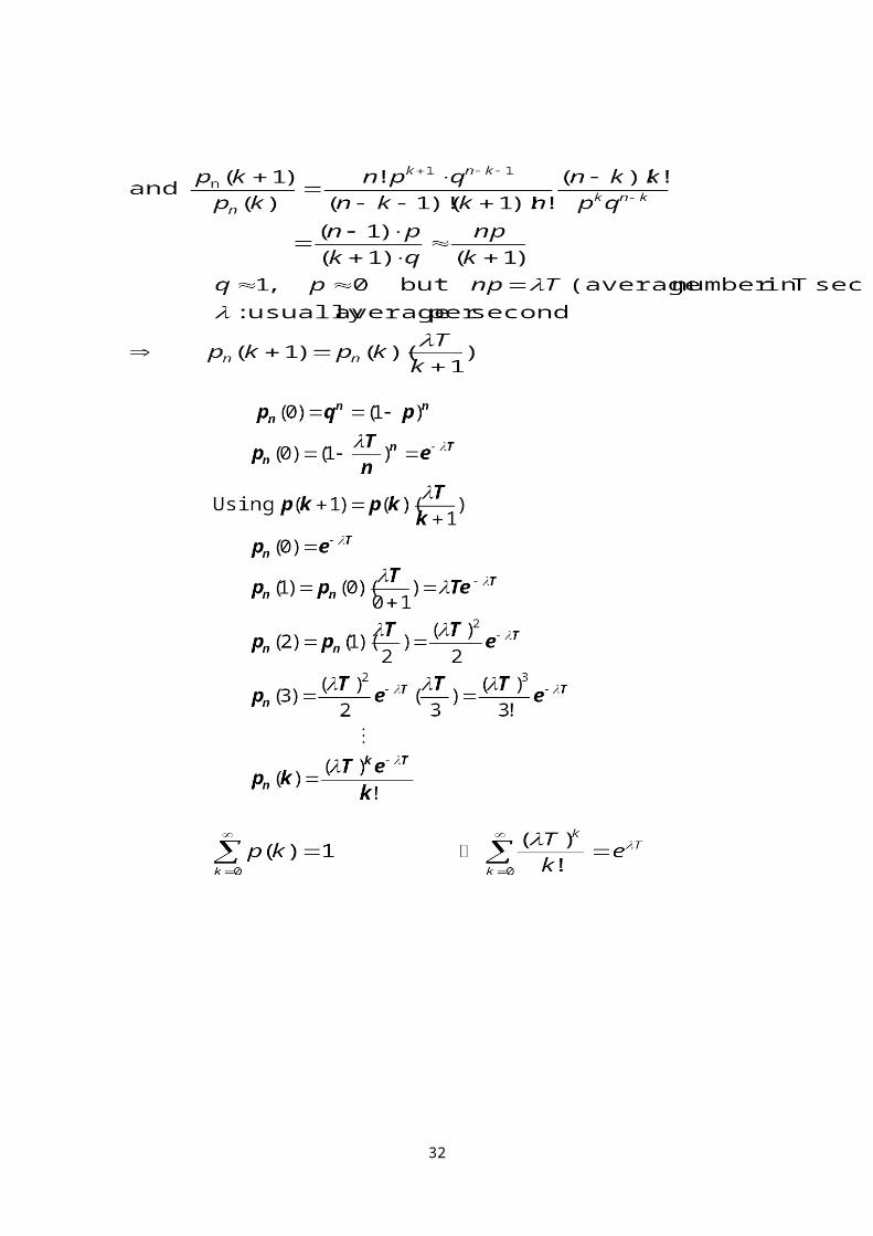
Poisson p.d.f.
Bernoulli Trial 에서 p « 1, npq np ⇒ order of 1,
K ⇒ orer of np 인 경우
approximation
따라서
: Poisson p.d.f.
24
: 단위시간당 평균발생빈도
Poisson p.d.f
Average T particles incidence in T period
Then (여기서 n » k)
25
T
t n Subdivisions

Rayleigh p.d.f.
Exponential p.d.f.
MTBF 계산에 활용
26
)( xf x
x
e1
] )( [)( 22
2
2 xuexxfx
x
)( xf x
x
axe e-x

Ricean p.d.f.
Functions of a Random Variable
27
)(xfX )(yfY)(xg

예)
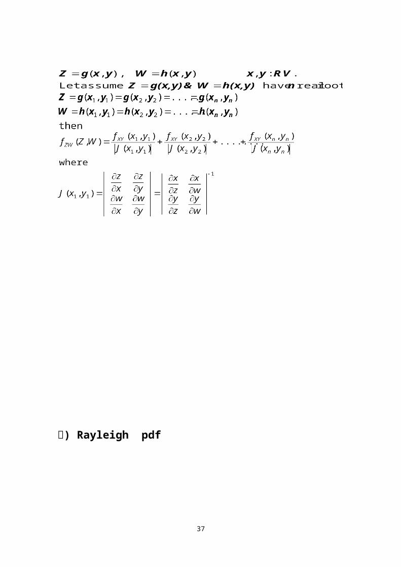
Two Functions of two random variables
28
0 ,0
baayX
ay1
ay1
X
1y
Y
a>0, y>0
예) Rayleigh pdf
29

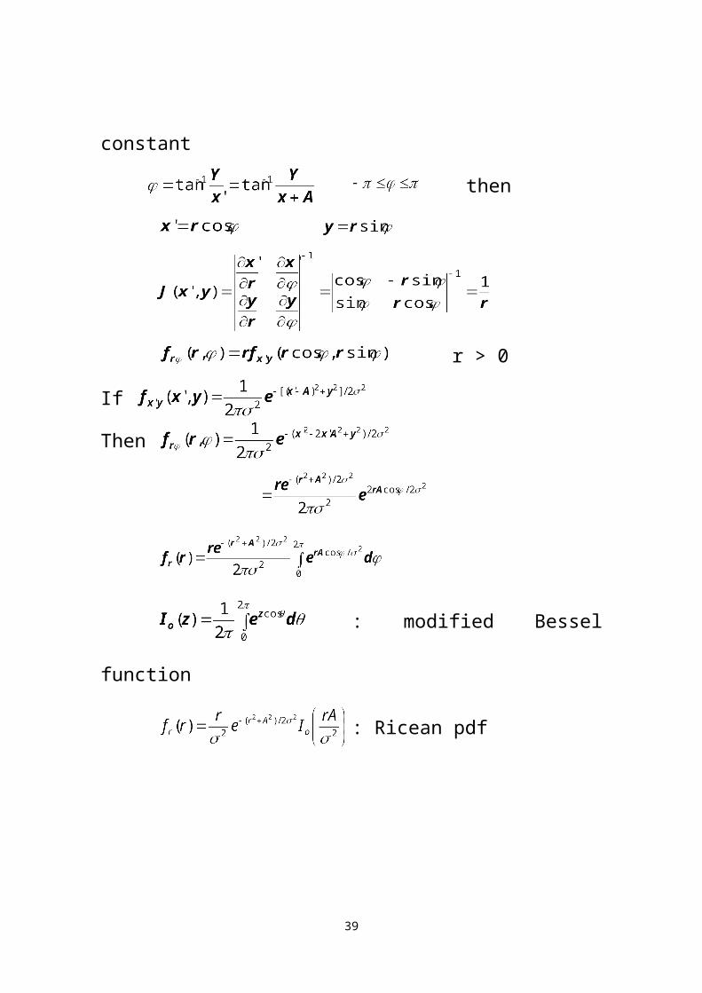
Ricean pdf Z > 0
Let x´= x+A A : constant
then
r > 0
If
Then
: modified Bessel function
30

: Ricean pdf
31
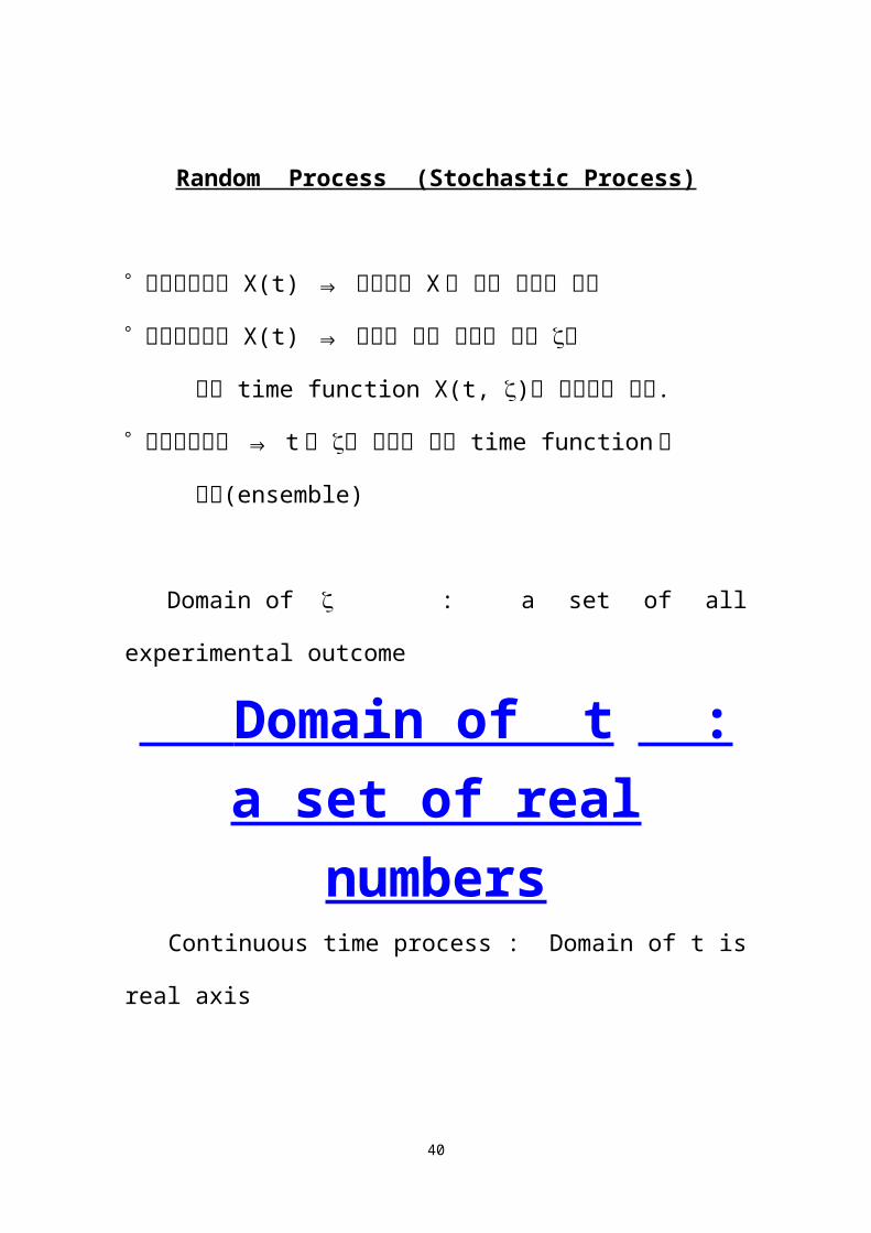
Random Process (Stochastic Process)
랜덤프로세스 X(t) ⇒ 랜덤변수 X 에 시간 개념을 도입
랜덤프로세스 X(t) ⇒ 실험의 모든 가능한 결과 에
각각 time function X(t, )를 할당하는 규칙.
랜덤프로세스 ⇒ t 와 를 변수로 하는 time function 의
집합(ensemble)
Domain of : a set of all experimental outcome
Domain of t : a set of real numbers
Continuous time process : Domain of t is real axis Discrete time process : Domain of t is a set of integers
Random process X(t) has the following interpretations.1. It is a family(or an ensemble) of functions X(t, ).
32

In this case, t and are variables2. It is a single time function (or a sample of given process).
In this case, t is a variable and is is fixed3. If t is fixed and is variable, then X(t) is a random
variable equal to the state of the given process at time t.4. If t and are fixed, then X(t) is a number Statistics of Random process1st Order statistics
2nd Order statistics
n th Order statistics
Properties
ex) white noise : zero mean
33

Cross Correlation of process X(t) and Y(t)
Cross Covariance of process X(t) and Y(t)
Stationary Process
* Strict sense stationay
모든 통계적 성질이 시간에 따라 변하지 않는 Process
In this case
* Wide sense stationay(wss)
평균과 second moment 가 시간에 따라 변하지 않는 경우
Power spectrumPower spectrum S(f) of a process X(t)
34

Spectrum Analysis Deterministic signal
Fourier transform of time function, f(t) Random signal
Fourier transform of autocorrelation function, R()Time Average
Ensemble Average :
Time Average :
Ergodicity
ergodic ⇒ 선택한 임의의 샘플이 전체 프로세스의 통계
적 성질을 대부분 보유
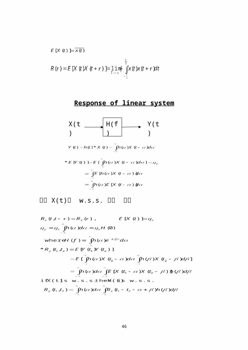
Response of linear system
35
X(t) Y(t)H(f)

또한 X(t)가 w.s.s. 라고 하면
평균 출력 전력
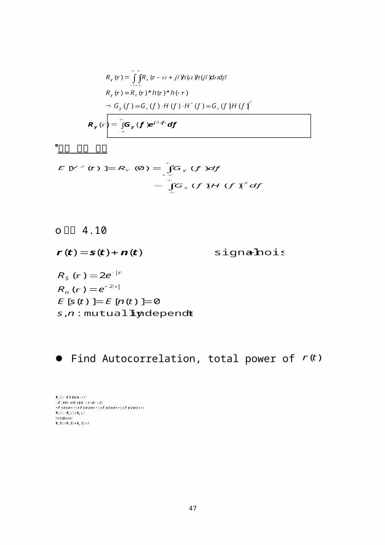
o 예제 4.10
36
Find Autocorrelation, total power of
37

Digital communication
Noise 특성
신호 대 잡음비
Matched filter
인터넷 공학부
38
Noise (Power & Spectrum)
* Spectrum Analysis
o Deterministic signal
- F.T. of time function x(t)
o Random signal
- F.T. of autocorrelation function Rn()
* Autocorrelation function Rn()
Rn(t1,t2) = E[n(t1)n(t2)]
Rn() = E[n(t)n(t+)] t2-t1 =
* Power Spectrum Gn(f)
Gn(f) = Rn()e-j2f d
Rn() = Gn(f)ej2f df
* Average Power of random signal n(t)
Rn(0) = E[n2(t)] = Pavg = n2 + E2[n(t)]
Rn(0) = E[n2(t)] = Gn(f)df
39
* Noise Power, noise n(t) is zero mean.
N = Gn(f)df E(n) = 0
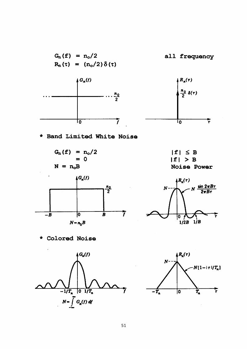
* 백색잡음(White Noise)
40

41

* Correlation Time
case 1. Rn() = 0, if 0
case 2. Rn() = 0 at = k/2B
case 3. Rn() = 0 if Tn
(1/Tn = System BW)
- For case 2,3 if 1/B (B: System BW)
Rn() 0.
- Samples of n(t) and n(t+) are uncorrelated
if 1/B.
예) B = 1Mhz, if 1/B = 1 sec
samples are uncorrelated
- If n(t) is Gaussian RV
n(t) and n(t+) are independent.
* Handling of signals in linear systems.
42

* Noise equivalent bandwidth
- Noise equivalent bandwidth
임의의 필터, H(f)equivalent ideal LPF of BW BN.
예) Input : white noise with power spectral
density no/2
Filter transfer function : H(f)
(noise equivalent BW of the filter : BN)
Output noise power, No = noH2(0)BN
43
LPFdffHH
BN
0
2
2)(
)0(1
BPFdffHfcH
BN
0
2
2)(
)(
1

* RC low pass filter
Ni(t) : zero mean Gaussian white noise with a
power spetral density no/2
RNo() = GNo(f)ej2fdf
= GNi(f)|H(f)|2 ej2f df
RNo() = (no/4RC)e-/RC
PNo = RNo(0) = (no/4RC)
Noie Equivalent Bandwidth of RC LPF
PNo = no |H(f)|2 df = noH2(0)BN
44
fRCjfH
211)(
)2(1
1)( 2
2
fRCfH

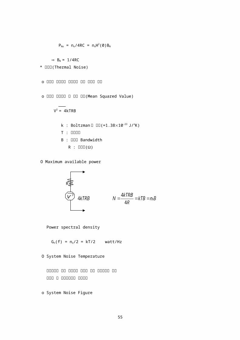
PNo = no/4RC = noH2(0)BN
BN = 1/4RC
* 열잡음(Thermal Noise)
o 소자내 전자들의 불규칙한 이동 때문에 발생
o 저항에 발생하는 열 잡음 전압(Mean Squared Value)
V2 = 4kTRB
k : Boltzman 의 상수(=1.3810-23 J/oK)
T : 절대온도
B : 시스템 Bandwidth
R : 저항값()
O Maximum available power
R
Power spectral density
Gn(f) = no/2 = kT/2 watt/Hz
O System Noise Temperature
시스템내의 모든 잡음원을 하나의 가상 잡음원으로 대체
하였을 때 가상잡음원의 절대온도
o System Noise Figure
45
NF = No/Ni = 출력잡음 Power/ 입력잡음 Power
Ni No
Narrowband Noise
white narrowband
noise noise
n(t)
BFP
BW of Noise Center Freq. Of BFP
46
H(f)
n(t) = r(t)cos[2fct+(t)]
n(t)= r(t)cos[2fct+(t)]
= r(t)cos[(t)]cos2fct-r(t)sin[(t)]sin2fct
= x(t)cos2fct-y(t)sin2fct
where r2 = x2 + y2 , = tan-1(y/x)
x(t) : inphase component
y(t) : quadrature component
x(t) and y(t) are uncorrelted, and being
Gaussian RVs, they are independent
2Cos2fct (fc=B/2 Hz)
z1(t) x(t)
n(t)
z2(t) y(t)
-2Sin2fct LPF
E[n(t)] = E[x(t)] = E[y(t)] = 0
E[n2(t)] = E[x2(t)] = E[y2(t)] = 2
z1(t) = 2n(t)cos2fct
= 2x(t)cos22fct – 2y(t)sin2fctcos2fct
= x(t)(1+cos4fct) – y(t)sin4fct
47
0 B/2
0 B/2

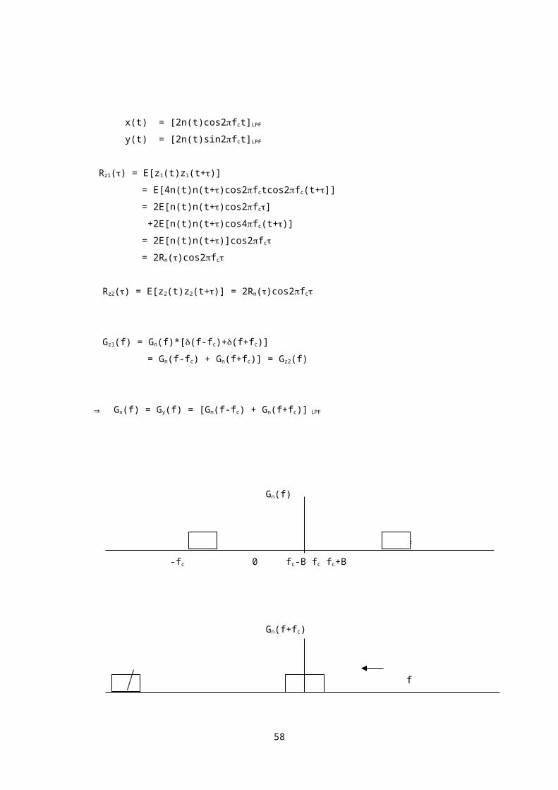
x(t) = [2n(t)cos2fct]LPF
y(t) = [2n(t)sin2fct]LPF
Rz1() = E[z1(t)z1(t+)]
= E[4n(t)n(t+)cos2fctcos2fc(t+]]
= 2E[n(t)n(t+)cos2fc]
+2E[n(t)n(t+)cos4fc(t+)]
= 2E[n(t)n(t+)]cos2fc
= 2Rn()cos2fc
Rz2() = E[z2(t)z2(t+)] = 2Rn()cos2fc
Gz1(f) = Gn(f)*[(f-fc)+(f+fc)]
= Gn(f-fc) + Gn(f+fc)] = Gz2(f)
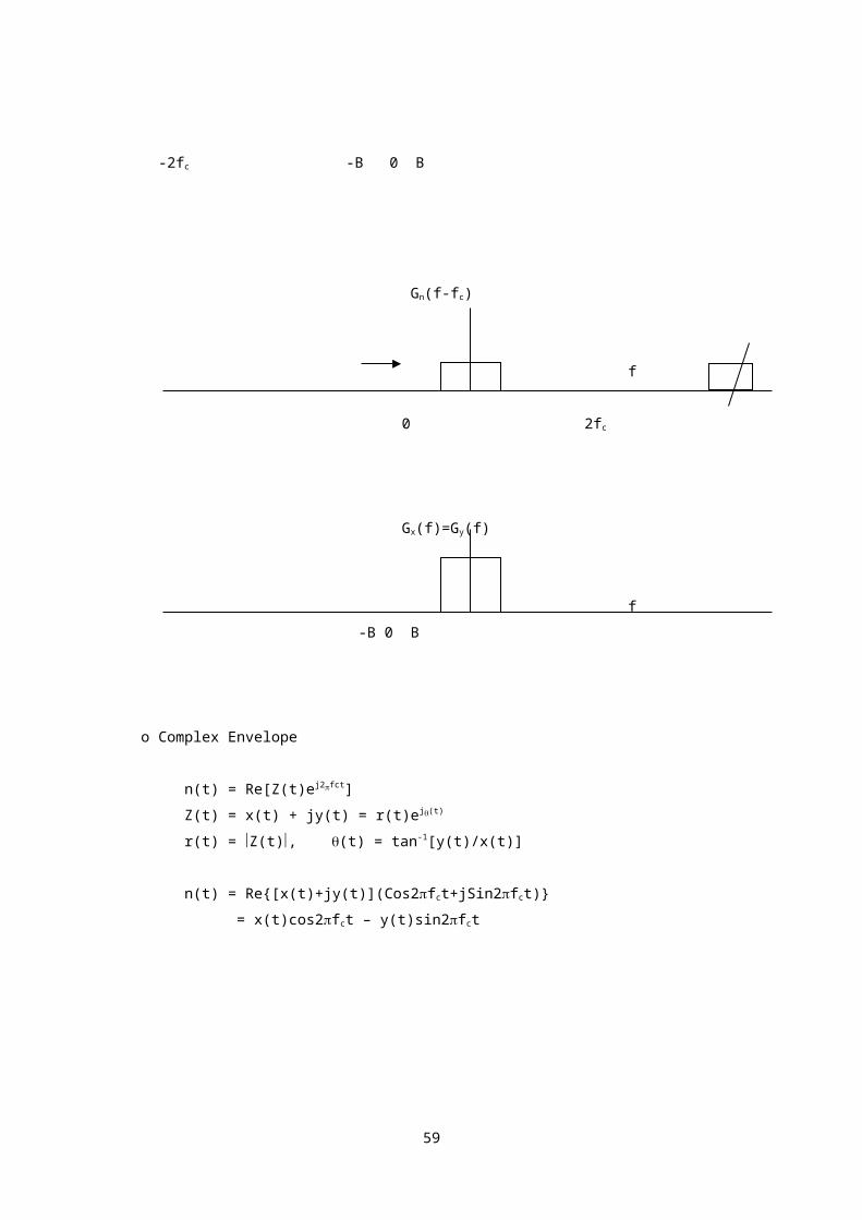
⇒ Gx(f) = Gy(f) = [Gn(f-fc) + Gn(f+fc)] LPF
Gn(f)
f
-fc 0 fc-B fc fc+B
Gn(f+fc)
f
-2fc -B 0 B
48

Gn(f-fc)
f
0 2fc
Gx(f)=Gy(f)
f
-B 0 B
o Complex Envelope
n(t) = Re[Z(t)ej2fct]
Z(t) = x(t) + jy(t) = r(t)ej(t)
r(t) = Z(t), (t) = tan-1[y(t)/x(t)]
n(t) = Re{[x(t)+jy(t)](Cos2fct+jSin2fct)}
= x(t)cos2fct – y(t)sin2fct
49

* Hilbert Transform
V(t)
H(f)
H(f) = -jsgn(f)
-jsgn(f) = -j f > 0
j f < 0
0 f = 0
H(f)
90o
0 f
-90o
h(t) = F-1[H(f)] = 1/t
= {-jsgn(f)}V(f) Hilbert transform
= (1/t)*V(t)
50
-jsgn(f)
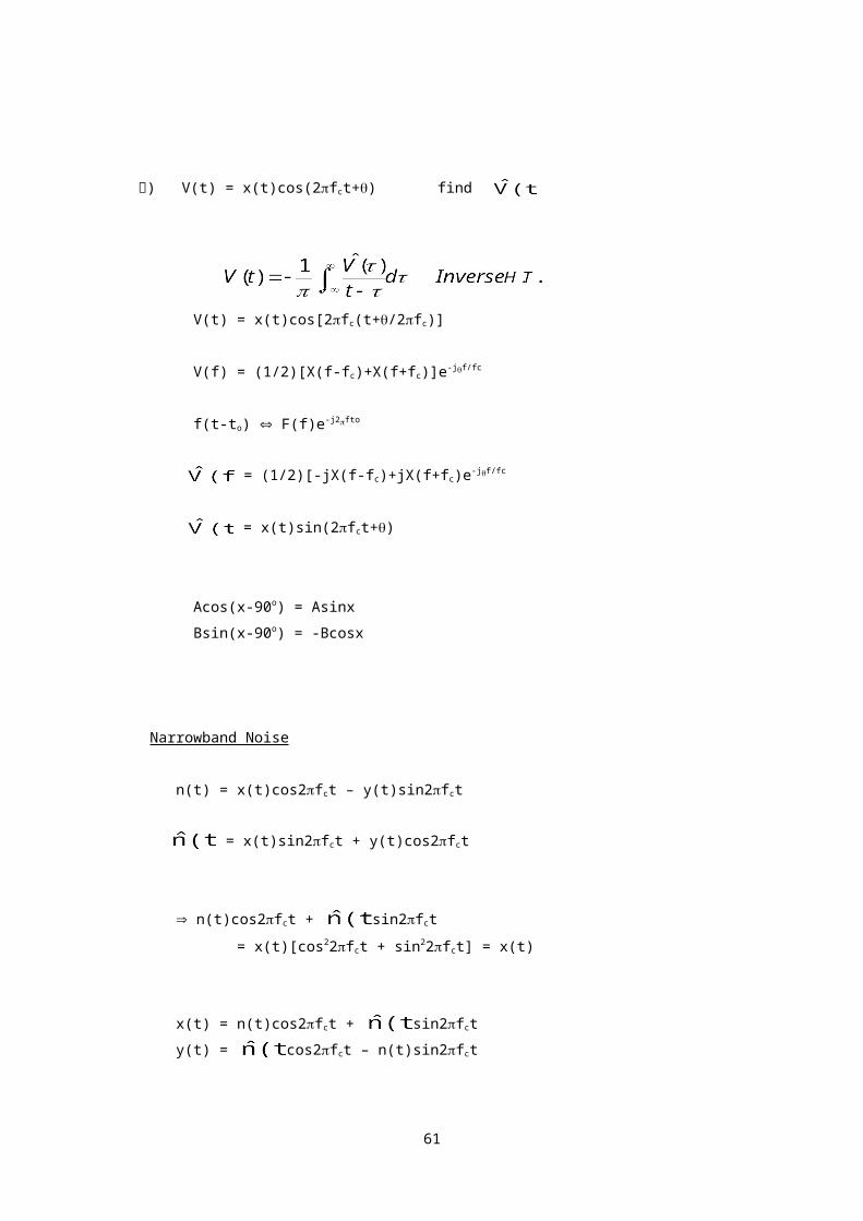
예) V(t) = x(t)cos(2fct+) find
V(t) = x(t)cos[2fc(t+/2fc)]
V(f) = (1/2)[X(f-fc)+X(f+fc)]e-jf/fc
f(t-to) F(f)e-j2fto
= (1/2)[-jX(f-fc)+jX(f+fc)e-jf/fc
= x(t)sin(2fct+)
Acos(x-90o) = Asinx
Bsin(x-90o) = -Bcosx
Narrowband Noise
n(t) = x(t)cos2fct – y(t)sin2fct
= x(t)sin2fct + y(t)cos2fct
n(t)cos2fct + sin2fct
= x(t)[cos22fct + sin22fct] = x(t)
x(t) = n(t)cos2fct + sin2fct
y(t) = cos2fct – n(t)sin2fct
51

E[x(t)] = E[y(t)] = E[n(t)] = 0
Rx() = E[x(t)x(t-)]
= E[ cos2fctcos2fc(t-)]
+E[ sin2fctcos2fc(t-)]
+E[ cos2fctsin2fc(t-)]
+E[ sin2fctsin2fc(t-)]
= (1/2) [cos2fc+cos2fc(t-)]
+(1/2) [sin2fc+sin2fc(t-)]
+(1/2) [sin2fc-sin2fc(t-)]
+(1/2) [cos2fc-cos2fc(t-)]
관계식 : = -
=
=
= = 0
대입 후 정리하면,
Rx() = Rn()cos2fc + sin2fc
동일한 방법으로 Ry()를 구하면,
Ry() = Rn()cos2fc + sin2fc
⇒ Rx() = Ry() = Rn()cos2fc + sin2fc
Rx(0) = Ry(0) = Rn(0) =
Cxy(t,t+) = E{[x(t)- ][y(t)- ]}
= Rxy() - = Rxy()
Rxy() = E[x(t)y(t-)]
= E[ cos2fctcos2fc(t-)]
52

+E[ sin2fctcos2fc(t-)]
-E[ cos2fctsin2fc(t-)]
-E[ sin2fctsin2fc(t-)]
= [cos2fccos2fc(t-)]
+ [sin2fccos2fc(t-)]
- [cos2fcsin2fc(t-)]
- [sin2fcsin2fc(t-)]
정리하면
Rxy() = Rn()sin2fc - cos2fc
동일한 방법으로,
Ryx() = -Rn()sin2fc + cos2fc
⇒ Rxy(0) = - = = 0
Cxy(0) = Rxy(0) = 0
⇒ 동일 시각 t=t1 에 채취한 sample x(t1)과 y(t1)은
Uncorrelate 되어있다
⇒ Sn(f)가 fc 에 대하여 대칭인 경우,
Cxy() = Rxy() = 0 for all
* 신호대 잡음비(SNR)
수신신호 = 정보신호 + 잡음
53

복조된 신호의 품질(BER) (정보신호/ 잡음)
예) input S/N = 10 (10log10=10dB)
output S/N = 5 (10log5=7dB)
F = 10/5 = 2 (10log2=3dB)
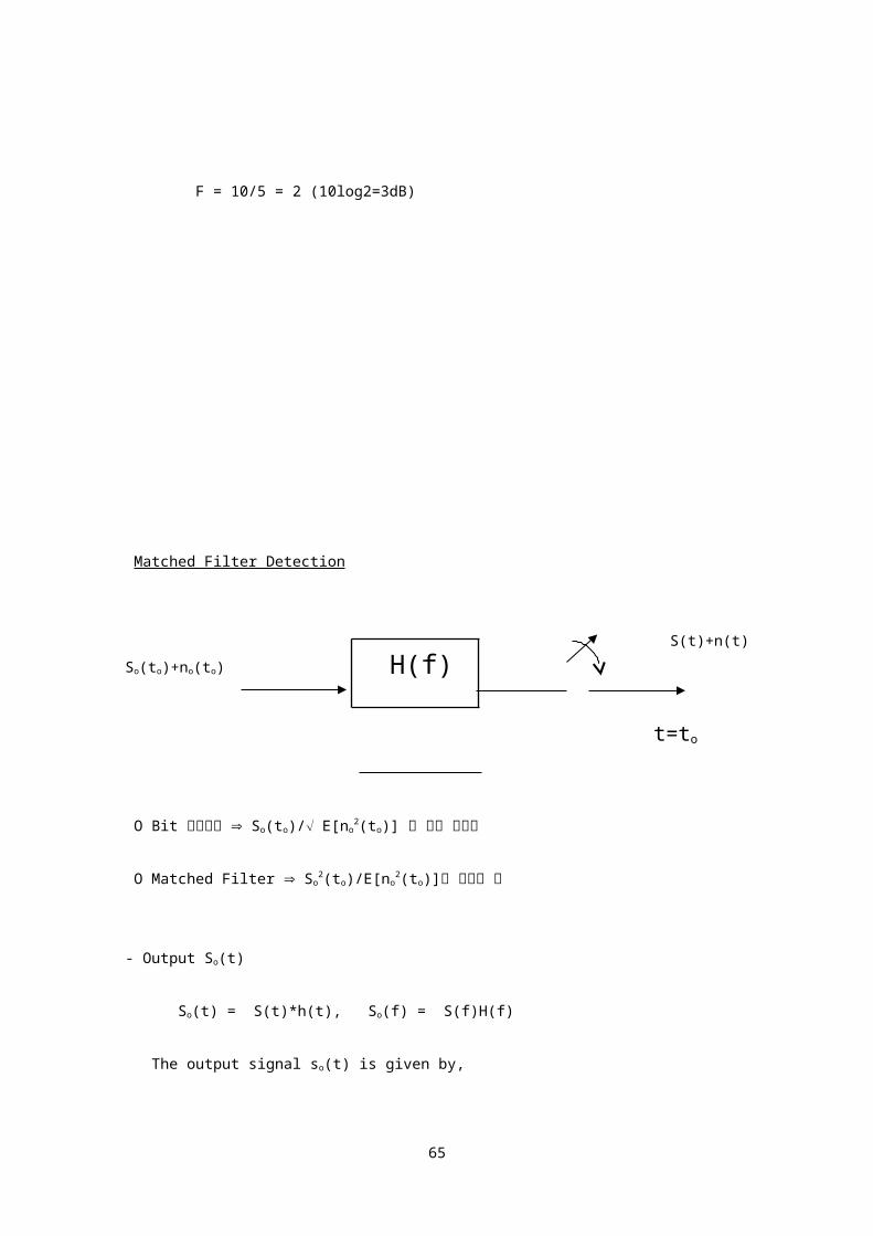
Matched Filter Detection
S(t)+n(t) So(to)+no(to)
t=to
54
H(f)
O Bit 오류확률 So(to)/ E[no2(to)] 에 따라 결정됨
O Matched Filter So2(to)/E[no
2(to)]를 최대로 함
- Output So(t)
So(t) = S(t)*h(t), So(f) = S(f)H(f)
The output signal so(t) is given by,
So(t) = S(f)H(f)ej2ftdf
The magnitude of So(t) at the sampling time to
A = |So(to)| = | S(f)H(f)ej2ftodf |
- Input white noise power spectrum
Gn(f) = no/2
Output noise power spectrum
Gno(f) = (no/2)|H(f)|2
The average output noise power
N = E[no2(to)] = (no/2) |H(f)|2 df
- Energy of the input pulse(Parseval’s Theorem)
E = S2(t)dt = |S(f)|2 df E:constant
55

- A2/N 가 maximize 되는 H(f)를 구해보면,
(Maximize A2/N = Maximize A2/EN)
A2 | S(f)H(f)ej2ftodf |2
=.
EN (no/2) |S(f)|2 df |H(f)|2 df
By Schwarz’s inequality,
| S(f)H(f)ej2ftodf|2 |S(f)|2 df |H(f)|2 df
noA2/2EN 1
noA2/2EN = 1 : The ratio is maximum
| f(f)g(f)df|2 |f(f)|2 df |g(f)|2 df
Equality holds if
f(f) = kg*(f) K : constant
Let f(f)=H(f), g(f) = S(f)ej2fto
H(f) = K[S(f)ej2fto]* = KS*(f)e-j2fto
Equivalent time domain equation is,
h(t) = KS(to-t)
56

The response(output) of the matched filter to
input S(t) is,
So(t) = S(f)H(f)ej2ftdf
= K |S(f)|2ej2f(t-to)df
Sampling time, t = to에서 So(t)의 크기
|So(to)| = K |S(f)|2df = KE = A
So(to) 크기는 signal energy E 에 비례
The average output noise power
N = (no/2) |H(f)|2 df
= (no/2)K2 |S(f)|2df = (no/2)K2E
Matched filter 출력단에서의 최대 SNR 은,
The impulse response of a matched filter
H(f) = K[S(f)ej2fto]* = KS*(f)e-j2fto
57
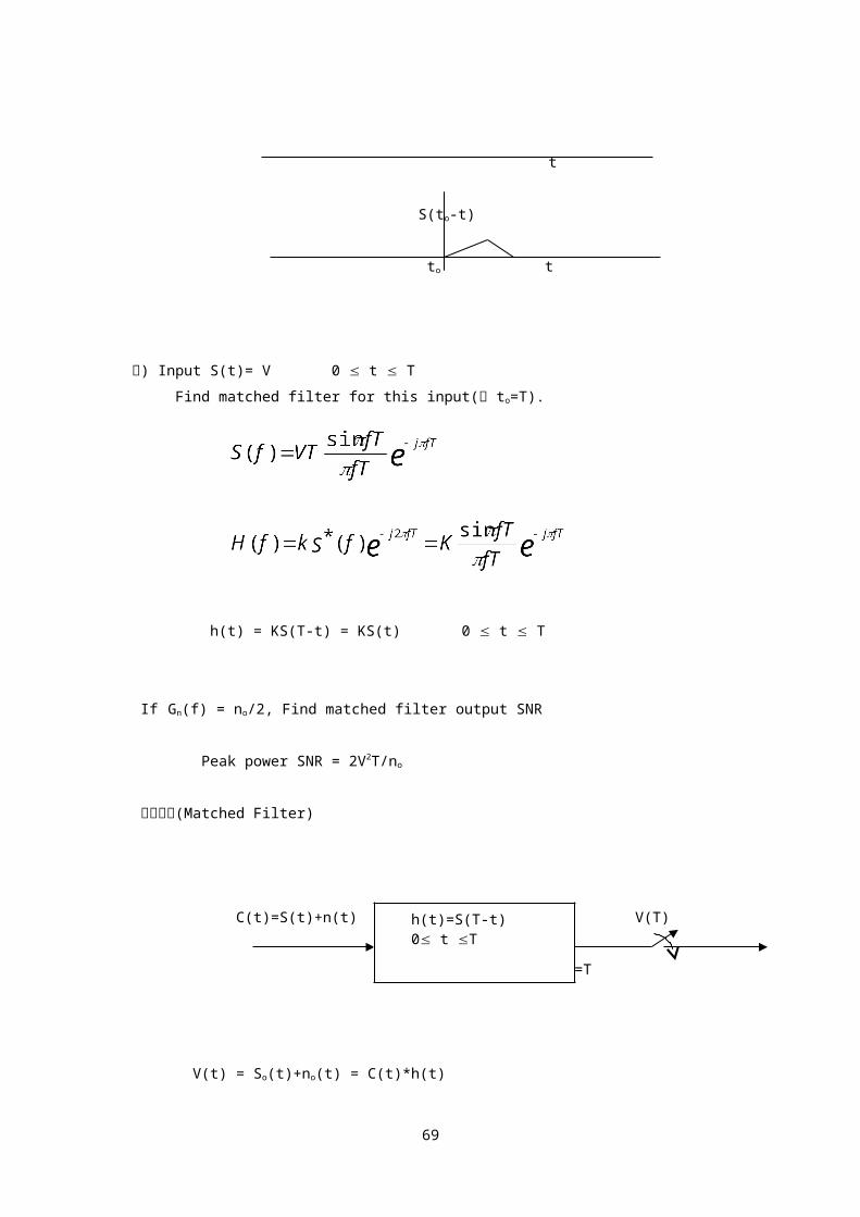
h(t) = KS(to-t)
S(t)
t
S(-t)
t
S(to-t)
to t
예) Input S(t)= V 0 t T
Find matched filter for this input(단 to=T).
h(t) = KS(T-t) = KS(t) 0 t T
If Gn(f) = no/2, Find matched filter output SNR
Peak power SNR = 2V2T/no
정합필터(Matched Filter)
58
C(t)=S(t)+n(t) V(t) V(T)
t=T
V(t) = So(t)+no(t) = C(t)*h(t)
= C()h(t-)d
= C()S(T-t+)d
at time, t=T
V(T) = So(T)+no(T)
= C()S()d
= [S()+n()]S()d
S(t)+n(t) So(T)+no(T)
t=T
S(t)
Correlator
59
h(t)=S(T-t) 0 t T
dt

Remarks
1. Matched filter Correlator
2. Matched filter 도출 시 전제조건
- Additive noise is White Noise
- No intersymbol interference
3. Additive noise 가 nonwhite noise(colored
noise) 인 경우의 matched filter,
Gcn(f) : colored noise power spectrum
Digital communication
60
Analog to Digital 변환
Sampling theorem
Quantization
Companding
61

인터넷 공학부
* A/D 변환(Analog ⇒ Digital)
analog digital
신호 sampling Quantization Binary 신호
x(t) coding
o PCM(Pulse Code Modulation)
1. analog 신호 x(t)를 대역폭 B Hz 인 LPF 로 주파수 제한.
2. 대역제한된 신호를 fs ≥2B sample/sec 율로 표본화
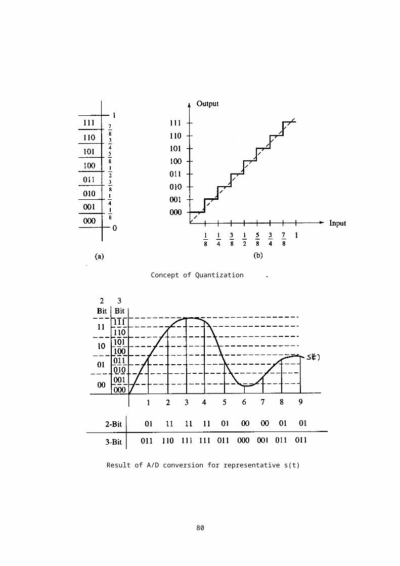
3. 표본값을 N 개의 레벨중 하나로 양자화
4. 양자화된 신호를 n(log2N) bit 의 binary code 로 변환
o 음성의 디지털화
62
표본화 양자화 부호화

- 파형 부호화(Waveform Coding)
예) 64kbps PCM(8 kHz 표본화율ⅹ 8 bit /표본)
- Vocoding(≤4.8kbps)
Sampling Theorem
o Ideal Sampling
xδ(t)
x(t) xs(t)
63

x(t)(t-to)= x(to)(t-to)
X(f)*(f-nfs)=X(f-nfs)
xs(t)=x(t)xδ(t)=x(t) (t-nTs)
= x(nTs)(t-nTs)
Xs(f)=X(f)*Xδ(f)=X(f)*[(1/Ts) (f-nfs)]
= (1/Ts) X(f-nfs)
x(t) : Band limited signal (limited to fm)
▲ Sampling frequency가 2fm 이상(fs≥2fm)
sampling된 신호 xs(t)로부터 원래의 신호
x(t)를 재생 가능
▲ Nyquest frequency: fs = 2fm
(최대주파수 성분의 2 배의 sampling 주파수) ▲ Sampling frequency 가 Nyquest frequency 이하인 경우
⇒aliasing 이 발생
예) 음성 : 300Hz – 3400Hz
Nyquest frequency : 6800Hz 실제 sampling rate : 8000/초
xs(t)로부터 원래의 신호 x(t)를 재생하기 위한
LPF의 cutoff freq. = 3400Hz
64
o Natural Sampling
65

(Pulse폭이 τ 인 펄스열 사용)
o Sample and Hold operation
66

X(f) : 주기가 2fm인 f의 함수 한주기(T=2fm=1/to)
67

o Errors in Sampling
- Quantization error
- Truncation error
- Error due to aliasing
68
69
Concept of Quantization
Result of A/D conversion for representative s(t)

Concept of Quantization
Serial Quantizer
70

71
Binarycounter

Counting Quantizer
72
The parallel

Parallel Quantizer
* Gray Code
- 인접 Digit간 1 bit변화
- Bit Error 영향 최소화
- Binary Gray 변환
b1 g1
bk gk bk-1 k2
- Gray Binary 변환
g1 b1
gk bk bk-1 k2
73

* Digital to Analog Conversion(A/D변환)
74

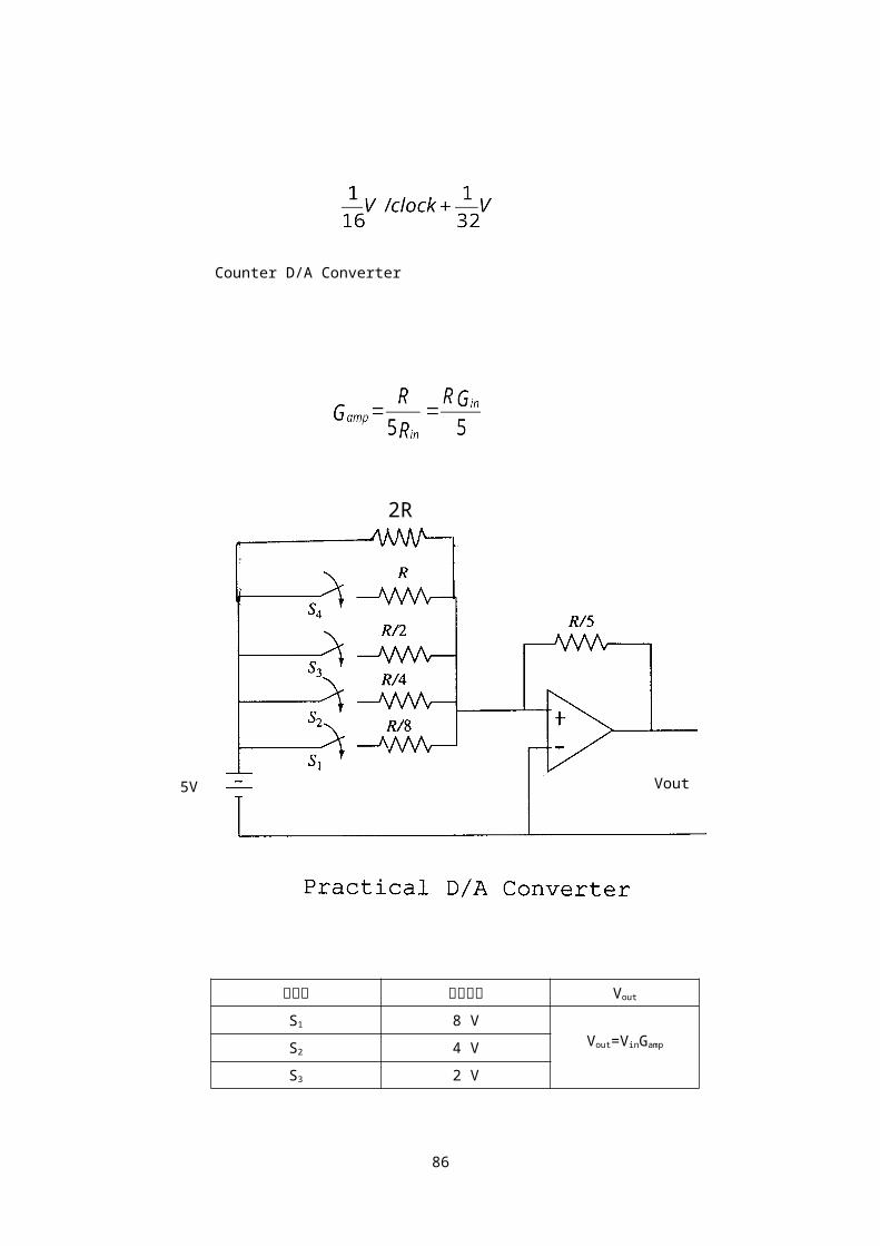
Counter D/A Converter
스위치 기여출력 Vout
S1 8 VVout=VinGamp
=기여출력S2 4 V
S3 2 V
75
2R
Vout5V

S4 1 V
Bias 0.5 V
예) 디지털 입력, 0011 아나로그 출력, 7/32
S1,S2 off, S3,S4 on
Vout = VinGamp = 5(7/10) = 3.5(V)
Normalized Output 3.5/16 = 7/32
X Y C
76
VoltageQuantizer
Encoder

xo yo=3/2a c=101
* Quantization Error(Noise)
1/a -a/2≤≤a/2 -a/2 0 a/2
E[] = 0
σ2 = E[2] = a2/12
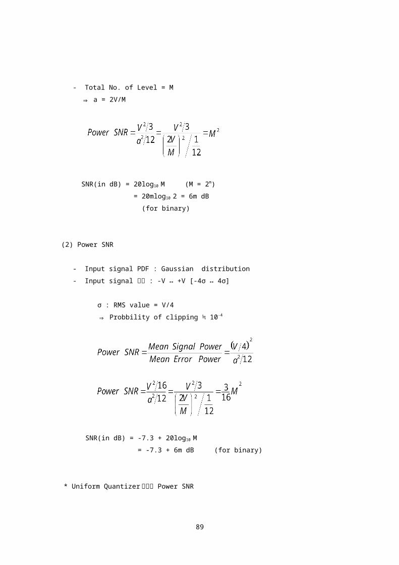
(1) Power SNR
- Input signal PDF : Uniform distribution
- Input signal 크기 : -V ↔ +V
1/2v
-v 0 v x
- Total No. of Level = M
⇒ a = 2V/M
77

SNR(in dB) = 20log10 M (M = 2m)
= 20mlog10 2 = 6m dB
(for binary)
(2) Power SNR
- Input signal PDF : Gaussian distribution
- Input signal 크기 : -V ↔ +V [-4σ ↔ 4σ]
σ : RMS value = V/4 ⇒ Probbility of clipping ≒ 10-4
SNR(in dB) = -7.3 + 20log10 M
= -7.3 + 6m dB (for binary)
* Uniform Quantizer 에서의 Power SNR
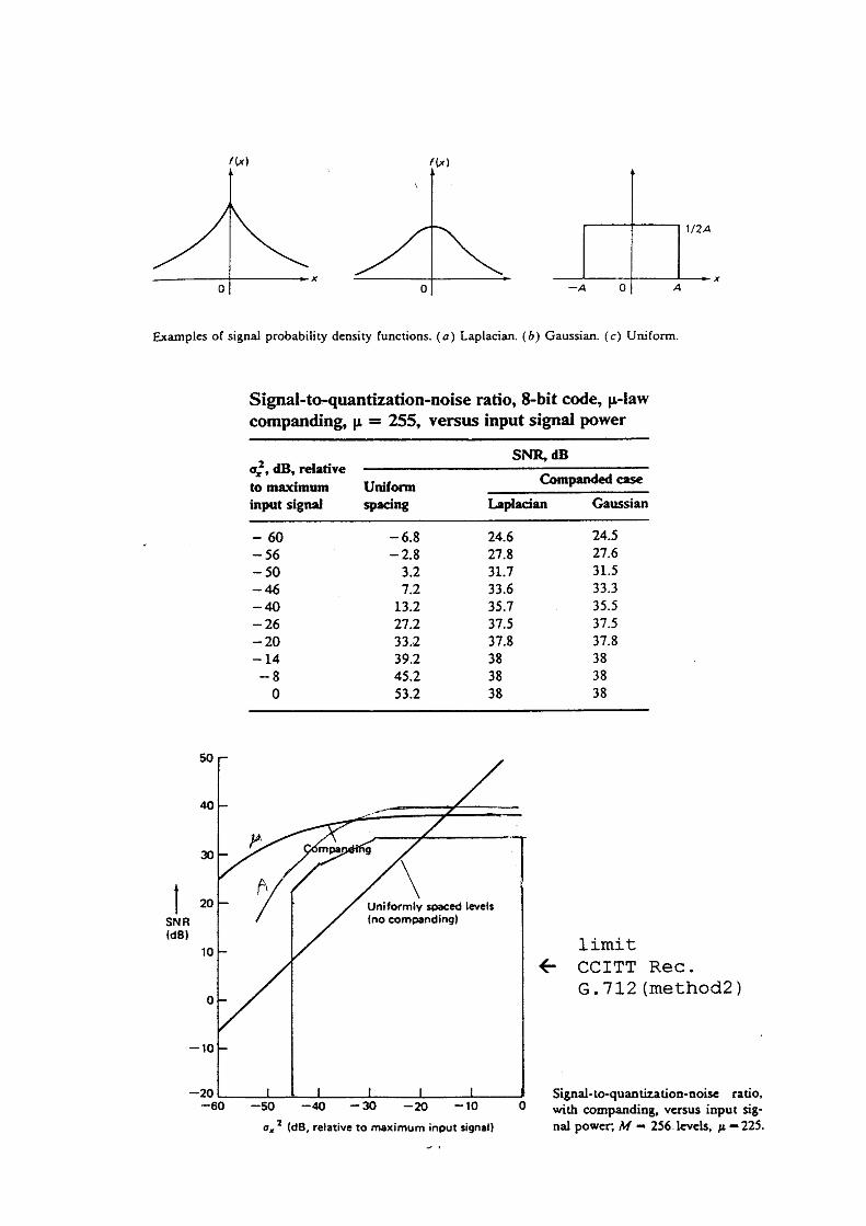
1. SNR depends on the input signal power σs2
⇒ 소리가 작아지면 SNR 저하됨
2. 음성신호의 dynamic range는 40dB 이상됨
78

V
20dB SNR needs 75dB
⇒ We would need 12
20dB to 13 bits per
low signal speech sample level 35dB
noise level
⇒ 이러한 문제들을 해소하기 위하여 companding
technique을 사용.
* Companding
Nonlinear
quantizer
- 작은 입력신호 : quantization level수를 증가
큰 입력신호 : quantization level수를 감소
79
Compression amplifier
Uniformquantizer
Expansion amplifier
decoder
- μ law companding :
let x = x’/V then,
- normalized μ law companding :
- US =255 law companding
80

Signal to Noise ratio for law compander :
where
: normalized signal power
: average quantization noise power
: 255 or other number
81

82

83

- A law companding
Typical value of A : 87.6
84

- 예) Quantization with companding
Y
1
0.7
-1 -0.2 0.2 1 X
-0.7
-1
- M=256 Level
- AY=2/256, 동일간격
- For input
Slope, S1=3.5
X간격,
- For input
Slope, S1=0.3/0.8=3/8
85
X간격,
* Assume input signal pdf is uniform
1. peak 0.01V input
2. peak 1V input
86

Digital communication
PCM/ DPCM
Delta 변조
T1 & E1 System
Baseband signal waveform
87

Channel capacity
Entropy Encoding
인터넷 공학부
* Differential Pulse Code Modulation(DPCM)
- Sample S(nTs)와 이 Sample 의 추정값 (nTs)의 차이송신
- 추정값은 이전 Sample들을 활용하여 구함
- Quantize해야 할 신호의 dynamic range가 PCM의
경우보다 작음 => PCM보다 sample당 적은 bit필요
88
- 추정값을 이전 Sample하나만을 활용하여 구하는 경우
추정값 :
(nTs)=AS[(n-1)Ts] i=1 경우
e(nTs)=S(nTs)- (nTs)=S(nTs)-AS[(n-1)Ts]
Mean square error of e(nTs)
Mse=E[e2(nTs)]
=E[S2(nTs)]+A2E[S2(n-1)Ts]-2AE[S(nTs)S(n-1)Ts]
=R(0)(1+A2)-2AR(Ts)
Error can be minimized when,
d(mse)/dA = 2AR(0)-2R(Ts) = 0 or
ES[(n-1)Ts]{S(nTs)-AS[(n-1)Ts]} = 0
⇒ A = R(Ts)/R(0)
* 수신기(DPCM)
89

e(nTs) S(nTs)
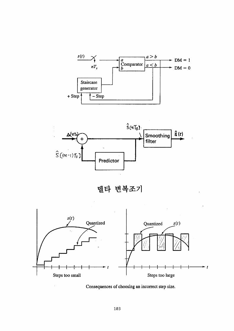
* 델타변조(Delta Modulation)
- Sample S(nTs)와 바로 전 sample S[(n-1)Ts]의 차이송신
- one bit quantization 사용 (+1 또는 –1)
- Sampling rate(음성) : 16kbps~32kbps
- Key factor : step size, sampling rate
- impulse 잡음에 강함
90
Decoder
Predictor
입력
출력+
+

91

Input : S(t)=Asin2fmt
Slope : ds/dt=2fmAcos2fmt
Max. slope of input : 2fmA
To prevent slope overload:
92

Output power of S(t)
Max. quantization error :
PDF of error : Uniform distribution
Mean square quantization error Nq
For sinusoidal input, SNR is
Maximum SNR for no slope overload case,
Using fs = 2fmA
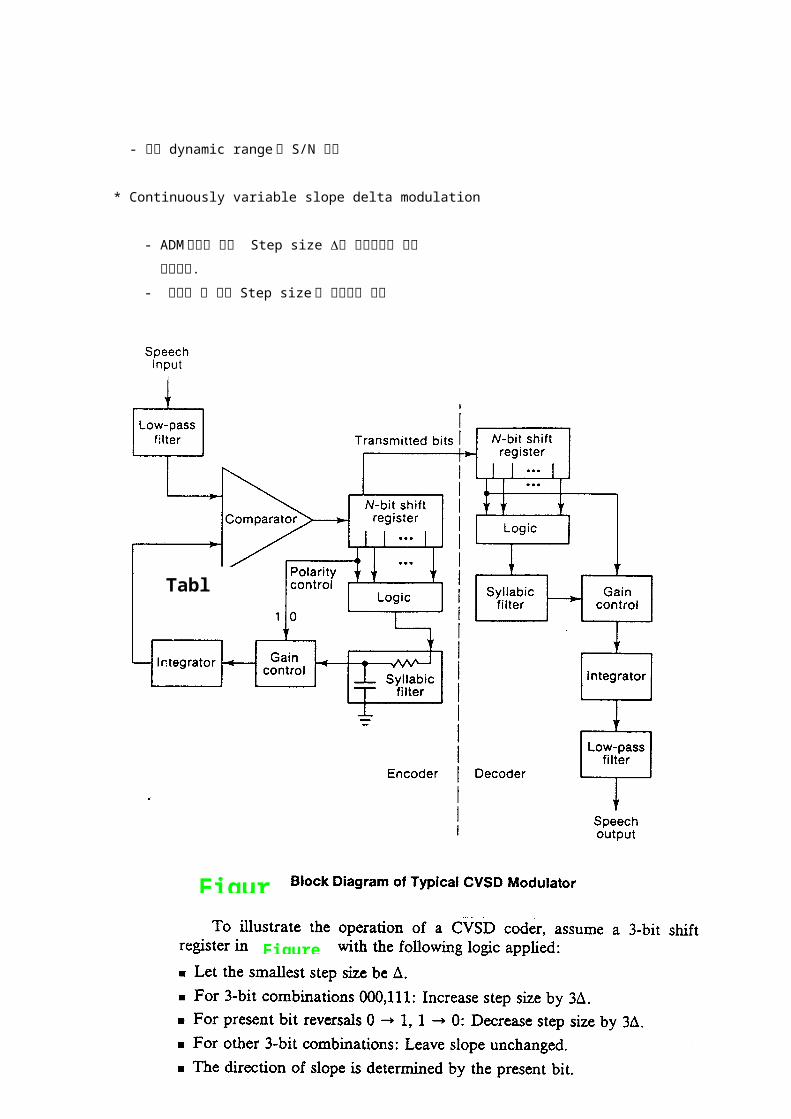
* Aaptive Delta Modulation(ADM)
- Step size 를 입력신호에 따라 변화시킴.
93
- 변화할 수 있는 Step size는 사전 결정되어 있씀
(예: 1, 2, 4, 6, 8, 16 등)
- 입력 dynamic range와 S/N 향상
94
Delta modulator SNR, sine wave input
Fs=fs/fm
Table :

* Continuously variable slope delta modulation
- ADM에서와 같이 Step size 를 입력신호에 따라
변화시킴.
- 변화할 수 있는 Step size 가 제한되지 않음
95
Figure
Figure A

*Effect of multiple A/D and D/A conversions
96
Intelligibility vs. number of CVSD conversions

Multiplexing
*FDM : Frequency Division Multiplexing
*TDM : Time Division Multiplexing
*STDM : Statistical Time Division Multiplexing
*TDM/WDM : TDM/Wavelength Division Multiplexing
97
Comparison of conventional TDM with statistical TDM
Idle time slot

98
* Bell system T1
- 음성(전화) 24 채널 TDM 장비
- 채널당 : 8khz sample/sec×8bit/sample=64kbps
- frame : 8bit×24ch + 1bit = 193bits/frame- 전송속도 : 193bits × 8000frame/sec = 1.544Mbps- Signalling : In-band signalling- 사용국 : 미국, 캐나다, 일본등
- T2 : 6.312Mbps(4T1), T3 : 44.736Mbps(7T3)
* E1 system
- 32 채널 TDM 장비
(음성 30채널 + 1 signalling 채널+ 1 control 채널) - 채널당 : 8khz sample/sec×8bit/sample=64kbps
- 전송속도 : 64kbps × 32ch = 2.048Mbps- Signalling : out-band signalling(또는 CCS)- CCITT(⇒ITU-T) 표준방식
99

- 사용국 : 유럽 각국
요구되는 특성
100

- Timing information
- Reduced Bandwidth
- Spectral shaping
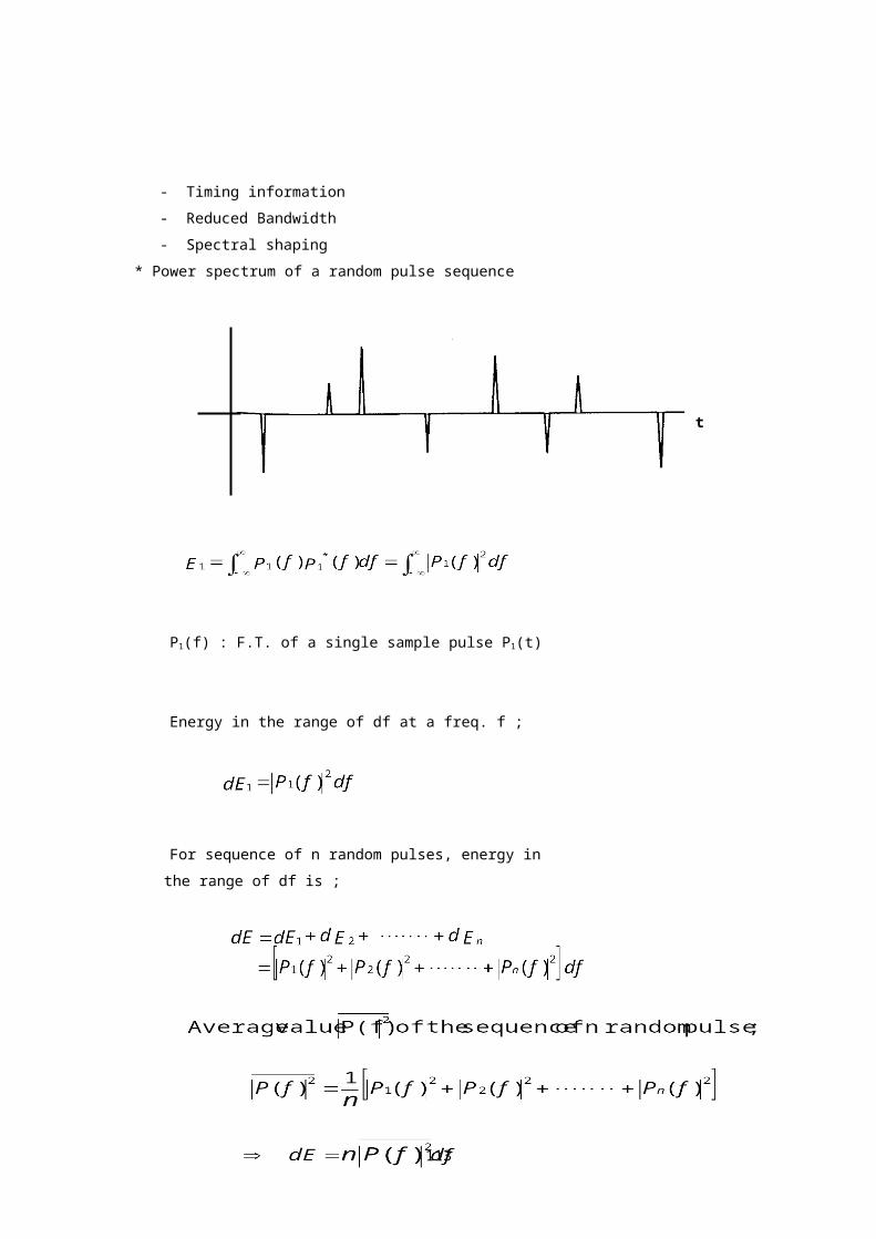
* Power spectrum of a random pulse sequence
P1(f) : F.T. of a single sample pulse P1(t)
Energy in the range of df at a freq. f ;
For sequence of n random pulses, energy in
the range of df is ;
101
t

펄스간 평균시간 간격 => Ts then,
n펄스가 발생하는 시간 => nTs
Pavg : average power of a signal S(t)
G(f) : power spectrum of a signal S(t)
Power spectrum in the frequency range df ;
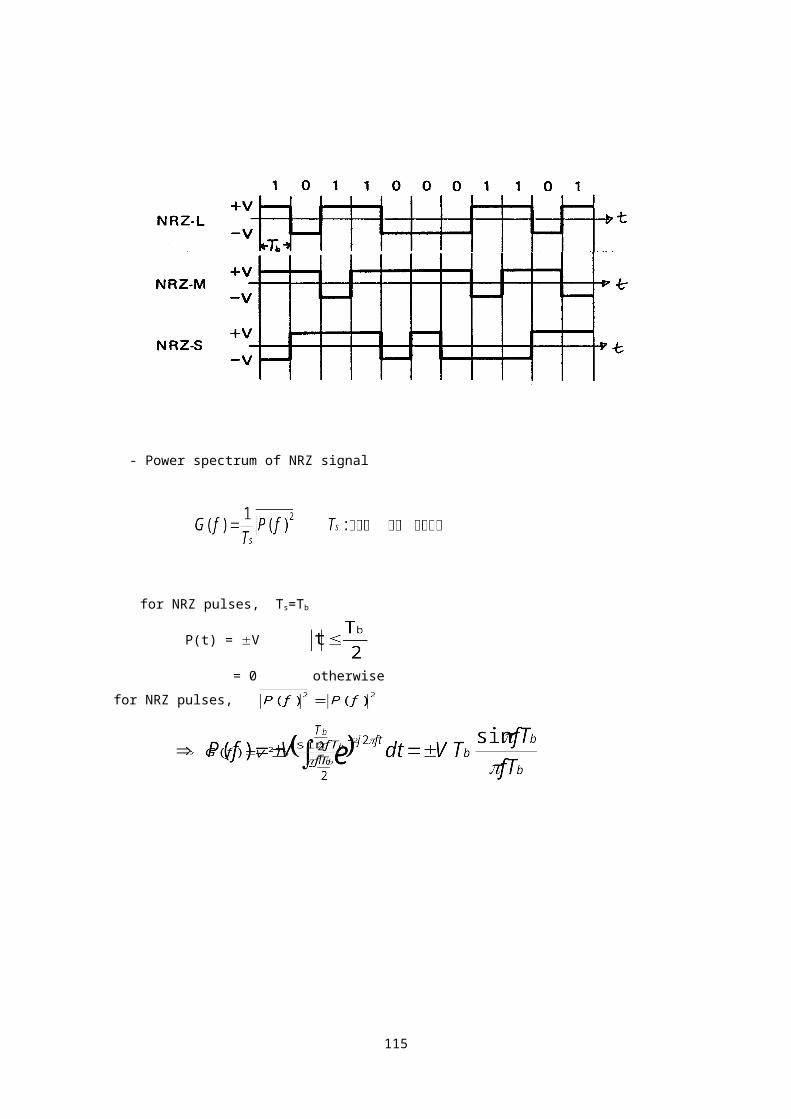
* NRZ(nonreturn to zero) signal
102
- Power spectrum of NRZ signal
for NRZ pulses, Ts=Tb
P(t) = V
= 0 otherwise
for NRZ pulses,
103

Power spectrum of NRZ signal
- f=Rb 이하의 주파수에 91% power가 포함됨.
- RZ format보다 상대적으로 적은 주파수 대역 점유
- 데이터에 연속된 1 또는 0 포함 시, 파형변화가 없어 Timing 문제 발생가능
- NRZ bipolar format경우, data inversion시 수신기에서 식별곤란 1
과 0 바뀔 수 있음
104

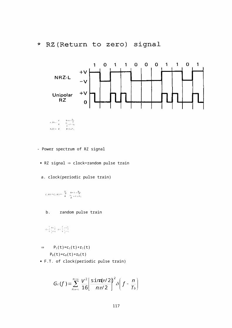
- Power spectrum of RZ signal
RZ signal clock+random pulse train
a. clock(periodic pulse train)
b. random pulse train
P1(t)=c1(t)+r1(t)
P0(t)=c0(t)+r0(t)
F.T. of clock(periodic pulse train)
105
F.T. of random pulse train
for random pulse component,
106

- RZ unipolar format signal은 DC 성분포함
전송로가 DC 통과 시키지 않을 경우 문제발생 가능
RZ-AMI(alternate mark inversion) 신호 사용
- NRZ format 보다 많은 주파수 대역폭 점유
- Timing 유지에 유리
RZ-AMI signal
107

* Biphase signal
- Power spectrum of biphase signal
for biphase pulses,
108

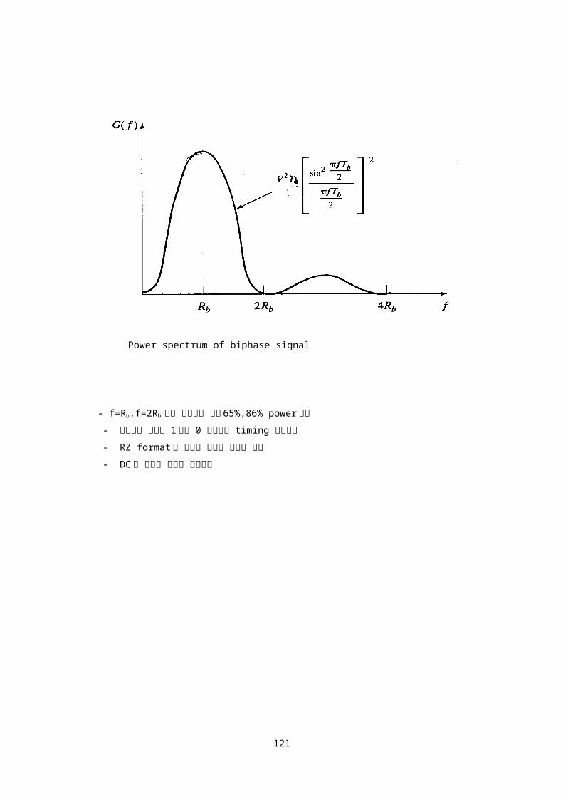
Power spectrum of biphase signal
- f=Rb,f=2Rb 이하 주파수에 각각 65%,86% power포함
- 데이터에 연속된 1또는 0 포함시도 timing 문제없음
- RZ format과 동일한 주파수 대역폭 점유
- DC를 포함한 저주파 성분없음
109

* Channel Encoding
Entropy Coding :
송신할 message의 길이(bit 수)를 최소화
Error Control Coding :
전송로에서 발생하는 오류정정으로 오류영향 최소화
Encryption :
정보비화
* Information and Entropy
Information content of a message x
Ix=log(1/Px)
여기서 Px : probability of occurrence of x
Px 小 Ix 大
예) Px=1 Ix=0
if base 2 logarithms are used,
Ix=log2(1/Px) bits
Entropy
Entropy : average amount of information
per message
110

예) 6개 레벨 x1,x2,x3,x4,x5,x6, 중 1개를 송신하는
시스템
P(x1)= P(x2)=1/4
P(x3)= P(x4)= P(x5)= P(x6)=1/8
Ix1=Ix2=log24=2 bits
Ix3=Ix4=Ix5=Ix6=log28=3 bits
예) 256 level quantized speech
Levels Pi
110 ~ 127
60 ~ 109
30 ~ 59
-30 ~ 29
-60 ~ -31
-110 ~ -61
-128 ~ -111
0
0.001
0.005
0.01
0.005
0.001
0
= 50(0.001)log2(1/0.001)
+30(0.005)log2(1/0.005)
+60(0.01)log2(1/0.01)
+30(0.005)log2(1/0.005)
+50(0.001)log2(1/0.001)
111

= 7.276 bits/message
For binary message
P(x2)=1-P(x1)
P(x1)=P(x2)=1/2 H=1 bit/message(최대치)
Entropy of binary communication system
Entropy H :
P(x1)=P(x2)== P(xn)=1/n 일 경우 최대
112
* Channel Capacity
Rate of information flow
R = rH bits/sec
여기서 r=message per sec., Hentropy
Shannon-Hartley Channel Capacity
C = Blog2(1+S/N) bits/sec
여기서 B : channel bandwidth in Hz
S/N : 신호 대 잡음비(N=noB, AWGN)
- Case 1, N 0 S/N C
Case 2, B C 1.44S/no
- Shannon limit
S=REb C=R R : data rate
B 경우, C=1.44REb/no=1.44CEb/no
Eb/no=0.69 Eb/no=-1.6dB
Shannon limit : Eb/no=-1.6dB
113

* Entropy Encoding
Average length of the code words
여기서 L : average length
Li: length of ith message(code word)
Pi: Probability of ith message
For binary coding,
L H
여기서 L : average code word length
H : entropy
예) 4개 레벨 x1,x2,x3,x4중 1개를 송신하는 시스템
P(x1)= P(x2)=1/8
P(x3)= 1/4, P(x4)=1/2
case 1. x1=000, x2=001, x3=01, x4=1
case 2. x1=00, x2=01, x3=10, x4=11
114
message probability P(xi)가 다른 경우는,
code word길이가 동일하지 않는 경우에
shortest code length를 얻음.
발생빈도가 큰 message에 짧은 code word할당
예) Encode five messages s1,s2,s3,s4,s5
P(s1)= 1/16, P(s2)=1/8
P(s3)= 1/4, P(s4)=1/16,
P(s5)= 1/2
Huffman code
115

- Huffman code
1. message를 발생 Probability가 큰 것부터 적은
것 순으로 정렬
2. 맨 밑의 2개 Probability를 합하여 다시 정렬,
2개만 남을 때까지 반복
3. 오른쪽부터 code할당(0또는 1), 왼쪽으로 가면서
2개로 갈라진 경우만 1bit씩 추가로 code할당.
116
coding 결과 average code length와 entropy,
⇒ 동일 길이 code 사용 시, L = 3 bit
Shannon-Fano code
1. message를 발생 Probability가 큰 것부터 적은
것 순으로 정렬
2. Probability를 합한 것이 각각 1/2또는 1/2에 근접하도록 2개의
그룹으로 분할
3. 2개의 그룹에 각각 0또는 1, code할당
4. 분할된 그룹 내에서 Probability를 합한 것이 각각 절반 또는 절반에
근접하도록 2개의 subgroup으로 다시 분할
5. 2개의 subgroup그룹에 각각 0또는 1, 1bit씩 추가로 code 할당
6. 4, 5를 subgroup그룹에 2개의 message가 남을 때 까지 반복
Shannon-Fano code
Word ProbabilityS5 1/2 0
S3 1/4
S2 1/8
117

S1 1/16
S4 1/16
Word ProbabilityS3 1/4 Code word 10
S2 1/8
S1 1/16 Code word 11
S4 1/16
Word ProbabilityS2 1/8 Code word 110
S1 1/16Code word 111
S4 1/16
118

Word ProbabilityS1 1/16 Code word 1110
S4 1/16 Code word 1111
119

Digital communication
Symbol & Frame Synchronization
Intersymbol interference & pulse
shaping
Eye pattern
인터넷 공학부
120
Baseband Digital Communication
송수신기 동기(Synchronization)
o Carrier 동기
o Symbol(bit) 동기
o Frame 동기
Data Transmission
o 비동기식 전송(Asynchronous Transmission).
o 동기식 전송(Synchronous Transmission)
동기식 전송방식에서 송수신기간 bit 동기
o RZ signal format : 협대역 BPF 또는 PLL 사용 하여
송신된 데이터 신호로부터 clock pulse 도출
- NRZ signal format 에 비하여 bit 당 에너지가 1/2(3dB)임.
bit error rate Eb/no
- NRZ signal format 에 비하여 2 배 전송 대역폭 필요.
o NRZ signal format : no periodic component
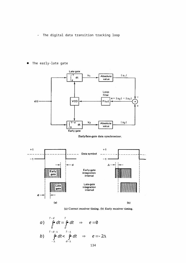
- The early-late gate
- The digital data transition tracking loop
121

The early-late gate
122
2)
0)0
edtdtb
edtdta
T
d
dT
T
d
dT

* Data Transition Tracking loop(DTTL)
123
Data transition tracking loop

* Timing Jitter 의 영향
124

예) BER 10-3 을 유지하기 위한 신호대 잡음비(SNR)
-Timing jitter 가 없는경우(e/T=0) Eb/no=6.7dB
-Timing jitter 10% 경우(e/T=0.1)Eb/no=12.9dB
-10% Timing jitter 6.2dB 큰 power 필요
동기식 전송방식에서 송수신기간 Frame 동기
125

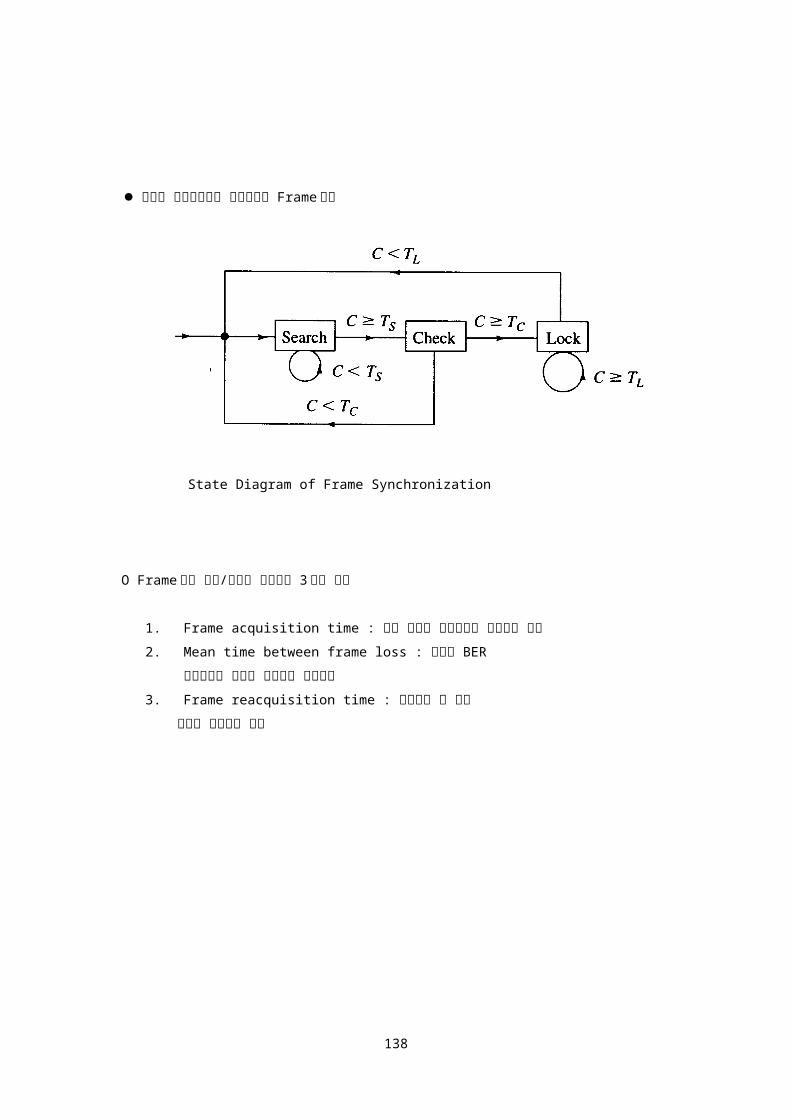
동기식 전송방식에서 송수신기간 Frame 동기
State Diagram of Frame Synchronization
O Frame 동기 특성/성능을 나타내는 3 가지 요소
1. Frame acquisition time : 초기 동기를 완료하는데 소요되는 시간
2. Mean time between frame loss : 규정된 BER
조건하에서 동기가 이탈되는 평균시간
3. Frame reacquisition time : 동기이탈 후 재동
기까지 소요되는 시간
126

동기식 전송방식에서 송수신기간 Frame 동기
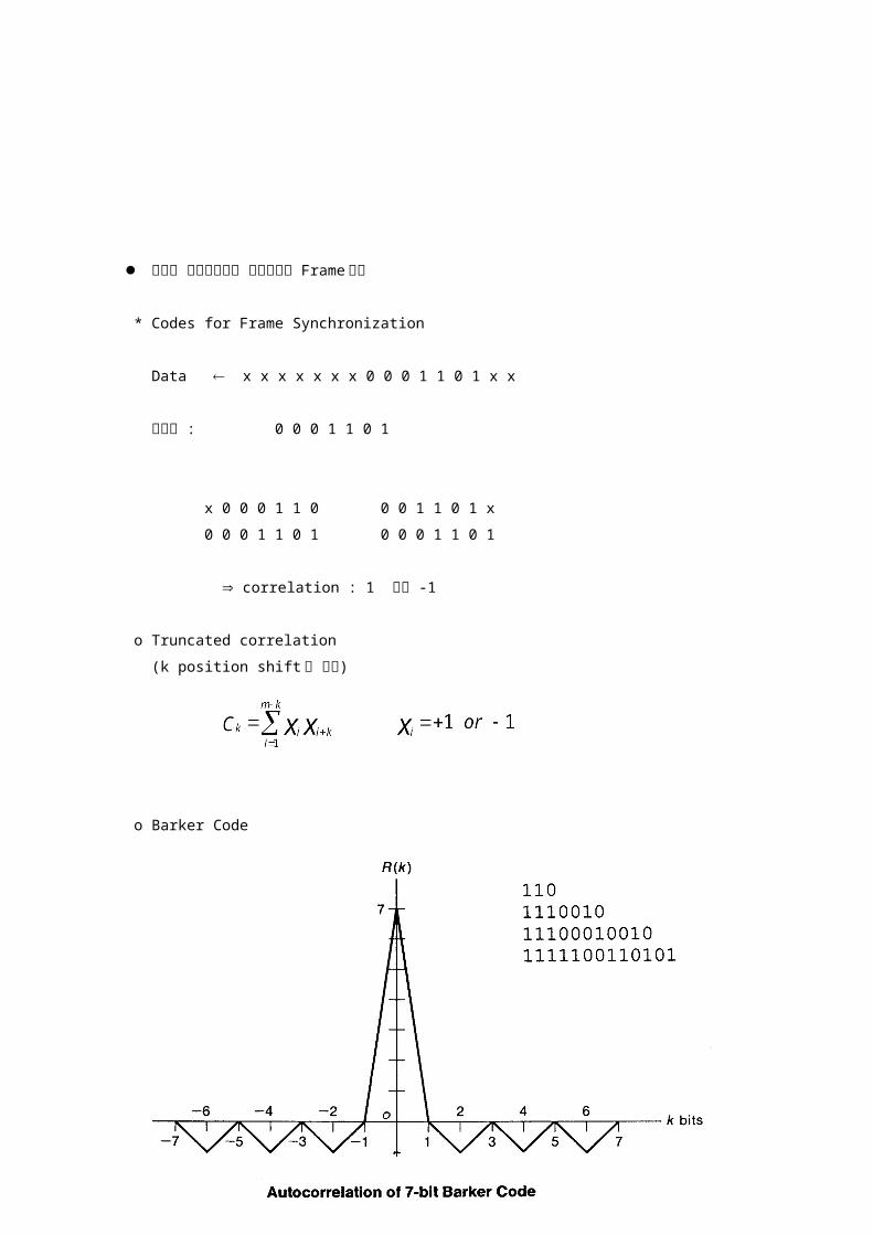
* Codes for Frame Synchronization
Data x x x x x x x 0 0 0 1 1 0 1 x x
수신기 : 0 0 0 1 1 0 1
x 0 0 0 1 1 0 0 0 1 1 0 1 x
0 0 0 1 1 0 1 0 0 0 1 1 0 1
correlation : 1 또는 -1
o Truncated correlation
(k position shift 된 경우)
o Barker Code
127

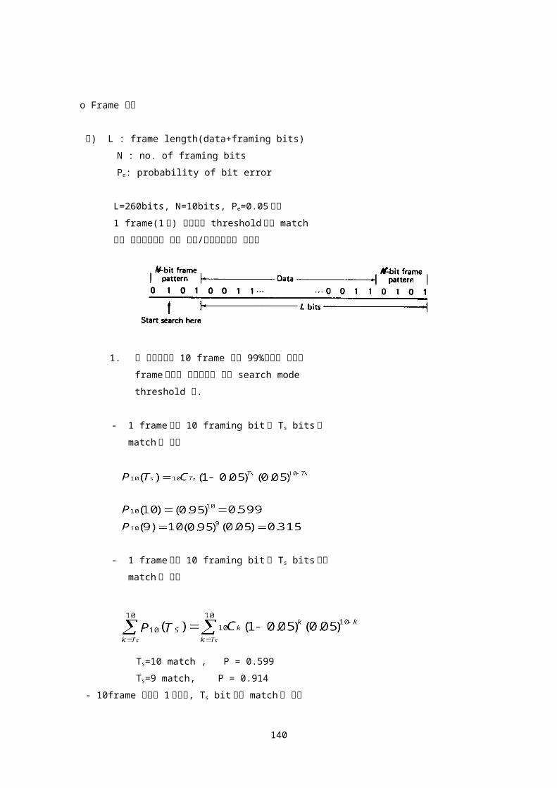
o Frame 동기
예) L : frame length(data+framing bits)
N : no. of framing bits
Pe: probability of bit error
L=260bits, N=10bits, Pe=0.05 이며
1 frame(1 회) 점검하여 threshold 이상 match
되면 초기동기완료 또는 동기/유지확인으로 판단함
1. 위 시스템에서 10 frame 내에 99%이상의 확률로
frame 동기가 이루어지기 위한 search mode
threshold 값.
- 1 frame 내의 10 framing bit 중 Ts bits 가
match 될 확률
- 1 frame 내의 10 framing bit 중 Ts bits 이상
match 될 확률
Ts=10 match , P = 0.599
Ts=9 match, P = 0.914
- 10frame 내에서 1 회이상, Ts bit 이상 match 될 확률
128

Ts=10, Pm = 1-(1-0.599)10=0.9999
Ts=9, Pm = 1-(1-0.914)101.000
Threshold Ts=10 match
2. 99.9% 확률로 동기유지/확인을 위한 lock mode
threshold
Threshold TL=7 match
예) L : (1000+N) bits
N : N bits
Pe: 0.01
Probability of false lock 10-6
5 frame 내에 99.9%이상의 확률로 frame 동기완료
위에 제시된 특성을 만족하는 frame 동기부 설계
- Probability of false lock, PfL = (1/2)N
PfL = (1/2)N 또는 2-N 10-6
- n framing bit 중 Ts bits 이상 match 될 확률
129

- case 1. : N=3bit, n=5N=15bits, Ts=n=15bits
PfL = (0.5)15 = 310-5 10-6 채택불가
- case 2. : N=5bit, n=5N=25bits,
Ts=n=5frame5bits =25bits
PfL = (0.5)25 = 0.310-7
PL = (0.99)25 =0.78 채택불가
Ts=24bits(25bits 중 1bit error 허용)
Ts=23bits(25bits 중 2bit error 허용)
- case 3. : N=7bit, n=5N=35bits,
Ts=n=5frame7bits =35bits
PfL = (0.5)35 = 0.2910-12
PL = (0.99)35 =0.703 채택불가
130

Ts=34bits(35bits 중 1bit error 허용)
Ts=33bits(35bits 중 2bit error 허용)
Ts=32bits(35bits 중 3bit error 허용)
- 1 frame 내에 7bits framing code 사용
- 5frame 에 해당하는 35bits 동시점검
- 35bits 중 32bits 이상 match 되면 동기완료로 판단
- correlation 값은 35-(23)=29 임
예) L : frame length(data+framing bits)
N : no. of framing bits
Pe: probability of bit error
Pfe: probability of frame error
(frame 내에 1bit 이상의 error 가 포함될 확률)
k : no. of successive framing errors before a framing loss
is declared
PL: probability of frame loss
- Probability of frame error : Pfe = 1-(1- Pe)N NPe Pe1
Probability of frame loss : PL = (Pfe)k = (NPe)k
131

- 만약 초당 F frame 의 속도로 전송되는 시스템이라면,
frame loss 가 일어나는 평균 시간간격(초)은,
TL = 1/PLF
예) Pe=10-5 N=7bits k=3 인 경우
Pfe=710-5
PL=3.4310-13
만약 전송속도가 2.0Mbps 이고 L=1000bits 이면
F = 2000 frame/sec
TL = 1/20003.4310-13 = 1.46109 sec
- Pe= 10-3 인 경우는,
PL= 3.410-7
TL = 1458 sec (약 24 분)
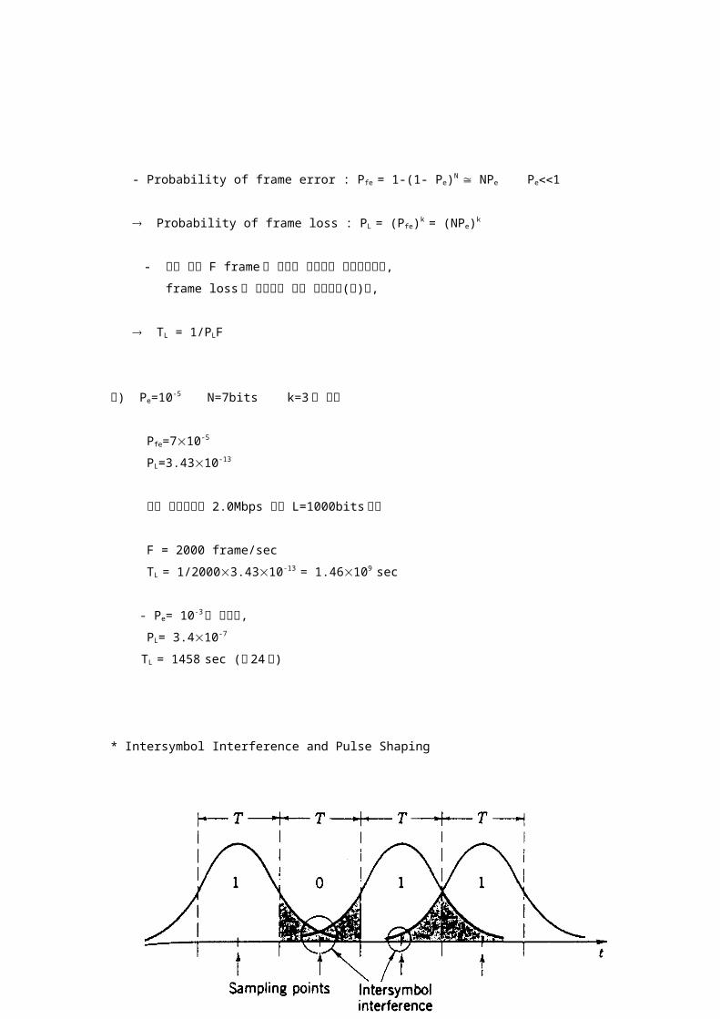
* Intersymbol Interference and Pulse Shaping
132

Intersymbol interference in digital transmission
o Intersymbol Interference : Time Domain
o Energy spill-over to adjacent channel : Frequency Domain
o sinx/x pulse 형태를 사용하면 sampling point 에서 intersymbol
interference 를 제거(최소화) 할 수 있다
133
o Intersymbol Interference 를 최소로 할 수 있는 pulse shape
- h(t) should be max at t=0
- h(t) should be zero at t=T, 2T, 3T,
- h(t) should be small at other interval
o Nyquist Filter(Ideal Lowpass Filter)
- Pulse spacing : T 1/T bits/sec
- Requird Bandwidth 1/2T Herz
- 최대 효율인 2 bits/Hz 로 전송가능
- 정밀한 bit 동기 필요
- Nyquist Filter(Ideal Lowpass Filter)는 sharp cutoff 특성
때문에 실제 구현이 불가능함.
134

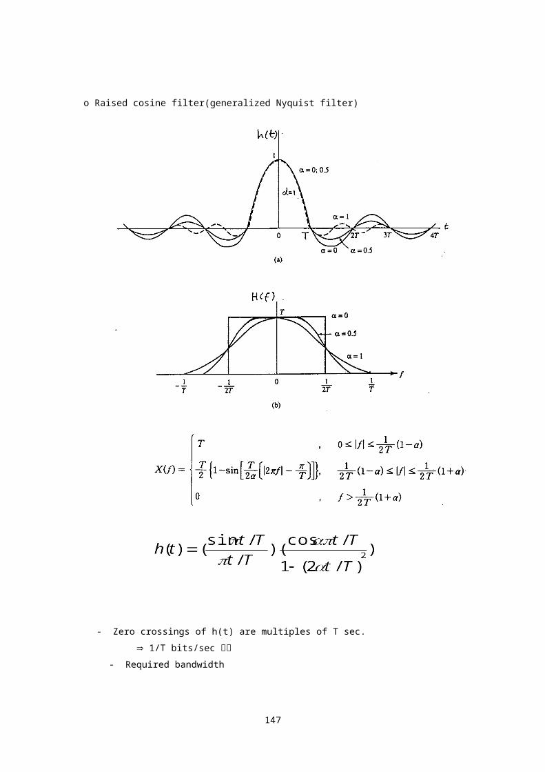
o Raised cosine filter(generalized Nyquist filter)
- Zero crossings of h(t) are multiples of T sec.
1/T bits/sec 전송
- Required bandwidth
: roll off factor
135

- 따라서 roll off factor 가 인 Raised cosine filter 사용시
o roll off factor 가 인 raised cosine filter 사용 시
=0 2 bits/Herz 송신 Nyquist Filter
=1 1 bits/Herz 송신 Raised Cosine Filter
예) 통신채널의 대역폭이 B Herz 일때 이 채널로 전송
가능한 최대 전송속도는? 단 baseband transmission 을
사용함.
최대 전송속도 =
예) 통신채널의 대역폭이 B=2.4 Kherz(전화선 등)일때 이
채널로 전송 가능한 최대 전송속도는? 단 baseband
transmission 을 사용함.
=0 1/T=2B=4800 symbol/sec
binary signaling 사용 시 : 1/T=2B=4800 bits/sec
=0.25 1/T=
=1 1/T=
136

Baseband Transmission
137
* Eye Pattern
138
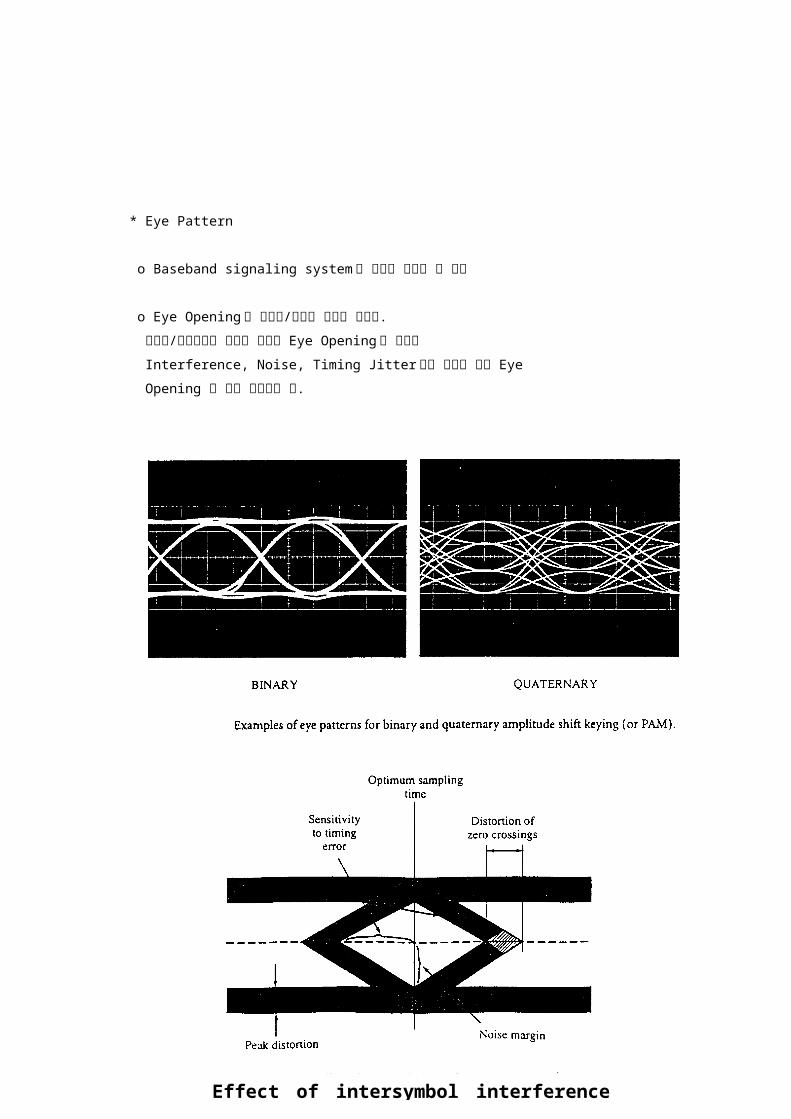
* Eye Pattern
o Baseband signaling system 의 성능을 평가할 수 있음
o Eye Opening 은 시스템/채널의 상태를 표시함.
시스템/채널상태가 양호할 때에는 Eye Opening 이 넓으나
Interference, Noise, Timing Jitter 등이 커짐에 따라 Eye
Opening 이 점차 닫혀지게 됨.
139
Effect of intersymbol interference on eye opening
o Eye Pattern 의 예
140

Digital communication
Duobinary Technique
Baseband communication
Probability of error
Error analysis of repeaters
인터넷 공학부
141

* Duobinary Technique(Partial response signaling)
y(t-kT)=xk(t-kT)+ xk-1[t-(k-1)T] xk=1
yk =xk+ xk-1 yk =0, +2 or -2
O 수신기에서 decoding
- Intersymbol interference 를 적극적으로 활용하는 방식
- 2 bits/Hz 의 효율로 전송가능
- 오류검출(error detection) 가능
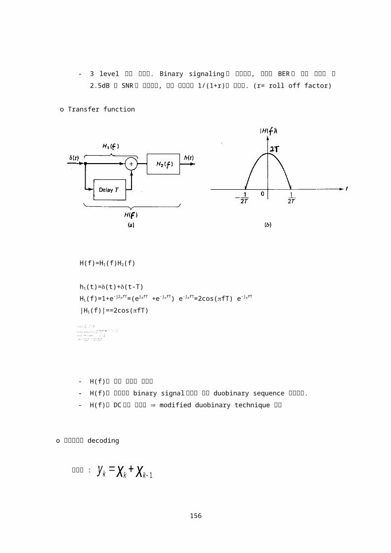
- 3 level 전송 방식임. Binary signaling 과 비교하면, 동일한 BER 을 얻기 위하여 약 2.5dB
큰 SNR 이 필요하며, 전송 대역폭은 1/(1+r)이 소요됨. (r= roll off factor)
142

o Transfer function
H(f)=H1(f)H2(f)
h1(t)=(t)+(t-T)
H1(f)=1+e-j2fT=(ejfT +e-jfT) e-jfT=2cos(fT) e-jfT
|H1(f)|==2cos(fT)
- H(f)는 구현 가능한 필터임
- H(f)를 사용하여 binary signal 로부터 바로 duobinary sequence 발생가능.
- H(f)에 DC 성분 포함됨 modified duobinary technique 사용
o 수신기에서 decoding
송신기 :
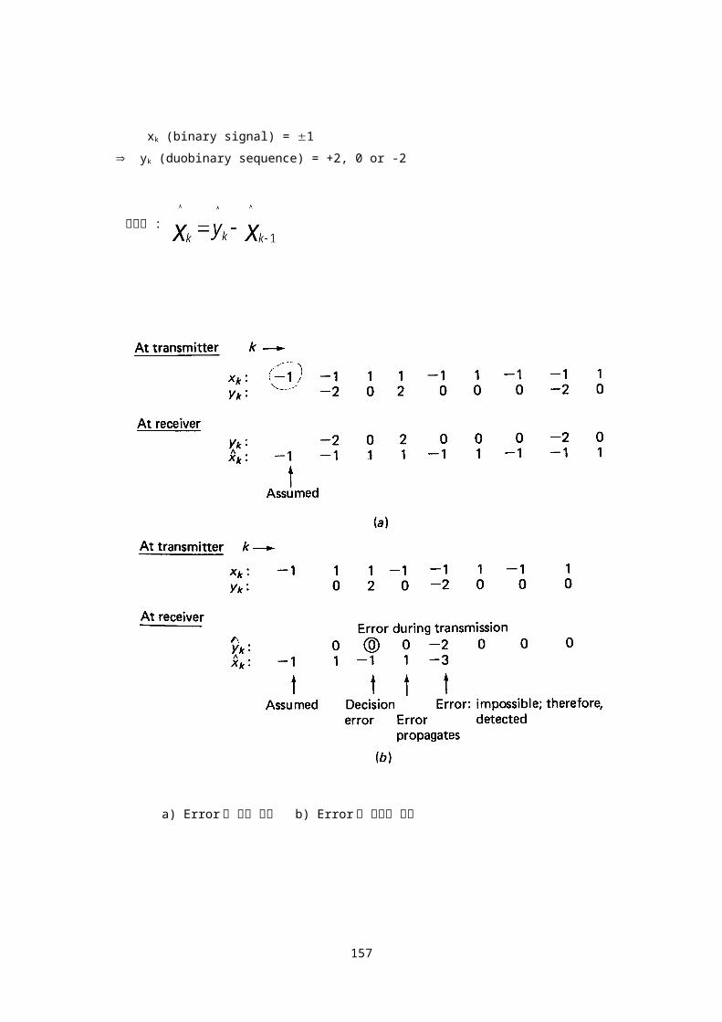
xk (binary signal) = 1
yk (duobinary sequence) = +2, 0 or -2
143
수신기 :
a) Error 가 없는 경우 b) Error 가 발생한 경우
- Precoding
144

* Modified Duobinary Technique
yk =xk- xk-2
xk= 1 yk = 0 or 2
xk=0 or 1 yk = 0 or 1
145

H(f)= H1(f) H2(f)
h1(t)=(t)+(t-2T)
H1(f)=1-e-j4fT=(ej2fT -e-j2fT) e-j2fT=2je-j2fT sin(2fT)
|H1(f)|=2|sin(2fT)|
H2(f) = T |f| 1/2T
= 0 |f| 1/2T
- sin(2fT) 필터는 구현이 용이하지 않음.
- 구현이 용이한 등가 필터 필요
o Implementation of modified duobinary technique
146
a) Basic implementation of modified duobinary technique
b) Spectral characteristic
c) Alternate implementation
H1(f) = 1-e-j4fT = (1-e-j2fT)(1+e-j2fT)
H(f) = (1-e-j2fT)2Tcos(ft)e-jfT |f| 1/2T
= 0 기타
o 수신기에서 decoding
- 송신기 :
xk = 0 or 1 yk = 0 or 1
- 수신기 :
147

a) Error 가 없는 경우 b) Error 가 발생한 경우
- Precoding
148

o 전송오류 검출(Error Detection Capabiity)
- Modified duobinary sequence(precoded)
데이터 열을 짝수번째 열과 홀수번째 열로 분리 시,
최대 level 값과 최소 level 값이 교대로 나와야 함.
(yk=1, 0, -1 최대/최소 level 값=1, -1)
홀수 열 : –1 1 0 0 –1 0 1, 짝수 열 : 1 –1 1 0 0 0
- Duobinary sequence(precoded)
최대 level 값 데이터 bit 와 최소 level 값 데이터 bit 사이
에는 홀수개의 중간 level 값 데이터가 들어있어야 하며
동일한 최대 또는 최소 level 값 bit 사이에는 짝수개의
중간 level 값 데이터가 들어있어야 함.
(yk=2, 1, 0 최대/최소 level 값=2, 0)
* Baseband Detection
o Single sample detector
o Matched filter detector
- Noise
Additive noise n(t) in communication system is assumed to be
white noise with zero mean Gaussian probability density function.
E(n) = 0, 2 : noise power
149
Gaussian probability density functionTypical oscillogram, noise voltage

o Single sample detector
Effect of noise in binary pulse transmission(baseband unipolar)
Tx Rx
for “0” : 0 V 0 V + n(t)
for “1” : A V A V + n(t)
Pe0 = Prob.(v > A/2) =
Pe1 = Prob.(v < A/2) =
Pe = P0Pe0 + P1Pe1
Probability densities in binary pulse transmission(unipolar)
150

t=(k+1/2)Tb
Single sample detector
Let
then
Hence, for the binary baseband communications using unipolar
NRZ pulses, the probability of bit error is;
where N=2 = nofm : noise power
no = noise power spectral density
fm = LPF cut-off frequency
151
low pass filterfcut off=fm
compare tothreshold
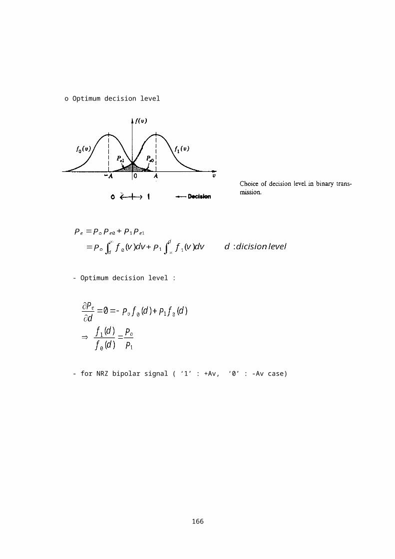
o Optimum decision level
- Optimum decision level :
- for NRZ bipolar signal ( ‘1’ : +Av, ‘0’ : -Av case)
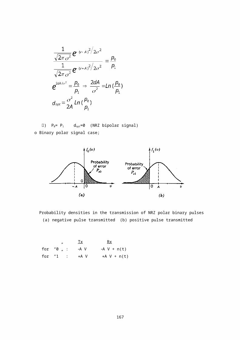
예) P0= P1 dopt=0 (NRZ bipolar signal)
152

o Binary polar signal case;
Probability densities in the transmission of NRZ polar binary pulses
(a) negative pulse transmitted (b) positive pulse transmitted
Tx Rx
for “0” : A V A V + n(t)
for “1” : A V A V + n(t)
Pe = P0Pe0 + P1Pe1
Let
then
Hence, for the binary baseband communications using bipolar
153

NRZ pulses, the probability of bit error is;
where N=2 = nofm : noise power
no = noise power spectral density
fm = LPF cut-off frequency
S=A2 : average signal power
o Remark
- for unipolar NRZ pulses, BER is ;
- for bipolar NRZ pulses, BER is ;
- Thus, to obtain same S/N, bipolar signal requires only half the
signal amplitude of the unipolar signal, or 1/4(-6dB) of the peak
power.
Error anaysis of repeaters
154

* Nongenerative Repeater
Repeater amplifiers
- Assume binary polar signal transmission.
The prob. of error at one (first) repeater is,
- After first link;
V(t) = A + n1(t)
After second link;
V(t) = A + n1(t) + n2(t)
After m link;
V(t) = A + <= Var = mn2
Y = x1 + x2 + ..... + xN
Var(Y) = y2 =
If the R.V.S. xi are independent and have same variance then,
y2 = = Nx
2
Hence, the prob. of error for nongenerative repeater is,
155
* Regenerative Repeater
- At the first repeater;
output = 오류가 발생하지 않은 경우
= 오류가 발생한 경우
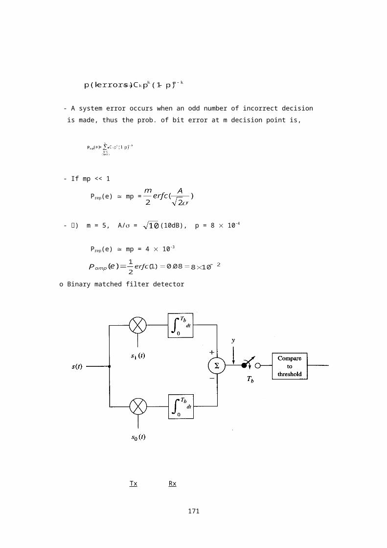
- The prob. of error of making k errors at the m decision point is,
- A system error occurs when an odd number of incorrect decision
is made, thus the prob. of bit error at m decision point is,
- If mp << 1
Prep(e) mp =
- 예) m = 5, A/ = (10dB), p = 8 10-4
Prep(e) mp = 4 10-3
o Binary matched filter detector
156
Tx Rx
for “0” : S0(t) S0(t)+n(t)
for “1” : S1(t) S1(t)+n(t)
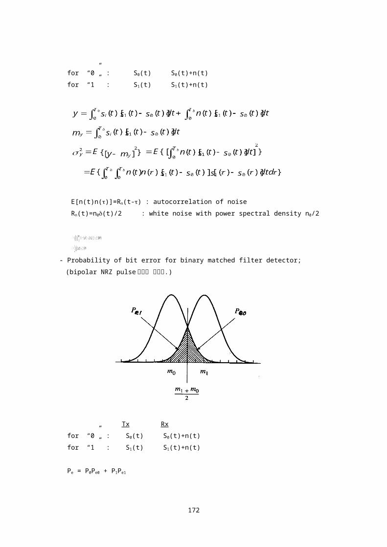
E[n(t)n()]=Rn(t-) : autocorrelation of noise
Rn(t)=n0(t)/2 : white noise with power spectral density n0/2
- Probability of bit error for binary matched filter detector;
(bipolar NRZ pulse 사용을 가정함.)
157

Tx Rx
for “0” : S0(t) S0(t)+n(t)
for “1” : S1(t) S1(t)+n(t)
Pe = P0Pe0 + P1Pe1
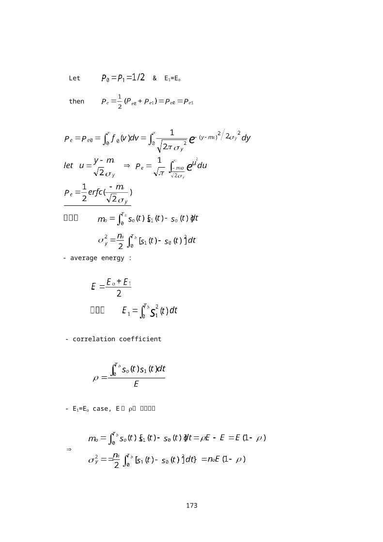
Let & E1=Eo
then
- average energy :
158

- correlation coefficient
- E1=Eo case, E 와 를 대입하면
- Probability of bit error decreases
1. average energy 증가 시
2. the correlation 감소 시
3. noise power 감소 시
- for S1(t)= So(t), = 1 case,
159

Digital communication Digital modulation
ASK
FSK
Coherent & Noncoherent detection
인터넷 공학부
160

Modulation Technique
1. Why Modulate ?
* Antenna radiation 효율
- 음성 3khz 100Km antenna 필요
- 반송파 30Mhz로 변조 10m antenna 필요
* Frequency space sharing
- FDM이 가능토록
2. Digital Binary Modulation
* Amplitude Shift Keying (ASK)
* Frequency Shift Keying (FSK)
* Phase Shift Keying (PSK)
3. Digital Multilevel Modulation
* M-ary Frequency Shift Keying (MFSK)
* M-ary Phase Shift Keying (MPSK)
* Quadrature Amplitude Modulation (QAM) * Minimum Shift Keying (MSK)
4. 복조 방식(Type of Detection)
* Coherent Detection (Synchronous Detection)
- Needs frequency and phase information of
the transmitted signal.
* Noncoherent Detection
- Envelope Detection
5. 반송파(Carrier Signal)
161

* fc(t) = A cos(2fct+)
fc large, Capacity large
Digital Binary Modulation
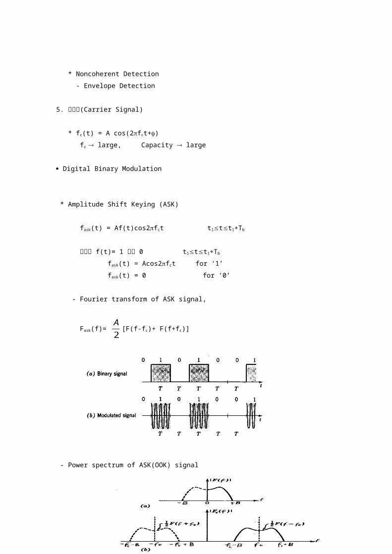
* Amplitude Shift Keying (ASK)
fask(t) = Af(t)cos2fct t1tt1+Tb
여기서 f(t)= 1 또는 0 t1tt1+Tb
fask(t) = Acos2fct for ‘1’
fask(t) = 0 for ‘0’
- Fourier transform of ASK signal,
Fask(f)= [F(f-fc)+ F(f+fc)]
- Power spectrum of ASK(OOK) signal
162

- 전송 대역폭
163
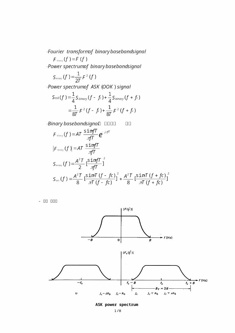
ASK power spectrum

Pulse duration = Tb sec.
Data rate(데이타 전송속도) = Rb = 1/Tb Bits/sec.
roll off factor r인 raised cosine filter로
shaping한 baseband binary signal의 대역폭은,
Rb=1/Tb bits/sec의 ASK(OOK) signal을 전송하는
데 필요한 주파수 대역폭은,
예) r=0, pulse shaping : BT=Rb herz
r=1, pulse shaping : BT=2Rb herz
Rb bits/sec의 ASK signal의 전송대역폭 :
r에 따라, Rb herz ~ 2Rb herz
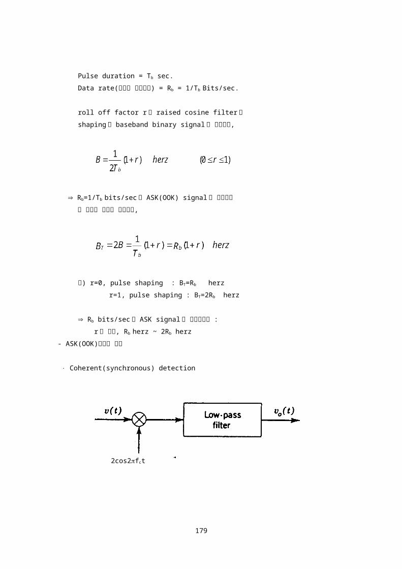
- ASK(OOK)신호의 복조
Coherent(synchronous) detection
Synchronous detection을 위해서는 수신기의 local
신호 2cos2fct와 송신기의 반송파 cos2fct의
164
2cos2fct

frequency와 phase가 정확하게 일치(동기) 해야함.
수신기에 수신된 신호,
v(t) = Af(t)cos2fct + n(t)
= [Af(t) + x(t)]cos2fct - y(t)sin2fct
여기서 n(t)=x(t)cos2fct-y(t)sin2fct
Then at the detector output,
vo(t) = Af(t) + x(t)
vo(t) = A + x(t) for ‘1’
x(t) for ‘0’
Mean noise power
Probability of error
Pe0 = Prob.(v > A/2) =
Pe1 = Prob.(v < A/2) =
Pe = P0Pe0 + P1Pe1
165
Let
then
ASK(OOK) 전송방식의 bit 오류 확률은,
where : noise power
no = noise power spectral density
B = LPF cut-off frequency
Matched Filter Detection(OOK)
Peak power SNR of the matched filter is,
The minimum probability of error is obtained
166
by replacing .
여기서
Es : high freq. signal(symbol) energy
no : noise power spectral density
Average energy per bit를 Eb로 표시하면,
Eb=(E0+E1)/2=(0+Es)/2= Es/2 (OOK 경우)
Matched filter 복조시, OOK의 bit오류 확률은,
예) Binary signal f(t)가 구형파인 경우
Noncoherent(envelope) detection
1. Noncoherent detection은 수신기와 송신기간
frequency와 phase 동기가 요구 되지않음.
167

2. OOK and FSK signals can be detected with
the envelope detector.
z(t) = s(t) + n(t)
= [Af(t) + x(t)]cos2fct - y(t)sin2fct
= r(t)cos[2fct + (t)]
여기서 f(t) = 1 (t1tt1+Tb) for ‘1’
= 0 (t1tt1+Tb) for ‘0’
- If a ‘0’ was sent,
Rayleigh :
- If a ‘1’ was sent,
Rician :
여기서 N = n0B : noise power
Probability of error
168

여기서 d : decision level
for high SNR, P0=P1=1/2, the probability of bit error for noncoherent
OOK is,
여기서 B = 1/Tb : detector bandwidth
:average energy per bit
Es : high freq. signal(symbol) energy
예) Binary signal f(t)가 구형파인 경우(OOK)
169

- 동일한 BER을 얻기위해 noncoherent detection 방식은 coherent
detection방식보다 약 1dB 정도 큰 power가 필요하나 장비 구조가
상대적으로 간단.
OOK는 noncoherent detection방식사용
* Frequency Shift Keying (FSK)
ffsk(t) = Acos[2(fc+f)t]=Acos2f1t for ‘1’
= Acos[2(fc-f)t]=Acos2f0t for ‘0’
여기서 t1tt1+Tb
f : 주파수 편이
- Power spectrum of FSK signal
FSK power spectral density
- 전송 대역폭
Pulse duration = Tb sec.
Data rate(데이터 전송속도) = Rb = 1/Tb Bits/sec.
170
cos(fc-f)t cos(fc-f)tcos(fc+f)t
roll off factor r인 raised cosine filter로
shaping한 baseband binary signal의 대역폭은,
=> Rb=1/Tb bits/sec의 FSK signal을 전송하는데
필요한 주파수 대역폭은,
여기서 f : 주파수 편이
B : baseband binary signal의 대역폭
=f/B : modulation index
예) r=1 pulse shaping 또는 구형파 전송시,
- Orthogonality
Gm(t)와 Gn(t)는 상호 Orthogonal함
Gm(t)와 Gn(t)는 Orthonomal set
- Tone spacing for orthogonal FSK signaling
171
1. 수신기에서 noncoherent detection방식 사용 시
대입 후 정리하면,
임의의 에 대하여 (g1,g0)=0 이 되는 경우는
sin2(f1-f0)T=0 & cos2(f1-f0)T=1 인 경우임.
sinx = 0 for x = n
cosx = 1 for x = 2k
n = 2k sinx=0 & cosx=1
여기서 n,k 는 정수, f1>f0
172
2(f1-f0)T=2k f1-f0=k/T
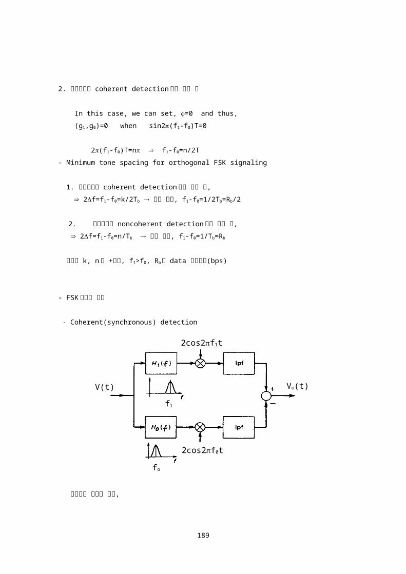
2. 수신기에서 coherent detection방식 사용 시
In this case, we can set, =0 and thus,
(g1,g0)=0 when sin2(f1-f0)T=0
2(f1-f0)T=n f1-f0=n/2T
- Minimum tone spacing for orthogonal FSK signaling
1. 수신기에서 coherent detection방식 사용 시,
2f=f1-f0=k/2Tb 최소 이격, f1-f0=1/2Tb=Rb/2
2. 수신기에서 noncoherent detection방식 사용 시,
2f=f1-f0=n/Tb 최소 이격, f1-f0=1/Tb=Rb
여기서 k, n은 +정수, f1>f0, Rb는 data 전송속도(bps)
- FSK신호의 복조
Coherent(synchronous) detection
173
2cos2f0t
2cos2f1t
Vo(t)V(t)
fo
f1

수신기에 수신된 신호,
v(t) = Acos2fit + n(t)
= [A + x(t)]cos2fit - y(t)sin2fit
Then at the detector output,
vo(t) = A + [x1(t)-x0(t)] for ‘1’
= -A + [x1(t)-x0(t)] for ‘0’
Mean noise power
Probability of error
Pe0 = Prob.(v > 0) =
Pe1 = Prob.(v < 0) =
Pe = P0Pe0 + P1Pe1
Let
then
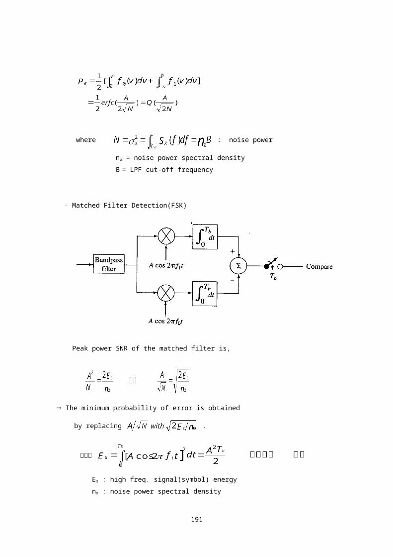
FSK 전송방식의 bit 오류 확률은,
174

where : noise power
no = noise power spectral density
B = LPF cut-off frequency
Matched Filter Detection(FSK)
Peak power SNR of the matched filter is,
The minimum probability of error is obtained
by replacing .
여기서
Es : high freq. signal(symbol) energy
no : noise power spectral density
175

Average energy per bit를 Eb로 표시하면,
Eb=(E0+E1)/2=(Es+Es)/2= Es (FSK 경우)
Matched Filter 복조시, FSK의 bit 오류 확률은,
예) 구형파 신호 :
Noncoherent(envelope) detection
gi(t) = s(t) + n(t)
= [A + x(t)]cos2fit - y(t)sin2fit
= r(t)cos[2fit + (t)]
여기서
Then at the decision point,
If a ‘1’ was sent : (r1- r0) 0
176
If a ‘0’ was sent : (r1- r0) 0
Probability of bit error
Assume P0 = P1 = 1/2, and if a ‘1’ is
transmitted. Then error occurs if the noise
causing r0 exceed the signal plus noise
envelope r1. Hence,the probability of error
for noncoherent FSK is given by,
Probability of error for noncoherent FSK
여기서 : noise power
B = 1/Tb : detector bandwidth
no : noise power spectral density
: average energy per bit
Es : high freq. signal(symbol) energy
예) Binary signal이 구형파인 경우(FSK)
177
Digital communication
BPSK
DPSK
MFSK
인터넷 공학부
178
* Binary Phase Shift Keying (BPSK)
fBpsk(t) = Af(t)cos2fct t1tt1+Tb
= Acos2fct t1tt1+Tb
= Acos(2fct+i) i = 0 or
여기서 f(t)= +1 또는 -1 t1tt1+Tb
- Power spectrum of BPSK signal
179

- Power spectrum of BPSK signal
BPSK power spectral density
- 전송 대역폭
BPSK 신호의 power spectrum이 OOK경우와 같음.
BPSK 신호의 전송대역폭은 OOK경우와 같음.
여기서 Rb=1/Tb bits/sec : 데이터 전송속도
- BPSK신호의 복조
180
T1
Rb
S(f)

Coherent(synchronous) detection
수신기에 수신된 신호,
v(t) = Acos2fct + n(t)
= [A + x(t)]cos2fct - y(t)sin2fct
여기서 n(t)=x(t)cos2fct-y(t)sin2fct
Then at the detector output,
vo(t) = A + x(t)
vo(t) = A + x(t) for ‘1’
-A + x(t) for ‘0’
Mean noise power
181
2cos2fct

Probability of error
Pe0 = Prob.(v > 0) =
Pe1 = Prob.(v < 0) =
Pe = P0Pe0 + P1Pe1
Let
then
BPSK 전송방식의 bit 오류 확률은,
where : noise power
no = noise power spectral density
B = LPF cutoff frequency
182

Effect of frequency and phase error in local
carrier
For synchronous detection,
수신 local신호 2cos2fct와 송신기반송파 Acos2fct의
frequency와 phase가 정확하게 일치(동기) 해야함.
정확하게 동기되지 않은 경우,
cos(2fc+2f)t : freq. error
cos(2fct+) : phase error
freq. error
Acos(2fct)·2cos(2fc+2f)t
= A[cos(4fc+2f)t+cos(2ft)]
Acos2ft (LPF통과후)
phase error
Acos(2fct)·2cos(2fct+)
= A[cos(4fc+)t+cos]
Acos
>/2인 경우 sign이 바뀜.
Remedy
1. pilot carrier 신호를 송신
2. 수신기에서 PLL 사용
183

- BPSK 수신기
BPSK receiver with carrier recovery circuit
1. Squaring loop
[Af(t)cos(2fct+)]2=A2/2+A2cos(4fct+2)/2
K1cos(4fct+2) (LPF통과후)
K2cos(2fct+) (2 회로 통과후)
여기서 f(t) = 1.
Squaring loop 는 초기에 (180o)만큼 phase
ambiguity 가 있음 training sequence 사용제거
2. Costas loop
184
Af(t)S(t)=Af(t)cos2fct

Matched Filter Detection(BPSK)
Peak power SNR of the matched filter is,
The minimum probability of error is obtained by replacing
.
여기서
Es : high freq. signal(symbol) energy
no : noise power spectral density
Average energy per bit를 Eb로 표시하면,
185

Eb=(E0+E1)/2=(Es+Es)/2= Es (BPSK 경우)
Matched Filter 복조시, BPSK의 bit 오류 확률은,
예) 구형파 신호 :
- Binary signaling
2 2 2
S0
186

S0 S1 d S0 S1
1 1 1
d S1 d
BPSK FSK ASK
* Differential Phase Shift Keying (DPSK)
1. 송수신기간 carrier 동기가 요구되지않음.
2. Binary signal을 differential form(예: NRZ-M, 또는 NRZ-S)으로
encoding 한 후 PSK변조.
3. 바로 전 데이터와 phase비교하여 복조.
fDpsk(t) = Acos2fct t1tt1+Tb
= Acos(2fct+i) i = 0 or
187
NRZ-S and NRZ-M

- 전송 대역폭
DPSK 신호의 power spectrum이 BPSK 경우와 같음.
DPSK 신호의 전송대역폭은 BPSK 경우와 같음.
여기서 Rb=1/Tb bits/sec : 데이터 전송속도
- DPSK신호의 복조
수신기에 수신된 신호 ,
v(t) = Acos2fct + n(t)
= [A + x(t)]cos2fct - y(t)sin2fct
Integrator output(Noise 가 없는 경우 )
o 인접한 두 bit사이에 phase가 동일한 경우
188
V(t
DPSK receiver
o 인접한 두 bit사이에 phase change가 있는 경우
o Integrator output is a bipolar baseband signal
NRZ-S format 사용 시 NRZ-L format 출력
Integrator input(Noise 포함 )
두개의 연속된 bit가 동일한 경우(동일부호)를 가정함
DPSK복조가 가능하기 위해서는 bit period가
carrier 주기의 정수배가 되어야 함. 즉,
cos2fct = cos2fctd
sin2fct = sin2fctd
Integrator output
위 관계식을 g(t)에 대입하면
189

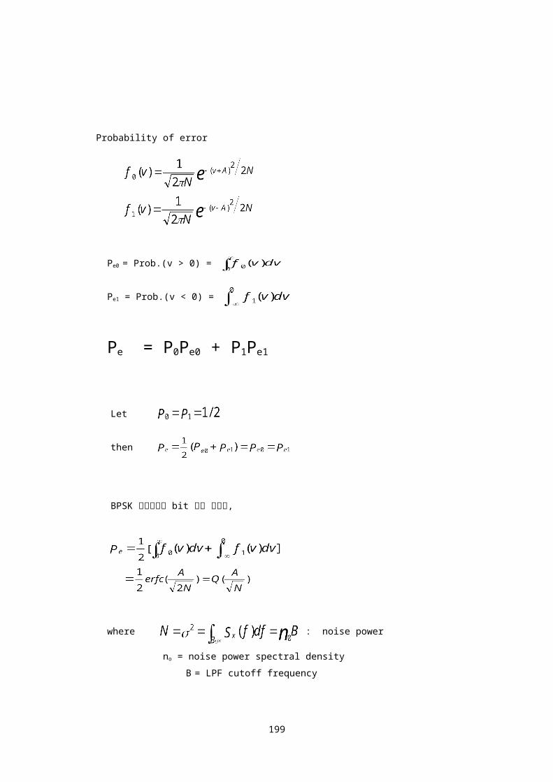
두개의 연속된 bit가 동일한 경우(동일부호)를 가정
하였으므로 Vo(Tb)<0인 경우 오류 발생함.
Pe = Prob[Vo(Tb)<0]
[Since, if P(동일부호)=P(다른부호)=1/2 then,
]
If we define,
W1 = A+ [x(t)+x(td)] W2 = [x(t)-x(td)]
W3 = [y(t)+y(td)] W4 = [y(t)-y(td)]
Then
190
- DPSK 전송방식의 bit 오류 확률은,
여기서 Eb : , average energy per bit
Es : high freq. signal(symbol) energy
no : noise power spectral density
예) Binary signal이 구형파인 경우(DPSK)
191
Performance of differentially coherent PSK

동일 BER을 얻기 위하여 Differentially coherent
PSK (DPSK)는 coherent PSK(BPSK)에 비하여 약 1dB
정도 큰 SNR이 필요함.
DPSK는 FSK, ASK와 비교시 낮은 SNR로 동일한 BER
을 얻을 수 있음
Digital Multi-level Modulation
* M-ary Frequency Shift Keying (MFSK)
* M-ary Phase Shift Keying (MPSK)
* Quadrature Amplitude Modulation (QAM)
* Minimum Shift Keying (MSK)
Multilevel Signaling
1. With Nyquist pulse shaping(roll off factor
r=0), 2B symbols/s/hz can be transmitted
over a channel with bandwidth of B herz.
2. If a symbol with M = 2K levels is used,
then 2kB bits/s/hz may be transmitted
using the same bandwidth of B herz.
3. Multilevel signals with M levels are often
called M-ary signals. Multi-phase, multi-
amplitude, and combined multi-phase
/multi-amplitude signaling schemes are
192

used to reduce the transmission bandwidth.
4. Multi-frequency schemes also can be used,
but in this case, it requires larger
bandwidth and provides improved noise
immunity as a result.
* M-ary Frequency Shift Keying (MFSK)
fMfsk(t) = Acos2fkt t1tt1+Ts
= Acos2(f0+kfs)t t1tt1+Ts
여기서 k=1,2,……M, (M=2L)
fs=인접 symbol 간 주파수 이격
Ts=symbol period
f0=m/Ts, fs=n/Ts, L,m,n 은 정수
Orthogonal MFSK signaling
k=1,2,………M
Minimum tone spacing for orthogonal MFSK signaling
193

1. 수신기에서 coherent detection 방식 사용 시,
fj-fi=m/2Ts 최소 이격, fj-fi=1/2Ts=Rs/2
2. 수신기에서 noncoherent detection 방식 사용 시,
fj-fi=n/Ts 최소 이격, fj-fi=1/Ts=Rs
여기서 i,j,m,n 은 +정수, fj>fi,
Ts 는 symbol period
Rs 는 symbol rate(symbol/sec)
fj-fi=n/Ts=nRs(최소 이격:n=1)인 경우, 두 가지
detection 방식에서 orthogonal signaling 이 됨.
- Power spectrum of MFSK signal,
- 전송 대역폭
Bit rate = Rb bits/sec.
symbol rate : Rs = Rb/log2M symbols/sec.
= Rb/L symbols/sec.
(L=log2M bits/symbol)
roll off factor r 인 raised cosine filter 로
shaping 한 baseband symbol signal 의 대역폭은,
194

따라서 Rb bits/sec 의 데이터를 orthogonal MFSK
signaling 방식으로 전송 시 필요한 주파수 대역폭은,
여기서 fs : 인접 symbol 간 주파수 이격(=Rs Hz)
B : baseband symbol signal 의 대역폭
예) r=1 pulse shaping 또는 구형파 전송 시,
- MFSK 신호의 복조
Coherent detection(matched filter detection)
수신기에 수신된 신호,
195

v(t) = Acos2fkt + n(t)
Then the matched filter outputs are,
Orthogonal MFSK 를 가정하면 Yi 는,
(sinusoidal bursts are orthogonal to each other)
Yi 는 Gaussian R.V.들이며 평균값은,
Yi 의 variance 은,
E[n(t)n()]=Rn(t-):autocorrelation of noise
Rn(t)=n0(t)/2 :white noise with power
spectral density n0/2
k 번째(yk) matched filter 에 정보신호가 들어왔을 때, 임
의의 다른 matched filter 출력(yi)이 yk 보다 클 확률은
196

여기서 symbol energy
M-ary signaling 인 경우 (m-1)개의 yi 가 yk 보다 클
수 있으므로 probability of symbol error 는,
여기서 Es=Eblog2M(or Eb=Es/log2M=Es/L), Eb : bit 에너지
M-ary orthogonal signaling 의 경우, probability of symbol error
(Pse)와 probability of bit error(Pbe)는 다음식과 같이 표시됨.
197

여기서 L=log2M bits/symbol
예)
0 0 0
0 0 1
0 1 0 송신된
0 1 1 symbol
1 0 0
1 0 1 symbol 오류발생 경우 수=2L-1=7 1 1 0 bit 오류발생 경우 수=2L-1 =4 1 1 1 여기서 M=8, L=3, (3=log28) coherent MFSK 의 probability of bit error 는,
Noncoherent(envelope) detection
gi(t) = s(t) + n(t)
= [A + x(t)]cos2fkt - y(t)sin2fkt
198
= r(t)cos[2fkt + (t)]
여기서
Then the envelope detector outputs are,
r1 : Rician pdf, r2 : Rayleigh pdf
k 번째(yk) envelope detector 에 정보신호가 들어왔을 때,
임의의 다른 envelope detector 출력(yi)이 yk 보다 클 확률,
Probability of symbol error for noncoherent MFSK
M-ary signaling 인 경우 (m-1)개의 yi가 yk 보다 클
수 있으므로 probability of symbol error 는,
M-ary orthogonal signaling 의 경우, probability of symbol error
(Pse)와 probability of bit error(Pbe)는 다음식과 같이 표시됨.
여기서 L=log2M bits/symbol
noncoherent MFSK 의 probability of bit error 는,
199

여기서 Es=Eblog2M(or Eb=Es/log2M=Es/L), Eb : bit 에너지
200

Symbol error probability for Noncoherently
detected M-ary orthogonal signaling
201

Digital communication QPSK/OQPSK
MPSK
MSK
QAM
Design Trade-offs
인터넷 공학부
202

Quadrature Phase Shift Keying(QPSK)
sQpsk(t) = Acos(2fct+n) t1tt1+Ts
= Acosncos2fct-Asinnsin2fct
여기서 n = n/2, n=0,1,2,3
rQ
01 d1 d2
A 0 0 : Acos2fct
11 00 0 1 : Acos(2fct+/2)
rI 1 0 : Acos(2fct+3/2)
1 1 : -Acos2fct
10
M-ary signaling 인 경우 M=2k개(k=log2M)의 symbol 사용,
QPSK 경우, M=4 k=2 bits/symbol
Symbol period=2bit period(Ts=2Tb)
- QPSK 변조기
203

- Power spectrum of QPSK signal,
QPSK 신호의 power spectrum 은 BPSK power spectrum
에서 bit period Tb 를 Symbol period Ts 로 대체하면 됨
- 전송 대역폭
QPSK 경우, M=4 k=2 bits/symbol
Bit rate = Rb bits/sec.
symbol rate : Rs = Rb/2 symbols/sec.
QPSK 신호의 전송대역폭은 BPSK 전송 대역폭의 1/2 임
예) r=1 pulse shaping 또는 구형파 전송 시,
204
QPSK power spectral density

- QPSK 신호의 복조
Coherent(synchronous) detection
수신기에 수신된 신호,
v(t)=s(t)+n(t)
=[Acosn+x(t)]cos2fct-[Asinn+y(t)]sin2fct
=rIcos2fct-rQsin2fct
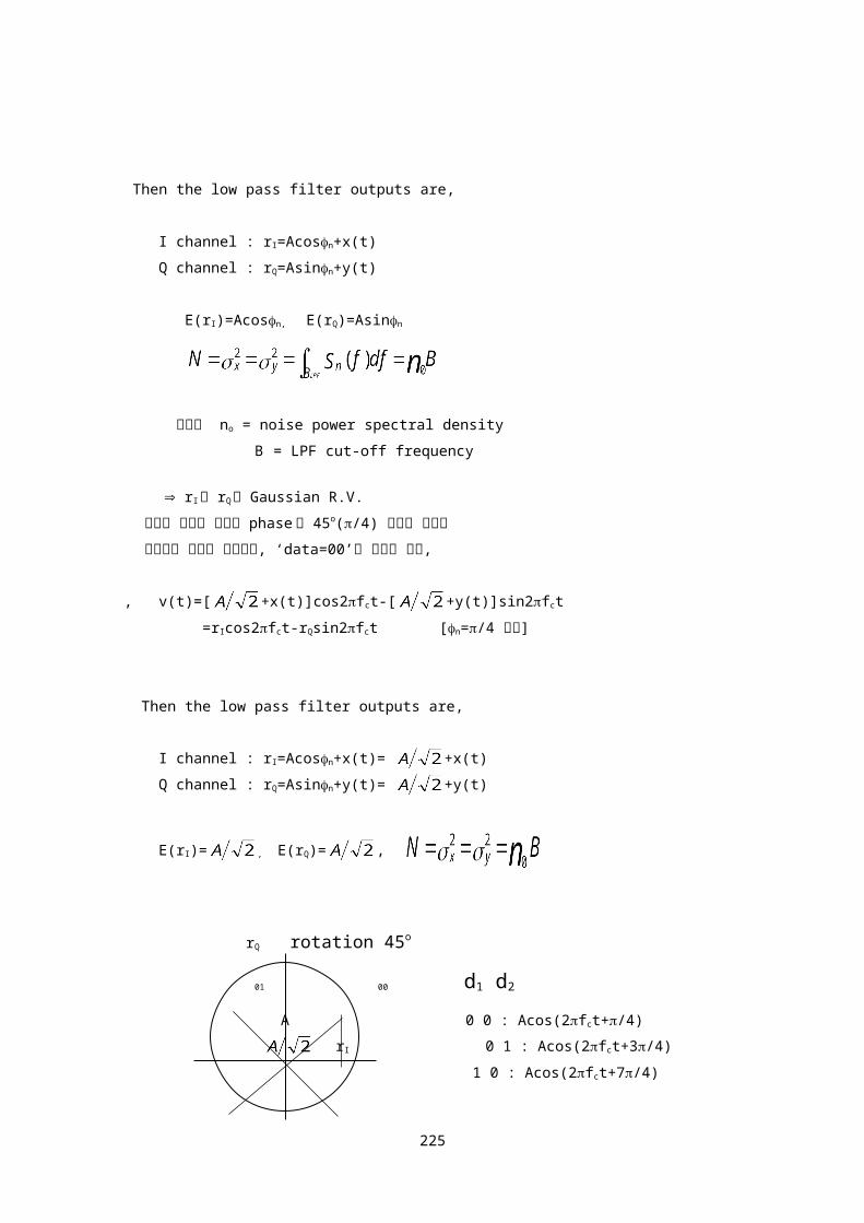
Then the low pass filter outputs are,
I channel : rI=Acosn+x(t)
Q channel : rQ=Asinn+y(t)
E(rI)=Acosn, E(rQ)=Asinn
여기서 no = noise power spectral density
B = LPF cut-off frequency
205

rI 와 rQ 는 Gaussian R.V.
해석의 편의를 위하여 phase 를 45o(/4) 회전한 신호를
사용하는 것으로 가정하면, ‘data=00’이 입력된 경우,
, v(t)=[ +x(t)]cos2fct-[ +y(t)]sin2fct
=rIcos2fct-rQsin2fct [n=/4 대입]
Then the low pass filter outputs are,
I channel : rI=Acosn+x(t)= +x(t)
Q channel : rQ=Asinn+y(t)= +y(t)
E(rI)= , E(rQ)= ,
rQ rotation 45o
01 00 d1 d2
A 0 0 : Acos(2fct+/4)
rI 0 1 : Acos(2fct+3/4)
1 0 : Acos(2fct+7/4)
11 10 1 1 : Acos(2fct+5/4)
‘data=00’ 입력된 경우 rI0 & rQ0 인 경우 오류없이 복조됨.
Psc = Proba(0rI)Proba(0rQ)
206

QPSK 전송방식의 symbol 오류 확률.
4 가지 경우의 데이터(00,01,10,11) 발생확률이 모두
동일한 것으로 가정하면,
Pse=1/4[Pse(00)+Pse(01)+ Pse(10)+Pse(11)]=Pse(00)
QPSK 전송방식의 bit 오류 확률.
QPSK 경우, M=4=2k k=2 bits/symbol
Psc=(1-Pbe)2=1-Pbe+Pbe2
Pse=1-Psc=2Pbe-Pbe22Pbe
* Remark
noise power, N=noB, NQPSK= NBPSK
QPSK : NQPSK=no(1/Ts), BPSK : NBPSK=no(1/Tb)
QPSK : 2bits/symbol Ts=2Tb BQPSK= BBPSK
Matched filter detection
Peak power SNR of the matched filter is,
207

The minimum probability of error is
obtained by replacing .
여기서
Es : high freq. signal(symbol) energy
Average energy per bit 를 Eb로 표시하면,
2Eb=Es (QPSK 경우)
Matched Filter 복조시, QPSK 의 symbol 오류 확률.
Matched Filter 복조시, QPSK 의 bit 오류 확률.
- QPSK 와 BPSK 의 bit 오류 확률은 동일.
예) 구형파 신호 :
예) A 2Ghz band radio system is required to
carry 96 PCM voice channels within 3.5Mhz
bandwidth. For a choice of 4 PSK modulation
with raised cosine filtering,
208

1. determine filter roll-off factor r.
2. determine S/N required to provide BER=10-6.
T1 = PCM 24 ch. = 1.544Mbps
T2 = PCM 96 ch. = 6.312Mbps = 4 T1
1.
1.8 = 2/(1+r) => r = 0.1
2. S = EbRb, N =noBN
S/N = EbRb/noBN=(Eb/no)(Rb/BN)
10-6 = => Eb/no = 11.7 => 10.7 dB
수신기 대역통과필터(BPF) 출력 단에서의 S/N :
(S/N)dB=(Eb/no)dB+log10(Rb/BN), BN=3.5Mhz
=10.7dB+2.6dB=13.3 dB
Eb : energy per bit
Es : energy per symbol
no : noise power spectral density
BN : 수신기 BPF 대역폭
M-ary Phase Shift Keying(MPSK)
sMpsk(t) = Acos(2fct+n) t1tt1+Ts
= Acosncos2fct-Asinnsin2fct
여기서
209

.
- MPSK : M=2k개(k=log2M)의 symbol 사용,
인접 symbol 간 Phase separation : 2/M
Symbol period=kbit period(Ts=kTb)
rQ
A rI
- Decision rule : correct decision is made if received phase is
within /M of the transmitted phase
- Matched Filter 복조시, MPSK 의 symbol 오류 확률.
- Matched Filter 복조시, MPSK 의 bit 오류 확률.
- Power spectrum of MPSK signal,
210

- 전송 대역폭
MPSK 경우, M=2k k bits/symbol
Bit rate = Rb bits/sec.
symbol rate : Rs = Rb/k symbols/sec.
MPSK 신호의 전송대역폭은 BPSK 전송 대역폭의 1/k 임
예) r=1 pulse shaping 또는 구형파 전송 시,
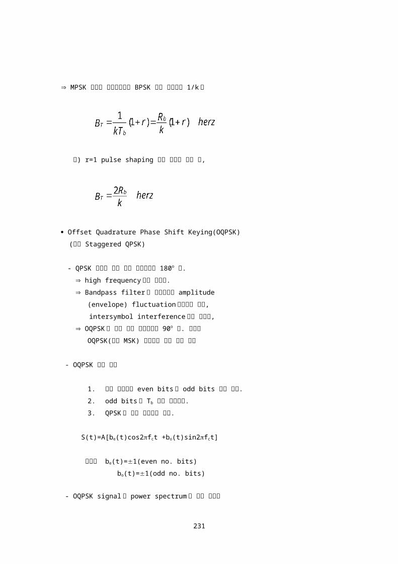
211
f-fc

Offset Quadrature Phase Shift Keying(OQPSK)
(또는 Staggered QPSK)
- QPSK 신호는 최대 순간 위상변화가 180o 임.
high frequency 성분 포함됨.
Bandpass filter 를 통과시키면 amplitude
(envelope) fluctuation 발생하게 되며,
intersymbol interference 등을 유발함,
OQPSK 는 최대 순간 위상변화가 90o 임. 따라서
OQPSK(또는 MSK) 사용하여 문제 완화 가능
- OQPSK 변조 신호
1. 입력 데이터를 even bits 와 odd bits 열로 분리.
2. odd bits 를 Tb 만큼 지연시킴.
3. QPSK 와 같은 방식으로 변조.
S(t)=A[be(t)cos2fct +bo(t)sin2fct]
여기서 be(t)=1(even no. bits)
bo(t)=1(odd no. bits)
- OQPSK signal 의 power spectrum 과 전송 대역폭
OQPSK 는 QPSK 와 마찬가지로 1/2 rate PSK 신호의
합으로 볼 수 있음.
OQPSK 의 power spectrum 과 전송 대역폭은 QPSK
와 동일함
- Probability of error
OQPSK 의 bit 오류 확률은 QPSK 와 동일함
212

213

I and Q data relationship in QPSK and OQPSK
Minimum Shift Keying(MSK)
(또는 Continuous phase FSK)
- MSK 는 OQPSK 의 특별한 경우, 즉 sinusoidal symbol weighting 처리된 OQPSK 로 볼 수
있음.
MSK has no phase discontinuity, and has a constant envelope.
The maximum phase change is 90o.
- MSK 는 CPFSK 의 특별한 경우로도 볼 수 있음.
minimum frequency separation : f2-f1=1/2Tb=Rb/2.
- MSK 변조 신호
S(t)=A[de(t)cos( )cos2fct
+do(t)sin( )sin2fct]
여기서 kTb<t<(k+1)Tb
fc = m/Tb = mRb m : 정수
de(t)=1(even no. bits)
do(t)=1(odd no. bits)
1. sinusoidal symbol weighting function : cos( )
2. f1=fc- , f2=fc+ , f2-f1= ,
214

MSK waveform
215

- MSK 변조 신호의 power spectrum
- MSK 변조신호 전송 대역폭
MSK 전송 대역폭은 QPSK 또는 OQPSK 의 1.5 배임.
그러나 sidelobe 는 QPSK 나 OQPSK 보다 훨씬 빨리 감소함.
216
(fc) fTb

- Probability of error
MSK 의 bit 오류 확률은 QPSK 또는 OQPSK 와 동일함
Coherent QPSK detection(Matched Filter)과 같은 방식
사용 시, MSK 의 bit 오류 확률.
MSK 는 Coherent FSK detection(Matched Filter)방식으로도
복조 가능함. 이 경우는 Coherent QPSK 방식 보다 3dB
(S/N) 성능이 떨어짐.
MSK 는 SNR 이 충분할 경우, Noncoherent FSK detection
방식으로도 복조 가능함.
Gaussian low-pass filtered MSK(GMSK)
입력 GMSK
데이터 변조신호
- = (2f)/Rb = (f2-f1)/Rb
- MSK 보다 mainlobe 가 협대역임. Out of band
spectrum 도 MSK 보다 빨리 감소함.
- 지상 이동통신에 많이 활용됨.
- LPF 의 3dB cut-off 주파수는 0.25Rb가 대표적인 값
으로 사용됨. bit 오류확률은 LPF 의 cut-off 주파수
에 따라 달라지나 MSK 경우에 비하여 약간 높아짐.
0.25Rb 사용 시 MSK 대비 0.74dB(S/N) 성능이 떨어짐.
Quadrature Amplitude Modulation
217
GaussianLPF
FM 변조기=0.5

Si(t)=aicos2fct+bisin2fct t1tt1+Ts
=ricos(2fct+i)
1. M=2L point QAM,
L bits/symbol 전송가능(Ts=LTb)
정해진 peak power 내에서 signal point 간 거
리가 최대가 되도록 M 개 signal point 를 배치
2.signal point 가 많아지면 거리가 짧아지므로 대부
분 오류정정 code 와 함께 사용.
- QAM 변조기
218

even Rb/2
Acos2fct
Rb
Binary Asin2fct
data Rb/2
odd
- Power spectrum of QAM signal,
QAM 은 QPSK 의 확장개념으로 볼 수 있음.
Power spectrum 형태는 QPSK 와 동일
- 전송 대역폭
M=2L point QAM 경우 L bits/symbol
Bit rate = Rb bits/sec.
symbol rate : Rs = Rb/L symbols/sec.
219
Splitter
2 to MLevel 변환기
2 to MLevel 변환기

M=2L point QAM 의 전송 대역폭.
여기서 r : roll-off factor
예) 16=24 point QAM, r=0 pulse shaping 인 경우,
- QAM 복조기
220

rectangular constellation, matched filter detection, Gray code
사용 시, M point QAM 의 bit 오류 확률
221

Design Considerations
1. 시스템 성능 (bit error rate)
Binary signaling
Coherent Detection Noncoherent Detection
Peak Power Average Power
BPSK
FSK
ASK
222

(Eb=(E0+E1)/2)
Multilevel signaling
Coherent
Detection
Noncoherent Detection
MPSK
MFSK
223

QAM
224
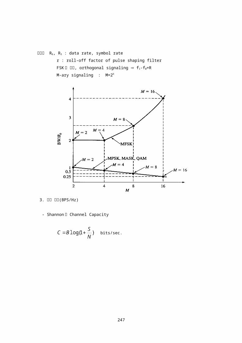
2. 소요 주파수 대역폭
단위 : Herz
소요 주파수 대역폭
(BT)
BPSK 와 비교
BPSK 1
FSK
ASK 1
MPSK1/k
MFSK
M-QAM1/k
여기서 Rb, RS : data rate, symbol rate
r : roll-off factor of pulse shaping filter
FSK 의 경우, orthogonal signaling f1-f0=R
M-ary signaling : M=2k
225

3. 전송 효율(BPS/Hz)
- Shannon 의 Channel Capacity
bits/sec.
4. 디지털 통신시스템 설계 시 중요 고려사항
- required bit transmission rate
- maximum allowable bit error rate
- maximum system bandwidth
- maximum transmitted signal power(S/N)
- maximum construction cost(complexity)
- maximum power utilization of the receiver
- maximum acquisition time of the receiver
226

Digital communication
대역확산 통신
Direct Sequence 변조
Frequency Hopping
CDMA
인터넷 공학부
227

Spread Spectrum Communication(대역확산 통신)
1. Spread Spectrum 통신은 정보를 전송하는데 필요한 최소 주파수대역보다 훨씬 넓은
대역폭을 사용함.
2. 대역확산은 확산신호를 사용하여 이루어짐. 확산신호는 정보신호와 무관함
(independent)
3. 수신기에서는 송신기와 동기된 동일한 확산신호를 사용하여 역 확산한 후
원래의 정보신호를 복조함.
Spread Spectrum 통신방식
1. Direct Sequence(DS:직접확산방식)
2. Frequency Hopping(FH:주파수 도약방식)
- Fast Frequency Hopping(FFH:고속주파수 도약)
- Slow Frequency Hopping(SFH:저속주파수 도약)
3. Time Hopping
4. Chirp
5. DS/FH Hybrid
Spread Spectrum 통신의 특징
1. Selective addressing capability
2. Code division multiple access(CDMA)가 가능.
3. Low density power spectra이므로 신호은닉 가능
4. 도청이 극히 어려움.
5. 고 정밀 거리측정(High resolution ranging)
6. 간섭신호 제거(Interference rejection)
Spread Spectrum 통신의 응용
1. 군사 통신
2. 이동 무선통신
228

Direct Sequence(DS:직접확산방식)
BPSK direct sequence spread spectrum system
송신기 : S(t)=d(t)c(t)cos2fct
수신기 : v(t)=d(t-td)c(t-td)c(t-td)cos2fct
여기서 d(t) : data (1)
c(t) : 확산 신호(pseudo noise code)
td : 송수신기간 time delay
송신기와 수신기의 확산코드 및 반송파 위상이 정확히
동기된 경우, c(t-td)c(t-td)=1
vo(t)=d(t-td)cos2fct+n(t)
229

데이터 검출기 : vo(t)2cos2fct => d(t)
- 간섭신호 또는 방해신호가 있을 경우
송신기 : S(t)=d(t)c(t)cos2fct
수신기 : v(t)=d(t-td)c(t-td)cos2fct
+J(t)cos2fjt
여기서 J(t)cos2fjt : 간섭신호 또는 방해신호
vo(t)=d(t-td)cos2fct+[J(t)c(t-td)cos2fjt]BPF
데이터 검출기 :
vo(t)2cos2fct=d(t)+[J(t)c(t)cos2(fc-fj)t]LPF
230
- Direct Sequence(DS) 변조방식의 Process Gain
*
*
*
*
*
예) data=4.8Kbps
확산신호(pseudo noise code)=10Mbps 및 50Mbps
RF BW= pseudo nose code chip rate 로 가정
10Mbps : Gp=(1.0107)/(4.8103)=2.1103=33.1dB
50Mbps : Gp=(5.0107)/(4.8103)=1.04104=40.2dB
예)
- 확산신호(pseudo noise code)
231

- Bandwidth
232

a. Half(3dB) Power : 0.88/T=0.88R
b. Noise equivalent : 1.0/T=1.0R
c. Null to Null(91% Power) : 2.0/T=2.0R
d. 99% Power
e. Bounded PSD at 35dB and 50dB
(defines attenuation outside bandwidth)
여기서
T : pulse duration
R : pulse rate(=1/T)
fc : carrier frequency
- 확산신호(pseudo noise code)
233

pseudo noise( PN ) code 는 deterministic periodic sequence 임.
그러나 unauthorized listener 에게는 noise 같이 보임.
이상적인 PN code 는 다음과 같은 3 가지 특성을 가짐.
1. 균형성(balanced property)
1주기내에 1과 0이 각각 1/2씩 포함됨. 1주기내에 포
함된 1과 0의 갯수의 차이는 한 개이내임.
2. 런 특성(run property)
런 특성은 1주기내에 연속적으로 발생하는 1과 0의 개수
로 정의되며, 1과 0 각각 run length 1인 것이 1/2,
run length 2인 것이 1/4, run length 3인 것이
1/8,…… 포함됨.
3. 자기 상관함수특성(autocorrelation property)
한 주기의 PN code와 그 PN code를 shift시킨 것을
상호 비교하면 서로 일치하는 chip갯수와 일치하지 않는
chip갯수의 차이는 한 개이내임.
* maximal length sequence는 대표적인 PN code임.
1. maximal length sequence generator는 n개의
shift register와 modulo 2 adder로 구성가능.
2. n개의 shift register로 구성한 경우 maximal
length sequence 한 주기의 길이는 2n-1임.
3. maximal length sequence는 PN code의 균형성,
런 특성, 자기 상관함수특성을 모두 만족함.
4. 한 주기의 maximal length sequence 와 그
maximal length sequence 를 shift시킨 것을
modulo 2 addition 하여 얻은 sequence는 원래의
maximal length sequence를 shift시킨 것과 같음.
234

235

Output waveform * Four stage maximal length sequence generator 출력(1 주기)
0 0 0 1 0 0 1 1 0 1 0 1 1 1 1
1. 균형성(balanced property)
1주기의 길이 : 24-1=15
Total no. of 1 : 8개
Total no. of 0 : 7개
1과 0의 갯수의 차이 : 1개
2. 런 특성(run property)
run length ones Zeros No. of chips included
1 2 2 12+12=4
2 1 1 12+12=4
3 0 1 03+13=3
4 1 0 14+04=4
Total 15
3.자기 상관함수특성(autocorrelation property)
여기서 Rc(k) : normalized autocorrelation
N : maximal length sequence 주기
Cn : chip의 부호 (1 : 11, 0-1)
k : 지연 chip수(0≦k≦N-1)
예) 0 0 0 1 0 0 1 1 0 1 0 1 1 1 1
1 0 0 0 1 0 0 1 1 0 1 0 1 1 1 a: 일치
d a a d d a d a d d d d a a a d:불일치
236

, Rc(0)=1
normalized autocorrelation of maximal length sequence
237

Frequency Hopping(FH : 주파수 도약변조)
1. 대역 확산을 DS보다 훨씬 크게 할 수 있음.
2. Near-far problem 영향이 DS보다 적음.
3. 송수신기간 동기가 DS보다 비교적 쉬움.
4. 주파수 합성기가 복잡하여짐.
5. 오류정정 부호 사용이 필요함
6. FH방식의 확산신호는 도약 주파수만을 결정함.
따라서 확산신호가 반드시 PN code일 필요는 없음.
7. FH방식의 process gain
8. FH방식은 SFH(저속도약)과 FFH(고속도약)로 구분됨.
SFH : symbol(data) ratehopping rate,
FSK, MFSK, DPSK, MSK등의 변조 사용
FFH : symbol(data) rate≤hopping rate,
MFSK변조 사용
fast freq. hopping slow freq. hopping
(BFSK, 4hops/bit) (BFSK, 3bits/hop)
238

MFSK 신호 : fMFSK(t)=Acos2(f0+kfs)t
FH/MFSK 송신기 : S(t)= Acos2(f0+fn+kfs)t
여기서 fn : n 번째 구간 도약 주파수
fo : 반송파 주파수
k=1,2,……M, (M=2L)
fs=인접 symbol 간 주파수 이격
수신기 : y(t)=[Acos2(f0+fn+kfs)t][2cos2fnt]
239

=Acos2(f0+kfs)t+n(t) => d(t)
간섭신호 또는 방해신호가 있을 경우
FH/MFSK 송신기 : S(t)= Acos2(f0+fn+kfs)t
수신기 : v(t)= Acos2(f0+fn+kfs)t+J(t)cos2fjt
y1(t)=[Acos2(f0+fn+kfs)t+J(t)cos2fjt]
[2cos2fnt]
=>Acos2(f0+kfs)t+J(t)cos2(fn-fj)t
y(t)=Acos2(f0+kfs)t+J(t)cos2(f0f)t
=> d(t)
여기서 J(t)cos2fjt : 간섭신호 또는 방해신호.
fn-fj ≤f0f(BPF 통과대역폭)인 방해신호만
BPF 통과하여 MFSK demodulator 에 나타남.
데이터 전송속도 : Rb=150 bits/sec
변조방식 : 8 FSK
symbol rate : Rs=150/log28=50 symbols/sec
hopping rate : 50 hops/sec(1 hop/symbol)
240

tone separation : fs=Rs=1/Ts=50 Hz
데이터 전송속도 : Rb=150 bits/sec
변조방식 : 8 FSK
symbol rate : Rs=150/log28=50 symbols/sec
diversity : N=4
hopping rate : 200 hops/sec(4 hops/symbol)
chip(1 hop) period : Tc=1/200 sec=5 msec
tone separation : fs=N/Ts=1/Tc=200 Hz
* FH/MFSK 에서 minimum tone separation
FFH : 1/Tc (hopping rate)
SFH : 1/TS=RS (symbol rate)
241

- FFH/MFSK 수신기
y(t)=Acos2(f0+kfs)t+J(t)cos2(f0f)t
=> d(t)
freq. hopper:고정된 반송파 주파수로 변환(dehop)
BPF & envelope detector :불요파 제거, symbol 에너지 검출
clipper : Jammer 또는 strong interference 신호 clipping
accumulator 에서 N개 symbol 축적 후, 상호 비교하여
판정함. (N hops/symbol system 가정)
- Ideal frequency hopper output spectrum
242

FH/DS Hybrid System
CDMA(Code Division Multiple Access)
243

DS 또는 FH 변조를 활용하면 CDMA가 가능함.
1. Privacy : 확산 code를 알고있는 수신기만 수신가능.
2. Jamming/Interference resistance : 방해 또는
간섭신호에 강함.
3. Flexibility : TDMA와 같이 user들간의 정밀한
timing synchronization이 요구되지 않음.
- DS-CDMA
사용자 그룹 1 송신기,
데이터 변조 : s1(t)=A1(t)cos[2fot+1(t)]
대역확산 신호 : g1(t)s1(t), [g1(t)는 spreading code]
사용자 그룹 2 송신기 : g2(t)s2(t)
사용자 그룹 N 송신기 : gN(t)sN(t)
사용자 그룹 1 수신기
수신신호 : g1(t)s1(t)+g2(t)s2(t)+……+gN(t)sN(t)
spreading code g1(t)를 곱한 결과,
desired signal :
undesired signal :
spreading code의 특성,
244

{ + }BPF
= s1(t)+I(t)+n(t)
s1(t)를 복조하면 송신된 정보신호를 검출할 수 있음.
여기서 I(t) : 잔류 interference signal
n(t) : thermal noise
Multipath Channel
245
BPSK modulation
s(t)g(t)cosot

- Multipath Channel은 건물 등으로 인한 반사 또는 굴
절등의 원인에 의하여 송수신기간 두개 이상의 전파전파
경로가 있는 경우.
- 수신기에 수신된 신호의 amplitude fluctuation 을 초래
수신기에 수신된 신호
r(t)=As(t)g(t)cos2fot+As(t-)g(t-)cos(2fot+)+n(t)
여기서
s(t):data signal
g(t):spreading code
:multipath 신호의 direct path 신호에 대한 상대적인 크기
:서로 다른 2경로간 time delay
: 0≤≤2, random phase
n(t):white Gaussian noise
spreading code의 특성,
따라서 > Tc 인 경우,
246
Direct Sequence Spread Spectrum System의 경우,
multipath signal을 제거하는 특성이 있음.
FH system의 경우 multipath signal이 수신기에 도
달하기 전에 주파수를 바꾸어 multipath signal을 회피.
RAKE receiver
multipath signal 이 있을 경우, direct path signal 에 multipath
signal 합하여 SNR 을 개선할 수 있도록 설계된 DS 수신기.
247