bath waste filter (bwf)
TRANSCRIPT
BATH WASTE FILTER (BWF)
NAMA NO PENDAFTARAN
SITI NABILAH BINTI AZIZAN 08DPB17F1119
NURUL FADLIN SYAZWANI
BINTI NORASMADI 08DPB17F1146
NUR FARZANA BINTI NAZRI 08DPB17F1158
NUR ANISA SYUHANIZ BINTI
ABDUL IZHAM 08DPB17F1231
JABATAN KEJURUTERAAN AWAM
JUNE 2019

POLITEKNIK SULTAN SALAHUDDIN ABDUL AZIZ SHAH
BATH WASTE FILTER (BWF)
NAMA NO PENDAFTARAN
SITI NABILAH BINTI AZIZAN 08DPB17F1119
NURUL FADLIN SYAZWANI
BINTI NORASMADI 08DPB17F1146
NUR FARZANA BINTI NAZRI 08DPB17F1158
NUR ANISA SYUHANIZ BINTI
ABDUL IZHAM 08DPB17F1231
Laporan ini dikemukakan kepada Jabatan Kejuruteraan Awam sebagai memenuhi
sebahagian syarat penganugerahan Diploma Kejuruteraan Awam
JABATAN KEJURUTERAAN AWAM
JUNE 2019

AKUAN KEASLIAN DAN HAK MILIK
TAJUK : BATH WASTE FILTER (BWF)
SESI : JUN 2019
1. Kami, 1. SITI NABILAH BINTI AZIZAN
2. NURUL FADLIN SYAZWANI BINTI NORASMADI
3. NUR FARZANA BINTI NAZRI
4. NUR ANISA SYUHANIZ BINTI ABDUL IZHAM
adalah pelajar tahun akhir Diploma Kejuruteraan Perkhidmatan Bangunan, Jabatan
Kejuruteraan Awam, Politeknik Sultan Salahuddin Abdul Aziz Shah, yang beralamat di
Persiaran Usahawan, Seksyen U1, 40150, Shah Alam, Selangor.
2. Kami mengakui bahawa BATH WASTE FILTER (BWF) dan harta intelek yang ada didalamnya
adalah hasil karya/ reka cipta asli kami tanpa mengambil atau meniru mana-mana harta intelek
daripada pihak lain.
3. Kami bersetuju melepaskan pemilikan harta intelek BATH WASTE FILTER (BWF) kepada
Politeknik Sultan Salahuddin Abdul Aziz Shah bagi memenuhi keperluan untuk penganugerahan
Diploma Perkhidmatan Bangunan kepada kami.
Diperbuat dan dengan sebenar-benarnya diakui
oleh yang tersebut;
di Politeknik Sultan Salahuddin Abdul Aziz Shah, pada ……………………..
Di hadapan saya,
sebagai penyelia projek pada tarikh:…………………
a) SITI NABILAH BINTI AZIZAN
(No. Kad Pengenalan: 990724-02-5306)
…………………….
(SITI NABILAH BINTI
AZIZAN)
b) NURUL FADLIN SYAZWANI BINTI
NORASMADI
(No. Kad Pengenalan: 990529-06-5548)
…………………….
(NURUL FADLIN SYZAWANI
BINTI NORASMADI)
c) NUR FARZANA BINTI NAZRI
(No. Kad Pengenalan: 990409-02-5146)
……………………
(NUR FARZANA BINTI
NAZRI)
d) NUR ANISA SYUHANIZ BINTI
ABDUL IZHAM
(No. Kad Pengenalan: 990118-06-5500)
…………………….
(NUR ANISA SYUHANIZ
BINTI ABDUL IZHAM)
SARAH AFZAN BINTI ABD KARIM
(820904-06-5696)
……………………..
(SARAH AFZAN BINTI ABD
KARIM)

TABLE OF CONTENT
BAB PERKARA MUKA SURAT
SENARAI JADUAL
SENARAI RAJAH
SENARAI SINGKATAN
i
ii-iii
iv
PENGHARGAAN
ABSTRAK
v
vi
ABSTRACT vii
PRODUCT DESCRIPTION viii
1 INTRODUCTION
1.1 INTRODUCTION 1
1.2 BACKGROUND OF THE PROJECT 1
1.3 PROBLEM STATEMENT 2
1.4 OBJECTIVE OF THE PROJECT 2
1.5 SCOPE OF THE PROJECT 2
1.6 IMPORTANCE OF THE PROJECT 2
1.7 DEFINITION/TERMS 3
1.8 SUMMARY 3
2 LITERATURE REVIEW
2.1 INTRODUCTION 4
2.2 CONCEPT/THEORY 5
2.3 OLDER REASEARCH 6 - 29
2.4 SUMMARY 30 - 31
2.5 REFERENCES 32 - 35
3 METHODOLOGY
3.1 INTRODUCTION 36
3.2 RESEARCH DESIGN 37-39
3.3 DATA COLLECTION METHODS 40-44
3.4 STUDY INSTRUMENTS 44-46
3.5 SAMPLING TECHNIQUE 47
3.6 DATA ANALYSIS METHOD 47
3.7 SUMMARY 48
4 RESULTS
4.1 INTRODUCTION 49
4.2 DEMOGRAPHIC PROFILE OF
RESPONDENTS 50
4.3 FINDINGS 51-59
5 DISCUSSION AND CONCLUSIONS
5.1 INTRODUCTION 60
5.2 DISCUSSION 60
5.3 CONCLUSION 60
5.4 PROPOSAL 61
5.5 SUMMARY 61

GANTT CHART 62-63
APPENDIX 64-67
BROCHURE 68

i
SENARAI JADUAL
NO. JADUAL TAJUK MUKA SURAT
4.2.1 Component cost 51

ii
SENARAI RAJAH
NO. RAJAH TAJUK MUKA SURAT
1 Plumbing drainage design for toilet 18
2 New plumbing drainage design for toilet 18
3 Overall drainage system design 19
4 Drainage system problem and maintain 20
5 The double-floor and the trap
installed above the second floor
20
6 Suspended type 21
7 Half-buried type 22
3.2 Methodology flow chart 37
3.4.1 i First step in producing Bath Waste Filter
(BWF)
45
3.4.1 ii Second step in producing Bath Waste
Filter (BWF)
45
3.4.1 iii Third step in producing Bath Waste Filter
(BWF)
46
3.4.1 iv Fourth step in producing Bath Waste
Filter (BWF)
46
4.2 i
Gender 50
4.2 ii Residence 50
4.3.2.1 i Number of occupants in residence 52
4.3.2.1 ii Frequently of using bathroom in a day 53
4.3.2.1 iii Did you know the existence of floor trap
in the bathroom
54
4.3.2.1 iv The way how to throw the waste at floor
trap
55

iii
4.3.2.1 v Having a problem of stagnant water in the
bathroom
56
4.3.2.1 vi Having a problem of clogged water in the
bathroom
56
4.3.2.1 vii Did you agree if have a product that can
trap the waste and ease people to clean the
waste at the bathroom
57
4.3.2.2 a Data capture at Apartment Perdana 58
4.3.2.2 b Data capture at Terrace House at TTDI 59
4.3.2.2 c Data capture at Kamsis Block Damai 59

iv
SENARAI SINGKATAN
TTDI Taman Tun Doktor Ismail
BWF Bath Waste Filter
v
PENGHARGAAN
Bersyukur ke hadrat Ilahi serta selawat ke atas junjungan besar kita iaitu Nabi
Muhammad SAW dapatlah kami menyiapkan projek akhir dengan cemerlang dalam
tempoh ynag telah ditetapkan iaitu selama 6 bulan tanpa menghadapi sebarang
masalah yang sukar diselesai sebagai syarat penganugerahan Diploma Kejuruteraan
Awam sesi Jun 2019. Sekalung penghargaan kami ucapkan kepada semua pihak yang
terlibat secara langsung mahupun tidak langsung terutamanya penyelia kami Puan
Sarah Afzan Binti Abd Karim yang telah banyak memberi segala tunjuk ajar, nasihat,
dorongan serta kritikan membina kepada kami sehinggakan kami berjaya menyiapkan
laporan projek akhir ini. Tidak lupa juga kepada rakan-rakan dan ahli keluarga yang
banyak membantu dari segi pandangan dan kewangan dalam menyiapkan tugasan
projek akhir ini. Dengan ini kami bersyukur ke hadrat Allah SWT maka siaplah
projek akhir ini. Harapan kami semoga laporan ini dapat dijadikan contoh dan
panduan kepada pihak-pihak yang berkenaan pada masa hadapan.

vi
ABSTRAK
Kebanyakkan pengguna bilik mandi mengalami masalah bilik mandi yang
bertakung kerana perangkap lantai seringkali tersumbat oleh sisa buangan (rambut,
partikel sampah kecil) yang menyebabkan laluan perangkap lantai menjadi sempit.
Keadaan akan menjadi lebih rumit apabila melibatkan rumah kediaman jenis
kondominium / apartment / flat di mana sekiranya laluan perangkap lantai tersumbat,
jadi penyelenggaraan laluan air perlu melibatkan unit rumah di bawah. Objektif
utama kajian ini ialah untuk mereka bentuk satu perangkap sampah bagi
memerangkap sisa buangan (rambut, partikel sampah kecil) yang melalui perangkap
lantai di bilik air dan mengenalpasti kos penjimatan yang boleh diperolehi dalam
menyenggara perangkap lantai di bilik air tersebut. Skop kajian ini meliputi pada
keberkesanan penyenggaraan serta kaedah soal selidik yang dilakukan bagi
memastikan perangkap sampah yang dibina mengikut kriteria yang ditetapkan iaitu
praktikal serta berkesan. Kajian ini juga merangkumi kajian literatur, penggumpulan
maklumat dari soal selidik, lawatan ke lokasi kajian, penganalisaan maklumat yang
diperolehi dan akhir sekali penulisan laporan kajian. Hasil daripada rekabentuk
tersebut, ianya dapat berfungsi untuk menjaga bilik mandi daripada bertakung.
Berdasarkan keputusan yang diperolehi, rambut dan partikel sampah kecil banyak
tersumbat di perangkap lantai. Proses pembersihan perangkap sampah ini didapati
dilakukan selepas 3 minggu atau mengikut kehendak pengguna bagi mengelakkan
berlakunya kepadatan sampah sarap. Secara keseluruhannya, perangkap sampah Bath
Waste Filter (BWF) ini berupaya memerangkap sampah dalam kuantiti yang banyak.

vii
ABSTRACT
Most bathroom users experience stagnant bathroom problems due to traps,
floors are often clogged by waste (hair, small particles of debris) that causing the
floor trap path to narrow. Things will get more complicated when it comes to
residential such as condominium/ apartment/ flat if the floor trap path is blocked, so
maintenance of the waterway should involve the house unit below. The main
objective of this study was to design a trap waste (hair, small particles of waste)
through the floor traps in the bathroom and identify the cost savings that can be
obtained by trapping the floor traps in the bathroom. The scope of this the product is
designed to female bathroom in Blok Damai (KAMSIS), Female house at Apartment
Perdana and male house at terrace house TTDI Jaya. The study also includes
literature reviews, information gathering from investigators, visits to study sites,
analysis of information obtained and finally the writing of the research report. As a
result of the design, it works to keep the bathroom from stagnating. Based on the
results obtained, the hair and particles of small waste were clogged in the trap. This
process of cleaning up the waste trap is done after 3 weeks or according to the user's
wishes. In general, this Bath Waste Filter (BWF) can trap large quantities of waste.
Keywords — Bathroom, Floor trap, Waste, Residential, Questionnaire, Literature
Reviews

viii
PRODUCT DESCRIPTION
A Bath Waste Filter is a plumbing fixture that is installed in the floor of a
structure, mainly designed to remove any standing water near it. They are usually
round but can also rectangular or square. They usually range from 2 to 12 inches (5.1
to 30.5 cm); most are 4 inches (10cm) in diameter. The size of these Bath Waste
Filter is 180mm height x 68mm diameter. They have gratings that are made of metal
or plastic. The material that we are using for this product is stainless steel and
stainless-steel floor grating.

1
CHAPTER 1
INTRODUCTION
1.1 INTRODUCTION
When the floor trap is clogged, the water will be slow to drain directly into the
drain pipe. The water flow will take a while longer than usual. This stuck water
problem will produce an unpleasant odour. This small problem can make us face the
bigger problem of clogged water drainage. These problems need to be addressed
immediately otherwise, you may be faced with other problems such as breaking the
pipe or dealing with a bathroom that cannot function properly.
1.2 BACKGROUND OF THE PROJECT
Most toilet users are currently experiencing stagnant bathroom problems
because floor traps are often clogged by waste (hair, dust, small waste particles)
causing the floor trap path to be narrow. This will be more complicated when it
involves condominium / apartment / flat type dwelling where the floor trap is block,
so the waterway maintenance should involve the housing unit below.
Therefore, through our discussions and observations we have an idea of
creating this innovative product in order to help toilet users to carry out floor trash
cleaning work easily. This is because toilet users can reduce the workforce because of
its easy to wash Bath Waste Filter (BWF).

2
1.3 PROBLEM STATEMENT
Many wastes are clogged in the floor trap pipes that cause stagnant and dirty
bathroom floors, which cause difficulties for the users to wash dirt thrown into the
floor traps. Most users simply leave or remove dirt or trash into the floor traps.
1.4 OBJECTIVE OF THE PROJECT
We decided to design a waste trap, which works to trap waste through the
floor trap in the bathroom and identify the cost savings that can be obtained in
maintaining the floor trap in the bathroom.
1.5 SCOPE OF THE PROJECT
This product is designed to female bathroom in Blok Damai (KAMSIS),
Female house at Apartment Perdana and male house at terrace house TTDI Jaya.
1.6 IMPORTANCE OF THE PROJECT
This product is important and useful to all bathroom users in the to facilitate
the maintenance of pipes to the bathroom users. This can reduce the problem of
stagnant and clogged flooring that often occurs and keep clean in the bathroom so that
no health problems occur to the dorm users. This also creates a clean bathroom
atmosphere.

3
1.7 DEFINITION/TERMS
Floor trap – A plumbing fixture that is installed in the floor of a structure, mainly
designed to remove any standing water near it.
Clogged – Blocked with an accumulation of wet matter
Odour – A distinctive smell
Drain – Cause the water or other liquid to run out
Stagnant – Having no flow and often having an unpleasant smell as a consequence
Waterway – Route for travel by water
Dwelling – Place of residence
Workforce – The people engaged in or available for work
Dormitory – A large bedroom for several people in an institution
1.8 SUMMARY
What we can summarize in this project is that we have acquired a lot of
knowledge about clogged floor trap, so in this project we have done the result of our
research and surveys. It is important for a project to conduct research and surveys
before starting the project. This is to know whether the project is being implemented
to benefit the users of the toilets.

4
CHAPTER 2
LITERATURE REVIEW
2.1 INTRODUCTION
Literature research is a study based on true theories and applies in areas
related to research such as journals, articles, books and newspaper studies. Therefore,
in this chapter several theories related to this study such as floor trap system. When
the floor trap is clogged, the water will be slow to drain directly into the drainpipe.
The water flow will take a while longer than usual. This stuck water problem will
produce an unpleasant odour. This small problem can actually make us face the
bigger problem of clogged water drainage. These problems need to be addressed
immediately otherwise, you may be faced with other problems such as breaking the
pipe or dealing with a bathroom that cannot function properly.
Producing a literature review may also be part of graduate and post-graduate
student work, including in the preparation of a thesis, dissertation, or a journal article.
Literature reviews are also common in a research proposal or prospectus (the
document that is approved before a student formally begins a dissertation or thesis).

5
ca2.2 CONCEPT/THEORY
Traps are an important component of a plumbing system. They prevent
ingress of foul air, insects and vermin from the sewers into the building and resist the
spread of disease. Traps are constructed, so that they retain a body of water, which
acts as a water seal. Traps should be of the self-cleansing type. They should generate
enough velocity from the available flow to have a self-cleansing effect, a smooth
finish and a full uniform bore. Foul gasses produced in the sewers, drains, waste pipes
may cause a nuisance by entering in houses through house-connecting pipes if some
suitable devices do not check their passage. The appurtenances, which are used to
stop entering of foul gasses inside the houses, are known as traps. Floor is provided to
prevent the foul gasses entering into the building by providing the water seal.
Minimum 50 mm depth of water seal should be provided. Whether waste water is
flowing or not, floor trap prevents the foul gases (bad smells) to enter in to the
building. To collect waste water from the bathroom, wash area, washbasin, kitchen
sinks etc., floor trap is provided into the floor. Floor traps are available in PVC,
UPVC and CI. They are without vent pipe, but removable grating is provided at the
top of traps. Floor traps come in a variety of shapes, sizes and outlet conditions. Many
do not have a water seal at all and have a non-uniform and rough bore. Floor traps are
a source of major leakages due to their poor design, casting and poor quality. It is
prevented by using only deep seal P traps with multi-inlet fitting/traps with
connections from washbasins and other fitting to provide a positive joint. Traps
installed in the areas not in normal use may lose their water seal due to evaporation.

6
Provision must be made to renew the seal by adding water periodically and this can
be done by connecting a waste appliance to the trap (e.g. a washbasin, etc.).
Replenishment is also achieved by installing a sophisticated water supply valve with a
back-flow prevention device that is connected to the trap. Care has to be taken to
prevent installation of traps that are exposed to freezing conditions. The length of
floor trap is 310 mm, with minimum 80 mm diameter at the inlet end, 30 mm
diameter near outlet end and 73 mm diameter outside the outlet of floor trap. In
addition, 95 mm grating size provided at the top of floor trap with 8 mm diameter
holes.
2.3 PREVIOUS REASEARCH
The study conducted by Reuben Saltzman (2018) is related to floor traps. The
related thing is the smell of the trap. In cases where this unpleasant smell is, often the
problem can be attributed to what is caused by user abuse, but in many cases the
smell is due to the lack of trap seals in the floor trap. We all know that public utilities
are not always well maintained, but with proper maintenance and primary use of
traps, waterways and other floors need not be the source of unfair and unpleasant
conditions. The main purpose of the trap is to eliminate the possibility of exhaust gas
from entering the space or building. The water seal, or seal trap, effectively resolves it
by creating a barrier between two to four inches of water that prevents the sewer gas
from entering the room. Secondary benefits are that it prevents the access of pests to
trenches, as well as access to buildings through equipment by the sewer system. Traps
on the floor drain that are not connected to water supply resistance will tend to
evaporate. Other traps that are not used regularly or installed in too dry areas will also
lose their seals with easy evaporation. The result of this loss enables the health
hazards of life. Vikas Kamble and Dr. G. A. Hinge (2017) conducted a study to

7
determine alternative economics for bottle traps. Bottle trap is an essential element in
sanitary piping system. It is installed under a dishwasher or kitchen sink to remove
the inclusion of coarse waste material into the drainage system and causes the
incidence of rotten gas from the drain into the house. The objective of this research is
to design innovative, efficient and economical hydraulic bottle traps to overcome the
problem of leakage of trap seals due to evaporation to prevent pipe obstruction
between floor traps in the bathroom. It traps the smell of odours, gases and pests that
can cause harm to our health. The waste water flows from the washbasin to the bottle
trap, forces the existing water in it to drain out into the drain, and replaced by the
existing water. Therefore, the seal trap always remains with a certain amount of
water. Bottle traps can be cleaned easily, simply by opening the bottom of the main
body and washing. Then screw the bottom back into place. Bottle traps can be found
on the market in various materials such as chromium coated, steel, copper, PVC and
so on. Bottle trap should have enough water seal all the time. It must be non-
absorbent material. The internal and external surfaces of the bottle trap should be
seamlessly completed so that the dirt and others are not attached to it. Bottle traps are
suitable for all types of piping systems such as single pipe system, double pipe
system, single system & one stack semi-ventilation system. It is preferred because it
has a natural depth of 15mm in its shape. Evaporation test is carried out to check
whether new designed bottle traps are effective against existing old bottle traps in
terms of loss of trap seal due to evaporation. For smooth water flows through the
bottle trap without many obstacles caused by dirt, should wash and rinse the bottle
trap after at least 15 days. Therefore, an efficient hydraulic bottle trap model is made
to overcome the problem of losing the seal trap due to evaporation & to prevent the
choke of the pipe. The discharge after every 7 days interval shows a certain amount of
8
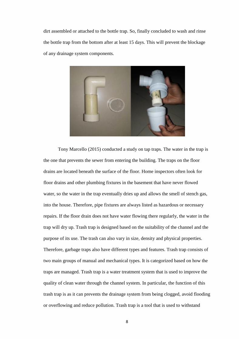
dirt assembled or attached to the bottle trap. So, finally concluded to wash and rinse
the bottle trap from the bottom after at least 15 days. This will prevent the blockage
of any drainage system components.
Tony Marcello (2015) conducted a study on tap traps. The water in the trap is
the one that prevents the sewer from entering the building. The traps on the floor
drains are located beneath the surface of the floor. Home inspectors often look for
floor drains and other plumbing fixtures in the basement that have never flowed
water, so the water in the trap eventually dries up and allows the smell of stench gas,
into the house. Therefore, pipe fixtures are always listed as hazardous or necessary
repairs. If the floor drain does not have water flowing there regularly, the water in the
trap will dry up. Trash trap is designed based on the suitability of the channel and the
purpose of its use. The trash can also vary in size, density and physical properties.
Therefore, garbage traps also have different types and features. Trash trap consists of
two main groups of manual and mechanical types. It is categorized based on how the
traps are managed. Trash trap is a water treatment system that is used to improve the
quality of clean water through the channel system. In particular, the function of this
trash trap is as it can prevents the drainage system from being clogged, avoid flooding
or overflowing and reduce pollution. Trash trap is a tool that is used to withstand

9
large waste from polluting the channel system. In general, garbage traps will contain
large waste materials. Waste materials that are too small such as bacteria cannot be
detained by trash. However, indirectly some of these substances will be stacked
together with large sized waste and this will prevent it from continuing to flow. There
are several criteria for designing a garbage trap system. The purpose of this criterion
is to get maximum effect on the effectiveness of this trash trap system. Among the
criteria required are areas with small and slow flow rates require a small-scale
garbage structure compared to areas with large flow rates. Two water conditions need
to be emphasized in the design of trash trap i.e. normal and critical condition. Normal
condition is the condition where the water will flow to normal flow while the critical
condition is the water flow condition when it reaches maximum speed. Flowing water
in low flow does not carry waste capacity and vice versa. Typically, water will carry
waste capacity after the rainy season. Each garbage trap is designed in critical water
conditions to ensure that the traps are capable of accommodating the maximum load.
Next is maintenance of traps built is necessary so that it can function properly.
Therefore, during the design process, the maintenance aspects of the trap should be
considered whether it is convenient and secure to be maintained. Maintenance work
for small size garbage traps may be easier than maintenance work for large-scale
traps. In addition, estimates of waste quantities are needed to design waste traps so
that traps can accommodate the quantity of waste that will come in. The built-in traps
are considered to be well functioned if the quantity of waste collected is large and
does not prevent the flow of water. Marek Telejko and Dorota Koruba (2019) do
research about Microclimate in Bathrooms of Multi-Family Buildings and the
analyses of the obtained test results clearly showed that in all the bathrooms under
study, the variability amplitude of the measured microclimate parameters had the

10
same character. On the days when the bathrooms were used, the RH level fluctuated
continually, with an upward trend of this parameter observed in the daytime. At night,
the relative humidity decreased gradually to reach the minimum values in the early
morning hours. During bathing, taking a shower or drying the laundry in the
bathrooms, the level of relative humidity increased rapidly to the maximum values,
and then began to drop to the initial values. The time needed to arrive at the initial
value depended on the type of activity. The longest time was recorded during laundry
drying, while the shortest time was observed in the case of taking a shower.
Lee Clifton (2011) state the principle of circuit venting is that the flow of
drainage never exceeds a half-full flow condition. The air for venting the fixtures
circulates in the top half of the horizontal branch drainpipe. The flow velocity in the
horizontal branch is slow and non-turbulent, thereby preventing pressure differentials
from affecting the connecting fixtures. The circuit-vented fixtures must connect to the
circuit-vented branch in the horizontal plane to limit the amount of turbulence created
by fixture discharge. The circuit venting method is similar to wet venting except that
it allows you to combine eight fixtures on a single floor, not limited to two-bathroom
groups. However, it might be easier to explain by examining how circuit venting
differs from wet venting. The fixture drains shall connect horizontally to the
horizontal branch being circuit vented. Again, the fixture drains are limited in length.
Because circuit venting is only to be used on horizontal applications, as opposed to
wet venting, which can be used in both horizontal and vertical installations, the
maximum slope for a circuit vent is one unit in 12 units horizontally, or an 8 percent
slope. The entire length of the circuit vent portion of the horizontal branch shall be
sized for the total drainage discharge to the branch there is not a unique sizing table
for circuit venting as there is for wet venting or common venting. The circuit vent

11
connection must be located between the two uppermost fixture drains and shall
connect to the horizontal branch. It cannot serve as a drain for other fixtures; it is
truly a dry vent. Where a circuit vent consists of four or more water closets and
discharges into a drainage stack that also receives the discharge of upper horizontal
branches, a relief vent shall be connected to the horizontal branch ahead of the
connection to the drainage stack and after the downstream fixture drain of the circuit
vent. Additional fixture drains may be connected with the circuit vented branch, but
they need to be vented by means other than the circuit vent. Also, the fixture unit
values would be added to the total fixture unit discharge into the horizontal branch.
Such fixtures must be located on the same floor as the circuit vent to which they
connect. Where the relief vent receives the discharge of other fixtures, the maximum
discharge allowed is drainage fixture units.

12
Floor drain trap and strainer. A floor drain shall be considered a plumbing
fixture and shall be provided with a trap seal and are movable strainer. The open area
of the strainer shall be at least equal to the cross-section area of the drain line to
which it connects. Basement floor drains or floor drains installed in floors which are
laid directly on the ground shall be provided with either an integral trap constructed
with a spigot outlet or a "P" trap of cast iron or other approved materials compatible
with the drainage pipe with a spigot outlet and provisions for a caulked connection to
the drain body. A vacuum breaker shall be installed on the water supply to flush rim
floor drains. Provision for evaporation. Where floor drains are subject to evaporation,
they shall be of the deep seal type, with a minimum water seal of three inches and
may be provided with a water supply through an air gap, from a plumbing fixture,
automatic priming device, or other approved means, to maintain the minimum water
seal. Venting of floor drains. Floor drain fixture branches that are less than 25 feet in
length and connect to a vented Mainor branch do not require an individual vent. The
following shall be vented in accordance with parts floor drains receiving liquid waste
flows that could siphon the trap seal; trench drains and floor sinks used as a receptor;
and floor drains used for shower drains, recessed slop, or similar receptors. Garage
and parking area floor drains. Floor area drains in open parking areas, including open
areas of parking ramps, must discharge to the storm sewer if available. Floor drains in
parking areas which are enclosed, and floor drains in areas open or enclosed which
are used for maintenance or as a vehicle wash bay, must discharge to the sanitary
sewer if a municipal sewer is available. Oil and flammable liquid separators must be
provided if required by part. S.C.Chung, Cheng-Li Cheng, Wan-Ju Liao and S.Y.
Chen (2012) According to the existing research point out the bathtub. In order to
assure the performance of the bathtub with full water and bubble to test drainage load

13
in drain. The result depth and the bubble has not back-flow. Besides, the trap
installation will use a test tower as well as the performance of the new style trap
depletion by centralizes water supply design. Besides, this device filter impurities
which can help us maintain drainage system. According to the existing research point
out, the max flow rate of sanitary equipment is order to assure the performance of the
new style trap, we use all water and bubble to test the performance of trap seal result
shows that the new style trap has the steady blew has not back-flow in low-rise
building the installation and cleaning is more easily. In the future, this research well
as an existing building (around 40-meters high) of the new style trap in high-rise
building. Besides, this device drainage system more, the max flow rate of sanitary
equipment is we used the seal when full steady seal water to confirm. The major
function of the building drainage system is to ensure proper operation and to keep a
clean and health interior space for human‘s life. Therefore, there usually exists an
interior health problem from trap seal depletion in general building Trap in drainage
systems acts as an integral part of a hygiene system in high-rise residential building
and provide an essential component in order to minimize the possible infection risk
due to the transmission of contaminants from the drainage system. Generally, a drain
trap is constructed with a minimum depth of 50mm seal water. Inappropriate design
of the drainage system within existing buildings can cause some sanitary problems
including air transient caused by discharges in the drainage stack and trap seal
depletion. Building drainage system is one of the most essential facilities in building
service engineering. The importance of building drainage system, which is a humble
but very substantial issue, must not be ignored. However, Inappropriate design of the
drainage system within existing buildings can result in some sanitary problems
including air transient caused by discharges in the drainage stack and trap seal

14
depletion. Therefore, the fundamental requirement of a building drainage system is to
carry away sanitary appliance drainage and preventing foul odours into the habitable
space from drainage network, which is important for the healthiness and comfort of
living environment. Trap seal water in a drainage system acts as an integral part of a
hygiene system in existing residential buildings and provides an essential component
in order to minimize the possible infection risk due to the transmission of
contaminants and to safeguard occupied space from stench and vermin from the
drainage network. Therefore, the building Technical regulations require that all
sanitary equipment must install the trap. Sakaue K, Fujimura K (2017) Seal water in
trap plays a crucial role in preventing foul-smelling toxic gas in drainage pipes from
entering indoors. Induced siphonage is the most important of the phenomena
associated with seal break and seal loss. This phenomenon occurs when seal water
level changes rapidly in response to air pressure fluctuations in drain and gets lost.
Though there have been several studies on numeric analyses and motion equations of
seal water fluctuation, none of them addressed the issue of seal water fluctuation
analysis in response to air pressure fluctuation in drain. Water is used in several ways
in buildings. Its main use involves appliances for water usage such as sanitary
fixtures. Water, together with wastes, is discharged through drainage pipe into the
sewer or septic tanks. The drainage pipe is usually filled with foul-smelling toxic
drainage gas and if such gas enters indoors through drain outlets of sanitary fixture, it
may contaminate air and cause health damage. In order to prevent this from
happening, fixture drainage pipes are equipped with traps, which contain seal water.
Seal water plays an important role to stop drainage gas from entering the room.
However, seal water may be lost for many reasons leading to a condition called seal
break. Induced siphonage is one of the most important seal break phenomena. In

15
induced siphonage, air pressure inside drainage pipe fluctuates when discharge is
made, and seal water also starts to fluctuate in response to pressure fluctuation
precipitating seal loss and seal break. To prevent seal break due to this phenomenon,
various precautions such as an addition of vent pipes and the use of appropriate
diameter pips are stipulated in the design method. The design method is based on a
proportional relation that regards the causal relationship of discharge flow rate and air
pressure fluctuations to seal loss as a static phenomenon. Floor drains can mix many
sources of waste, including wash water, used oil, chemicals, and sediments into a
single difficult-to-manage semi-liquid stream. Many floor drain systems include
trenches, also known as a sediment trap, and use an oil/water separator, also known as
a flammable trap, to segregate these wastes. Dewatering it into your floor drain
system and then disposing of the solids as an industrial solid waste. Do not dewater
sludge on the ground. Do not use sludge as fill on your site or spread it on the ground.
If managing it as a solid waste, place it into your solid waste collection container.
Daniel W.T. Chan and T.C. Liu, Eric S.W. Wong (2003) Floor traps in the bathrooms
and kitchens are short falls in keeping them filled up because people now only mop
floors for cleaning rather than wet it. More often, floor traps are left dry when the
occupants take a week-long vacation. It reduces the risk of contaminated air flow
from drainage stacks into indoor spaces if the floor drains can hold water for a longer
drying period without increasing the currently adopted size of the drain in practice.
This paper describes a new design of floor traps which increases the drying period.
This paper also describes the design of a test rig which facilitates the test of floor
traps for its drying up performance. Buildings absorb heat and convent to floor slab
and wall. When air-conditioning adjusts cooler temperature inside the flat, it causes
high temperature difference inside and outside the building. Floor traps being heated

16
outside have a higher evaporation rate and are easy to get dry. Many people aware
about the height of water seal which is decreased by excess air pressure inside the
drainage stack. The deep-water seal is recognized as 70 mm and the minimum is
50mm. However, many people ignore floor trap which can be dried because of
evaporation. Smart trap is a bell type floor trap. The most significant difference with
the above mentioned one is that it has larger buffer space to recover the loss of
evaporation. Safety of floor trap not only depends on the height of water seal. It
considers the contact surface of water to atmosphere. An innovated design of minor
consumed trap. When the floor traps are placed outdoor, they suffer higher wind
speed at surface of inlet. Temperature at the inlet is higher than the surface of water
seal. Good design of floor traps benefits the health of our living environment. Smart
trap provides a new concept of 2 tier water seals. Two water seals are not standalone
and have different sizes. Front water seal contacts the outside atmosphere and suffer
from various conditions (e.g. wind speed, temperature difference). The back-water
seal is larger than the front so that it can back up the loss in the front water seal. A
new concern for water trap is water retention period apart from the height of water
seal. Maintaining a trap seal can be accomplished by periodic automatic
replenishment of the water in a trap. Depending upon the floor drain size and location
manual replenishment is allowed only in limited residential single-family
applications. Consider the manual replenishment is not considered acceptable where
floor drain traps are inaccessible for manual replenishment (residential applications
only) after the installation of equipment or appliances.
Investigation and case study of floor trap:
• In recent years, due to the improvement of building technology and upgrade quality
of the life, the function of building not only provide a shelter for external climate but

17
also must satisfy all demands for daily life. As we know, the construction needs to
combine with the equipment system effectively in the building which can offer the
convenience and comfort. Therefore, this research is focused on the new style trap
developing and confirms the performance of this new style trap through investigation
and experiment. To compares the drainage performance between the different kinds
of the trap.
According to investigate result point out, the new style trap has been used in
new buildings since 2006. Designer must take into account overall drainage system
design for the new style seal trap in design stages. So, the new style tarp mostly used
in new buildings which cases is no more than 10 years and concentrated.
(1)S.C.Chung, (2) C.L. Cheng, Dr. (3) W.J.Liao, Dr (4) S.Y. Chen, Mr. (2012)
The floor trap:
• A debris trap for a floor drain includes a rim defining an outer diameter, an inner
diameter, and a radial centre. A plurality of prongs is integrally formed with the rim
and spaced along at least part of the inner diameter. At least some of the prongs are
arranged to extend order an inlet of a drain body and have approximal portion
connected to the rim and extend ingradilly inward from the rim, and a fredistal
portion that is only upwardly curved from the proximal portion toward the radial
centre of the rim.
Lawrence G. Meyers (2018)
Trap device and piping system:
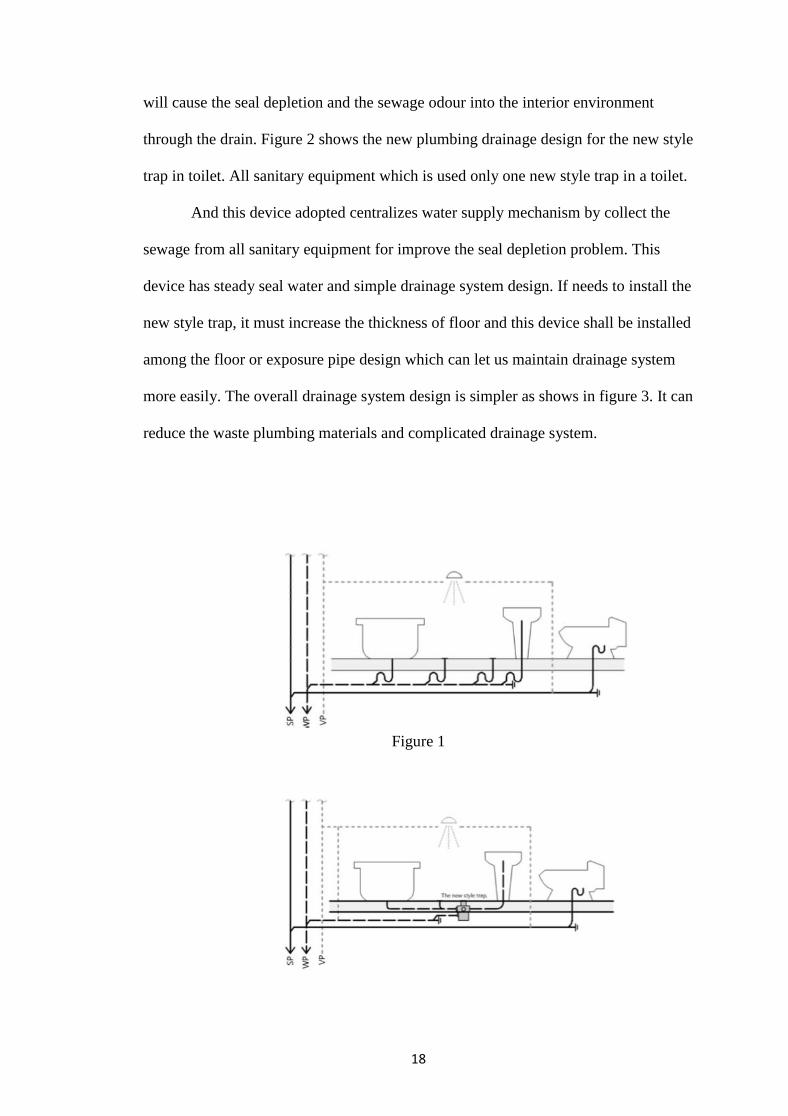
• Figure 1 shows the plumbing drainage design for toilet which was usually adopts
―one sanitary with one trap‖. If the sanitary equipment not be used about 4-5 days, it
18
will cause the seal depletion and the sewage odour into the interior environment
through the drain. Figure 2 shows the new plumbing drainage design for the new style
trap in toilet. All sanitary equipment which is used only one new style trap in a toilet.
And this device adopted centralizes water supply mechanism by collect the
sewage from all sanitary equipment for improve the seal depletion problem. This
device has steady seal water and simple drainage system design. If needs to install the
new style trap, it must increase the thickness of floor and this device shall be installed
among the floor or exposure pipe design which can let us maintain drainage system
more easily. The overall drainage system design is simpler as shows in figure 3. It can
reduce the waste plumbing materials and complicated drainage system.
Figure 1

19
Figure 2
Figure 3
Structure and construction:
• There are four installed type in new style trap which can accord the user needs to
select the construction method. Designer must consider overall drainage system
design for the new style trap in design stages.
First, the construction of the embedded type which is must increase the
thickness of floor and the new style trap shall be installed among the floor as shows in
figure 4. On the other hand, if the trap breakdown or water-tightness reduced, it will
be difficult to find drainage system problem and maintain as shown in the Figure 4.

20
Figure 4
Second, this type adopts the double-floor and the trap shall be installed above
the second floor as shows in figure 5. The second floor can be as partition for the
householder in one story below. So, in order to assure the performance of drainage
system, person can open floor drain cover to make routine maintenance which cannot
affect the residents in one story below. It‘s more suitable for householder with high
indoor environmental quality space and more frequent interior design updates.
Figure 5

21
According to the existing research point out, some country often adopts
exposure pipe design which can easily find drainage system problem and maintain. In
this construction method, it adopts the suspended type as shows in Figure 6. The new
style trap shall be installed under the floor. But limited in residential floor height in
Taiwan, the exposure pipe which would affect use of interior space; lead to the
interior space is uncomfortable. It‘s more suitable for the space with enough the
indoor height, such as office building or department store. Finally, figure 7 shows the
half-buried type. The plumbing design is similar with the suspended type. The half
part of trap shall be installed among the floor. It‘s more suitable for residence house
use.
Figure 6

22
Figure 7
(1)S.C.Chung, (2) C.L. Cheng, Dr. (3) W.J.Liao, Dr (4) S.Y. Chen, Mr. (2012)
Method and apparatus for installing floor drain:
• Most homes use basic systems for plumbing and drain systems. A main water line
usually comes into a home through its foundation. From this location, the waterline
may run to a water heater, which generate hot water.
A plumbing drain trap is a shaped pipe located below or within a plumbing
fixture. Such as a toilet, a sink, or ab-shower drain. A trap can be a U-, S-, or J-
shaped trap, although U- and J-shaped traps are the most common traps used today.
The various shapes are each named for the bends in the traps, which are used to
prevent sewer gases from entering buildings through drain pipes. The bends in the
traps are shaped to retain a small amount of water after use of the fixture. The water
in the trap creates a seal that prevents sewer gases from passing from the drain pipe
back into the building.

23
However, known plumbing traps have certain disadvantages. Many
installations require shallow traps in order to fit against a concrete floor, whether that
concrete florison a first floor or a basement floor, or for a second storey installation.
In the United States, basement floors are typically concrete floors so a shallow trap
must be used for basement drain fixtures. The height of a traps measured from the
bottom of a trap arm at an outlet to the top of the trap dip, also known as the crown
weir. A standard trap height maybe 50mm, for example, but a shallow trap may only
have a trap height of 15mm, for example. When a shallow trap is used, however, the
amount of water in the trap is decreased compared to the amount in a regular trap, and
regular evaporation of water in the trap may cause the water seal to be broken more
quickly, thereby allowing sewer odours and gases to enter into the building.
• Further, installing floor drains can be difficult because more than one professional
typically involved in the installation process. In a standard installation, a plumber will
install the Sub-floor plumbing components and then leave a drain pipe extending
above an estimated floor height that will extend to a desired fixture. Then, a flooring
specialist will finish the flooring above the sub-floor plumbing. Concrete is often
poured around the drain pipe and then a finish flooring surface is installed above the
concrete. Once the concrete is poured, however, it is difficult, if not impossible, to
remove the drain pipe to cut it to the proper height. In order to cut the drain pipe
below the flooring surface after the concrete is poured, the flooring specialist must
chisel the cement around the drain pipe so that there is enough clearance for tools to
cut the drain pipe below the flooring surface. But if the drain pipe is cut before the
concrete is poured, it is difficult to determine the desired length of the drain pipe
necessary to make the floor drains it flush on the finished flooring surface. Thus, an

24
improved method for installing a floor drain to the correct height above a flooring
slab and a plumbing trap is desired.
Eduard Coronado,NuevoLeon (MX); JavierCanales,Monterrey
(MX):PedroGonzalcz,Monterrey HumbertoFlores-Villarreal (6 APRIL 2017)

25
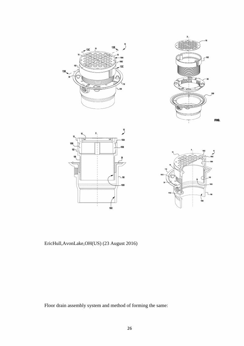
Floor drain assembly and method:
•The present application discloses exemplary embodiment of a drain assembly for
providing a drain in a floor. The drain assembly includes a drain conduit, a strainer
and an adaptor. The drain conduit has an inner surface that defines a fluid flow path
and an outer surface. The strainer is disposed above the drain conduit and has
openings in fluid communication with the fluid flow path of the drain conduit. The
adaptor may be securable in the drain conduit and may be connected to the strainer.
Prior to securing the adaptor in the drain conduit, a position of the adaptor in the drain
conduit may be moveable to allow a top surface of the strainer to be substantially
aligned with the floor. An exemplary embodiment of a method of assembling a drain
in a floor is also disclosed.
26
EricHull,AvonLake,OH(US) (23 August 2016)
Floor drain assembly system and method of forming the same:
27
•In various embodiment, Subfloor panel members are provided that may be
selectively customized. For example, in certain embodiment, at least one of an upper
Sub floor panel and a lower Sub floor panel as shown and described here in-comprise
a honeycomb panel where in the panel may be shaved, cut, moulded, shaped, and/or
compressed to provide a desired slope to the panel. For example, a honey comb panel
may extend substantially horizontally as a flat flooring Surface along a portion of its
area, while being shaped, angled, or tapered toward a drain feature Surrounded by the
panel(s).
There is a need for a bathroom unit flooring solution that is not only
lightweight and structurally durable, and further allows for authentic finishes such as
marble, granite, tile, stone, epoxy, composite or vinyl to be installed over the sub-
floor. Embodiment of the disclosure provide such a solution. The properties of the
honeycomb material provide superb strength and structural support in the sub-floor
materials. The honeycomb material also allows the bisected honeycomb upper sub-
floor to be easily fabricated with a controlled, designed, tapered slope towards the
drain unit to ensure that liquids will be gravity fed to the drain unit. In various
embodiment, lower and upper Sub-floor panels can be machine fabricated to provide
increased accuracy and precision of fit as well as efficient modular production. The
adhesives used are intended to be industry accepted materials for adhering and
securing the component materials in position. The use of a waterproof membrane in
certain embodiment ensures that any water introduced in to the environment will be

28
collected and guided to the drain unit without causing damage to the main floor
system component.
•In one embodiment, a drain assembly is provided for a gravity fed floor drain, the
assembly comprising a subfloor panel, a drain member comprising a drain outlet
extending downward into the Subfloor panel, and a flange extending laterally away
from the drain outlet over at least a portion of the subfloor panel. An adhesive layer is
provided to secure an underside of the flange to the subfloor panel. A flooring
Surface is provided, the flooring Surface comprising a material that is substantially
non-permeable to liquids, the flooring Surface extending outwardly away from the
drain member, and where in the flooring surface comprises a first slope and a second
slope. The first slope is provided at a location distal to the drain member, and the
second slope is provided at a location vertically above and/or within an area defined
by the flange, and the second slope is greater than the first slope to promote drainage
into the drain member.
It is anticipated that the honeycomb Sub-floor panels can be fabricated as a
single piece floor unit or as an assemblage of Smaller section that when combined
create a complete floor unit.

29
DanielNyce,Perkasie, PA(US) (12 FEBRUARY 2017)

30
2.4 SUMMARY
Overall, derived from this chapter is an experiment to be made in reference to
the sources of previous studies to complete the work. Additionally, some information
from trash in floor traps is identified by its function. This implementation can
preserve and conserve the floor trap system.
We can summarize in this project is that we have acquired a lot of knowledge
about clogged floor trap, so in this project we have done the result of our research and
surveys. It is important for a project to conduct research and surveys before starting
the project. This is to know whether the project is being implemented to benefit the
users of the toilets.
This section collects all observations and data obtained through interviews,
magazines, catalogs, books and internet resources. Clear description of each section
and the question of project has been described in this chapter. Explosive ideas and
referral sources have been widely taken on the internet as our main source. All the
filling in the literature review section is based on the deeds cited in the research study
which has taken place on the internet in the last 5 years. Long research has proved to
us that so many applications related to our topics and projects. This literary study
gives us the opportunity we try to meet with officials and companies to make our
main source of reference with only our high courage and confidence. This section
also explains the concepts and theories of our study.

31
In an exemplary embodiment, an improved method of installing a drain fixture
is disclosed. The method comprises installing a Sub-floor plumbing system. Installing
the Sub-floor plumbing system comprises connecting a first end of a plumbing trap to
a main drain outlet and connecting a first end of a removable drain pipe to a second
end of the plumbing trap. The method next comprises sliding a sleeve over the
removable drain pipe. Next, the method comprises building a flooring Surface above
and a round the plumbing trap, the removable drain pipe, and the sleeve. Once the
floor is built, the method comprises partly or fully removing the removable drain pipe
from the sleeve, cutting the removable drain pipe to the desired length and re-
inserting the removable drain pipe through the sleeve and in to the plumbing trap.
32
2.5 REFERENCES
[1] Subhash M. Patil (2014). Building Services (Electro-Mechanical and
Environmental Services). Goregaon (E), Mumbai- 400065 : B.Prints Fort, Mumbai-
400001.
[2] Birdie, G. S., and Birdie, J. S. (1992). Water supply and sanitary engineering.
Dhanpat Rai, New Delhi.
[3] Garg, S. K., and Garg, R. (1996). Sewerage disposal and air pollution engineering:
environmental engineering (vol. 11). Khanna Publishers, Delhi-110006.
[4] P.Venkateswara Rao (2005). ENVIROMENTAL ENGINEERING (For the
Course of Water Supply and Sanitary Engineering). Andhra Pradesh, Hyderabad :
The Telugu Akademi, Hyderabad.
[5] Kelly, D. A., Swaffield, J. A., Jack, L. B., Campbell, D. P., and Gormley,M.
(2008). ―Pressure transient identification of depleted appliance trap seals: A pressure
pulse technique.‖ Build. Serv. Eng. Res. Technol., 29(2), 165–181.
[6] McDougall, J. A., and Swaffield, J. A. (2000). ―Simulation of building drainage
system operation under water conservation design criteria.‖ Build. Serv. Eng. Res.
Technol., 21(1), 41–51.
[7] Swaffield, J. A. (1996). ―Simulation of building drainage flows, waste solid
transport and vent system transients.‖ Build. Serv. Eng. Res. Technol.,17(2), B4–B8.
[8] Swaffield, J. A. (2006). ―Sealed building drainage and vent systems—An
application of active air pressure transient control and suppression.‖ Build. Environ.,
41(10), 1435–1446.

33
[9] Swaffield, J. A., and Campbell, D. P. (1995). ―The simulation of air pressure
propagation in building drainage and vent systems.‖ Build. Environ., 30(1), 115–127.
[10] PN-83/B-03430 Standard: Ventilation in residential buildings, managed
accommodation facilities and institutional buildings. Specification, PKN, 1983, (in
Polish).
[11] PN-83/B-03430:Az03 Standard: Ventilation in residential buildings, managed
accommodation facilities and institutional buildings. Specification. Amendment Az3
PKN, 2000, (in Polish).
[12] Dz.U. No. 75 of 2002, item 690 - the Regulation of the Minister of Infrastructure
of 12 April 2002 on technical conditions of buildings and their location, 2002, (in
Polish).
[13] M. Telejko , J. Z. Piotrowski, Distribution of ventilation air in buildings with
airtight insulation, Building physics in theory and practice, vol. IV, pp.183-186, (in
Polish).
[14] E. Zender-Świercz, Analysis of the impact of the parameters of outside air on the
condition of indoor air. International Journal of Environmental Science and
Technology August 2017
[15] J. Z. Piotrowski, E. Zender-Świercz, M. Telejko, The Influence of a sealed
building envelope on the distribution of ventilation air, Energia i Budynek 7/2010, pp.
23-25 (in Polish). [16] E. Zender-Świercz , M. Telejko, Impact of Insulation Building
on the Work of Ventilation, Procedia Engineering Vol. 161, pp. 1731-1737
[17] L. Śliwowski, Interior microclimate and thermal comfort of people in rooms,
Wroclaw University of Technology Press, Wroclaw, 2000 (in Polish)

34
[18] ASHRAE HVAC Fundamentals Handbook, 2001
[19] EN 15251:2012-12 Indoor environmental input parameters for design and
assessment of energy performance of buildings addressing indoor air quality, thermal
environment, lighting and acoustics
[20] K. F. Nielsen, G. Holm, L. P. Uttrup, P.A. Nielsen, Mould growth on building
materials under low water activities. Influence of humidity and temperature on fungal
growth and secondary metabolism, International Biodeterioration & Biodegradation
54(4):325-336, December 2004
[21] M. Telejko, J. Z. Piotrowski, Distribution of ventilation air in buildings with
airtight insulation, Building physics in theory and practice, vol. IV, pp.183-186, (in
Polish).
[22] PN-EN 12831-1:2017-08 Standard: Energy Performance of Buildings – Method
for Calculation of the Design Heat Load – Part 1: Heat Load, Module M3-3, (in
Polish).
[23] ASHRAE Standard 62.1-2016, "Ventilation for Acceptable Indoor Air Quality‖
[24] C.L. Cheng, W.J. Liao, K.C. He, C.J. Yen, 2008, A Non-Destructive Testing
Method and Analysis for Air Pressure Distribution in the Stacks of Building Drainage
Systems, 2008 ASME Pressure Vessels and Piping Division Conference, July 27–31,
2008, Chicago, Illinois, USA.
[25] J.A.Swaffield and D.P.Campbell, Numerical modelling of air pressure transient
propagation in building drainage system, including the influence of mechanical
boundary condition. Building Envir. 27, (1992)

35
[26] K. Sakaue, M. Kamata, N. Tsukagoshi , T. Kurabuchi,Xingming Sun, A Study
on the Method of Performance of Traps Using the Testing Device with Autuator,
CIB-W62 International Symposium,Japan
[27] Cheng-Li Cheng, Chia-Ju Yen, Wen-Hung Lu, Kuen-Chi Ho,2007, An
Empirical Approach to Determine Peak Air Pressure within the 2-Pipe Vertical
Drainage Stack. CIB-W62 Symposium, Brno, Czech Republic, Journal of the Chinese
Institute of Engineers
[28] Wei-Lun Lin, 2008, The research of life cycle assessment method and visual
simulation in Building drainage systems, Master thesis Of National Taiwan
University of Science and Technology Institute of Architecture, Taiwan.

36
CHAPTER 3
METHODOLOGY
3.1 INTRODUCTION
The effectiveness of this study is to ascertain whether the trash traps are
influenced by several factors such as waste capacity, physical characteristics of solid
waste and trash type. In ensuring that this trash can work properly, it should be
monitored and systematically managed from time to time. With this, the use of waste
traps can last longer while saving costs and to facilitate the maintenance of pipes to
the toilet users. This can reduce the problem of stagnant and clogged flooring that
often occurs and can creates a clean bathroom atmosphere.
The methods section describes actions to be taken to investigate a research
problem and the rationale for the application of specific procedures or techniques
used to identify, select, process, and analyse information applied to understanding the
problem, thereby, allowing the reader to critically evaluate a study‘s overall validity
and reliability. Additionally, to help understand more about (more detail) about the
application of the method by making a description of the review process.
This chapter also gives an outline of research methods that were followed in
the study. It provides information on the participants, that is, the criteria for inclusion
in the study, who the participants were and how they were sampled. The researcher
describes the research design that was chosen for the purpose of this study and the
reasons for this choice. The instrument that was used for data collection is also
described and the procedures that were followed to carry out this study are included.
The researcher also discusses the methods used to analyse the data. Lastly, the ethical
issues that were followed in the process are also discussed.

37
3.2 RESEARCH DESIGN
Figure 3.2 Methodology flow chart
Identifying
Problems
Implementation
Analysis
Design
System

38
3.2.1 Identifying Problems
At the beginning of this study, it was to identify the problem many wastes are
clogged in the floor trap pipes that cause stagnant and dirty bathroom floors, which
cause difficulties for the users to wash dirt thrown into the floor traps in the
community at Blok Damai 1, 2, 3 and 4 (KAMSIS). Hence, careful planning has been
undertaken to address the problem by designing a trash trap into the floor trap. This is
due to the most users simply left or throw dirt or trash into the floor traps on the
toilets.
3.2.2 Analysis
The data collected are collected, processed and analysed to enable the next
steps to be taken and the determination of the research done as required in the
objective.
3.2.3 Design
Before a trash trap was implemented, the product was design to know the
dimension of the floor trap in Blok Damai (KAMSIS) In fact, this design is intended
to be prior to execution, it can be illustrated before the project is implemented and
even this design will provide more detailed information to build a trash trap that are
operating well.
3.2.4 Implementation
When a trash trap has been completed, the trash trap must be tested on the
floor trap to determine whether it is stable or vice versa to the floor trap and easily to
make maintenance of the trap. Subsequently, the use of plat iron and wire mesh
stainless steel was selected to build the trash trap.
3.2.5 System
When the Bath Waste Filter (BWF) has achieved its desired objectives, the
product will be placed on the Blok Damai (KAMSIS) and the reduction of trash can
be overcome to avoid health problems occur to the toilet users.

39
3.2.6 Project flow chart
Start
Project briefing
Project group selection
Selection of project title
Preparation of project proposal
Checking of project proposal
Presentation 1
Accepted
Yes
Project activity implementation and preparation report
Review of project result and final report
Accepted?
Submission of project result and final report
Presentation 2
End
yes
No
No

40
3.3 DATA COLLECTION METHODS
To carry out this study, data collection methods have been practiced obtaining
the data that are essential for the analysis stage. Among the methods of data
collection is the questionnaire. Data collection can be classified into 3 types, primary
data, secondary data and sampling.
3.3.1 Primary Data
Primary data are important data in the study. Without the main data, the
objective of the study will not be achieved. The data collection process was carried
out through the distribution of questionnaires to respondents.
3.3.2 Secondary Data
Secondary data comprises literature studies and other sources such as books
related to study field, journals and other publications related to research conducted.
These materials are analysed accordingly and become the basis of reference to this
study.
3.3.3 Sampling
The sampling involves the provision of waste to be tested on trash traps. The
types of waste for this study are hair and other waste that could inside the floor trap.
This waste is first weighed to determine the original weight of the waste. Then, trash
trapped on the trap is taken and dried before weighed. Furthermore, the percentage of
retained waste will be calculated. This sampling is to determine the quantity of trash
trapped in the trap.

41

42

43

44
3.4 STUDY INSTRUMENTS
In this research instrument, the questionnaire was selected. Respondents'
selection consists of Polytechnic Sultan Azlan Shah. The questionnaire used consists
of 7 question. The questionnaires consist:
a) Respondents Demographics (Gender, Age)
b) A general view of the study
c) The respondent's perspective on the product

45
3.4.1 Product Income
Here is how to produce a Bath Waste Filter (BWF)
Figure 3.4.1 (i)
Figure 3.4.1 (i) shows the first step in producing Bath Waste Filter (BWF).
The iron plate is first set according to the designated size. The next step is to cut the
iron plate in the shape of a circle (diameter 8cm) to make the holder to the floor trap.
This concept was created to facilitate the product to be washed.
Figure 3.4.1 (ii)

46
After completion of the iron plate part, proceed with the round stainless steel
(23cm length) with welding as shown in figure 3.4.1 (ii).
Figure 3.4.1 (iii)
The next step is cutting the wire mesh (23cm length) and welding the iron
plate that have iron rod around the iron plate with wire mesh as shown in figure 3.4.1
(iii).
Lastly, this filter is designated with an opener at the bottom of the filter. This
will make it easier for users to remove and clean this filter. The filter is complete as in
the Figure 3.4.1 (iv) and ready to use.

47
3.5 SAMPLING TECHNIQUE
After collecting data through questionnaire and sampling, data analysis was
made using the Google Forms. The software will analyse the questionnaires
containing 7 questions related to the study. Data analysers can be divided into two
parts: forming analytical and quantitative analysis models.
3.5.1 Analysis Model
In doing this analysis model, mathematical model is used. It aims to facilitate
data analysts. The applied mathematical model refers to a predictive model. Given the
effectiveness and relevance of the model, the technique of recreation is used. It was
able to control the variability of variability with other variables of variability that
were also tested in analysts. The findings of this study will be presented using a pie
chart, bar graph and table. Selection of the method is done because the assessment is
easy to do, and the results obtained are easy to understand.
3.5.2 Quantitative Analysis
For quantitative analysis, the data collected must have a uniform distribution.
It is aimed not to have extreme values that would cause the bias and inaccuracies in
the analysis. To carry out this analysis, Google Forms is used.
3.6 DATA ANALYSIS METHOD

48
In the process of analysing this, the data collected will be analysed and the
results will be presented in the form of pie charts and tables.
3.7 SUMMARY
In the initial stages, the design of the study, data collection methods, research
instruments, data sampling techniques and data analysis methods were systematically
made in the methodology study to find out the facts and information to support the
research instrument and illustrate more clearly in this study. After analysing the data,
it is important to make conclusions on the results and hypotheses whether the trap is
effective or not. From chapter 1 and chapter 2, information about existing floor trap
filter were being searched to get ideas for this project and comparison is made. In this
chapter is also about the methods on how to make the bath waste filter project.

49
CHAPTER 4
RESULTS
4.1 INTRODUCTION
Once all the data and information has been obtained, the analysis is done to
see the effectiveness of the installation of waste traps installed on premises such as
residences, hostels and public toilets.
The results obtained in this chapter are the results obtained from the
questionnaire and experiments conducted in the study area. The results of the
experiments in the study area are analyse in more detail to draw conclusions based on
the stated objectives of the study.
The study was conducted using 46 respondents from the users. There are
several aspects that are the focus:
1) Respondent Demographics (gender and age)
2) General view of the study
3) Respondents' perspectives on the Bath Waste Filter Platform: -
i. Shape
ii. Functions
iii. Materials used
50
iv. Advantage
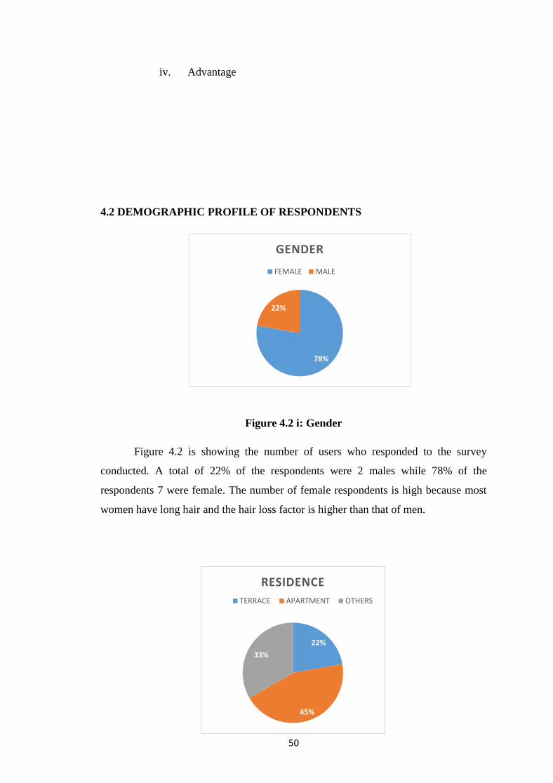
4.2 DEMOGRAPHIC PROFILE OF RESPONDENTS
Figure 4.2 i: Gender
Figure 4.2 is showing the number of users who responded to the survey
conducted. A total of 22% of the respondents were 2 males while 78% of the
respondents 7 were female. The number of female respondents is high because most
women have long hair and the hair loss factor is higher than that of men.
78%
22%
GENDER
FEMALE MALE
22%
45%
33%
RESIDENCE
TERRACE APARTMENT OTHERS

51
Figure 4.2 ii: Residence
Furthermore, the results of the study found that 4 respondents, of whom 45%
were lived at apartment, answered this questionnaire. In addition, a total of 3
respondents were lived at others building of whom 33%, which is at hostel block.
Other than that, 2 respondents, of whom 22% lived at terrace house.
4.2.1 Component cost
Table 4.2.1: Component cost
Table 4.2.1 shows the cost of materials allocated to implement the ‗Bath
Waste Filter‘ (BWF) project. We use stainless steel plates that are mould into
cylinders. Later, we also hired in-store to weld iron to form our products. Next, we
bought a stainless-steel floor trap.
4.3 FINDINGS
4.3.1 Site Survey Data
The data obtained during the site study activities will be evaluated based on
the weight of the waste that was successfully collected in this floor trap filter. These
data will eventually be displayed in the form of tables and graphs of toilet weight.
The rest of the baths will be weighed and recorded in the data table. In addition, the
weight of this bath will be absorbed and displayed in the table provided.
4.3.2 Data analysis
The process of analyse the study data will be presented in the form of tables
and charts. This floor trap filter analysis includes the amount of waste found in the
NO. ITEM QUANTITY TOTAL (RM)
1. Stainless steel 1 RM45
2. Stainless steel floor trap 1 RM22
3. Welding 1 RM50
4. Stainless steel Hinge 1 RM1
TOTAL RM118

52
filter. The results of the data analysis results will be presented in the form of data
scheduling. In the method of observation, the method for removing wastes collected
on floor traps is to drain them through open floor traps.
4.3.2.1 Research questionnaire
To further strengthen this research, the questionnaire was conducted by
involving PSA students and a family. The data obtained will be formatted as a table
for easy information analysis and analysis. The following is information related to the
survey conducted.
Figure 4.3.2.1 i:
Figure 4.3.2.1 i: shows that there are 58% occupants in a residential area of 9
to 12 people, while there are 23% occupants in a residential area of more than 13
people and 19% occupants in a residential area of 2 to 4 people.
19%
0%
58%
23%
NUMBER OF OCCUPANT IN RESIDENCE
2<4 5<8 9<12 >13

53
Figure 4.3.2.1 ii:
Figure 4.3.2.1 ii: shows 3 to 4 times the occupants use the bathroom in their
home, of which 56%. Whereas, 33% occupants use more than 5 time the occupants of
the bathroom in their home, and at least 11% occupants use the bathroom1 to 2 times.
11%
56%
33%
FREQUENTLY OF USING BATHROOM IN A DAY
1<2 3<4 >5

54
Figure 4.3.2.1 iii:
Figure 4.3.2.1 iii: shows 89% occupants at their house aware the existence of
floor traps in their bathroom and only 11% occupants of their home may be aware of
floor traps in the bathroom.
89%
0% 11%
DID YOU KNOW THE EXISTENCE OF FLOOR TRAP IN THE
BATHROOM?
YES NO MAYBE

55
Figure 4.3.2.1 iv:
Figure 4.3.2.1 iv: shows how the occupants dispose of the waste on the floor
traps and 46% of them collect the waste, while 27% occupants open the traps and
allow the waste to enter the pipeline and use equipment to dispose of waste.
27%
46%
27%
THE WAY HOW TO THROW THE WASTE AT FLOOR TRAP
Open the floor trap and let the waste flow through the pipe
Take the waste at the floor trap
Used the equipment to throw the waste

56
Figure 4.3.2.1 v:
Figure 4.3.2.1 v: shows 67% occupants having stagnant bathroom problems
due to residue on floor traps and 33% occupants not having stagnant bathroom
problems.
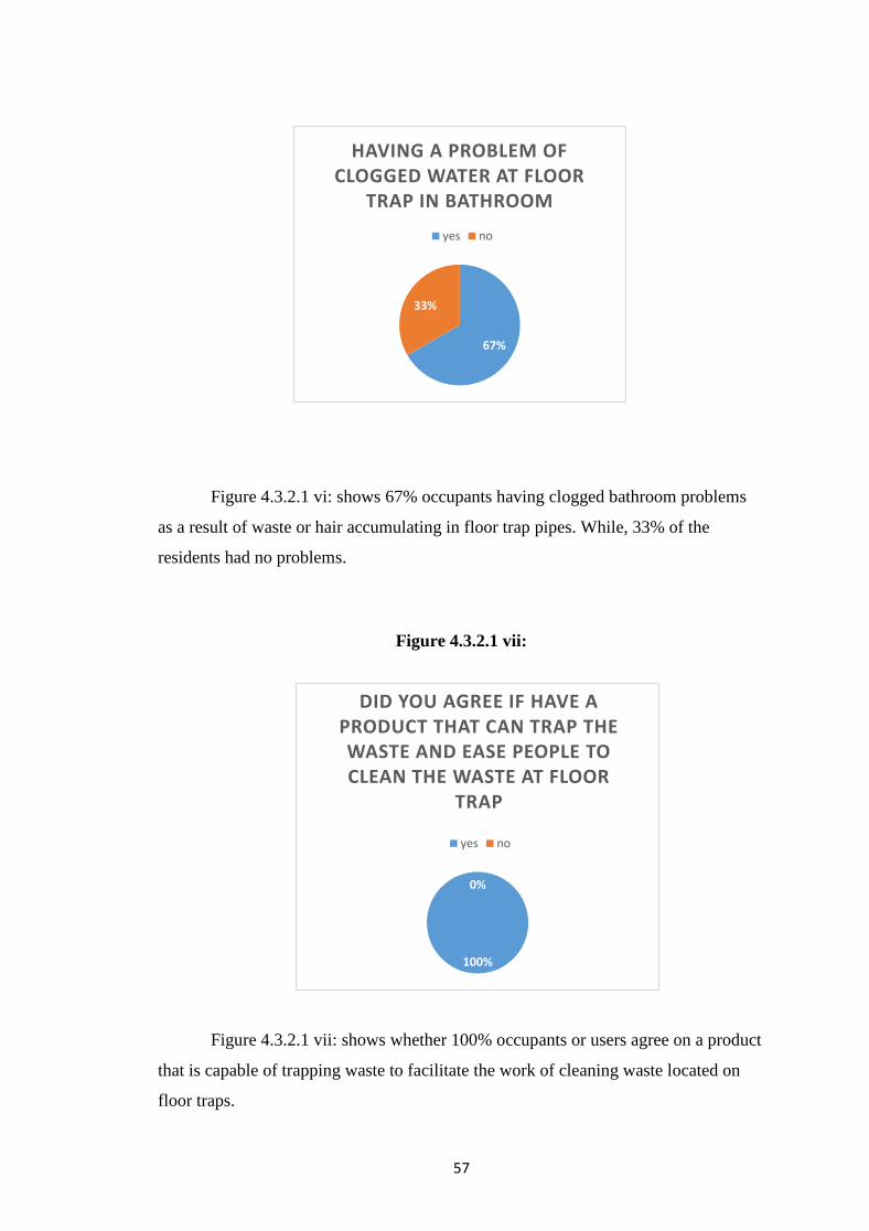
Figure 4.3.2.1 vi:
67%
33%
HAVING A PROBLEM OF STAGNANT WATER IN THE
BATHROOM
yes no
57
Figure 4.3.2.1 vi: shows 67% occupants having clogged bathroom problems
as a result of waste or hair accumulating in floor trap pipes. While, 33% of the
residents had no problems.
Figure 4.3.2.1 vii:
Figure 4.3.2.1 vii: shows whether 100% occupants or users agree on a product
that is capable of trapping waste to facilitate the work of cleaning waste located on
floor traps.
67%
33%
HAVING A PROBLEM OF CLOGGED WATER AT FLOOR
TRAP IN BATHROOM
yes no
100%
0%
DID YOU AGREE IF HAVE A PRODUCT THAT CAN TRAP THE WASTE AND EASE PEOPLE TO CLEAN THE WASTE AT FLOOR
TRAP
yes no

58
The questionnaire conducted on the occupants of the residence is to know the general
opinion of the study. From the results of the study, it is known that:
i. 46% of residents say they collect garbage or waste found on a floor trap.
ii. 67% of residents said they had problems with the bathroom clogging and
stumbling around in the bathroom.
4.3.2.2 Data capture
i. Data capture in three homes:
Date: 1 September 2019 - 23 September 2019
PLACE WEEK 1 WEEK 2 WEEK 3 TOTAL
Girl‘s occupants at Kamsis Damai 12g 7g 16g 35g
Girl‘s occupants at Perdana
Apartment
12g 12g 14g 38g
Boy‘s occupant at Terrace House
TTDI Jaya
1g 2g 2g 5g
Figure 4.3.2.2 a:

59
Figure 4.3.2.2 a) that is 38g of data that can be weighed and collected for three weeks
from the scope of the premises in Apartment Perdana.
Figure 4.3.2.2 b:

60
Figure 4.3.2.2 b) is that there is 5g of data that can be weighed and collected for three
weeks from the scope of the TTDI Terrace house.
Figure 4.3.2.2.c:
Figure 4.3.2.2 c) is that there is 35g of data that can be weighed and collected for
three weeks from the scope of the Peace Area.
CHAPTER 5
DISCUSSION AND CONCLUSIONS
5.1 INTRODUCTION
For this chapter, the decisions made are based on all the results obtained from
the experiments and discussions in the preceding chapters. In this chapter also, the
relevant matters pertain to the objectives of the study as well as the recommendations
of the study conducted. Moreover, conclusions have been drawn for this experiment.

61
5.2 DISCUSSION
For Bath Waste Filter, data collection tests have been conducted throughout
this three-week process. The tests were carried out at selected locations, at Perdana
Apartment, Damai Kamsis Block 4, and terrace house at TTDI. In addition, the
effectiveness of this Bath Waste Filter is based on the amount of hair and waste
collected.
5.3 CONCLUSION
The main objectives of this study were to identify the cost savings that can be
obtained in maintaining the floor trap in the bathroom and designing a floor trap to
trap the waste through the floor trap in the bathroom.
In this study, the effectiveness of Bath Waste Filter was more focused on the
quantity and waste accumulated. Most of the residue that is trapped is hair and small
particle of waste. In the assessment made, the overall Bath Waste Filter are effective
and meet the design requirements and require low cost of manufacture.
In addition, the workforce needed in the process of making this product is four
people. This Bath Waste Filter needs to be washed or cleaned if there is a lot of waste
or hair accumulated in it to prevent clogging. If this happens, it is feared that the Bath
Waste Filter will cause stagnant water in the bathroom.
Having a Bath Waste Filter makes it easier to clean the rest of hair or collect
the hair at the floor trap. In addition, it will also help to release the duct system from
being blocked by hair or small particles trapped at the floor trap.
5.4 PROPOSAL
The following are some of the things that are proposed to further enhance the
research that will be done on Bath Waste Filter to find out its effectiveness: -
1) The holes at the filter should be smaller.
2) Using materials made of plastic.
3) Provides a handle to make it easy for users to take out the Bath Waste Filter.

62
5.5 SUMMARY
As a result of the experiments conducted on the Bath Waste Filter, it can be
concluded that Bath Waste Filter has achieved its objective of saving cost
maintenance and designing a floor trap to trap the waste through the floor trap in the
bathroom.
Also, after a few weeks of being put in the bathroom in some places, it has been
proven to be effective and useful to all occupants who use the bathroom as it
facilitates the work of cleaning the small particle of waste or accumulated hair.
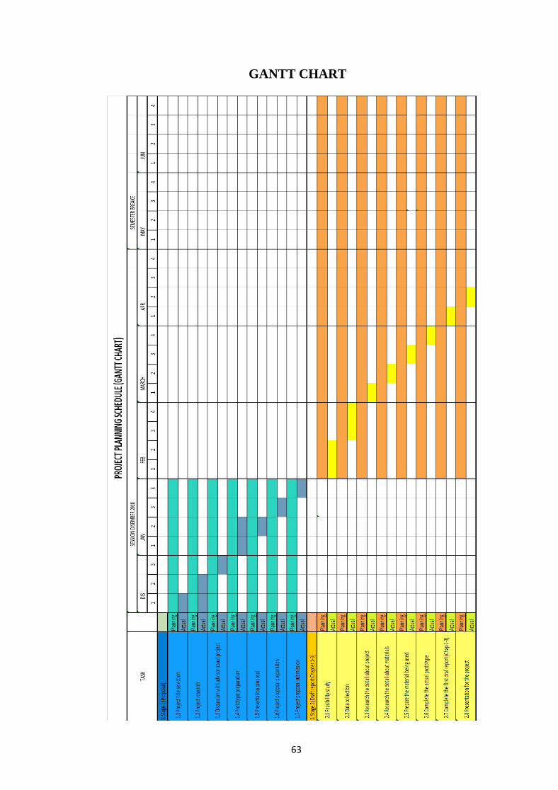
63
GANTT CHART

64
GANTT CHART

65
APPENDIX

66
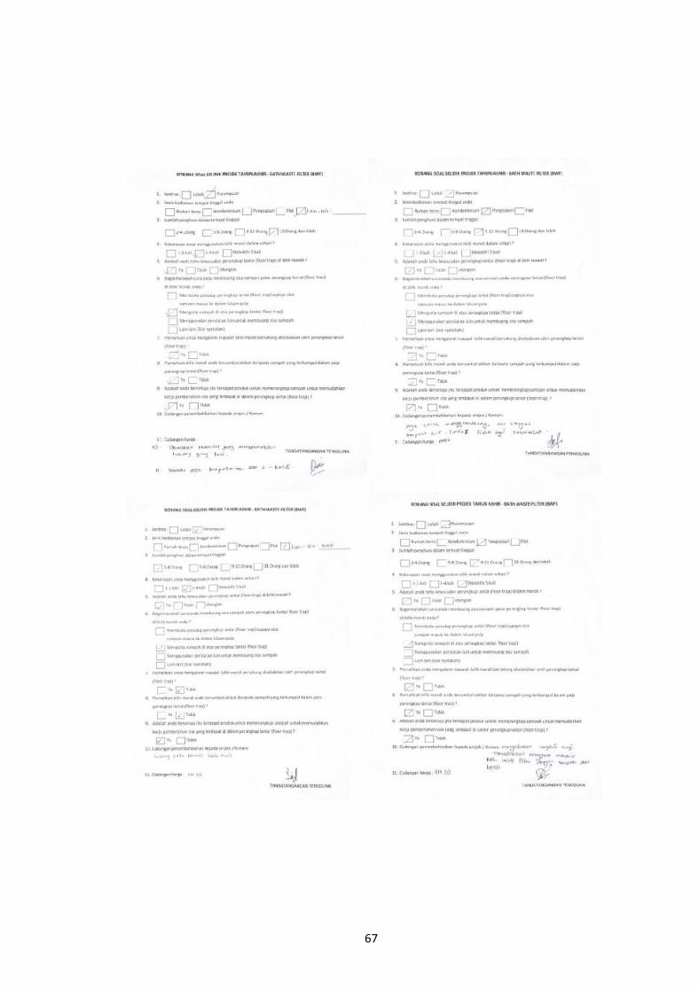
67

68

69
BROCHURE