carbon-carbon composites - 可计量的导热系数 ... · printed on permanent acid-free text...
TRANSCRIPT

Carbon-Carbon Composites

Carbon-Carbon Composites
G. Savage
SPRINGER-SCIENCE+BUSINESS MEDIA, B.V.

First edition 1993
© 1993 G. Savage Originally published by Chapman & Hall Softcover reprint of the hardcover 1st edition 1993
Typeset in 10/12pt Times by Graphicraft Typesetters Ltd, Hong Kong
ISBN 978-94-010-4690-9
Apart from any fair dealing for the purposes of research or private study, or criticism or review, as permitted under the U K Copyright Designs and Patents Act, 1988, this publication may not be reproduced, stored, or transmitted, in any form or by any means, without the prior permission in writing of the publishers, or in the case of reprographic reproduction only in accordance with the terms of the licences issued by the Copyright Licensing Agency in the U K , or in accordance with the terms of licences issued by the appropriate Reproduction Rights Organization outside the UK. Enquiries concerning reproduction outside the terms stated here should be sent to the publishers at the London address printed on this page.
This publisher makes no representation, express or implied, with regard to the accuracy of the information contained in this book and cannot accept and legal responsibility or liability for any errors or omissions that may be made.
A catalogue record for this book is available from the British Library
Library of Congress Cataloging-in-Publication data enclosed
Savage, G. (Gary) Carbon-carbon composites / G. Savage. — 1st ed.
p. cm. Includes index. ISBN 978-94-010-4690-9 ISBN 978-94-011-1586-5 (eBook) DOI 10.1007/978-94-011-1586-5
1. Carbon composites. 2. Carbon fibers. 3. Fibrous composites. I. Title. TA418.9.C6S249 1992 620.1'93—dc20 92-27294
CIP
® Printed on permanent acid-free text paper, manufactured in accordance with the proposed ANSI/NISO Z 39.48-199X and ANSI Z 39.48-1984
Contents
Preface ix
1 Introduction 1 1.1 Carbon 1 1.2 Bonding in carbon materials 1 1.3 Order and disorder in carbon materials 10 1.4 Techniques for characterizing the structure of carbons 13 1.5 Definitions of carbon forms and processes 26 1.6 Carbon composites 29 1.7 Carbon-carbon composites 31
2 Carbon fibres 37 2.1 Introduction 37 2.2 Processing of carbon fibres 41 2.3 The structure of carbon fibres 57 2.4 Commercially available fibres 62 2.5 Surface treatment of carbon fibres and interfacial
bonding 64 2.6 Carbon fibre product forms 65 2.7 Footnote 80
3 Gas phase impregnationldensification of carbon-carbon and other high-temperature composite materials 85 3.1 The CVD Process 85 3.2 Physico-chemical Principles of the CVD Process 86 3.3 Experimental CVD techniques 93 3.4 CVD processing of carbon-carbon composites 99 3.5 CVD processing of ceramic matrix composites 107 3.6 A brief survey of commercial CVD composite
fabrication processes 112 3.7 Summary 113
vi I I CONTENTS
4 Thermosetting resin matrix precursors 117 4.1 General considerations 117 4.2 Isotropic carbon 118 4.3 Carbon yield from polymers 120 4.4 Carbonization of polymers 124 4.5 Carbonization of composites 134 4.6 Graphitization 137 4.7 Impregnation technology 139 4.8 High carbon yield matrix precursors 150
5 Thermoplastic matrix precursors 157 5.1 Introduction 157 5.2 Pitch 158 5.3 Characterization of pitches 159 5.4 Pyrolysis of pitch 161 5.5 Carbon yield from pitch 170 5.6 The influence of additives on carbonization 173 5.7 Control of microstructure in pitch-derived
carbon--carbon composites 173 5.8 Low-pressure composites processing 175 5.9 High-pressure processing of pitch-derived
carbon--carbon 176 5.10 Thermoplastic polymer matrix precursors 181 5.11 Summary 187
6 Oxidation and oxidation protection 193 6.1 Introduction 193 6.2 Oxidation behaviour of carbon--carbon 197 6.3 Fundamental concerns in the oxidation
protection of carbon--carbon composites 205 6.4 Protection at temperatures below 1500 °C 208 6.5 Protective coatings for the 1500-1800 °C range 211 6.6 Oxidation protection at temperatures in excess of
1800 °C 216 6.7 Summary 219
7 Laboratory scale production and evaluation of carbon-carbon 227 7.1 Introduction 227 7.2 Raw materials 227 7.3 Densification of composites by CVD 228 7.4 Fabrication of thermoset resin laminated precursors 231 7.5 Processing thermoplastic precursors 237 7.6 Graphitization of carbon-carbon 243

CONTENTS
7.7 Mechanical testing of carbon-carbon 7.8 Microscopy 7.9 Density and porosity measurements 7.10 Oxidation and oxidation protection 7.11 Measurement of thermal conductivity
8 The properties of carbon-carbon composites 8.1 General considerations 8.2 Microstructure 8.3 Interfaces in carbon-carbon composites 8.4 Mechanical properties 8.5 Thermal properties 8.6 Electromagnetic properties
9 Applications of carbon-carbon composites 9.1 Brakes and clutches 9.2 Rocket motors 9.3 Heatshields for re-entry vehicles 9.4 Aero-engine components 9.5 Industrial applications 9.6 Biomedical devices 9.7 Summary
10 Technology summary and market review 10.1 Summary 10.2 The state of the art 10.3 The carbon-carbon market 10.4 Commercializing a product 10.5 Organization of the carbon-carbon business 10.6 Major companies in the carbon-carbon market 10.7 Conclusion
Index
I I vii
246 268 270 271 273
277 277 278 285 290 309 317
323 323 346 349 351 354 356 357
361 361 362 369 373 376 378 382
385

For Grandad

Preface
Carbon fibre reinforced carbon composites form a very specialized group of materials. They may be considered as a development of the family of carbon fibre reinforced polymer composites which are becoming ever more prevalent in modern engineering. Since the early 1960s a large number of so-called 'advanced materials' have appeared on the scene. Carbon~arbon is arguably the most successful of all these products finding many and varied applications. In the field of Formula 1 motor racing for example, the present levels of performance simply could not be achieved without the use of carbon-carbon brakes and clutches. Despite the materials' obvious assets, they have not, and will not, reach their full potential until their inherent problems of excessive production costs and oxidation resistance have been addressed properly. In this respect the 'carbon-carbon story', of much potential but only limited success, serves as a lesson to all those involved in materials research, development and application.
In writing this book I have tried to set up a logical progression of what the materials are, how they are made, what their assets and deficiencies are, what they are used for and to what extent they are commercially exploited. Each specialized chapter may be considered in isolation or as part of a sequence, whereas the final chapter provides a summary of the principal concepts as well as a basic review of the economic situation past, present and, hopefully, future.
Carbon itself is a unique material around which a whole branch of science has developed. The first chapter introduces carbon-carbon composites with respect to their relationship to other carbon materials, from whence they derive many of their properties. This chapter should be of particular interest to those not familiar with carbon science in that it introduces many of the principles and much of the terminology expanded later in the text. Like any other fibre reinforced composite, the engineering and many of the physical properties of carbon~arbon are dominated by those of the reinforcing fibres. The second chapter therefore consists of an introduction to carbon fibres, covering their production and properties as well as the techniques used to process them into intermediate products such as fabrics and preforms. It is hoped that this review will be equally apposite to those
x I L-I ________ P_RE_F_A_C_E _______ -----'
involved in the 'conventional' composites industry. Each of the major production methods is covered in a separate chapter highlighting not only the attractive aspects of the technique but also the problems which have resulted in high costs and inefficiency. Aside from high cost the other major drawback of carbon-carbon is its susceptibility to oxidation. The problem is so acute that it merits a complete chapter. The oxidative degradation is covered in detail along with remedies which have been and are currently being developed.
One of the primary aims of this book is to aid the reader who wishes to engage in the research and development of carbon-carbon materials. In most texts on composites carbon-carbon (if mentioned at all) it is usually only given a few lines at the end of the book. As a redress, Chapter 7 consists of a detailed description of the techniques used to fabricate, test and analyse the materials on a laboratory scale. The remaining chapters cover the properties of the various forms of carbon-carbon, its uses and applications and finally a brief overview of the technology and the market and economic potential. Throughout the book, a theme is developed of carbon-carbon not being a single material but rather a whole family whose properties are capable of being tailored to meet specific applications. To this end, the chapter on materials' properties consists not of a list of the properties of commercial products, but a discussion of the principles governing the way properties are developed and may be altered.
In preparing this book a great deal of help in terms of information and photographs has been provided by a number of people and their organizations whom I would now like to thank very much, in no particular order: Gavin Gray of ICI, Shelley Gildersleve of Capricorn-Fulton, Pergamon Press, Elsevier Science publishers, Rob Simmonds of AP racing, Graham Goldsmith of Gaybo International Kayaks Ltd, Aoki-San from the Tonen Corporation, Chris Mellings of Ciba-Geigy, Perry Bruno and Neil Hansen of Hercules/RTAC, Dr Jim Williamson, Dr Rees Rawlings, Ian Davies and Margaret Campbell from Imperial College, Brian O'Rourke of Williams Grand Prix Engineering, Dr Richard Alexander of Mitsubishi Kasei Corporation, Steve Beebe, Peter Stulgaitis and Graham Rogers of Instron.
Many thanks are due to my friend Dr John Runnacles of Fiberite for his help in proof reading the manuscript and in provision of information expecially on CVD, to my 'oppo' Paul Cox for his painstaking draughting of many of the figures and Dr Jim Williamson of Imperial College for refereeing the text and helping to make it more 'readable'. Finally I would like to thank my father Malcolm Savage for arranging the typing and providing encouragement, along with my wife Liz, when my enthusiasm was flagging. Once again, thank you all very much.
Gary Savage 1992

~ _____ I_n_tr_o_d_u_ct_io_n ______ ~I~
1.1 CARBON
Carbon has an atomic weight of 12.011 and is the sixth element in the periodic table. Three isotopes are known to exist, these being C12, C13 and cl 4, the first two of which are stable. C12 accounts for around 99% of the naturally occurring carbon and is used as the reference definition of atomic mass. It is defined as having a 'relative atomic mass' of 12[1]. C13 has a magnetic moment (spin = t) which results in its being used as a probe in nuclear magnetic resonance (NMR) studies, although its low abundance induces lengthy acquisition times. The radioactive isotope C14 is generated in the earth's upper atmosphere by the interaction of neutrons with nitrogen:
(1.1)
C14 has a very long half-life of 5730 years and is used extensively in the dating of archaeological artefacts and as a 'label' in the study of organic reaction mechanisms.
The properties of carbon-based materials depend upon its electronic configuration. Despite the electronic ground state of carbon being 1s2, 2S2, 2p2, energetic advantage is gained from involving all four outer orbital electrons in bonding between other atoms or carbon atoms themselves. Carbon displays 'catenation' (bonding to itself) to such a degree that the number of resulting chains, rings and networks are almost limitless.
1.2 BONDING IN CARBON MATERIALS
1.2.1 Quantum mechanics
Quantum or wave mechanics is based on the fundamental principle that electrons show the properties not only of particles, but also of waves (they may, for example, be diffracted), and as a result, therefore, a wave equation can be written for them, in the same sense that light and sound waves,
2 I I'---_________ INT __ R_O_D_U_CT_IO_N ________ --.---I
z
y x
(a) (b)
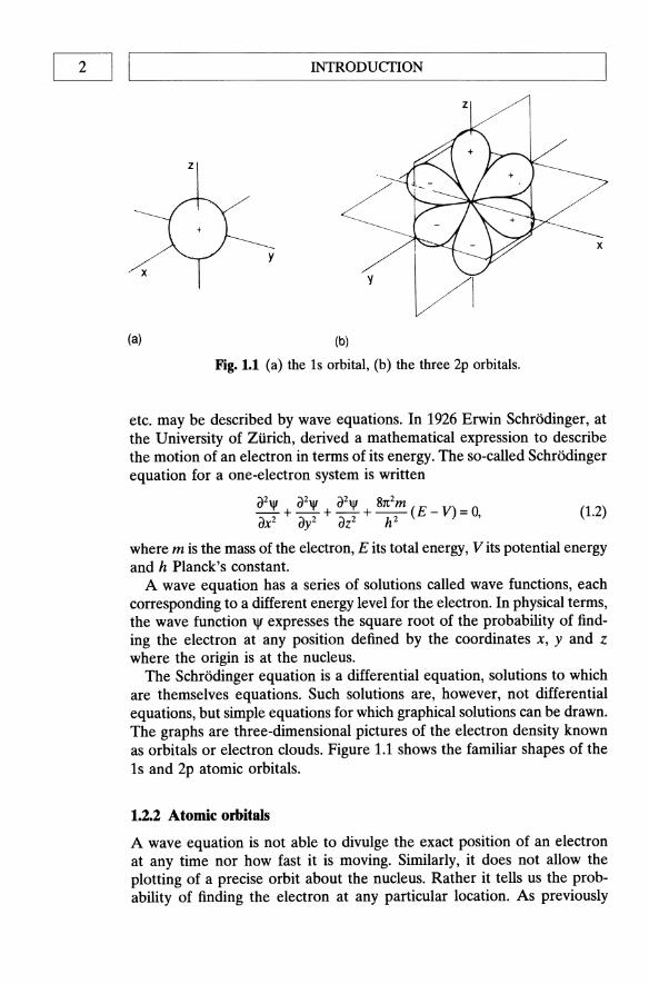
Fig. 1.1 (a) the is orbital, (b) the three 2p orbitals.
etc. may be described by wave equations. In 1926 Erwin SchrOdinger, at the University of Zurich, derived a mathematical expression to describe the motion of an electron in terms of its energy. The so-called Schrodinger equation for a one-electron system is written
{)2'1' + {)2'1' + {)2'1' + 81t2m (E _ V) = 0, {)x2 {)y2 {)Z2 h2
(1.2)
where m is the mass of the electron, E its total energy, V its potential energy and h Planck's constant.
A wave equation has a series of solutions called wave functions, each corresponding to a different energy level for the electron. In physical terms, the wave function 'l' expresses the square root of the probability of finding the electron at any position defined by the coordinates x, y and z where the origin is at the nucleus.
The SchrOdioger equation is a differential equation, solutions to which are themselves equations. Such solutions are, however, not differential equations, but simple equations for which graphical solutions can be drawn. The graphs are three-dimensional pictures of the electron density known as orbitals or electron clouds. Figure 1.1 shows the familiar shapes of the 1s and 2p atomic orbitals.
1.2.2 Atomic orbitals
A wave equation is not able to divulge the exact position of an electron at any time nor how fast it is moving. Similarly, it does not allow the plotting of a precise orbit about the nucleus. Rather it tells us the probability of finding the electron at any particular location. As previously

L--_____ B_O_N_D_IN_G_IN_C_A_RB_O_N_M_A_TE_R_I_A_L_S _____ ---'I I 3
stated, the region in space where an electron is likely to be found is called an orbital. There are many different types of orbital each with different sizes and shapes which are arranged about the nucleus in specific ways. The characteristics of the orbital occupied by an electron depend very much upon the energy of that electron. It is the sizes and shapes of these orbitals and their disposition with respect to one another which determine the arrangement in space of the atoms of a molecule and its chemical behaviour.
The most convenient way of picturing an orbital is that it is smeared out to form a cloud rather like a blurred photograph of the rapidly moving electron. The cloud is densest in those regions where the probability of finding the electron is highest, i.e. in those regions where the average negative charge, or electron density, is greatest. An orbital has no definite boundary since there is a probability, albeit a very small one, of finding the electron separated from the atom. That probability, however, decreases very rapidly beyond a certain distance from the nucleus so that the distribution of charge is fairly well represented by the electron clouds depicted in Fig. 1.1.
Each p orbital has a node, i.e. a region in space where the probability of finding the electron is extremely small. In Fig. 1.1 some lobes of the orbitals are labelled + and others -. The signs do not refer to positive or negative charges since both lobes of an electron cloud must, by definition, be negatively charged. Rather, they are the signs of the wave function. When two parts of any orbital are separated by a node they must always have opposite signs on the two sides of the node. There are a number of 'rules' that determine the way in which the electrons of an atom may be distributed. That is to say, there are certain conditions which govern the electronic configuration of an atom. The most fundamental rule is the Pauli exclusion principle: no more than two electrons may be present in any orbital and they must have opposite spins.
If it were possible to solve the Schrodinger equation for molecules containing two or more electrons, we would be able to acquire a precise picture of the shape of the orbitals available to each electron and the energy for each orbital. Unfortunately, exact solutions to the equation can only be obtained for one-electron systems such as the hydrogen atom. Since perfect solutions are not possible, drastic approximations must be made. There are two important methods of approximation of the electronic configuration of large atoms and molecules: the molecular-orbital method and the valence-bond method.
1.2.3 Covalent bonding
The molecular orbital method considers bonding to arise from the overlap of atomic orbitals. When any number of atomic orbitals overlap, they are

4 1 ,---I _______ INTR __ O_D_U_CfI_O_N ______ _
J / to~ 1 c .. ~ ----
DO cr* (antibonding orbital)
o cr (bonding orbital)
Fig. 1.2 The overlap of two Is orbitals gives rise to a 0 and a 0* orbital in the hydrogen molecule.
replaced by an equal number of new orbitals known as molecular orbitals. Molecular orbitals differ from atomic orbitals in that they are clouds which surround the nuclei of two or more atoms rather than just one as is the case with atomic orbitals. In a covalent bond, two atomic orbitals, each containing one electron, overlap so that two molecular orbitals are generated. One of these, known as a bonding orbital, has a lower energy than the original atomic orbitals, so that a bond may form. The other, known as an antibonding orbital, has a higher energy. Orbitals of lower energy fill up first. Since the two original atomic orbitals each held one electron, and any orbital can hold two electrons, both of these electrons can go into the new molecular bonding orbital. In the ground state the antibonding orbital remains empty. The greater the degree of overlap, the stronger will be the bond. Total overlap is prevented, however, by repulsion between the nuclei. Figure 1.2 illustrates the bonding and antibonding orbitals that arise by the overlap of two Is electrons to form a hydrogen molecule. The antibonding orbital has a node between the nuclei. In that area there is, therefore, only negligible electron density such that bond formation is very unlikely. Molecular orbitals formed by the overlap of two atomic orbitals when the centres of electron density are on the axis common to the two nuclei are called sigma (0") orbitals. Similarly, the bonds so formed are referred to as 0" bonds. The corresponding antibonding orbitals are denoted 0"*. 0" bonds may be formed by the overlap of any of the different kinds of atomic orbital (s, p, d or f) whether the same or different. The two lobes that overlap must have the same sign. A positive s orbital can only form a bond by overlapping with another positive s orbital or with the positive lobe of a p, d or f orbital. Any 0" orbital may be represented approximately as an ellipse irrespective of the kind of atomic orbitals from which it has arisen.
A univalent atom such as hydrogen has only one orbital available for

L-__________ B_O_ND __ m_G __ IN __ C_A_RB __ O_N_M_A __ TE_R_I_A_LS __________ ~1 I 5
z
y
x
Fig. 1.3 The two sp hybrid orbitals formed by beryllium.
bonding. Atoms with a valence of two or more are required to form bonds by using at least two orbitals. An oxygen atom has two half-filled orbitals resulting in a valence of two. Single bonds are formed by the overlap of these orbitals with the orbitals of two other atoms. Similarly, nitrogen has three half-filled p orbitals and, therefore, forms three single bonds.
1.2.4 Hybridization
The electronic structure of beryllium 1sz, 2sz has no unpaired electrons. Although there are no half-filled orbitals, beryllium has a valence of two and forms two covalent bonds. It is possible to account for this by imagining that one of the 2s electrons is 'promoted' to a vacant 2p orbital, producing a 1sz, 2st, 2pl configuration. There are now two half-filled orbitals but they are not equivalent. If bonding were to occur, beryllium would have a valence of two but the overlap of these orbitals with the orbitals of external atoms would not be identical. The bond formed from the 2p orbital would be more stable than that formed from the 2s orbital since a greater degree of overlap is possible with the former. In reality, beryllium forms two equivalent bonds as, for example, in beryllium chloride BeClz. This, more stable, situation, arises from the combination of the 2s and 2p orbitals to form two new orbitals that are equivalent as shown in Fig. 1.3.
The two new orbitals are called hybrid orbitals since they are a mixture of the two original orbitals. Each orbital is formed from the merger of an s and a p orbital and is, therefore, referred to as an sp orbital. The sp orbitals consist of a large lobe and a very small one. They are atomic orbitals but they only arise in the bonding process and in no way represent a possible structure for the free atom. A beryllium atom forms its two bonds by overlapping each of the large lobes shown in Fig. 1.3 with an orbital from an external atom. The external orbital may be any of the atomic orbitals previously considered or another hybrid orbital, provided they are of the same sign. The molecular orbital formed fits our previous definition and is described as a cr bond.

6 I 1~ ______________ ThITR ___ O_D_U_CTI __ O_N ______________ ~
Fig. L4 The four Sp3 and three Sp2 bonding orbitals formed by carbon.
Carbon (ls2, 2S2, 2p2) has an unpaired electron in each of the two p orbitals. One would, therefore, expect carbon to have a valence of two, forming compounds such as CH2. Carbon does form CH2 but it is a highly reactive molecule, whose properties centre about the need to provide carbon with two more bonds to achieve stability. The tendency is to form as many bonds as possible: in this case, to combine with four hydrogen atoms to form the compound methane, C~.
In order to provide four unpaired electrons it is necessary to promote one of the 2s electrons into the emply p orbital:
(1.3)
The most strongly directed orbitals are hybrid orbitals, sp3, formed from the mixing of one s and three p orbitals:
1s~s12p!2p!2p~ hybridizatio; 1S2(Sp3)4. (1.4)
The four equivalent Sp3 orbitals point to the comers of a regular tetrahedron as shown in Fig. 1.4.
Consider now the ethene molecule (C2~) in terms of the molecular orbital concepts. The carbon atom forms 0' bonds with the three other atoms to which it is connected (one carbon and two hydrogen) using Sp2 orbitals (Fig. 1.4). The Sp2 orbitals arise from hybridization of the 2S1, 2p~ and 2p~ electrons of the promoted state. Each carbon also has another electron in the 2pz orbital, which by the principle of maximum repulsion, lies perpendicular to the plane of the Sp2 orbitals. The two parallel 2pz orbitals can overlap sideways to generate two new orbitals, a bonding and an antibonding orbital (Fig. 1.5). In the ground state, both electrons will go into the bonding orbital, the antibonding orbital remaining vacant. The molecular orbitals formed by the overlap of atomic orbitals whose axes are parallel are called 1t orbitals if they are bonding and 1t* if antibonding.
In our model of ethene, the two orbitals that combine to form the double

L-_____ B_O_N_D_IN_G_IN_C_A_RB_O_N_M_A_TE_R_I_A_L_S _____ -----,I 1 7
,.. orbital (bonding) ,... orbital (antibonding)
Fig. 1.5 Overlapping p orbitals fonn a 1t and a 1t* orbital.
•
H c c H
Fig. 1.6 The cr orbitals of the ethyne molecule.
bond are not equivalent. The cr orbital is ellipsoidal and symmetrical about the c-c axis. The 1t orbital has the shape of two ellipsoids, one above and the other below the cr orbital plane. The plane itself represents a node for the 1t orbital. In order to maintain maximum overlap of the p orbitals, they must be parallel. As a result, free rotation about the double bond is not possible, otherwise the two p orbitals would have to reduce their overlap to allow one H-C-H plane to rotate with respect to the other. The six atoms of a double bond are thus in a plane with angles of around 120°. Since maximum stability is obtained when the p orbitals overlap as much as possible, double bonds are shorter than the corresponding single bond. The double bonds formed between carbon and oxygen or nitrogen may be similarly represented, consisting of one cr and one 1t orbital.
In triple bond compounds such as ethyne (CzH2) carbon is connected to only two other atoms and, therefore, uses sp hybridization to form cr bonds. The four atoms lie in a straight line as shown in Fig. 1.6. Each carbon has two p orbitals remaining, with one electron in each, which are perpendicular to each other and to the c-c axis. They overlap as shown in Fig. 1.7 to form two 1t orbitals. A triple bond is thus composed of one cr and two 1t

8 I ~I _______________ ThITR ___ O_D_U_CT_I_O_N ______________ ~
Fig. 1.7 Overlap of p orbitals to form a triple bond.
Table 1.1 Bond energies of common carbon bonds
Bond
C-C C=C C=C C-H C-O C=O C-S C-N C-F C-Cl C-Br C-I
Bond eneriies (kJ mol-)
3.47 6.11 8.37 4.14 3.60 7.36 2.72 3.05 4.89 3.26 2.72 2.38
orbitals. The triple bonds formed between carbon and nitrogen may be similarly represented.
1.2.5 The stability of carbon bonds
The formation of 0' and 1t bonds between carbon and other atoms results in the complex and extensive range of structures to which a whole branch of chemistry has been devoted. The principal feature of organic chemistry is the stability of carbon bonds, in particular, the multiple bonding available via 1t orbitals. Table 1.1 illustrates the stability of the most common carbon bonds.
Bonding in carbon compounds is dominated by two principal regimes as described below.
1. C1 bonds only - diamond or aliphatic type. This results in chains of carbon atoms such as polyolefines, or three-dimensional structures which are rigid and isotropic.

L-_____ B_O_N_D_I_N_G_I_N_C_A_RB_O_N_M_A_TE_R_IAL_S _____ ---'I I 9
Fig. 1.8 The diamond crystal structure.
2. A mixture of (1 and n bonds - graphite or aromatic type. This results in predominantly layered structures with a high degree of anisotropy.
The majority of carbonaceous materials contain examples of both bonding regimes with an immense range of complexity.
1.2.6 Crystal structures of carbon
Carbon exists in two regularly ordered crystalline forms, diamond and graphite. At ambient conditions, graphite is the most thermodynamically stable allotrope:
C(diamond) --+ C(graphite) IlH = -2.1 KJ mol-I. (1.5)
From a kinetic point of view, however, the change is extremely slow at normal temperatures due to the very large number of bonds which require to be broken in the process. The diamond to graphite transition is, though, rapid above 1600 DC.
Diamond
The diamond structure consists of a regular three-dimensional network of Sp3 0' bonds providing for a very rigid, stable tetrahedral structure (Fig. 1.8). As a result, diamond is the hardest material known. Bonding electrons within the diamond lattice are fixed between atoms such that electrical conductivity is very low, tending towards insulation. Diamond, because of its higher density (3.51 g cm-3 compared with 2.25 g cm-3 for graphite), is the most stable allotrope at high pressures (>600 GPa at 20 "C).

10 I I INTRODUCfION
A
1. 3.35L.A
L---; B
· • • •
A
Fig. 1.9 The graphite crystal lattice.
Graphite
In the graphite structure the atoms are held together in two-dimensional hexagonal networks by a mixture of both Sp2 cr and 1t bonding. The layers are held together very loosely by weak van der Waals' forces. The layers are hexagonally stacked in the AB AB sequence (Fig. 1.9). A small amount of material is stacked according to ABC ABC. This material in known as the rhombohedral form and accounts for less than 10% of the graphite. Graphite is a very soft material with good lubricating properties, since the energy required to slide the layers over one another is very low. The properties of graphite tend to be very anisotropic as a result of its crystal structure. This anisotropic behaviour can be illustrated using the electrical conductivity of graphite. The conjugated 1t bonding within the layered configuration results in the delocalization of electrons throughout the structure. A means of electrical conductivity similar to the conduction band in metals is thus provided. In direct contrast, there is no electron movement across the layers such that conduction in that direction is at a minimum.
1.3 ORDER AND DISORDER IN CARBON MATERIALS
The overwhelming majority of carbon materials are a mixture of wellordered material, often of short range, surrounded by disordered material. The proportions of, and relationship between, the ordered and disordered regions contribute greatly to the properties of the material.

L-___ O_R_D_E_R_A_N_D_D_I_SO_R_D_E_R_IN_C_A_R_B_O_N_M_A_TE_R_I_A_L_S __ ----11 I 11
graphitizing
Fig. 1.10 The Franklin models of carbon structure [2].
1.3.1 Regular structures
Regular carbon structures possess what is generally considered to be a graphite lattice. Small volumes are often observed to exhibit an almost perfect graphite crystal structure. Increasing the size of that volume results in a corresponding increase in the presence of defects, distortions and heteroatoms which destroy the regularity and produce a very disordered material. It can be demonstrated that very little energy is needed to slide graphitic layers over one another. Similarly, twisting the layers so that they are no longer aligned is another possibility. The twisting leads to structures which have roughly parallel and equidistant layers but with random orientation. This arises from an irregular disposition of carbon atoms within a layered type of over-structure. A great deal of study has been carried out in order to categorize the degree of ordering within graphitic materials. Franklin, in the 1950s, derived an equation relating the d-spacing between the layers measured by X-ray diffraction to the degree of randomness in the alignment of the layers, denoted p [2].
d(002) = 3.440 - 0.086 (1 _ p2). (1.6)
The work has been very closely scrutinized over the years but has stood the test of time. The models she proposed for carbon structure, illustrated in Fig. 1.10, are not dissimilar to those more elaborate descriptions which have been attempted since. The diamond-like parts of most carbon materials tend to have even shorter range than the graphitic regions, although a large proportion of the disordered parts are aliphatic in nature. A whole

12 I LI _________________ INTR ___ O_D_U_CTI __ O_N ________________ ~ host of defects and irregularities are again present in any long-range structures.
L3.2 Irregular structures
For the most part, carbon materials may be regarded as analogous to metal alloys in that they are made up of constituents which can be separately identified within the overall structure. The principal phases may be described as:
1. ordered or graphitic, in which case there is a high degree of anisotropy; or
2. disordered material which, under most characterization techniques, exhibits an isotropic structure.
The processes whereby disordered material is converted into an ordered state and vice versa are one of the primary concerns in the fabrication and properties of products made by the carbon industry in general and carboncarbon composites in particular. Those processes, whether by heat treatment, ageing or some other method of energy input, are again analogous to metals production. They will be discussed in detail, where appropriate to carbon-carbon, later in this book. As a prelude, it is interesting to consider the gradual changes which occur during the carbonization of a disordered carbon material, such as a pitch coke, towards an ordered graphite structure. The process, illustrated in Fig. 1.11, illustrates the range of irregular structures which may be encountered in carbon science [3].
1.3.3 Range of order
The ordered material within carbons may be considered as crystallites of graphite. The range of order can be estimated by measuring the size and distribution of the crystallites. A consideration of the orientation of the crystallites is often necessary in the calculation, since the actual range of order may be several orders of magnitude higher than the size of the individual crystallites. The type and range of ordering considered within the structures will depend very much on the analysis technique employed. It is appropriate, therefore, to review the methods used to investigate carbon structures and to discuss the implications of their observations. When assessing the properties, performance and applications of carbon materials, the degree of isotropy and anisotropy present is of great significance. Although the macroscopic properties of many carbons are isotropic, their structure on a microscopic level exhibits a high degree of anisotropy. Further, the individual components of the structure may appear anisotropic to one examination technique but isotropic to another. This observation can be exemplified by considering the optical microstructure of a carbon

L-__ C_H_A_R_A_C_TE_R_I_Z_IN_G_TH_E_S_T_R_U_CTU __ R_E_O_F_C_A_R_B_O_N_S __ -------'I I 13
o gooe o
1200 e ~"....."",- 0
1400e
Fig. 1.11 A schematic model of the changes in the lamellar structure of a graphitizing carbon with increasing heat treatment temperature (HIT) (according to Griffiths and Marsh [3]).
when compared with an electron microscope image. Optical microscopes are limited to a resolving power of around 1 j.Ull. Some structures may thus be discerned as isotropic using optical microscopy, whereas they may be shown to be highly anisotropic at the nanometre level observed in the electron microscope.
1.4 TECHNIQUES FOR CHARACTERIZING THE STRUCTURE OF CARBONS
1.4.1 Optical microscopy
Optical microscopy is used to obtain information by light transmission through or reflected from the surface of a material. Reflected light microscopy, as used in metallography, is a widely employed technique to study the interaction of compounds in multiphase carbon materials [4]. Magnified images up to lOOOx may be produced, permitting examination of structures too small for unaided visual observation, to a limit of resolution of the order of 1 j.Ull [5].
Specimens are prepared by mounting in a cold setting resin such as an epoxy or polyester. The surface is polished to optical flatness using SiC

14 I LI _________________ ThITR ___ O_D_U_cr __ IO_N ________________ ~
or
PURPLE
BLUE YELLOW
Fig. L12 Orientation of carbon lamellae layers to produce colours.
papers and alumina or diamond paste. Polarized light is often used to observe the interference colours generated due to the orientation of the graphitic lamellae at the surface (Fig. 1.12). Observations are made using crossed polars, the general arrangement of which is shown in Fig. 1.13. Examined in this way, carbons can be shown to possess a unique series of microstructures dependent upon the range of shared orientations and the presentation of the constituent aromatic/graphitic lamellae to the polished surface.
The interference colours, usually yellows, blues and purples, can be used to characterize the carbon in terms of size of coloured (isochromatic) areas and the actual colour. The overall appearance of the surface is referred to as its 'optical texture'. The size and shape of the isochromatic areas can be estimated and may vary from around 1 ~ to several hundreds of microns. Table 1.2 lists some of the nomenclature which has been

L-__ C_H_A_R_A_CTE_R_I_Z_IN_G_T_H_E_S_T_R_U_CTU __ R_E_O_F_C_A_R_B_O_N_S __ -..----JI I 15
Eye-piece
1/2 wave retarder
Attachment for CCTV/image analysis
Light source
Mirror ----+t-..:.
LJ
Microscope stand --& body
Focusing adjustment
Fig. 1.13 Polarized light optical microscope.
Table 1.2 Nomenclature used to describe optical texture
Type of structure Size (~) OT! factor
Isotropic (Is and Ip) No optical activity 0
Fine mosaics (F) <0.8 in diameter 1
Medium mosaics (M) >0.8 <2.0 in diameter 3
Coarse mosaics (C) >2.0 <10.0 in diameter 7
Granular flow (GF) >2 in length 7 >1 in width
Coarse flow (CF) > 10 in length 20 >2 in width
Lamellar (L) >20 in length 30 >10 in width

16 I ~I _____________ ~ ___ O_D_U_CTI_O_N ____________ ~ adopted to describe the features observed in carbon microstructures, together with a definition of the optical texture index (OTI).
The individual components of the image can be identified and catalogued using an image analyser. The OTI of the sample is calculated by multiplying the fraction of the image by its corresponding OTI factor and summing the values. This number gives a measure of the overall anisotropy of the carbon. The yellow, blue and purple colours are also used to determine the orientation of the constituent lamellar planes of the carbon at the polished surface. Yellows and blues are indicative of prismatic edges exposed in the polished surface. Yellows change to blue and vice versa on rotation of the specimen stage by 90· or by reversal of the compensator plate. The purples are indicative of basal planes. That is to say, the surfaces of constituent lamellar planes of the carbon lying parallel or perpendicular to the plane of the polished surface. The purple colour represents an essentially isotropic surface and remains unchanged during rotation of the specimen stage of the microscope. Non-graphitic, glassy carbon [6] or graphitic carbon in which the size of the isochromatic regions is below the limit of resolution of the microscope, will also exhibit a purple colour. The purple colour of anisotropic carbon is generally darker in tone than that from glassy carbons and the two can be distinguished, but great care must be taken in the interpretation of the observations made.
Optical microscopy can thus be used to assess shape, size and degree of porosity, the presence or absence of anisotropy and, via the OTI, estimate the shape and size of the anisotropic constituent structures. It must be stressed, however, that, even when optical micrographs are coupled with automated image analysis techniques [7,8], this is only a comparative technique and that material can only be characterized to the level of resolution of the equipment used.
1.4.2 Scanning electron microscopy/electron probe microanalysis
Scanning electron microscopy (SEM) is used primarily for the study of surface topography of solids. It provides a depth of focus far greater than optical or transmission electron microscopy [9]. The resolving power of the SEM is around 30 A which is approximately 300 times greater than the optical microscope and one order of magnitUde less than the transmission electron microscope.
The SEM operates by focusing an electron beam passing through an evacuated column on to the specimen surface using electromagnetic lenses. The beam is raster-scanned over the surface of the specimen in synchronism with the beam of a cathode ray tube (CRT) display screen. Inelastically scattered secondary electrons emitted from the sample surface are collected by a scintillator-counter and the signal from this is used to modulate the brightness of the image on the CRT. Differences in secondary emission
L-__ C_HA_R_A_Cf_E_R_I_Z_IN_G_TH_E_S_TR_U_CfU __ R_E_O_F_C_A_RB_O_N_s __ ------'I I 17
result from changes in surface topography. If elastically (backscattered) electrons are collected, an image can be formed from the contrast resulting from compositional differences across the surface of the specimen.
Information may be obtained by examination of both the natural surface of the sample and that exposed by either fracture or sectioning [10]. Rough topographic features and void content are easily revealed.
Changes in topography following processing such as oxidation and heat treatment can be monitored accordingly. Carbon surfaces which have been polished for optical microscopic examination will generally exhibit very few features under SEM as a result of their limited topography. Etching the polished surface either chemically, using chromic acid, or by ion bombardment can reveal a wealth of detail which can often be related to the optical texture of the sample. Forrest [11] and Markovic et al. [12] have developed a 'same-area' optical microscopy ~ etching ~ SEM sequence to reveal the structure of carbon-carbons; the technique takes a specific region of polished surface which has been identified and characterized optically and is re-examined by SEM following etching.
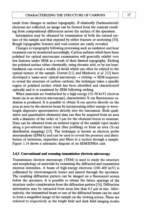
When materials are bombarded by a high-energy (10-50 keY) electron beam (as in an electron microscope), characteristic X-ray fluorescence radiation is produced. It is possible to obtain X-ray spectra directly on the area as seen by the electron beam by incorporating either energy or wavelength dispersive spectrometers directly into the instrument. Both qualitative and quantitative elemental data can thus be acquired from an area with a diameter of the order of 3 ~m for the elements boron to uranium. Data can be obtained from an isolated region of the sample (spot mode) along a pre-selected linear trace (line profiling) or from an area (X-ray distribution mapping) [13]. The technique is known as electron probe microanalysis (EPMA) and can be used to reveal the presence and distribution of inclusions, impurities and fillers in a section through a sample. Figure 1.14 shows a schematic diagram of an SEMIEPMA unit.
L4.3 Conventional and scanning transmission electron microscopy
Transmission electron microscopy (TEM) is used to study the structure and morphology of materials by examining the diffracted and transmitted electron intensities. A beam of high-energy electrons (100-400 ke V) is collimated by electromagnetic lenses and passed through the specimen. The resulting diffraction pattern can be imaged on a fluorescent screen below the specimen. It is possible to obtain the lattice spacings of the structure under consideration from the diffraction pattern [14]. Diffraction information may be extracted from areas less than 0.1 ~m in size. Alternatively, the transmitted beam or one of the diffracted beams can be used to form a magnified image of the sample on the viewing screen. These are referred to respectively as the bright field and dark field imaging modes

18 I I'-______ INTR __ O_D_U_CTI_O_N ______ _
Ap~rture ----X-ray detcectc)r ____ l'-..
Secondary elec:trnn-----''''-..: detector
Specimen chamber
coils
I-Cl'nrtc~n!;c~r lenses
~======~---Specimen stage
Fig. 1.14 Schematic diagram of a combined scanning electron microscopemicroprobe analyser.
and provide information about the size and shape of the microstructure of the material down to a resolution of around 0.2 nm.
By allowing the incident beam to raster over a predetermined area of the specimen and detecting said beam using a scintillator rather than a photographic plate, a scanning transmission electron microscopy (STEM) image is obtained on a television screen. The signal from the CRT may be further interfaced with a micro- or minicomputer allowing the performing of a number of advanced functions such as digital imaging, image enhancement and image analysis. Since the incident electron beam interacts with the specimen, characteristic X-rays will be emitted from the sample, which can be detected and analysed. The elemental composition for regions down to 0.05 Jlffi in size can be studied (Fig. 1.15).
To date, very few authors have published work describing TEM of carbon-carbon composites. This suggests that a serious gap exists in the microstructural knowledge of scientists working on the material; however, TEM provides access to a number of analytical techniques with extremely high spatial resolution and cannot be ignored if a complete understanding of the microstructural evolution of any material during processing is to be obtained. In the case of brittle fibrelbrittle matrix composites, such as carbon-carbon, TEM analysis should prove a particularly important aid to the understanding of the crucial fibre/matrix interface [15,16].
The major obstacle to effective TEM of carbon-carbon is simply one of specimen preparation. In order to employ TEM and associated techniques,

CHARACfERIZING THE STRUCTURE OF CARBONS I I 19 ~----------------------------------------------------~
D~o 0 0
Cathode ray tube & signal selector
LaB6 electron
gun
Secondary electron detector 6a r&l x-rays~
~
~ ~
~ IZI
Detector
Objective lenses
Specimen
} 1m.,;", I,", ",10m
Fig. 1.15 Schematic diagram of scanning transmission electron microscope with detection instrumentation.
specimens must be less than 100 nm thick, and preferably even thinner. Electron diffraction, high-resolution TEM (HREM) and analytical techniques such as energy dispersive X-ray analysis (EDX) and electron energy loss spectroscopy (EELS) require thin samples which are transparent to the electron beam, otherwise the large degree of scattering of the electrons which is possible in solid materials will impair the resolution by beam spreading. The interpretation of results obtained by the aforementioned techniques becomes increasingly difficult when transmitted electrons suffer multiple scattering events due to excessive specimen thickness. Books and papers covering the various techniques and information which they can give have been produced by a number of authors. In-depth and informative volumes have been published by Williams [14], Goodhew [17] and Loretto [18].
Carbonaceous materials are generally prepared by grinding or microtoming. Grinding a material has the obvious limitation that it is very difficult to relate the observed structure to the spatial arrangement of the original material by the time particles are small enough to be electron

20 I ~I _________________ ThIT ___ R_O_D_U_CTI __ O_N ________________ ~ transparent. Microtoming, the cutting of very thin slices, also results in mechanical disruption of regions of particular interest, such as the fibre/ matrix interface. A number of problems, such as lattice distortion, splitting, folding, microcracking and mechanical thinning, have been identified with these preparation techniques [19-22]. Microtomy has been successfully applied to the TEM of carbon fibres [19,23], which are generally embedded in an epoxy resin prior to slicing, thus considerably reducing the volume of brittle material to be cut. The skill and experience of the researcher can usually overcome the difference in mechanical response between resin and fibre. Unfortunately, the same cannot be said for carbon-carbon, where the fibre content may be very high (up to 70%), and the surrounding medium is very brittle.
One technique which can produce good-quality thin sections of carboncarbon is ion beam thinning or atom milling. The process involves lowenergy (5 keY) inert gas ions or atoms impinging at high velocity on the sample from both sides at low angles (between 10 and 450 to the plane of the sample). The process involves the slow removal of material from this surface. The rate of removal is of the order of a few microns of material per hour depending on material type and milling conditions. It is usually used, therefore, on samples which have first been mechanically thinned to around 50 J.UI1. Ion or atom milling is a relatively clean and gentle method. When examined, a material perforated in this way is a truer representation of the actual structure than that likely to be affected by mechanical thinning. Aside from the lack of speed, the main problems associated with milling are: implantation of the inert gas, heating of the specimen and the redeposition of sputtered material. The problems can be overcome or at least minimized by using a very low milling angle towards the completion of thinning and liquid nitrogen cooling of the specimen stage. The book by Goodhew [17] gives detailed descriptions of the techniques used to prepare TEM specimens. Kowbel and Don published a paper comparing microtomed and atom-milled bulk carbon produced from mesophase pitch [24]. They were able to show that a greater degree of damage resulted from microtomy and that this could lead to a misinterpretation of the microstructure. Numerous studies based on electron diffraction measurements of graphite crystallite size and orientation as a function of temperature have demonstrated the importance of TEM in the study of pyrolytic carbons, the results being summarized by Kowbel et al. [23].
Papers published with successfully thinned carbon samples highlight their complexity and demonstrate the importance of the interfaces between the various types of carbon present. These different types of carbon include the fibres (whether from rayon, polyacrylonitrile (PAN) or pitch precursors), the initial pyrolysis matrix and any carbon introduced for densification purposes (either by liquid impregnation or chemical vapour infiltration) [23-25]. The application of TEM to carbon-carbon systems will eventually

"--__ C_HA __ RA_CfE __ R_IZ_I_N_G_T_H_E_STR_U_CTU_R_E_O_F_C_A_RB_O_N_S __ -----ll I 21
be extended to the analysis of oxidation protection systems. Three basic methods of oxidation protection exist (see Chapter 6):
1. a surface coating of refractory material (often a multi-layer) protection; 2. glass-forming particulates included in the matrix to fill cracks which
may form in the surface coating as a result of thermal/mechanical cycling;
3. fibre coatings to prevent oxidation occurring preferentially at any exposed fibre/matrix interfaces.
In each case, the efficient operation of the protective system can be checked with the aid of TEM. At high temperatures the refractory additives are limited by reaction with the surrounding carbon. The extent of this carbothermal reduction will require TEM-associated and complementary techniques for a complete analysis of its microstructural effects.
1.4.4 X-ray diffraction
X-ray powder diffraction is used to obtain information about the average bulk structure of carbon materials. The technique provides a measure of the amount of ordered material present and can be used to give an indication of the size of the crystallites which make up the ordered structure. Samples are prepared as powders either in capillaries or spread on a flat sample holder. The minimum amount of material required is a few milligrams. Greater accuracy is achieved, however, if up to 1 g of the sample is available [26].
When a beam of monochromatic X-radiation is directed at a crystalline material, diffraction of the X-rays is observed at various angles with respect to the primary beam (Fig. 1.16). The relationship between the wavelength of the X-ray beam, A., the angle of diffraction, 2e, and the distance between each set of atomic planes of the crystal lattice, d, is given by the Bragg equation
n'A. = 2d sin 9, (1.7)
where n is the order of diffraction. Using this equation, the interplanar distances of the crystalline material under study can be calculated. The interplanar spacings depend solely on the arrangement of atoms in the crystal unit cell while the intensities of the diffracted rays are a function of both the diffracting power and the placement of the atoms within the unit cell [27].
The diffraction pattern obtained represents the amount of scattering over a range of scattering angles, 2e. The pattern can be considered as a 'fingerprint', each crystalline structure having, within limits, a unique diffraction pattern which can be analysed in terms of diffraction peaks, their positions and their widths. For the most accurate work, a standard

c=_~ c= __________________ INT __ R~O~D~U __ CT~I~O~N _____ ~ ____________ ~
Focusing Circle
r~\ ----r-\ ~~ \~~
D E
Fig. 1.16 Schematic diagram of an X-ray diffractometer. A, collimation assembly; B, sample; C. slit; D, exit beam monochromator; E, detector; X, source of X-rays.
compound, usually a highly crystalline salt, is added to the powder sample to afford internal calibration of the peak positions and widths, thus permitting any instrumental factors to be accounted for.
An indication of the degree of disorder within the specimen may be obtained since, although the principal scattering is due to the ordered material, the amount of background scatter may be analysed. Furthermore, the broadening of the diffraction peaks allows an estimation of the mean particle size to be made. The approximate crystallite size, t, can be calculated from the amount of broadening, ~, using the Scherrer equation
t = c",/~ cos 28, (1.8)
where c is the cell dimension, A the X-ray wavelength and 29 the scattering angle. ~ is the amount of broadening due to the sample. The observed broadening ~ requires to be corrected for the instrumental broadening b, generally using a relationship such as (Fig. 1.17)
(1.9)

t--__ C_HA_R_A_CfE __ RI_Z __ IN_G_THE __ S_T_R_U_CTU __ R_E_O_F_C_A_R_B_O_N_S __ ----'I I 23
B Specimen broadening
I'l-r-----t Instrument broadening
rument peak (estimated from highly crystalline standard J
Fig. L17 Line broadening in X-ray diffraction experiments.
The parameters most often quoted from X-ray diffraction experiments on carbon materials are:
d(002) Interlayer spacing of [002] planes Lc Stack height La Stack width
Small-angle scattering of X-rays and neutrons (SAXS and SANS) can be used to study the electron-density fluctuations and contrasts which exist over a range of 10-1000 A. It is, therefore, a useful technique with which to study the pore structure of carbons [28].
1.4.5 Surface analysis
A number of surface-sensitive techniques have been applied to carbon materials. The success of such techniques has unfortunately been somewhat limited because the extreme heterogeneity of the surfaces makes a full analysis as difficult as that of the bulk structures. Furthermore, all of the techniques require to be applied under high vacuum, making the in situ observation of surface changes, due to oxidation for example, impossible.
(a) X-ray photoelectron spectroscopy
X-ray photoelectron spectroscopy (XPS) or electron spectroscopy for chemical analysis (ESCA) [29] is used to provide information about the composition and structure of the outermost surface layers of a solid. When a solid is exposed to a flux of X-ray photons of known energy, photoelectrons are emitted from the solid. The photoelectrons originate from discrete electronic energy levels associated with those atoms in the analysis volume. The energy of the emitted photoelectrons is given by

24 I ~I __________________ INT __ R_O_D __ U_CT __ IO_N __________________ ~ (1.10)
where hv is the characteristic photon energy of the excitation source, EK and EB are the measured photoelectron energy and binding energy respectively of a specific core or valence-level electron and <1> is an experimental parameter depending on the spectrometer and sample being analysed. Ionization may occur, with varying probability, in any shell for a particular atom. The spectrum of that element is, therefore, usually comprised of a series of peaks corresponding to electron emission from the different energy levels. The energy separation and relative intensities of the peaks for a given element are well known, thus allowing unambiguous elemental identification. In addition, ESCA can be used to probe the electronic state of atoms so that the bonding configuration in the case of surface species can be determined which can, for example, reveal the difference between oxygen bound as atoms to the surface of the carbon in carbonyl or hydroxyl groups.
(b) Low-energy electron diffraction
Low-energy electron diffraction (LEED) patterns of single-crystal graphites have been obtained and used to study changes in the surface following treatments such as gasification. The technique is unfortunately very limited in application because only regular crystal surfaces can be observed with any acceptable degree of understanding.
(c) Auger electron spectroscopy
In Auger electron spectroscopy (AES) the excitation source is a finely focused electron beam which impinges on the sample surface. The two interactions of interest in AES and scanning Auger microscopy (SAM) are the generation of Auger electrons via the Auger process and the production of secondary electrons providing topographic information. The Auger process is initiated by electrons in the primary beam causing the ejection of core-level electrons from the atoms of the specimen. Once a core hole has been created, an electron from a higher energy level can fall into the core vacancy. Figure 1.18 illustrates the Auger process schematically in the form of an energy-level diagram. A transition of this type results in the release of energy by (a) the emission of characteristic X-rays or (b) the ejection of a second (Auger) electron.
The process in which a K shell ionization occurs followed by an L shell electronic transition which gives rise to an Auger electron ejected from an L shell is denoted a KLL transition. Similarly, transitions such as KLM and LMM may occur as shown in Fig. 1.18. Auger electrons are collected by the instrument's detection system which provides a display of the number

'--__ C_H_A_RA_Cf_E_R_I_Z_IN_G_T_H_E_S_T_R_V_C_T_V_R_E_O_F_C_A_R_B_O_N_S __ -----.JI I 25
LMM Augel [lectrllil
KLM Auger Electron
----+---+---~ :~1 M Shell
3s
KLL Auger Electron
---+----t---J 2P] L Shell
----~----~----2s
_____ ----'L...!-_______ 1 s K Shell Energy
Fig. 1.18 The Auger process.
of electrons N(E) vs their kinetic energy (KE) [30]. Auger spectra are generally displayed in the derivative mode dN(E) vs KE because of the relatively high secondary electron background count [31]. AES also provides information about the elemental and chemical composition of the sample. The major advantage of AES is in the small spot size of the electron beam probe which allows analysis of features of the sample beyond the spatial resolution of other surface techniques. Auger electron microscopy has been used to study carbon deposits on both single-crystal and polycrystalline metal surfaces. The inherently shallow sampling depth and high spatial resolution of AES allow its combination with ion beam milling for the analysis of a sample as a function of depth below the surface. This method may well prove important in assessing the performance

~ II ~ _________________ ThITR ___ O_D_U_CT __ IO_N ________________ ~ of mUlti-component oxidation protection systems for carbon-carbon materials.
1.5 DEFINITIONS OF CARBON FORMS AND PROCESSES
Carbon science is concerned with solid carbon materials, of which the overwhelming majority, with the exception of diamond, possess the basic structural arrangements of carbon atoms in a hexagonal planar array network. Carbon science and the carbon industry, in common with metallurgy, have their origins in antiquity. As a result, much of the nomenclature applied to the more 'modern' aspects of carbon science is derived from earlier work. It is appropriate, therefore, to define that terminology as used today since its use applies to all aspects of the subject. Solid carbons are generally derived from organic precursors by a pyrolysis process known as carbonization, and exist in graphitic and non-graphitic forms.
1.5.1 Carbonization
Carbonization is the process of formation of a material with increasing carbon content from an organic material, usually by pyrolysis, and ending with an almost pure carbon residue at temperatures over 1200 ·C.
1.5.2 Graphitization
Graphitization is the solid state transformation of metastable non-graphitic carbon into a graphite structure by thermal activation. The degree of graphitization depends upon the heat treatment temperature, the time allowed for rearrangement of the atoms and the applied pressure. Most graphitizable carbons pass through a fluid stage during the carbonization process.
1.5.3 Graphitic carbons
Graphite is the allotropic form of carbon consisting of layers of hexagonally arranged carbon atoms in a planar condensed ring system. Chemical bonds within the layers, which are stacked parallel to one another, are covalent with Sp2 hybridization. Bonding between the layers is relatively weak and of the van der Waals' type. Graphitic carbons are all varieties of material consisting of the element carbon in the allotropic form of graphite, irrespective of the presence of structural defects. Natural graphite is a mineral consisting of graphitic carbon regardless of its crystalline perfection. Some natural graphites show a high degree of perfection but most are mined in the form of flake graphites containing other mineral matter. Synthetic
L--__ D_E_F_I_N_IT_I_O_N_S_O_F_C_A_R_B_O_N_F_O_R_M_S_A_N_D_P_R_O_C_E_S_S_ES __ -------'I I 27
graphite is defined as a material consisting mainly of graphitic carbon which has been obtained by means of a graphitization heat treatment of a non-graphitic carbon or by chemical vapour deposition (CVD) from hydrocarbons at temperatures above 1800 ·C to give a deposit with the graphite structure.
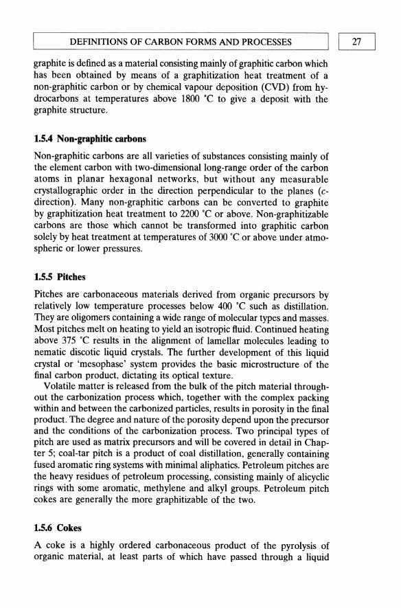
1.5.4 Non-graphitic carbons
Non-graphitic carbons are all varieties of substances consisting mainly of the element carbon with two-dimensional long-range order of the carbon atoms in planar hexagonal networks, but without any measurable crystallographic order in the direction perpendicular to the planes (cdirection). Many non-graphitic carbons can be converted to graphite by graphitization heat treatment to 2200 ·C or above. Non-graphitizable carbons are those which cannot be transformed into graphitic carbon solely by heat treatment at temperatures of 3000 ·C or above under atmospheric or lower pressures.
1.5.5 Pitches
Pitches are carbonaceous materials derived from organic precursors by relatively low temperature processes below 400 ·C such as distillation. They are oligomers containing a wide range of molecular types and masses. Most pitches melt on heating to yield an isotropic fluid. Continued heating above 375 ·C results in the alignment of lamellar molecules leading to nematic discotic liquid crystals. The further development of this liquid crystal or 'mesophase' system provides the basic microstructure of the final carbon product, dictating its optical texture.
Volatile matter is released from the bulk of the pitch material throughout the carbonization process which, together with the complex packing within and between the carbonized particles, results in porosity in the final product. The degree and nature of the porosity depend upon the precursor and the conditions of the carbonization process. Two principal types of pitch are used as matrix precursors and will be covered in detail in Chapter 5; coal-tar pitch is a product of coal distillation, generally containing fused aromatic ring systems with minimal aliphatics. Petroleum pitches are the heavy residues of petroleum processing, consisting mainly of alicyclic rings with some aromatic, methylene and alkyl groups. Petroleum pitch cokes are generally the more graphitizable of the two.
1.5.6 Cokes
A coke is a highly ordered carbonaceous product of the pyrolysis of organic material, at least parts of which have passed through a liquid
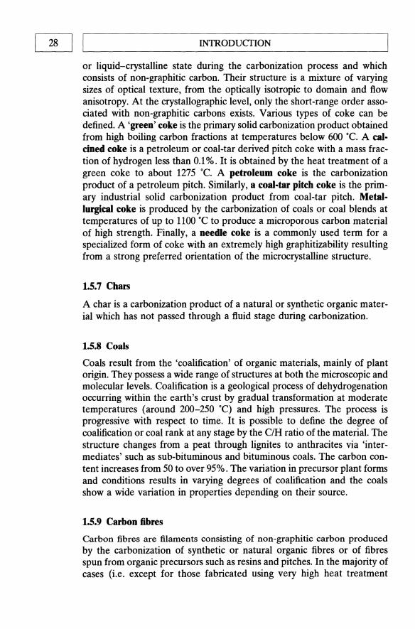
~ 1~ _______________ ThITR ___ O_D_U_CT_I_O_N ______________ ~ or liquid-crystalline state during the carbonization process and which consists of non-graphitic carbon. Their structure is a mixture of varying sizes of optical texture, from the optically isotropic to domain and flow anisotropy. At the crystallographic level, only the short-range order associated with non-graphitic carbons exists. Various types of coke can be defined. A 'green' coke is the primary solid carbonization product obtained from high boiling carbon fractions at temperatures below 600°C. A calcined coke is a petroleum or coal-tar derived pitch coke with a mass fraction of hydrogen less than 0.1 %. It is obtained by the heat treatment of a green coke to about 1275 0C. A petroleum coke is the carbonization product of a petroleum pitch. Similarly, a coal-tar pitch coke is the primary industrial solid carbonization product from coal-tar pitch. Metallurgical coke is produced by the carbonization of coals or coal blends at temperatures of up to 1100 °C to produce a microporous carbon material of high strength. Finally, a needle coke is a commonly used term for a specialized form of coke with an extremely high graphitizability resulting from a strong preferred orientation of the microcrystalline structure.
1.5.7 Chars
A char is a carbonization product of a natural or synthetic organic material which has not passed through a fluid stage during carbonization.
1.5.8 Coals
Coals result from the 'coalification' of organic materials, mainly of plant origin. They possess a wide range of structures at both the microscopic and molecular levels. Coalification is a geological process of dehydrogenation occurring within the earth's crust by gradual transformation at moderate temperatures (around 200-250 0c) and high pressures. The process is progressive with respect to time. It is possible to define the degree of coalification or coal rank at any stage by the CIH ratio of the material. The structure changes from a peat through lignites to anthracites via 'intermediates' such as sub-bituminous and bituminous coals. The carbon content increases from 50 to over 95%. The variation in precursor plant forms and conditions results in varying degrees of coalification and the coals show a wide variation in properties depending on their source.
1.5.9 Carbon fibres
Carbon fibres are filaments consisting of non-graphitic carbon produced by the carbonization of synthetic or natural organic fibres or of fibres spun from organic precursors such as resins and pitches. In the majority of cases (i.e. except for those fabricated using very high heat treatment

I I 29 L-__________________________________________________ ~ CARBON COMPOSITES
temperatures (>2700 0c) the fibres remain as non-graphitic carbon, contrary to the nomenclature often used in the United States! The alignment of the lamellar planes along the fibre axes exploits the anisotropic properties of carbon materials. There are three principal types of carbon fibre: those based on PAN, rayon and mesophase pitch. All will be considered in greater detail in Chapter 2.
1.S.10 Deposited carbons
Chemical vapour deposition of carbon from volatile hydrocarbon compounds on to carbon, metal or ceramic substrates provides a processing route to obtain carbon materials with a homogeneous microstructure. The method is used extensively in the densification of carbon-carbon composites and is reviewed in Chapter 3. When the substrate is an active catalyst for carbon deposition, the growth of whiskers or filaments by a solution/deposition mechanism, with small metal particles at the tip, has been observed. Such filaments are often highly graphitic [32].
1.5.11 Other 'misceUaneous' forms of carbon
Charcoal is a traditional term used for a char obtained from wood and certain related natural organic materials. The form of the parent material is retained, often with a highly developed pore structure. At the microscopic level the basic structure is disordered, producing an isotropic optical texture. The crystallographic-level structure also exhibits very little order with no detectable graphitic properties. Carbon blacks are produced by vapour phase growth of particles which are, on the whole, spherical with no regular long-range order. Some carbon blacks are the closest approach to a truly 'amorphous' carbon. Activated carbons are porous carbon materials, usually chars, which have been subjected to reaction with gases either during or after carbonization with the purpose of increasing their microporosity. The degree and type of porosity may be controlled to provide materials with large and, if required, specific adsorption capacity. Such materials are widely used as filters and catalyst supports, etc.
1.6 CARBON COMPOSITES
Composites are best defined as materials in which two or more constituents have been brought together to produce a new material nominally, at least, of more than one component, with resultant properties different from those of the individual constituents. The carbon materials thus far defined, although heterogeneous in nature, are all homogeneous in terms

30 I LI _________________ INT __ R_O_D_U_CT __ IO_N ________________ ~ Porosity
Binder carbon
Filler particles
Fig. 1.19 Schematic representation of the microstructure of particulate carbon composites.
of treatment. One of the most critical aspects determining the nature and properties of a composite material is the interfaces between components. The strength of the composite is often governed by the adhesion forces which can be chemical, physical or a combination of the two.
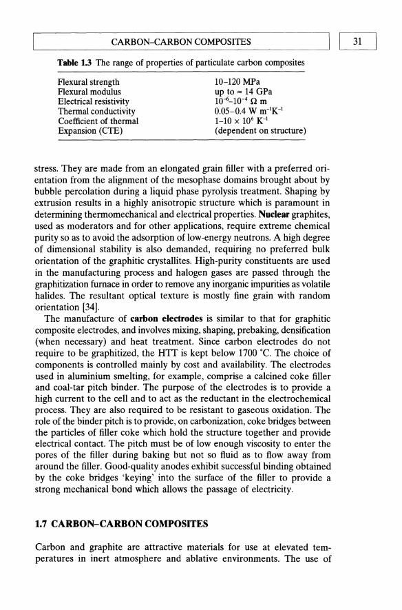
The great majority of the industrial engineering carbons and graphites fall into the category of particulate filled composites. They are manufactured by a process in which a carbon filler is bonded with a liquid organic precursor, shaped, carbonized and, if so desired, graphitized up to 2700"C. The filler phase is generally some form of graphitizable coke produced by a liquid phase pyrolysis route. The binder is either a resin, such as a phenolic or furan, or a pitch. Both graphitizable and non-graphitizable binders can, therefore, be used although pitch is most often employed. A wide range of particulate carbon composites may thus be produced by the variation in the size distribution of the filler particles, the types of filler and binder, the binder content and the heat treatment temperature (HTT) [33]. Figure 1.19 shows a general schematic microstructure for this family of composites. The materials are porous, although the porosity may be significantly reduced, if required, by reimpregnation with pitch or resin binder followed by recarbonization. The porosity is a result of that in the original filler, that developed due to shrinkage of the binder during carbonization and voidage due to inefficient impregnation by the binder. Carbon composites of this type, whose properties are listed in Table 1.3, are widely used in a number of important applications.
Graphite electrodes may be enormous structures when, for example, used for the production of steel in electric arc furnaces. They are highly graphitic, exhibiting an isotropic optical texture, and are capable of carrying a heavy electrical current at high temperatures under large thermal
L-__________ C_A_RB __ O_N_-_C_A_RB __ O_N_C_O_MP __ O_S_ITE __ S __________ ~I I 31
Table 1.3 The range of properties of particulate carbon composites
Flexural strength Flexural modulus Electrical resistivity Thermal conductivity Coefficient of thermal Expansion (CTE)
10-120 MPa up to '" 14 GPa 10-6_10-4 Q m 0.05-0.4 W m-1K-1
1-10 x 106 K-1
(dependent on structure)
stress. They are made from an elongated grain filler with a preferred orientation from the alignment of the mesophase domains brought about by bubble percolation during a liquid phase pyrolysis treatment. Shaping by extrusion results in a highly anisotropic structure which is paramount in determining thermomechanical and electrical properties. Nuclear graphites, used as moderators and for other applications, require extreme chemical purity so as to avoid the adsorption of low-energy neutrons. A high degree of dimensional stability is also demanded, requiring no preferred bulk orientation of the graphitic crystallites. High-purity constituents are used in the manufacturing process and halogen gases are passed through the graphitization furnace in order to remove any inorganic impurities as volatile halides. The resultant optical texture is mostly fine grain with random orientation [34].
The manufacture of carbon electrodes is similar to that for graphitic composite electrodes, and involves mixing, shaping, prebaking, densification (when necessary) and heat treatment. Since carbon electrodes do not require to be graphitized, the HTT is kept below 1700 dc. The choice of components is controlled mainly by cost and availability. The electrodes used in aluminium smelting, for example, comprise a calcined coke filler and coal-tar pitch binder. The purpose of the electrodes is to provide a high current to the cell and to act as the reductant in the electrochemical process. They are also required to be resistant to gaseous oxidation. The role of the binder pitch is to provide, on carbonization, coke bridges between the particles of filler coke which hold the structure together and provide electrical contact. The pitch must be of low enough viscosity to enter the pores of the filler during baking but not so fluid as to flow away from around the filler. Good-quality anodes exhibit successful binding obtained by the coke bridges 'keying' into the surface of the filler to provide a strong mechanical bond which allows the passage of electricity.
1.7 CARBON-CARBON COMPOSITES
Carbon and graphite are attractive materials for use at elevated temperatures in inert atmosphere and ablative environments. The use of

32 II ~ _______________ ThITR ___ O_D_U_CTI __ O_N ______________ ~ 50~--------------------------~
40
~ 30 E E
.,,~
o .-x :>.. .... . ~ 20 "0 ...... V) I::::>
10
Titanium 35 '10 SiC fibres(OOonly)
y , , " 35 % B .. C(Particulate)/Ti
',I , Titanium ...... , 35 ~o B .. C
___ ____ ~'- (Particulate)/nickel
'~,,( \
Nicke l.-=:;;;~;~~~~~::::~(~a~rb~o~n~-~ca~r=b=o=n::::::::::::l _ (-Si(
Si(- SiC
Colu mbium(Niobi u m)C129Y
O+---~--~~--~--~--~--~--~--~
o 400 800 1200 1600 Tempera ture(K)
Fig. 1.20 Strength to density ratio for different classes of high-temperature materials with respect to temperature.
monolithic carbon or particulate composites is greatly limited by brittle mechanical behaviour, flaw sensitivity, variability in properties, anisotropy and fabrication difficulties associated with large and complex components and structures [35]. Carbon fibre reinforced carbon matrix composites consist of carbon fibres embedded in a carbonaceous matrix. The aim of these materials is to combine the advantages of fibre-reinforced composites such as high specific strength, stiffness and in-plane toughness with the refractory properties of structural ceramics [36]. A retention of mechanical properties at high temperatures, superior to any other material (Fig. 1.20) has resulted in the exploitation of carbon-carbon composites as structural materials in space vehicle heat shields, rocket nozzles and aircraft brakes. Additionally, properties such as biocompatibility and

L-______ C_A_RB_O_N_-_C_A_RB_O_N_C_O_M_P_O_S_IT_E_S ______ ---.JI I 33
chemical inertness have led to new applications in medicine and industry. Carbon--carbon composites can perhaps lay claim to represent the ultimate development of carbon science.
Although carbon composites, in the form of polygranular synthetic graphite, were used in the fins of Second World War German rockets [37], it was not until the advent of carbon fibre technology in the late 1950s that the potential for the development of truly structural components was realized.
The advancement of carbon-carbon composite materials technology was initially very slow, but by the late 1960s it had begun to emerge as a major new genre of engineering materials [38,39]. During the 1970s, carboncarbon structures were under extensive development in the USA and Europe [40-45], mainly for military use. The original carbon-carbon composites, to be used in rocket nozzles and re-entry parts, were produced using reinforcements in the form of woven fabrics of low-modulus rayon precursor carbon fibres. The matrix was derived from pyrolysed high-char yield resins such as phenolic and furan. Fibre-reinforced plastic moulding techniques were used to fabricate precursor composite structures which were subsequently carbonized.
Since those early days, it is now possible to use the whole variety of available types of carbon fibres (see Chapter 2) with their individual characteristics. The fibres may be combined in a wide variety of woven, 'knitted', braided and filament wound forms to provide one-, two- and multi-directional reinforced composites. Additionally, lower-cost composites employ a wide range of felts, fabric and short fibre systems. The reinforcing fibres can be combined with any of the forms of carbon, previously described. The matrix, for example, could be a vapour-deposited carbon, a glassy carbon (resulting from the pyrolysis of a resin) or the coke from the liquid phase pyrolysis of a mesophase pitch. Furthermore, by careful control of the precursor and the HTT, the degree of graphitization of the matrix may be varied considerably, thus imparting a wide range of thermomechanical properties to the composite. Carbon-carbon is not, therefore, a single material, but rather, a family of materials, many combinations of which have yet to be realized and evaluated. To some extent carbon-carbon composites resemble the particulate carbon composites, save that the granular filler is replaced by fibres. The characteristics of the precursors and the processes which take place during manufacture are critical in determining the ultimate properties.
There are two key developments required in order to secure a more widespread deployment of carbon-carbon. Many possible markets are severely limited as a result of the excessive costs of the composites. If carbon--carbon is to be exploited in cost-sensitive applications such as replacement of asbestos in motor vehicle and passenger train brakes, more efficient and economically viable precursors and processes need to be
34 I LI __________________ INTR ___ O_D __ U_CT __ IO_N __________________ ~ developed. In very 'high technology' usage, where cost is justified by improved performance (such as aircraft engine parts), prevention of oxidation is the paramount concern. Furthermore, a number of less critical, but still significant problems such as poor matrix mechanical properties, for example, need to be addressed.
To address the aforementioned problems, we are required to move away from carbon-carbon in isolation to define and develop what are described as materials systems. We first define a primary function of the material such as retention of strength at high temperatures, which is accomplished by carbon-carbon. The environment in which the material is required to operate will dictate a number of secondary functions/properties before any component can perform successfully. In order to impart attributes such as oxidation stability, fatigue resistance and 'out of plane toughness', it will be necessary to combine the 'basic' composite with a number of other compounds such as oxidation-protective coatings and matrix additives and develop a materials system capable of meeting all of the requirements.
REFERENCES
1. Int. Bur. Stds (1961). 2. Franklin, R. E. (1951) Acta Cryst. 4,253. 3. Griffiths, J. A. and Marsh, H. (1981) Proc. 15th Biennial Con! on Carbon,
University of Pennsylvania, Philadelphia, USA, 22-26 June. 4. Cornford, C., Forrest, R. A., Kelly, B. T. and Marsh, H. (1984) in Chemistry
and Physics of Carbon, 19 (ed. P. A. Thrower), Marcel Dekker, New York, p.211.
5. Spencer, M. (1982) Fundamentals of Light Microscopy, Cambridge University Press, Cambridge, UK.
6. Jenkins, G. M. and Kawamura, K. (1976) Polymeric Carbons, Carbon Fibre, Glass and Char, Cambridge University Press, London.
7. Fischmeister, H. (1981) Digital image analysis in quantitative metallography, in Computers in Materials Technology, Pergamon Press, New York, pp. 109-29.
8. Van der Voort, G. F. (1986) Image analysis, in Metals Handbook, 9th end, Vol. 10, Materials Characterization, American Society for Metals, Metals Park, pp.309-22.
9. Goldstein, J., Yakowitz, H., Newbury, D., Lifshin, E., Colby, J. and Coleman, J. (1975) Practical Scanning Electron Microscopy, Plenum Press, New York.
10. Wells, O. C. (1974) Scanning Electron Microscopy, McGraw-Hill, New York. 11. Forest, M. A. and Marsh, H. (1981) Proc. 15th Biennial Con! on Carbon,
University of Pennsylvania, Philadelphia, USA, 22-6 June. 12. Markovic, V., Ragan, S. and Marsh, H. (1984) 1. Mat. Sci., 19, 3287. 13. Heinrich, K. F. (1981) Electron Beam X-ray Microanalysis, Van Nostrand
Reinhold Company, New York.

~ _________________ RE __ F_E_RE __ N_C_E_S ________________ ~I I 35
14. Williams, D. B. (1984) Practical Analytical Electron Microscopy, Phillips Electronic Instruments Publishing, Mahwah, New Jersey.
15. Peebles, L. H. Meyer, R. A. and Jortner, J. (1988) in Interfaces in Polymer, Ceramic and Metal Matrix Composites (ed. H. Ishida), Elsevier, Amsterdam, p. 1.
16. Evans, A. G. and Thonless, M. D. (1988) Acta Metall., 36, 517. 17. Goodhew, P. J. (1985) Practical Methods in Electron Microscopy, Vol. II,
Elsevier, Oxford. 18. Loretto, M. H. (1984) Electron Beam Analysis of Materials, Chapman and Hall,
London. 19. Bennet, S. C. and Johnson, D. J. (1979) Carbon, 17, 25. 20. Tidjani, M. (1986) Carbon, 24, 447. 21. Shiraishi, M. (1978) 1. Mat. Sci., 13, 702. 22. Ehrburger, P. and Lahaye, J. (1981) Carbon, 19, 1. 23. Kowbel, W., Hippo, E. and Murdie, N. (1989) Carbon, 27, 219. 24. Kowbel, W. and Don, J. (1987) Proc. 18th Biennial Con! on Carbon,
Worcester, Mass., 19-24 July 1987, p. 286. 25. Weizhou, P., Tianyon, P., Hansin, Z. and Qias, Y. (1988) in Interfaces in
Polymer, Ceramic and Metal Matrix Composites, (ed. H. Ishida), Elsevier, Amsterdam.
26. Azaroff, L. V. (1968) Elements of X-ray Crystallography, McGraw-Hill, New York.
27. Klug H. P. and Alexander, L. E. (1974) X-ray Diffraction Procedures for Polycrystalline and Amorphous Materials, Wiley, New York.
28. Glatter, O. and Kratky, O. (1982) Small-angle X-ray Scattering, Academic Press, New York.
29. Briggs, D. (ed.) (1972) Handbook of X-ray and Ultraviolet Photoelectron Spectroscopy, Heyden Press, London.
30. Carlson, T. A. (1975) Photoselection and Auger Spectroscopy, Plenum Press, New York.
31. Spruger, R. W., Haas, T. W., and Grant, J. T. (1978) Quantitative Surface Analysis of Materials, ASTM STP 634, American Society for Testing and Materials, Philadelphia.
32. Tibbetts, G. G. (1989) Carbon, 27(5), 745. 33. Rand, B. (1989) Proc. HIPERMAT 89 Con!, City Conference Centre, I.
Marine Eng., London, 27-28 Sept. 1989. 34. Kelly, B. T. (1981) Physics of Graphite, Applied Science Publishers, London. 35. Fabrication of composites, in Handbook of Composites, (1986) Vol. 4 (eds A.
Kelly and S. T. Mileiko North-Holland, pp. 111-75. 36. Savage, G. M. (1988) Metals and Materials, 4, 544. 37. Vohler, O. and Fitzer, E. (1961) lahrbuch der Wissenschaftlichen Gesellschaft
fur Luftfahrt e.v. WGL, pp. 467-73, Munich. 38. Schmidt, D. L. (1972) SAMPE 1.,8, 9. 39. Frye, E. R. and Stoller, H. M. (1969) Proc. AIANAIME 10th Structures,
Structural Dynamics and Materials Conf., New Orleans, p. 193. 40. McAllister, L. E. and Taverna, A. R. (1976) Proc. Int. Con! on Composite
Materials, Vol. 1, Met. Soc. of AIME, New York, p. 307.

36 I 1~ ______________ ThITR ___ O_D_U_CTI __ O_N ______________ ~ 41. Fitzer, E. and Burger, A. (1971) Int. Cont on Carbon Fibres, their Composites
and Applications, London paper no. 36. 42. Lamieq, P. (1977) Proc. AIAAlSAE 13th Propulsion Cont, Paper no. 77-882,
Orlando. 43. Fitzer, E., Geigle, K. H. and Huttner, W. (1978) Proc. 5th London Int. Carbon
and Graphite Cont, Vol. 1, p. 493. 44. Girard, H. (1978) Proc. 5th London Int. Carbon and Graphite Cont, Vol. 1 (Soc.
Chern. Ind. London), p. 483. 45. Thomas, C. R. and Walker, E. J. (1978). Proc. 5th London Int. Carbon and
Graphite Con/., Vol. 1 (Soc. Chern. Ind. London), p. 520.

~ ____ c __ ar_b_o_n_F_i_b_re_s ____ ~I~
2.1 INTRODUCTION
The measured strengths of materials are several orders of magnitude less than those calculated theoretically. This discrepancy is believed to be due to the presence of inherent flaws within the material [1]. It follows that the strength of a material can therefore be enhanced by eliminating or minimizing such imperfections. Cracks lying perpendicular to the direction of applied loads are the most detrimental to the strength. Fibrous or filamentary materials thus exhibit high strengths and moduli along their lengths because in this direction the large flaws present in the bulk are minimized.
Fibres readily support tensile forces, but alone will offer virtually no resistance and buckle under compression. In order to be directly usable in engineering applications they must be embedded in matrix materials to form fibrous composites. The matrix serves to bind the fibres together, transfer loads to the fibres and protect them against handling damage and environmental attack. Fibre-reinforced composite materials are generally fabricated to improve mechanical properties such as strength and toughness per unit weight, although protective applications such as vehicle armour are gaining in significance [2]. Carbon-carbon composites are usually produced in order to exploit their retention of properties at very high temperatures [3].
Composites can be divided into two classes: those with long fibres (continuous fibre-reinforced composites) and those with short fibres (discontinuous fibre-reinforced composites). In a discontinuous fibre composite, the material properties are affected by the fibre length, whereas in a continuous fibre composite it is assumed that the load is transferred directly to the fibres and that the fibres in the direction of the load are the principal load-bearing constituent.
The most common matrices for fibre-reinforced composites are polymeric materials which may be subdivided into two distinct types: thermosetting and thermoplastic. Thermosetting polymers are resins which crosslink during
38 I LI _________________ C_A_R_B_O_N_fl __ B_RE __ S ________________ ~ curing into a glossy, brittle solid (examples are polyesters, vinylesters and epoxies). Thermoplastic polymers are high-molecular-weight, long-chain molecules which can either become entangled (amorphous), for example polycarbonate, or partially crystalline, such as nylon and polyetheretherketone (PEEK), at room temperature to give strength and shape. Crystalline thermoplastic systems offer enhanced environmental resistance, creep resistance and toughness at the expense of increased cost and difficulties in processing.
Designers of weight-sensitive structures such as aircraft and racing cars require materials which combine good mechanical properties with low weight. Aircraft originally employed wood and fabric in their construction, but over the last 50 years aluminium alloys have been the dominant materials. During the last decade advanced composite materials have been increasingly employed for certain aircraft structures. At this point it is appropriate to define what has become a 'buzz-word' in the composites industry, the term 'advanced'; an advanced composite is simply one in which the mechanical properties are dominated by the fibres. The composites used in aircraft applications have been mainly those based on continuous carbon fibres and to a lesser extent glass and aramid. The use of composites in Formula 1 racing cars is far more widespread, such that the whole structure is normally of carbon fibre reinforced composite (Fig. 2.1).
The driving force for the increasing substitution of metals by composite materials is demonstrated in Table 2.1. Although the strengths and stiffnesses are not very different from those of metals, their densities are much lower, hence composites have greatly improved specific properties. The weight savings obtained in practice are not as great as Table 2.1 implies because the fibre composites are anisotropic and this must be accounted for in any design calculations. Even so, savings in weight of around 30% are readily achieved over aluminium [4,5]. An increasing number of applications, such as re-entry components and rocket nozzles, demand higher and higher operating temperatures. Metals creep at such temperatures and polymeric composites decompose, thus rendering them useless. Carbon fibres on the other hand, provided they are protected from oxidation, are shown to retain their properties to temperatures well in excess of 2000 0c. It is logical therefore to develop carbon fibre/carbon matrix composites in order to solve the problems of high-temperature operation. Since carbon fibres form a major part of carbon-carbon composites, and to a great extent control their mechanical properties, it is important to review their production, properties and processing so that their interaction within the composites may be more clearly understood.
In Chapter 1 it was discussed how the element carbon has two lowdensity allotropes, graphite and diamond. Both forms exhibit strong covalent bonding between the carbon atoms. Graphite has a hexagonal structure in which the strong Sp2 hybrid bonding within the hexagonal-layer planes generates the highest absolute and specific moduli and theoretical tensile

INTRODUCTION I I 39 L-____________________________________________________ ~
Rear Wing Assy
-"" '- Sidepod
Front Wing Assy
Fig.2.1 The Williams FW14 Formula 1 racing car showing its composite components. (By kind permission of Brian O'Rourke. Williams Grand Prix Engineering Ltd.)
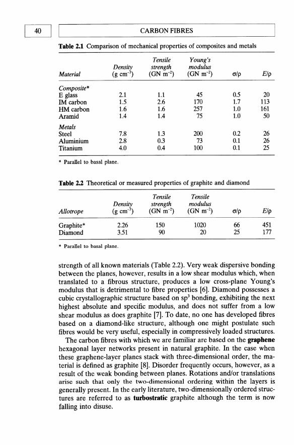
40 I I CARBON FIBRES
Table 2.1 Comparison of mechanical properties of composites and metals
Tensile Young's Density strength modulus
Material (g cm-3) (GN m-2) (GN m-2) alp Elp
Composite* E glass 2.1 1.1 45 0.5 20 1M carbon 1.5 2.6 170 1.7 113 HM carbon 1.6 1.6 257 1.0 161 Aramid 1.4 1.4 75 1.0 50
Metals Steel 7.8 1.3 200 0.2 26 Aluminium 2.8 0.3 73 0.1 26 Titanium 4.0 0.4 100 0.1 25
* Parallel to basal plane.
Table 2.2 Theoretical or measured properties of graphite and diamond
Tensile Tensile Density strength modulus
Allotrope (g cm-3) (GN m-2) (GN m-2) alp Elp
Graphite * 2.26 150 1020 66 451 Diamond 3.51 90 20 25 177
* Parallel to basal plane.
strength of all known materials (Table 2.2). Very weak dispersive bonding between the planes, however, results in a low shear modulus which, when translated to a fibrous structure, produces a low cross-plane Young's modulus that is detrimental to fibre properties [6]. Diamond possesses a cubic crystallographic structure based on Sp3 bonding, exhibiting the next highest absolute and specific modulus, and does not suffer from a low shear modulus as does graphite [7]. To date, no one has developed fibres based on a diamond-like structure, although one might postulate such fibres would be very useful, especially in compressively loaded structures.
The carbon fibres with which we are familiar are based on the graphene hexagonal layer networks present in natural graphite. In the case when these graphene-Iayer planes stack with three-dimensional order, the material is defined as graphite [8]. Disorder frequently occurs, however, as a result of the weak bonding between planes. Rotations and/or translations arise such that only the two-dimensional ordering within the layers is generally present. In the early literature, two-dimensionally ordered structures are referred to as turbostratic graphite although the term is now falling into disuse.

L-__________ P_R_O_C_E_SS_m __ G_O_F_C_A_RB __ O_N_F_I_B_RE_S __________ ~I I 41
Another gross misnomer whose use persists, much beloved by the advertising industry, is the improper application of the term 'graphite fibres' to carbon fibres which have only two-dimensional ordering.
Carbon fibres offer the highest modulus and highest strength of all reinforcing fibres. The fibres are not susceptible to stress corrosion or stress rupture failures at room temperature unlike glass and polymeric fibres. Ongoing process development work promises significant improvements in the ratio of performance/cost which would greatly increase the use and applications of these fibres.
2.2 PROCESSING OF CARBON FIBRES
2.2.1 Historical
Carbon fibres have been produced inadvertently from natural cellulosic fibres such as cotton or linen for millennia. The first recorded purposeful transformation of cellulose to carbon fibres was by Thomas Edison in 1878. Edison converted cotton and later, bamboo strips, into carbon for use as filaments in incandescent electric lamps [9]. After 1910, the lamp industry changed to the use of tungsten filaments so that the production of carbon filaments was terminated.
Interest in carbon fibres was renewed in the late 1950s with the advent of jet propulsion which precipitated the development of faster and larger aircraft. Laboratory tests on graphite whiskers uncovered strength values of 20 GPa and a modulus of 1000 GPa. Mechanical properties of this magnitude represented a 30-fold increase in specific tensile strength and a 17-fold improvement in specific modulus over the structural metals such as steel, aluminium and titanium [10]. Under sponsorship from the USAF, the Union Carbide Company fabricated carbon fibres in a similar way to Edison save that they used a rayon precursor. Two types of fibre were produced: the VIB type were treated to carbonization temperatures of around 1000 ·C whereas the WYB type were post heat treated to 'graphitization' temperatures in excess of 2200 ·C [11]. The fibres retained the fibrous structure of their rayon precursors but were isotropic as defined by their X-ray diffraction pattern. It is possible that the incorrect term 'graphite fibres' was introduced at that time in order to make a distinction between the WYB fibres which were pure carbon, as a result of high temperature heat treatment, and the VIB type which still contained many heteroatoms such as oxygen, hydrogen and ash-forming residues.
During the 1960s Union Carbide were able to demonstrate that hot stretching of the fibres at the highest temperatures (>2200 .C) resulted in higher modulus fibres. A number of contributory factors, such as the plastic deformability of solid carbon, the fibrillar structure of the rayon and the

42 I LI _________________ C_A_R_B_O_N_F_I_B_R_E_S ________________ ~ high degree of porosity within the fibres, resulted in a high degree of elongation during the high-temperature processing. Elongations of up to 100% produced a strong preferred orientation within the fibres such that tensile moduli of up to 500 GPa were achieved. The fibres were released commercially under the trade name Thornel25, 50 and 70, the numerical postscripts indicating the modulus in Msi.
In parallel with the work at Union Carbide, Shindo and co-workers in Japan were investigating polyacrylonitrile (PAN) as a possible precursor [12]. Despite ex-rayon fibres being the first produced in quantity [13] it was soon demonstrated that PAN was a superior starting material [14,15]. The PAN precursor increased in importance as a result of the effort of English workers sponsored by the Royal Air Force at RAE Farnborough [16,17]. Watt et al. showed that high-strength fibres could be obtained by oxidizing the PAN precursor while under strain without the need for a hot-stretching stage after carbonization.
All of the continuous carbon fibres produced to date have begun with organic precursors which were subsequently pyrolysed. Discontinuous carbon whiskers have been produced by vapour-liquid-solid (VLS) growth from an iron catalyst and a hydrocarbon gas [18,19]. High-modulus (HM) carbon fibres (>200 GPa) require the stiff graphene layers to be aligned approximately parallel to the fibre axis. The low shear modulus between the planes significantly decreases the fibre stiffness for any off-axis layers. Commercial carbon fibre processes develop the required orientation by plastic deformation. The preferred orientation, which can be introduced into the precursor fibres, will be retained, at least in part, upon conversion to carbon [20-22]. Axial alignment may also be developed into the fibre by high-temperature deformation [23].
The carbon fibre industry presently uses three different precursor materials: rayon and PAN fibres and pitch, either isotropic or liquid crystalline (mesophase). Rayon and isotropic pitch precursors are used to produce low modulus fibres «60 GPa) [24-27]. Fibres from both types of precursor can be strained at high temperatures to increase their moduli substantially but the process is not operated commercially to date [23,25]. Higher-modulus fibres are made from PAN or mesophase pitch precursors. In both cases an oriented precursor fibre is spun, stabilized by slightly oxidizing to thermoset the fibres and carbonizing to temperatures in excess of 800 ·C [20-22,28] to produce a carbon fibre. The fibre modulus increases with heat treatment temperature (HIT) from 1000 to 3000 ·C although the relationship between modulus and HIT is non-uniform, depending very much on the precursor [6,17]. The tensile strength of all PAN-based fibres, and a number of those from mesophase pitch, more often than not maximizes at an intermediate temperature of around 1500 .c. This is due to the formation of intrafibrillar porosity at HIT > 1500 ·C in PAN materials, the so-called 'Reynolds-sharp cracks' [10]. The majority

L-__________ P_R_O_C_E_S_S_IN_G __ O_F_C_A_R_B_O_N_F_I_B_R_ES __________ ~I I 43
of mesophase pitch precursor fibres continuously increase their strength with increasing HIT.
2.2.2 Rayon-based carbon fibres
Figure 2.2 shows the basic elements required for producing carbon filaments from rayon [10]. The first low-temperature treatment takes place typically at around 300 ·C and converts the structure to a form which is stable to higher processing temperatures. The process involves polymerization and the formation of cross-links. The rayon may be subjected to a chemical treatment before the first-stage oxidation exposure. The chemical bath can be an aqueous ammonium chloride solution or a dilute solution of phosphoric acid in denatured ethanol. The chemical treatment serves to reduce the time for the low-temperature step from several hours to around 5 minutes. Of the fibre mass, 50-60% is lost to decomposition products such as H20, CO and CO2 during oxidation. The carbonization step, resulting in further weight loss, is usually carried out at ",1500 ·C. The yield after carbonization is typically 20-25% of the original polymer weight. At this stage the fibres have an essentially isotropic structure. The mechanical properties of carbonized rayon are poor as a direct result of the poor alignment of the graphene layers. Stretching of the fibres during heat treatment to graphitization temperatures significantly increases both strength and modulus, but is an expensive process. The morphology of the ex-rayon carbon fibres exhibits a crenulated surface, rather like a stick of celery, which is derived from the original precursor (Fig. 2.3). The combination of poor mechanical properties, low carbon yield and expense of graphitization has meant that ex-rayon carbon fibres have generally not proved competitive in the market place, although they are used extensively in ablative technology. This is due to their poor through thickness thermal conductivity and because their composites yield high inter laminar shear strengths. Table 2.3 lists typical rayon-based carbon fibre properties. A full review of the conversion of rayon to carbon fibres is given in the book by Gill [29].
2.2.3 PAN-based carbon fibres
In the mid 1960s it was discovered that the PAN structure could be stabilized by an oxidation process which assisted controlled thermal decomposition during a second 'carbonization' stage, enabling the production of carbon fibres with superior mechanical properties to those made from rayon [30]. The late 1960s and early 1970s saw a number of companies investing in large carbon fibre production facilities and a rapid transformation from batch methods to continuous processing. Since that time many other companies have entered the field. Table 2.4 lists a number of commercial products and the precursors from which they are derived. A number of

Ray
on f
ibre
s
1 ~ ~
Air
or o
xyge
n
1 H.o
, co,
co
2, la
rs
//~~I
Oxi
datio
n fu
rnac
e (~
SO
O·C
)
/ In
ert
atm
osph
ere ~
Tar
s, C
O,
CO
" H
ydro
carb
on
s
~ ~ ~
I
Car
boni
zatio
n fu
rnac
e (1
000-
2000
·C)
0 .g
CH
., H
2
!'~~
Gra
phiti
zatio
n fu
rnac
e (2
S0
0-3
00
0·C
)
Fig
. 2.
2 B
asic
ele
men
ts r
equi
red
to p
rodu
ce c
arbo
n fi
bres
fro
m r
ayon
.
Sec
ond
roll,
dri
ven
quic
ker
than
firs
t to
elo
ngat
e fib
res
1 ( ~
G
~ ~ o z :::l
I:I:l G; en

PROCESSING OF CARBON FIBRES I I 45 L-____________________________________________________ ~
Fig. 2.3 Electron micrograph of rayon-based carbon fibres showing their crenulated surface rather like a stick of celery.
Table 2.3 Typical properties of rayon-based carbon fibres
Axial
Bulk
Tensile strength Tensile modulus Elongation to break Electrical resistivity
Density Fibre diameter Carbon assay
1.0 GPa 41.0 GPa 2.5% 20nm
1.6 g cm-3
8.S 11m 99%
manufacturers have standardized on one or two grades while the larger producers have an extensive range. The tow size (filament count) varies considerably between manufacturers, especially in the case where PAN is the chosen precursor. Tow sizes are becoming increasingly standardized at 1,3,6,12 and 15k for high-tech aerospace and sports goods markets: 6 and 12k being by far the most popular. Larger tows (24k and upwards to 320k) are produced primarily for automotive applications and chopped fibre moulding compounds.

B
n T
able
2.4
Pro
pert
ies
of
a n
um
ber
of
the
maj
or m
anuf
actu
rers
' ca
rbo
n f
ibre
pro
duct
s
Pro
duct
F
ilam
ent
Den
sity
T
ensi
le S
tren
gth
Ten
sile
mo
du
lus
Stra
in t
o fa
ilur
e M
anuf
actu
rer
na
me
Pre
curs
or
coun
t (g
cm
-3)
(MP
a)
(GP
a)
(%)
Am
oco
Th
om
el7
5
Ray
on
10K
1.
9 25
20
517
1.5
(US
A)
T30
0 P
AN
1,
3,b,
15K
1.
75
3310
22
8 1.
4 P
55
Pit
ch
1,2,
4K
2.0
1730
37
9 0.
5 P
75
Pit
ch
0.5,
1,2K
2.
0 20
70
517
0.4
P10
0 P
itch
0.
5,1,
2K
2.15
22
40
724
0.31
Her
cule
s A
S-4
P
AN
6,
12K
1.
78
4000
23
5 1.
6 (j
(US
A)
IM-6
P
AN
6,
12K
1.
74
4880
29
6 1.
73
>
IM-7
P
AN
12
K
1.77
53
00
276
1.81
::c IJ
j U
HM
S
PA
N
3,6,
12K
1.
87
3447
44
1 0.
81
0 Z
Mit
subi
shi
K13
5 P
itch
2,
4K
2.10
25
50
540
0.5
:::4
Kas
ei
K13
9 P
itch
1,
2,4K
2.
12
2750
74
0 0.
4 IJ
j
(Jap
an)
::c
ttl
Ton
en
Ff5
00
P
itch
2,
4K
2.14
30
00
490
0.61
(I
)
(Jap
an)
Ff7
00
P
itch
1,
2K
2.17
32
20
690
0.47
Tor
ay
T30
0 P
AN
1,
3,6,
12K
1.
76
3530
23
0 1.
5 (J
apan
) T
800H
P
AN
6,
12K
1.
81
5490
29
4 1.
9 T
1000
G
PA
N
12K
1.
80
6370
29
4 2.
1 T
1000
P
AN
12
K
1.82
70
60
294
2.4
M46
J P
AN
6,
12K
1.
84
4210
43
6 1.
0 M
40
PA
N
1,3,
6,12
K
1.81
27
40
392
0.6
M55
J P
AN
6K
1.
93
3920
54
0 0.
7 M
60J
PA
N
3,6K
1.
94
3920
58
8 0.
7
L-__________ P_R_O_C_E_SS_I_N_G_O_F_C_A_R_B_O_N_B __ B_R_ES __________ ~I I 47
The fibres derived from PAN precursors can generally be subdivided into three categories:
1. Low modulus (LM) (190-120 GPa) 'commercial' quality fibres. 2. Intermediate modulus (1M) (220-250 GPa) fibres. These fibres are of
high quality, possess the highest tensile strength and strain to failure (1.2-1.4% increasing to 1.5-1.8% for specialized high strain grades) and are the favoured grade in aircraft and racing car manufacture.
3. High modulus (HM) (360-400 GPa) fibres. These fibres offer improved stiffness at the expense of strength and strain to failure (0.5-0.8%).
The prices of PAN-based carbon fibres vary considerably with grade and tow size, etc. Current (1990) prices vary, from £25 kg-l for LM fibres to around £200 kg-l. The output of the major manufacturers, Amoco, Hoechst, Hercules, Mitsubishi and Toray, are not disclosed but each is believed to have a capacity in excess of 100 tonnes per annum. As will be discussed later, many of the listed suppliers convert their carbon fibre product into various other forms such as woven fabrics, mats, felts and chopped fibres or even intermediate processed materials such as pultrusions, premoulded sheets and tubes. Additionally, a large industry exists specializing in the various secondary intermediate product forms after buying in fibres from one or more of the primary suppliers.
The reason for the variety of properties obtained from PAN-based carbon fibres is to be found in the processing parameters used in the conversion of polymer to carbon, and leads to the ability of tailoring those properties to the desired requirements. The PAN precursors to carbon fibres are selected on the basis of a fairly high degree of C-C orientation within the polymer chains. The conversion to carbon involves an initial oxidation stage, carbonization and a high-temperature 'graphitization' treatment. During each of those processes the carbon-carbon orientation is maintained along the fibre axis while competing degradative chemical reactions proceed, involving the loss of all non-carbon heteroatoms. The orientation is significantly improved during the higher temperature treatment as a result of crystallite growth and crystallite axial alignment and may be further enhanced by applying tension or stretching. The Young's modulus of the fibres is directly related to the preferred orientation of the graphene layers, hence control of that orientation will allow a tailoring of the modulus of the fibre.
Polyacrylonitrile can be spun into well-orientated polymer fibres, the nominal chemical structure of which is shown in Fig. 2.4. The chemistry of the process of conversion of PAN to carbon fibres is extremely complex, so that Fig. 2.4 is a great simplification of the actual process. Figure 2.5 shows the major steps in the continuous production process [31,32].
The fibres are first heated in an oxygen-containing atmosphere at between 200 and 300 ·C in order to stabilize them for the subsequent

48 I LI __________________ C_A_RB __ O_N_F_I_B_R_E_S ________________ __
\ \ / CH-C CH-C
/ ~ / " CH z N
\ CH z N
\ / CH-C CH-C
/ ~ CH z N
\ / " O~ !
CH-C CH-C
/ " / " CH z N
\ CH z N
\ /
H H H H ...... C .... C'c .... c....C ....
I I I ...... C ..... N/C ..... N ........ c....
...... C ....... C'C ....... C'C ........
I I I ...... C ...... C ........ C ..... C ........ C ..... C ......
---- I I I + 2HCN
H H ...... C, .... C, ..... C, N N
...... C.,..c'C .... C'C ....... I I I
........c'N.....-c ........ N ....... C ......
C C 'C ....... 'C ....... 'C ......
I I I ...... C'C ....... C'C ....... C'C .......
----.. I I I ...... C'C .... C ........ C .... C,
Fig. 2.4 Simplified chemical representation of the conversion of PAN to carbon fibres [32].

PA
N proc~ss
PA
N
Th
erm
ose
t C
arb
on
ize
G
rap
hit
ize
P
itch
pro
cess
Th
erm
ose
t P
etr
ole
um
pit
ch
M
elt
C
arb
on
ize
G
rap
hit
ize
sp
in
Sp
oo
l E
po
xy s
izin
g
Su
rfa
ce t
rea
tme
nt
Fig
. 2.S
Th
e pr
oces
sing
seq
uenc
e fo
r P
AN
and
rne
soph
ase
pitc
h-ba
sed
prec
urso
r ca
rbo
n f
ibre
s sh
ows
the
sim
ilar
ity
of
the
two
pr
oces
ses.
Th
e P
AN
pro
cess
obt
ains
hig
hly
orie
nted
car
bon
chai
ns b
y h
ot
stre
tchi
ng o
f th
e po
lym
er c
hain
s p
rio
r to
car
boni
zati
on,
whi
le t
he h
igh
degr
ee o
f or
ient
atio
n in
pit
ch is
a n
atu
ral
cons
eque
nce
of
the
rnes
opha
se (
liqu
id c
ryst
al).
I~ hi en
en - Z 0 0 'T1
(J
:> I~ 'T1 -I:C ::0
tn
en B

50 I I~ __________________ C~A~R~B~O~N~F~I~B~R~E~S ________________ ~ carbonization. Despite oxidation and stabilization being an extremely complex process, it is possible to identify the two most important processes which occur; (a) the nitride groups react to form a closed ring structure, and (b) oxygen aids cross-linking of the chains. The reaction of the nitride groups is extremely exothermic and must be carefully controlled. Oxidation is the essential PAN-stabilization stage since it allows the subsequent polymer degradation reactions during carbonization to proceed without collapse of the fibre or loss of orientation [33-36]. Air is mainly used as the oxidation atmosphere, although other media such as oxygen or ozoneenriched air and sulphur dioxide or nitrogen dioxide have been examined [37,38]. The orientation of the graphene layers can be maintained by 'hot stretching' the fibres, i.e. operating the process under tension.
Carbonization is carried out at temperatures of between 1000 and 1500 'c. A typical commercial process producing 1M fibres would carbonize at 1000 'c followed by heat treatment to ",,1300 'c to improve the tensile strength. The carbonization stage causes fundamental changes in both chemical composition and physical properties. Around 50% by weight of the fibre is volatilized as water, ammonia, hydrogen cyanide, carbon monoxide and dioxide, nitrogen and, possibly, methane. The volume of gas evolved is around five orders of magnitude greater than that of the fibres and approximately 1000 times the volume of the carbonization equipment [30]. It is possible, therefore, to consider that the fibres are bathed in their own decomposition products during continuous processing. Carbonization is often carried out in an inert atmosphere such as 'medically pure' nitrogen or argon in order to prevent oxidation due to the ingress of air and to dilute the extremely toxic waste gases prior to extraction.
During carbonization the fibre gradually changes from a polymeric textile of low strength and modulus but high extensibility (strain to failure (Ef "" 10%), to a brittle, high strength and modulus ceramic fibre with low extensibility (q "" 1-2%). The density of the fibres increases from around 1.45 to 1.7 g cm-3 or greater coupled with an associated reduction in fibre diameter from 10-15 to 6-9 J..lm. A significant longitudinal shrinkage results from the change from the more open structure of polymer chains towards the tight graphene layering of carbon atoms. The shrinkage is usually limited to less than 10% by the application of suitable tensioning. The gases evolved during pyrolysis are emitted from within the structure at various temperatures by a number of diffusion-controlled mechanisms [39]. If the alignment of C-C sequences in the polymer is to be maintained during thermal degradation it is paramount that the gaseous evolutions are strictly controlled by the manufacturing conditions. Following carbonization the fibre consists of >92% by weight of carbon. The residual nitrogen may be progressively removed between 1000 and 1500 'c.
It is clear that in proceeding from PAN precursor fibres, with a modulus of roughly 15 GPa, a complete range of modulus and associated strength

PROCESSING OF CARBON FIBRES I I 51 L-~~~~~~~~~~~~~~~~~~~~~~~~~~~
4.0 ---- strength 400 -- modulus
Cii' 3.0 3000..
Cii' Q.
" .... .... <fl 0.. / , ~
Q. I ..... 'S / .....
" '0
.r: 0
g>2.0 I. , , 200 E
<fl ~ / -OJ
(jj c / ~
/ ~ / 1.0 / 100
/
zone 1 zone 2 zone 3
0 500 1000 1500 2000 2500
Heat treatment temperature ee)
Fig. 2.6 Strength and modulus of PAN-based carbon fibres with respect to HIT.
levels may be obtained. From a commercial point of view, there is very little to be gained in competition with glass fibres (E "" 70 GPa) or even polymeric fibres such as aramids (Kevlar and Twaron) with modulus values of ",,125 GPa. As a result carbon fibres settle into three groups, LM, IM and HM fibres.
Figure 2.6 illustrates typical curves for the variation of the mechanical properties of PAN-based carbon fibres with respect to HIT. The curves may be sudbivided into three zones. Zone 1 is the carbonization zone in which the pre-oxidized PAN fibres undergo the main thermo/chemical degradation losing up to 50% of their weight. Carbonization does not degrade the fibres physically and is complete at around 1000 0c. A certain amount of residual nitrogen, usually 4-8%, is present but the modulus attained (typically 200 GPa) heralds the first main level of commercial exploitation, i.e. LM carbon fibres. Zone 2 covers the region 1000-1500 °C in which very little chemical change takes place save for the expulsion of nitrogen, but where crystallite growth and further alignment begin to occur. The slope of the modulus/HTT curve is relatively shallow, such that in this region there is as much contribution from the degree of alignment in the original PAN polymer as there is from increased temperature towards the fibre modulus.
The graphene networks are aligned with respect to the fibre axis, typically making an average angle of 30%. The angle between the planes and the fibre axis is known as the misorientation angle, as defined in Fig. 2.7. Further improvements in the orientation, and hence modulus, may be

52 I IL-________________ C_A_R_B_O_N_F_I_B_R_E_S ________________ ~ Fibre axis
"Crystalli te"
Fig. 2.7 Definition of the crystallite orientation angle e and the corresponding 'misorientation' angle <I> for crystallites in carbon fibres. Note: e = 90 - <1>.
achieved by the higher HITs covered by zone 3 on Fig. 2.6 (1990-3000 0C). It is generally believed that the majority of manufacturers separate their graphitization process from the continuous oxidation and carbonization stages. They tend to avoid proceeding to this stage because of the limited markets for HM grade fibres.
'Graphitization' is again a straight-through process in an inert atmosphere under tension. There is very little evolution of gas, the major changes being in the physical structure of the fibres. Microcrystallites grow in size and the preferred orientation of the carbon basal planes is improved [39, 40]. The fibre may be considered to be transforming towards a graphitic structure. Stretching of the fibres by the application of suitable tension has been shown to aid the transformation and further improve alignment and thus modulus [41,42]. Care must be taken, however, to avoid breakage of the fibres due to overstretching.
The residence times required to complete the graphitization process are only of the order of a few minutes compared with about 1 hour for carbonization. The high-temperature technology required places a high cost premium on this grade of fibre, pushing their price above £100 kg-l. Increasing the scale of manufacturing plant to produce in excess of 100 tonnes per annum would realize cost benefits, but the fundamentally low strain to failure fibres are limited to lightly loaded, stiffness-critical applications, such as satellite space frames, thus narrowing their market potential. The reasons for the low extensibility are not fully understood but are believed to be due to flaws within the fibres and the graphitic structure itself [43-45].
A preferred orientation of the graphene layers with respect to the fibre axis is essential in producing HM fibres. Tensile strength, on the other

~ __________ P_R_O_C_E_S_SI_N_G __ O_F_C_A_R_B_O_N_F_I_BR_E_S __________ ~I I 53
hand, is not so specifically related to orientation. In the 500-1000 °C 'zone l' region, strength is observed to increase proportionately with modulus. In zone 2 (HTT 1000-1700 0c) strength generally exceeds 1% of the modulus value (1.2% or greater strain to failure). The tensile strength, in terms of fracture mechanics, is controlled in the main by surface and possibly internal flaw mechanisms [39,46]. In the HM zone 3, flaw mechanisms become obscure; it is thought that the graphitic structure contributes significantly to the strength [43,44,47]. A peak in fibre strength is generally observed in the 1200-1500 °C temperature range [46,48]. Although a few workers have reported a steady increase in strength with respect to HIT [30], it should be noted that even with strength increases at higher processing temperatures, the modulus increases proportionately faster, such that there is always a decrease in strain to failure in the zone 3 temperature region.
As is observed with other brittle materials, the strength of PAN-based carbon fibres is statistically complex. The wide scatter of individual filament strengths is related to the frequency and severity of contaminant flaws [46,49,50]. In general, manufacturers are able to achieve reasonable and consistent strength levels by stringent quality control. Great care is taken to ensure the spinning of clean and unflawed PAN fibres, the prevention of mechanical damage to the surface of fibres during processing, the prevention of inter-fibre sticking during oxidation and the prevention of oxidation attack during carbonization and graphitization. Improved processing has led to continual improvements in strength, reliability and strain to failure from year to year. Higher processing temperatures not only lead to higher modulus fibres but also cause densification of the fibre structure. The density of PAN-based carbon fibres varies between 1.7 and 1.9 g cm-3 depending on final processing temperature, with a good consistency (±O.02 g cm-3) for any individual grade. Representative properties of the various grades of PAN-based fibres are given in Table 2.5.
2.2.4 Pitch-derived carbon fibres
Pitches are isotropic mixtures of polyaromatic molecules obtained as byproducts of coal-tar and petroleum processing (Chapter 5). They are relatively easy to melt spin into fibres. Unfortunately, the fibres so formed are of low modulus and strength as a direct result of their isotropic structure. Their mechanical properties are not improved even when they are carbonized to high temperatures, unless there is hot stretching at very high temperatures of between 2700, and 3000 °C - a very costly and impractical process [51]. Table 2.6 lists typical properties of isotropic pitch-based carbon fibres which are generally used as relatively cheap fillers in plastics and, more recently, to improve the strength and toughness of concrete, where their resistance to environmental attack is exceptionally useful [52]. Although pitches are isotropic in character, a number of processes have

54 I I CARBON FIBRES
Table 2.5 Properties of carbon fibres from PAN precursors
Low Intermediate modulus modulus
Properties (LM) (1M)
Axial Tensile strength (GN m-2) 3.3 4-5 Tensile modulus (GN m-2) 230 270 Elongation to break (%) 1.4 1.7-1.9 Thermal conductivity (W m-1K-1) 8.5 Electrical resistivity (am) 18 CTE at 21 ·C (10-6K-1) -0.7
Transverse Tensile modulus (GN m-2) 40 CTE at 50 ·C (10-6K-1) 10
Bulk Density (g cm-3) 1.76 1.8 Fibre diameter (~) 7-8 6-7 Carbon assay (%) 92 96
Table 2.6 Properties of isotropic pitch-based carbon fibres
Property
Axial Tensile strength Tensile modulus Elongation to break Electrical resistivity
Bulk Density Fibre diameter Carbon assay
Value
1.0 ON m-2
41 GN m-2
2.5% 20 am
1.6 g cm-2
8.5~ 99%
High modulus
(HM)
2.4 390
0.6 70 9.5
-0.5
21 7
1.9 4-6 100
been developed to convert the pitch into a mesophase, or liquid crystal, system (Chapter 5) [53].
Commercial pitches are complex mixtures of aromatic compounds which, when heated to temperatures of around 400 ·C, undergo dehydrogenation condensation reactions to form planar aromatic molecules which aggregate into a liquid crystalline phase known as the mesophase. When the mesophase content reaches approximately 40%, a phase inversion occurs such that this highly anisotropic material becomes the continuous phase [22]. The discovery that mesophase pitch could be used as a precursor for carbon fibres led to an expectation that the process would create a low-cost,

~ __________ P_R_O_C_E_S_S_IN_G __ O_F_C_A_RB __ O_N_F_I_B_RE __ S __________ ~I I 55
Table 2.7 Carbon yields from the major precursors to carbon fibres [54]
Precursor
Rayon PAN Mesophase pitch
Chemical composition
C6H100S CH2-CH-CN Polynuclear aromatics
Carbon yield (%)
20-25 45-50 75-85
high-performance fibre. It was estimated that a cost as low as £6 kg-1 could be achieved.
There are several reasons why the mesophase pitch process ought to yield a lower-cost high-performance fibre. Firstly, the isotropic precursor to the mesophase is extremely cheap, costing between £0.1 and 0.2 kg-1
compared with £0.5 kg-1 for acrylonitrile. Secondly, the thermosetting process does not require constant tension to be applied to the fibres because the melt spinning process inherently imparts a high degree of molecular orientation into the pitch filament as it is being spun, thus eliminating the need for tension control equipment. Thirdly, since the pitch-based carbon fibre begins with a structure closer to graphite than PAN fibre, it necessarily follows that less energy will be required to convert it to an HM axially aligned structure. One would therefore expect lower temperatures and/or shorter residence times for the carbonization of pitch-based fibres. Finally, mesophase pitch contains a far smaller percentage of heteroatoms such as nitrogen, hydrogen and other non-carbon elements than does PAN. The carbon yield of mesophase pitch is much higher than that from either rayon or PAN so the pitch process ought to be more efficient (Table 2.7) [54]. Despite the obvious cost advantages, high-performance pitch-based carbon fibres presently sell for £60 kg-1 and upwards. They are unable to compete with PAN-derived fibres except in the very specialized 'ultra-high modulus' (E> 400 GPa) market. Hughes [55] suggests that the unexpectedly high cost results from the extensive purification necessary to remove flaw-inducing particles from the precursor. The most significant cost in the production of pitch-based fibres appears to arise, however, from the difficulties incurred during processing. The problem arises because the melt spinning of mesophase pitch is far removed from 'conventional' melt spinning processes [56].
The term 'melt spinning' is, in fact, something of a misnomer due in the main to the terminology of the textile industry whence carbon fibre production has evolved. It would be far more accurate to describe the process as melt extrusion. A typical melt spinning process and the process variables which require to be controlled are shown in Fig. 2.8. The precursor is generally melted in an extruder which pumps the melt into a 'spin pack'. The spin pack contains a filter to remove solid particles from the melt. After filtration the melt leaves the bottom of the spin pack via a spinnerette.

56 I ~I _________________ C_A_RB __ O_N_H __ B_R_E_S ________________ ~
Viscosity Temperature Dependency, E
Extruder Flow Rate, W
Spinning Temperature, To ~;""l'fnn--- Drawdown Ratio, Ds/ DL
Spinnerette -_ Cross Flow Air, K = VA / Vz
Quench Temperature, TA --
Winding Speed, vL
Fig. 2.8 Process variables in the melt spinning of pitch-based carbon fibres [56]. Reproduced from Carbon by kind permission of Pergamon Press.
The spinnerette is a plate containing a large number of individual capillaries. Melt leaving the capillaries cools and forms a filament. The solidified fibre, whose cooling is often aided by an 'air-quench' is finally wound on a spinning spool. The primary process variables are the winding speed, VL, the precursor extrusion rate, W, the temperature at extrusion, To, the temperature of the air quench, TA , the velocity of the quenching air relative to the downward velocity of the fibres, K, and the drawdown ratio D./DL.
If a precursor pitch is to be melt spinnable it must be capable of forming an unbroken filament between the capillary exit of the spinnerette and the winding-up device. Should the melt temperature be too high, the extruding jet of material will disintegrate into droplets, destroying the filament. On the other hand, if the tensile stress within the filament exceeds the tensile strength of the material at any point along the threadline, the fibre will break as a result of cohesive fracture. For any given material there will be a processing window of spinning conditions which permit the formation of an unbroken filament. The extreme temperature dependence of the viscosity of mesophase pitch makes melt spinning a very difficult process to control. The processing window for the manufacture of pitch-based carbon fibres is extremely small [56]. For example, even at typical spinning conditions the tensile stress generated in the pitch filament is almost onehalf its ultimate tensile stress (UTS), unlike polymeric fibres such as nylon which are spun under a tension of only the order of 1 % of their UTS. It

THE STRUCfURE OF CARBON FIBRES I Table 2.8 Properties of mesophase pitch-based carbon fibres
Low High Ultra-high Property modulus modulus modulus
Axial Tensile strength (GN m-2) 1.4 1.7 2.2 Tensile modulus (GN m-2) 160 380 725 Elongation to break (%) 0.9 0.4 0.3 Thermal conductivity (W m-1 K-1) 100 520 Electrical resistivity (Qrn) 13 7.5 2.5 CTE at 21 ·C (10-6 K-1) -0.9 -1.6
Transverse Tensile modulus (GN m-2) 21 CTE at 50 ·C (10-6 K-1) 7.8
Bulk Density (g cm-3) 1.9 2.0 2.15 Fibre diameter (!lm) 11 10 10 Carbon assay (%) >97 >99 >99
has been shown that the extruding pitch filaments should be quenched slowly to improve spinnability. Also, as one might predict, larger filaments are easier to spin than the more desirable small-diameter fibres. Finally, small temperature gradients across the spinnerette will create a large variation in filament size and tensile stress due to the extreme temperature dependence of the mesophase. The melt spinning of mesophase pitch thus requires very accurate and expensive process control.
After extrusion, the fibres are thermoset by oxidation in dry air by being slowly heated to temperatures in the range 200-300 ·C, followed by rapid cooling in an argon (inert) atmosphere. The fibres are subsequently carbonized and 'graphitized' to between 2500 and 27oo·C. Typical properties of mesophase pitch-based fibres are given in Table 2.8.
2.3 mE STRUCTURE OF CARBON FIBRES
The modulus of a carbon fibre is determined by the degree of preferred orientation of the graphene layers along the fibre axis. The tensile strength of the fibre is governed by both axial and radial textures along with any flaws present in the structure. Wetting of the fibres by the composite matrix and the strength of the interfacial bond are strongly influenced by the orientation of the graphene layers at the fibre surface.
2.3.1 Axial structure
A quantitative representation of the degree of orientation of graphene planes with respect to the fibre axis may be obtained by X-ray diffraction
I 57
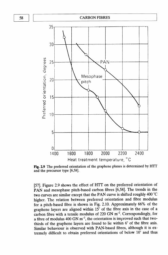
58 I LI _________________ C_A_R_B_O_N __ fl_B_R_E_S ________________ _
V> <l.l <l.l I-
01 <l.l
U -
C 0 +-' m +-' c <l.l
"-0
-0 <l.l '-I-
<l.l -<l.l I-
CL
35
30
25
20
15
10
5
o 1400
\ ~
\ ~ '" PAN ~
~ Mesophase ~
~ " "'" \~ \)
~, \--
1600 1800 2000 2200 2400 Heat treatment temperature, 0 C
Fig. 2.9 The preferred orientation of the graphene planes is determined by HTT and the precursor type [6,58].
[57]. Figure 2.9 shows the effect of HIT on the preferred orientation of PAN and mesophase pitch-based carbon fibres [6,58]. The trends in the two curves are similar except that the PAN curve is shifted roughly 400°C higher. The relation between preferred orientation and fibre modulus for a pitch-based fibre is shown in Fig. 2.10. Approximately 66% of the graphene layers are aligned within 15" of the fibre axis in the case of a carbon fibre with a tensile modulus of 220 GN m-2• Correspondingly, for a fibre of modulus 400 GN m-2, the orientation is improved such that twothirds of the graphene layers are found to lie within 6° of the fibre axis. Similar behaviour is observed with PAN-based fibres, although it is extremely difficult to obtain preferred orientations of below 10° and thus

L-________ TH __ E __ ST_R_U_CT __ U_RE __ O_F __ CA_R_B_O_N __ F_IB_RE __ S ________ ~I I 59
800 r---------------------.
Iil 600
a. ~ III ::J 400 S "'0 0 ~
200
0~--r_-~--_+--~--+_-_4--~
5 10 15 20 25 30 35
Preferred orientation (full width at half maximum), degrees
Fig. 2.10 The relationship between tensile modulus and preferred orientation for a pitch-based carbon fibre.
moduli greater than 400 GN m-2• In contrast, it is significantly easier to obtain orientation down to 5° in pitch-based fibres such that fibres with moduli in excess of 800 GN m-2 have been produced on the laboratory scale [59]. Direct lattice imaging using high-resolution transmission electron microscopy (TEM) has shown that the graphene planes stack on top of each other rather like the pages in a book. They are ribbon-like in structure having widths of the order, typically, of a few hundred nanometres. An artist's impression of the arrangement of these planes in an ex-PAN fibre is shown in Fig. 2.11 [60]. In a longitudinal fibre cross-section, as sketched in Fig. 2.12 [61], the ribbons, which are stacks of graphene layers, would be seen to undulate and separate but the majority would be roughly aligned along the fibre axis. The presence of needle-like voids (as shown in Fig. 2.11) reduces the fibre density below the value (2.26 g cm-3) one would predict for an idealized planar structure of hexagonally arrayed carbon atoms. Figure 2.12 indicates the 'crystallite' dimensions La and L e ,
representing the extent of relatively straight portions of the lattice planes along their length, and the stacking height of the graphene planes in the ribbons respectively. Increasing the HTT allows the graphene planes to grow, with concomitant increases in La and Le as the fibre tends towards a higher modulus.
2.3.2 Radial structure
A cross-section across the fibre axis, as shown in Fig. 2.10, indicates a much higher state of disorder than in a longitudinal section (Fig. 2.11).

60 I IL-_______ _ _ C_A_RB_O_N_F_I_B_R_E_S _ _____ _ _ ----'
c .Q
~ If)
o c
U :::J ...-
"en ~
Transverse section
(narrow I surta:e I ; ~ter ;or region
~~~rn~:::Poros ity
"Hairpin" defect
Fig. 2.11 Artist 's impression of the structure of a high-strength PAN-based carbon fibre [60).
A transverse section shows the planes to be twisted over much shorter distances than the width of ribbons. Additionally, there is a random orientation of planes over the diameter of the fibre. The radial structure of the graphene planes varies with processing conditions and type of fibre. Radial texturing increases with the degree of axial preferred orientation [62,63].
Figure 2.13 shows an SEM micrograph of an ultra-high modulus mesophase pitch-based carbon fibre (Amoco P75) illustrating its radial axial texture. If the extrusion of the pitch is performed without stirring, such radial structures tend to be formed. Stirring of the pitch melt during spinning has the effect of reducing the structural ordering of the resultant fibres, as characterized by such parameters as the interlayer spacing C and the crystallite size Lc [64].
A number of other cross-sectional structures can be achieved by stirring the pitch, such as random and onion-skin rather than radial (Fig. 2.14). The very stiff and brittle radial structured pitch-based carbon fibres such as P75 and P100 are often damaged such that a section fractures and becomes detached during handling. Fibres damaged in this way are referred to as having a 'Pac-man' section as a result of their resemblance to the computer game character (Fig. 2.14).
Polyacrylonitrile-based fibres may have contorted graphene planes and exhibit what are called 'onion-skin' structures. Low and intermediate modulus PAN fibres (E < 350 GN m-2) have a highly contorted transverse

L--_____ TH_E_S_T_R_U_CT_U_R_E_O_F_C_A_R_B_O_N_F_IB_R_E_S _____ I 1 61
200 A
Fig.2.12 Sketch of a longitudinal cross-section along the fibre axis of a PAN-based carbon fibre [61]. The in-plane and c-axis structural coherence lengths La and L, are indicated.
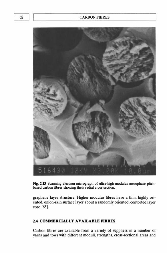
62 I LI _________________ C_A_RB __ O_N_F_I_B_R_E_S ________________ ~
Fig. 2.13 Scanning electron micrograph of ultra-high modulus mesophase pitchbased carbon fibres showing their radial cross-section.
graphene layer structure. Higher modulus fibres have a thin, highly oriented, onion-skin surface layer about a randomly oriented, contorted layer core [65].
2.4 COMMERCIALLY AVAILABLE FIBRES
Carbon fibres are available from a variety of suppliers in a number of yarns and tows with different moduli, strengths, cross-sectional areas and

~ _________ C_O_M_M_E_R_C_I_A_L_L_Y_A_V_A_I_L_A_B_LE __ F_IB_RE __ S ________ ~I I 63
Radial Onion-skin Random "Pac-man"
Flat-layer Radial-folded Line-origin "Dog-bone"
Fig. 2.14 Possible cross-sectional morphologies of high-performance carbon fibres.
shapes, twists and number of fibre ends. They may be purchased in a multitude of different forms including continuous tows, chopped and milled, woven fabrics and three-dimensional preforms (Section 2.6). The diversity and tailorability of the properties of carbon fibres are one of their advantages but, accordingly, are also a problem in that a complete evaluation is difficult and expensive to obtain. It is possible, however, to make a number of generalizations:
1. The fibres produced from PAN and mesophase pitch have significantly different combinations of properties and hence, applications. At present they cannot be considered interchangeable.
2. There are generally four classes of carbon fibre subdivided by moduli: low, intermediate, high and ultra high. Subdivision into these categories is not, unfortunately, as straightforward as, for example, metal alloys. Although the fibres made by different manufacturers may be similar they are not identical. Subtle differences in choice of precursor and processing conditions may have quite significant effects on the fibre properties and on its behaviour when combined into a composite. Constant improvements by the suppliers to their products have resulted in a degree of overlap between the categories.
3. The fibre selections that make up a particular manufacturer's grade, but have different numbers of fibres within the tows, are usually, but not always, based on the same precursor. While the fibres within each grade may be considered to possess the same properties, the fibre count or degree of twist, etc. may affect subsequent composite properties.
4. It is not possible to list all of the properties of the different suppliers'

64 I I'---________ C_A_RB_O_N_F_I_B_RE_S ________ -----'
products; Table 2.5 lists the general properties for a number of products.
5. The range of carbon fibre grades in present use is between 5 and 11 ~m in diameter. The trend is towards smaller and smaller fibre diameters in order to attain improved tensile strength and processing speeds. The compressive and transverse properties of composites employing smaller diameter fibre reinforcement do not increase in proportion with tensile properties. As a result failure in compression may result at lower than predicted loads as a result of buckling.
6. Secondary load-bearing structures generally require at least 1.5% strain to failure and primary structures 2% or better. As a result, 1M PANbased grades are generally preferred for such tasks.
7. The major advantage of mesophase pitch-based fibres is that they can be made into ultra high modulus (E > 600 GN m-2), and their use is generally limited to space structures because of their excessive cost (up to £1000 kg-l).
8. Great care must be taken when selecting a reinforcing fibre for a carbon--carbon composite to avoid a situation arising in which a component is required to operate at a temperature higher than the temperature at which it was produced, when a corresponding change in properties may result. For this reason a lot of carbon-carbon materials are based on heat-treated (post-weaving) fabrics, to ensure that no shrinkage occurs throughout the process.
2.S SURFACE TREATMENT OF CARBON FIBRES AND INTERFACIAL BONDING
Carbon fibres, especially those of HM, are extremely difficult to wet and bond with polymeric resins and virtually impossible to couple with metals [66]. In order to form a bond between fibre and matrix capable of affording an efficient stress transfer in a carbon fibre reinforced composite system, it is necessary to apply some form of surface treatment to the fibres. Such treatments serve to increase the number of active chemical groups on the fibre surface and/or roughen the fibre surface to increase the amount of mechanical 'keying' between fibre and matrix. Chemical coatings, known as 'sizes', have been extensively developed for the epoxy family of resins (the most common matrix in polymer composite systems). The size, which is applied prior to shipping, prevents fibre abrasions, improves handling and provides an epoxy-compatible interface by the inclusion of coupling agents such as titanates [67]. Other techniques include oxidation using liquid agents (nitric acid, potassium permanganate, etc.) [68], gaseous oxidation [69], gas plasma techniques [70] and a whole host of others as reviewed by Delmonte [51].
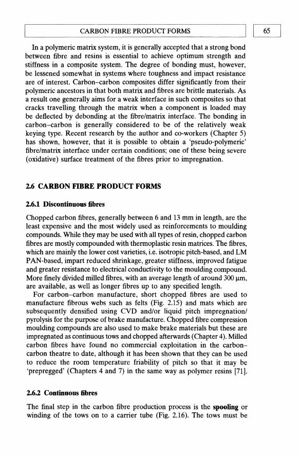
L-_____ C_A_R_B_O_N_FI_B_R_E_P_R_O_D_U_CT __ FO_RM __ S _____ ---1I I 65
In a polymeric matrix system, it is generally accepted that a strong bond between fibre and resins is essential to achieve optimum strength and stiffness in a composite system. The degree of bonding must, however, be lessened somewhat in systems where toughness and impact resistance are of interest. Carbon-carbon composites differ significantly from their polymeric ancestors in that both matrix and fibres are brittle materials. As a result one generally aims for a weak interface in such composites so that cracks travelling through the matrix when a component is loaded may be deflected by debonding at the fibre/matrix interface. The bonding in carbon-carbon is generally considered to be of the relatively weak keying type. Recent research by the author and co-workers (Chapter 5) has shown, however, that it is possible to obtain a 'pseudo-polymeric' fibre/matrix interface under certain conditions; one of these being severe (oxidative) surface treatment of the fibres prior to impregnation.
2.6 CARBON FIBRE PRODUCT FORMS
2.6.1 Discontinuous fibres
Chopped carbon fibres, generally between 6 and 13 mm in length, are the least expensive and the most widely used as reinforcements to moulding compounds. While they may be used with all types of resin, chopped carbon fibres are mostly compounded with thermoplastic resin matrices. The fibres, which are mainly the lower cost varieties, i.e. isotropic pitch-based, and LM PAN-based, impart reduced shrinkage, greater stiffness, improved fatigue and greater resistance to electrical conductivity to the moulding compound. More finely divided milled fibres, with an average length of around 300 f..Lm, are available, as well as longer fibres up to any specified length.
For carbon-carbon manufacture, short chopped fibres are used to manufacture fibrous webs such as felts (Fig. 2.15) and mats which are subsequently densified using CVD and/or liquid pitch impregnation/ pyrolysis for the purpose of brake manufacture. Chopped fibre compression moulding compounds are also used to make brake materials but these are impregnated as continuous tows and chopped afterwards (Chapter 4). Milled carbon fibres have found no commercial exploitation in the carboncarbon theatre to date, although it has been shown that they can be used to reduce the room temperature friability of pitch so that it may be 'prepregged' (Chapters 4 and 7) in the same way as polymer resins [71].
2.6.2 Continuous fibres
The final step in the carbon fibre production process is the spooling or winding of the tows on to a carrier tube (Fig. 2.16). The tows must be
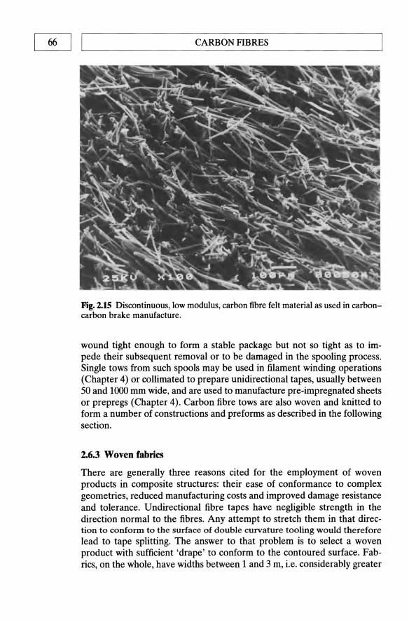
CARBON FIBRES 66 I I ~----------------------------------------------------~
Fig. 2.15 Discontinuous, low modulus, carbon fibre felt material as used in carboncarbon brake manufacture.
wound tight enough to form a stable package but not so tight as to impede their subsequent removal or to be damaged in the spooling process. Single tows from such spools may be used in filament winding operations (Chapter 4) or collimated to prepare unidirectional tapes, usually between 50 and 1000 mm wide, and are used to manufacture pre-impregnated sheets or prepregs (Chapter 4). Carbon fibre tows are also woven and knitted to form a number of constructions and preforms as described in the following section.
2.6.3 Woven fabrics
There are generally three reasons cited for the employment of woven products in composite structures: their ease of conformance to complex geometries, reduced manufacturing costs and improved damage resistance and tolerance. Undirectional fibre tapes have negligible strength in the direction normal to the fibres. Any attempt to stretch them in that direction to confonn to the surface of double curvature tooling would therefore lead to tape splitting. The answer to that problem is to select a woven product with sufficient 'drape' to conform to the contoured surface. Fabrics, on the whole, have widths between 1 and 3 m, i.e. considerably greater

~ __________ C_A_R_B_O_N __ F_IB_R_E_P_R_O_D_U_CT ___ FO __ R_M_S __________ ~I I 67
Fig. 2.16 Typical carbon fibre spools (courtesy Ciba-Geigy).
than that of tapes (50-1000 mm). It is thus possible to lay up larger areas without seams. If the fabric is close to being balanced, a single fabric ply will replace two orthogonal tape plies, thereby further reducing the amount of lay-up. This is particularly important in cases where automatic tape layup is not available or complexity of form precludes its use. Economic considerations alone often strongly dictate the use of fabrics especially where lamination must be done by hand. Improved laminate toughness is also an important consideration in the utilization of fabrics in brittle fibre/ brittle matrix composites such as carbon-carbon.
Woven broad goods, as an intermediate product, present the fibres in a convenient format for the design engineer, resin coater (prepregger) and component fabricator to use. A great number of variations in properties are possible by combining different yams and weaves, allowing the designer a wide range of laminate properties. The fabric pattern, or construction, is an x, y coordinate system. The y-axis represents the long axis of the fabric roll (typically 30-150 m) and is known as the warp direction. The warp yams are known as 'ends'. The x-axis in the width of the roll (generally 0.9-3 m) is known as the fill direction and fill yarns as 'picks'. One of the defining characteristics of any fabric construction is the number of ends per unit length times the number of picks per unit length. A weave is

68 I IL-________ C_A_RB_O_N_F_I_B_RE_S ________ --.J
FILLING .. Fig.2.17 illustration of weaving nomenclature: warp threads are called 'ends'; filling threads are called 'picks'; fabric construction is given as ends x picks per inch (or cm); weave design (style) describes the way the fibres interlace.
described as balanced if the same yarn and weight are used in both directions. All other waves are unbalanced. The extreme cases of unbalanced weaves are known as 'unidirectional' because only a very small amount of fill yam is used to keep what are effectively the undirectional loadcarrying yarns together. The basic nomenclature of the weaving process is illustrated in Fig. 2.17 using the example of a 'plain' weave in which the yarns are interlaced at 90· to each other [72]. Fabrics in which the weave does not lie on 0/90· orientation to the length direction are known as angle ply fabrics.
There are basically three styles of weave used in the composites industry. They are the plain, twill and satin weaves. The plain weave, which is by far the most commonly used (Fig. 2.18), consists of the picks and ends going over and under one another, resulting in an equal amount of warp and fill yarns on either side of the fabric. The curvature, or deformation, arising as a result of the weaving is known as crimp. The application of a tensile load in the plane of the fabric will tend to straighten out the crimp, manifesting itself as a reduction in strength and stiffness of a fabric composite when compared to unidirectional tape of the same material. An obvious way to increase the fabric stiffness is to reduce the amount of crimp by having as much of the warp and fill fibres as straight as feasible. Twill or 'basket' weave is a variation of the plain weave in which warp and fill yarns are paired, two up and two down. Satin weaves are a family of

'----______ C_A_R_B_O_N_F_IB_R_E_P_R_O_D_U_C_T_F_O_R_M_S _____ ------!I I 69
WARP THREAD (END)
n o I
L I ~ U LJf"-· -'--LJ~I -1,_ U L- LJ FILL THREAD (PICK)
2 3 4 5 6 7 8
WARP END
Fig. 2.18 Details of a plain weave.
constructions with a minimum of interlacing. In these weaves, the fill yarns periodically skip over several warp yarns. A float is the term used to describe the length of yarn between the crimped intersections. For example, consider the eight-harness satin weave illustrated in Fig. 2.19. It consists of each fill pick passing over seven warp ends and then under one end. The 'seven over/one under' pattern is repeated throughout the fabric such that no fioat is repeated in the same pick in one repeat of the weave. The numerical value preceding the 'HS' descriptor is always one greater than the number of warp ends over which the pick passes before crimping under a single end. The weaves obviously appear different depending on which side is viewed. When laying them up in laminates it is necessary to make a complete description to include whether each ply is laid warp or

L-__________ C_A_RB __ O_N_F_IB_R_E_P_R_O_D_U_cr __ F_O_RM __ S __________ ~1 I 71
4-H satin (16 binders)
7-H satin (10 binders)
S-H satin (13 binders)
8-H satin (8 binders)
6-H satin ( 11 binders)
Fig. 2.20 Illustration of fabric drapability using fibre styles of satin weave [72].
fibre from the outside of the warp fibres and draw it across them, after which it is cut off. The rapier then grasps another fill yarn from a spool on the opposite side of the loom and draws it back across the warp fibres. The edges of a fabric must be reinforced to allow handling in subsequent processing. The selvage is the name given to the strong woven edges of a fabric (Fig. 2.21); selvages must be removed prior to lay-up.
2.6.4 Multi-directionally reinforced fabrics and preforms
The majority of applications of composite materials in aerospace and racing cars endure relatively simple mechanical loading regimes allowing the use of two-dimensionally oriented tape or fabric reinforcement. The emergence of carbon-carbon composites over the last two and a half decades has introduced a number of complicated design problems as a result of their strongly anisotropic properties. Mechanical properties are generally satisfactory in the two dimensions containing the reinforcement fabric, but are matrix dominated in the third direction, being typically an order of magnitude less than in the reinforced directions. This problem is critical in applications involving high thermomechanical loading such as re-entry components, and especially so in artefacts such a rocket motors which are required to endure an essentially isotropic stress field (Chapter 9). The result of excessive loading in the unreinforced plane is a

CARBON FIBRES 72 I I ~--------------------------------------------------~
~I·~--------Ground----------~·I (Usefu l fabr ic)
Selvage
Fig. 2.21 Full-width plain weave fabric showing selvage.
delamination of the constituent plies and failure of the part under loads lower than designed for. The obvious solution to such problems, then, is to add fibre reinforcements in the third dimension, creating an (x , y, z) coordinate system of reinforcement.
The major advantage of multi-directional carbon- carbon composites is the freedom to orientate selected fibre types and amounts to accommodate the design loads of the final structural component. The disadvantages of multi-directional fabrication technology are the cost of producing the fibre preform, the size limitation on components as dictated by available equipment size and the difficulty of matrix impregnation between the threedimensional fibre arrays [76].
The simplest type of multi-directional preform is based on a threedirectional orthogonal construction and is normally used to weave rectangular, block-type preforms (Fig. 2.22). This type of preform consists of multiple yarn bundles located on Cartesian coordinates. Each of the bundles is kept straight so that the maximum structural capability of the fibre is maintained. The preforms are described by yarn type, number of yarns per site, spacing between adjacent sites, volume fraction of yarn in each direction and preform density. A number of modifications of the basic three-directional orthogonal construction are available in order to achieve more isotropic preforms. This is accomplished, as one would imagine, by introducing yarns in additional directions. Based on geometric principles, a variety of fibre orientations ranging from orthogonal, 3-directional to 11-directional reinforcements may presently be produced.
The various reinforcement patterns are described by the n-D nomenclature, where n represents the number of directions and D stands for

x
L-__________ C_A_R_B_O_N __ FI_B_R_E_P_R_O_D_U_C_T_F_O_R_M __ S __________ ~I I 73
z
y
3-D BLOCK (ORTHOGONAL) WEAVE
Fig. 2.22 Three-dimensional (3-D) orthogonal preform construction [77] (courtesy Hercules Inc.).
direction [77]. Thus our orthogonal reinforcement structure would be described as 3-0 (not to be confused with 3-d which means 3-dimensional!). As an example, a 5-0 construction can be achieved by adding two reinforcement directions that are ±45" with respect to the yarns within the x-y plane of the preform. Similarly, the introduction of additional diagonal yarns across the corners of the x-z plane would result in a 7-0 reinforcement and so on. Clearly the cost of assembling preforms of this type will increase almost exponentially with complexity, such that 3-D are by far the most commonly employed.
Polar weave preforms are used to form cylinders and other shapes of revolution. They are 3-0 constructions with yarns oriented on polar coordinates in the radial, axial and circumferential directions (Fig. 2.23). Preforms of this geometry normally contain 50 vol. % of fibres that can be introduced equally in the three directions. Should a specific application require unbalanced properties, a degree of variation in relative yarn distribution may be accomplished. For example, if a high hoop tensile strength is necessary, additional fibres may be added in the circumferential direction at the expense of radial and longitudinal properties.
Although originally developed as thick-walled cylinders, polar weave preforms may now be fabricated in a number of 'body of revolution' shapes such as cylinders, cylinders/cones, and convergent/divergent sections. A two-step process may be used to form non-axisymmetric shapes such as leading edges (Fig. 2.24) and conical/rectangular transitions. The first stage involves the weaving of a preform of an appropriate geometry. The preform is then placed in a metal die, deformed into the required shape and impregnated with a suitable resin to ensure geometric stability during the
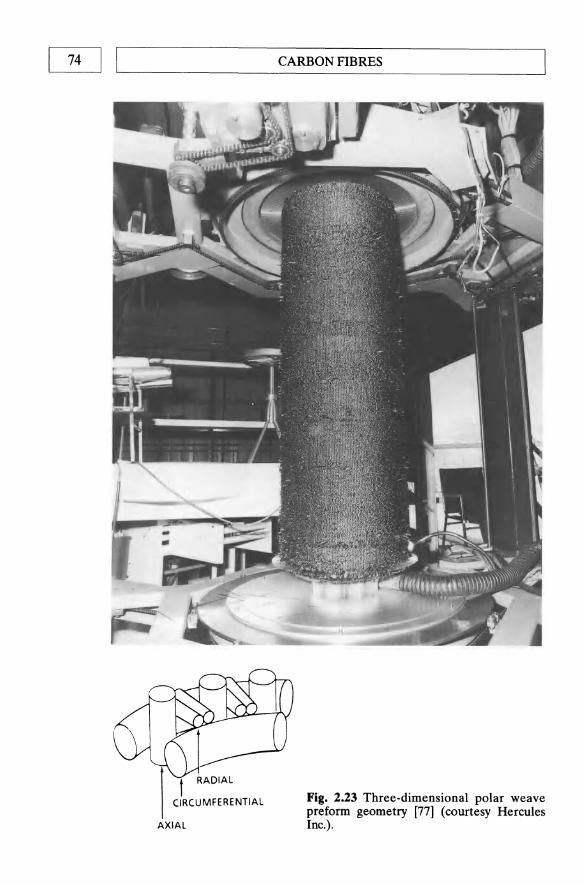
74 I I ~----------------------------------~
CARBON FIBRES
AXIAL
Fig. 2.23 Three-dimensional polar weave preform geometry [77] (courtesy Hercules Inc.).

L-__________ C_A_R_B_O_N __ FI_B_R_E_P_R_O_D_U_CT __ F_O_R_M __ S __________ ~I I 75
Woven cylinder
Cut cylinder, reshape, impregnate, cure and then ---process
Final machining
Fig. 2.24 Deformation of a 3-D cylindrical preform to produce a leading edge (courtesy Hercules Inc.).
remainder of the densification process. Depending on the shape being formed, it mayor may not be necessary to slit the preform. Formation of a leading edge as shown in Fig. 2.24. would require slitting, whereas a simple deformation from conical to conic/rectangular would not. At present, polar weave preforms may be produced up to 2.1 m in diameter and 1.3 m in length. Wall thicknesses vary from 6.4 to 200 mm and there is a minimum inside diameter constraint of ",,75 mm as a result of the space requirements of the weaving mechanism.
Angle (or warp) interlocks are multi-layered fabrics in which the warp yarns travel from one surface of the fabric to the other. Up to eight layers of fabric may be held together, creating a thick 2-D fabric as shown in Fig. 2.25(b). Should higher in-plane strength be required, additional 'stuffer' yarns may be added to create a quasi-3-D fabric (Fig. 2.25(a)). Despite angle interlock being economical to produce on commercially available weaving equipment, its use is limited because it is unavailable in closed geometries. The production of cones and cylinders using such fabrics would be inherently weak because of the requirement of joints and their attendant plane of weakness.
Both stitched fabric and needled felt may be considered 3-D preforms although, despite having reinforcement in all three dimensions, the amount of fibre in the inter-ply direction is more often than not negligible. The inter-ply properties of both these fabrics are, thus, seldom significantly better than the matrix-dominated properties of 2-D composites.
The majority of multi-directional preforms used in carbon-carbon manufacture are represented by the orthogonal or polar constructions or by some modification of these constructions. The techniques used to manufacture the preforms include weaving dry yarns [78], piercing fabrics

76 I LI _________________ C_A_RB __ O_N_B __ B_R_E_S ________________ _
Ends of filling yarns (weft) Path of t pical warp yarn
Warp -I--+--I--\---I--\--+-\--I--\--I-~-I-~~~---1 stu ffer
(a)
Ends of filling yarns (weft)
(b)
yarns
Path of typical warp yarn
Fig.2.25 Geometry of angle-interlock fabric (a) with and (b) without added stuffer yams.
[79], assembling resin-rigidized yarns [80] and modified filament winding technology [81]. Infiltration or impregnation of the carbon matrix becomes increasingly difficult with increasing thickness of preform and complexity of reinforcement. Chemical vapour deposition (Chapter 3) can be used only on relatively thin sections (up to a few centimetres). Vacuum impregnation with polymeric resins followed by pyrolysis (Chapter 4) is a possible method, but by far the most efficient is the hot isostatic pressure impregnation carbonization (IDPIC) process using petroleum or coal-tar pitch as a matrix precursor (Chapter 5).

CARBON FIBRE PRODUCT FORMS I I 77 L-__________________________________________________ ~
(a) (b)
Fig. 2.26 Fabric techniques: (a) braided; (b) woven.
2.6.5 Braiding
Braiding is a textile process known for its simplicity, in which two or more systems of yarns are intertwined in the bias direction to form an integrated structure. Braided structures differ from woven fabrics in the method of yarn introduction into the fabric and in the manner by which the yarns are interlaced (Fig. 2.26). Braiding is similar in many ways to filament winding (Chapter 4). Dry fibre tows or prepreg tapes may be braided over a rotating and removable mandrel in a controlled manner to form a variety of shapes, fibre orientations and fibre volume fractions. Braiding cannot achieve as high a fibre volume fraction as filament winding, but braids can assume more complex shapes. The interlaced nature of braids provides a higher level of structural integrity, essential for ease of handling, joining and damage resistance. The low interlaminar properties of composites can be lessened by use of a three-dimensional braiding process [82]. The application of braided materials in composite engineering materials was initiated in the late 1970s [83]. The current trend in braiding technology is to expand to large-diameter braiding, develop more sophisticated techniques for braiding over complex-shaped mandrels, multi-directional braiding, production of near-net-shape preforms (Fig. 2.27) and the extensive use of computer-aided design and manufacturing (CAD/CAM).
A typical braiding machine (Fig. 2.28) consists of a track plate, spool carrier, former and a take-up device. In some cases a reversing ring is used
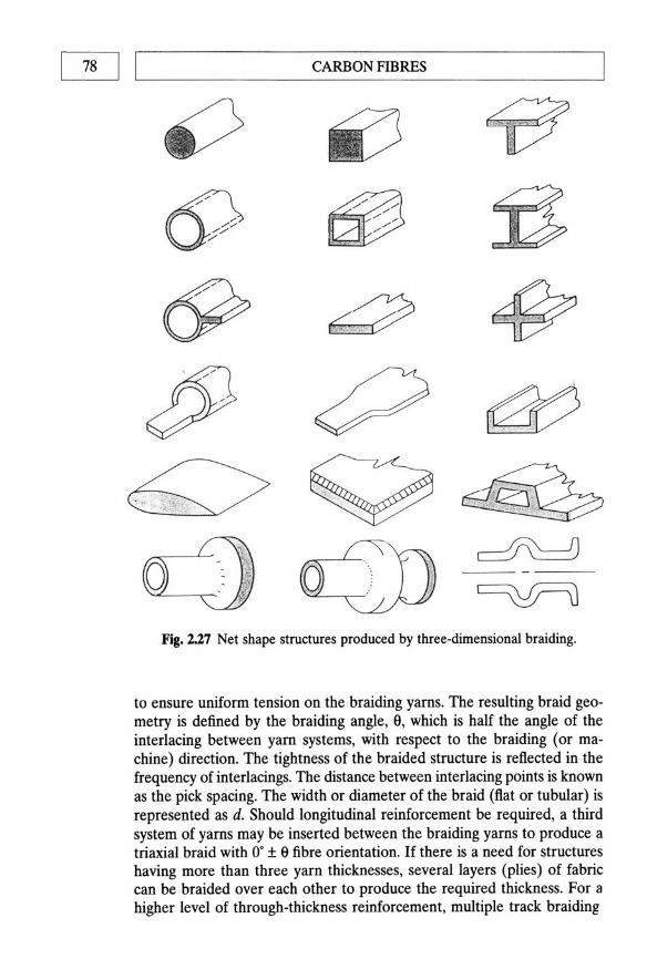
~ LI ______________ ~CA_RB __ O~N~F~IB~R~~=_ ____________ __
i~
a "
Fig. 1.27 Net shape structures produced by three-dimensional braiding.
to ensure uniform tension on the braiding yams. The resulting braid geometry is defined by the braiding angle, 9, which i s half the angle of the interlacing between yam systems, with respect to the braiding (or machine) direction. The tightness of the braided structure is reflected in the frequency of interlacings. The distance between interlacing points is known as the pick spacing. The width or diameter of the braid (fiat or tubular) is represented as d. Should longitudinal reinforcement be required, a third system of yarns may be inserted between the braiding yarns to produce a triaxial braid with O· ± 9 fibre orientation. If there is a need for structures having more than three yarn thicknesses, several layers (plies) of fabric can be braided over each other t o produce the required thickness. For a higher level of through-thickness reinforcement, multiple track braiding
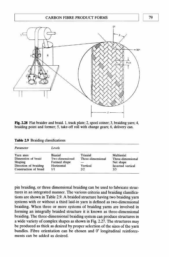
L-__________ C_A_R_B_O_N_F_IB_R_E __ P_R_O_D_U_CT __ F_O_R_M_S __________ ~I I 79
o·
Fig. 2.28 Flat braider and braid. 1, track plate; 2, spool coiner; 3, braiding yam; 4, braiding point and former; 5, take-off roll with change gears; 6, delivery can.
Table 2.9 Braiding classifications
Parameter
Yarn axes Dimension of braid Shaping Direction of braiding Construction of braid
Levels
Biaxial Triaxial Two-dimensional Three-dimensional Formed shape Horizontal Vertical 111 2/2
Multiaxial Three-dimensional Net shape Inverted vertical 3/3
pin braiding, or three dimensional braiding can be used to fabricate structures in an integrated manner. The various criteria and braiding classifications are shown in Table 2.9. A braided structure having two braiding yarn systems with or without a third laid-in yarn is defined as two-dimensional braiding. When three or more systems of braiding yarns are involved in forming an integrally braided structure it is known as three-dimensional braiding. The three-dimensional braiding system can produce structures in a wide variety of complex shapes as shown in Fig. 2.27. The structures may be produced as thick as desired by proper selection of the sizes of the yarn bundles. Fibre orientation can be chosen and O· longitudinal reinforcements can be added as desired.

00 I LI _________________ CA __ RB_O_N __ fl_B_R_E_S ________________ ~ 2.7 FOOTNOTE
Carbon fibres may be made in a variety of grades and forms each with their own characteristics. The ability to vary the properties considerably by varying processing conditions and choice of precursor allows considerable 'tailoring' of the reinforcement phase within a carbon-carbon composite. While this tailorability of reinforcement properties is clearly of advantage in forming a composite, it also creates a severe problem when trying to categorize, evaluate and standardize properties. The following three chapters will show how similar effects are available when introducing the matrix phase. It is thus possible to see how carbon-carbon is not a single material but rather a family or class of materials whose properties can be varied depending on how and from what they are made.
Polyacrylonitrile and pitch represent the major categories of carbon fibres. Both have a unique set of advantages and disadvantages, but PAN-based fibres are the dominant fibres today and are expected to remain so for the foreseeable future. They posses an excellent balance of mechanical properties, good handle ability and an extensive data base. New products are continually being introduced with the emphasis on higher strength and higher modulus. As the world-wide demand for carbon fibre grows there is an increasing emphasis on improved manufacturing technology in order to meet competitive carbon-fibre pricing and lower the capital requirements for new capacity.
Pitch-based carbon fibres develop a high modulus far more easily than those derived from PAN. They are an excellent reinforcing fibre if stiffness, coefficient of thermal expansion or conductivity are important. The key process development area for both economics and properties is improved mesophase technology in spinning and the handling of exceedingly brittle as-spun fibres. Continued success in pitch technology (quality, price, performance, etc.) will lead to increased consumption into applications with low (industrial) and ultra-high (space) modulus requirements. At present there is only one commercial supplier in the West (Amoco in the USA) and a number in Japan. One would therefore expect to see a number of others over the next 3-5 years, perhaps in Europe.
REFERENCES
1. Griffith, A. A. (1920) Phil. Trans. Roy. Soc. London, 221A. 2. Savage, G. M. (1989) Metals and Materials, 5, 285. 3. Savage, G. M. (1988) Metals and Materials, 4, 544. 4. Duthie, A. C. (1987) Proc. PRJ. Conf. Polym. in Def., Bristol, 18-20 March. 5. Stein, B. A. and Johnson, N. J. (1985) Proc. ASTM Symp. on Toughness of
Composites, Houston, Texas, March 1985.

~ _________________ R_E_FE __ R_E_N_C_E_S ________________ ~1 I 81
6. D'Abate, G. D. and Diefendorf, R 1. (1985) Proc. 17th Biennal Con! on Carbon, Am. Carbon Soc., p. 390.
7. Berman, R (1979) in The Properties of Diamond (ed. J. E. Field), Academic Press, New York.
8. Carbon, 20 (5), 445 (1982). 9. Edison, T. (1880) US Patent 223,898.
10. Milanski, 1. V. and Katz, H. (eds) (1987) Handbook of Reinforcements for Plastics, Van Nostrand Reinhold Amsterdam.
11. Fitzer, E. (1989) Carbon, 27 (5), 621. 12. Shindo, A (1961) Osaka Kogyo Gijitsu Shikuko, U, 110,119. 13. Bacon, R, Pallozza, A A and Slosarik, S. E. (1966) Proc. Soc. Plastics Ind.
21st Tech. and Mang. Con!, Sect 8E. 14. Shindo, A (1961) Rept Covt. Ind. Res. Inst., Osaka, 317. 15. Shindo, A (1964) Carbon, 1, 39l. 16. Watt, W., Philips, L. N. and Johnson, W. (1966) The Engineer, 221, 815. 17. Standage, A E. and Prescott, R (1966) Nature (London), 211, 169. 18. Hughes, T. V. and Chambers, C. R (1889) UK Patent 405,480. 19. Oberlin, A, Endo, M. and Koyama, T. (1976) 1. Cryst. Growth, 32, 335. 20. Johnston, W., Phillips, L. N. and Watt, W. (1964) UK Patent 1,110,791. 21. Johnston, W., Phillips, L. N. and Watt, W. (1968) US Patent 3,412,062. 22. Singer, L. S. (1977) US Patent 4,005,183. 23. Bacon, Rand Schalamon, W. A (1967) Proc. 8th Biennial Can! on Carbon,
Am. Carbon Cttee. 24. Hawthorne, H. (1971) Proc. 1st Int. Con! on Carbon Fibres, Plastics Ind.,
p. 81. 25. Soltes, W. (1961) US Patent 3,001,981. 26. Abbott, W. (1962) US Patent 3,053,775. 27. Otani, S. (1965) Carbon, 3, 213. 28. Singer, L. S. (1972) Netherlands Patent 239490. 29. Gill, R M. (1972) Carbon Fibres in Composite Materials, published for the
Plastics Institute, London, by ILIFFE Books, London. 30. Watt, W. and Perov, B. V. (eds) (1985) Strong Fibres, Amsterdam. 31. Dresselhaus, M. S., Dresselhaus, G., Sugihara, K., Spain, I. L. and Goldberg,
H. A (1988) Graphite Fibres and Filaments, Springer-Verlag, Heidelberg. 32. Henrici-Olive, G. and Olive, S. (1983) in Industrial Developments (Advances
in Polymer Science, 51), Springer-Verlag, Heidelberg, p. 1. 33. Hay, J. N. (1968) 1. Polym. Sci. Al (6),2127. 34. Watt, W. and Green, 1. (1971) Proc. Int. Carbon Fibre Conf., Plastics Inst.,
London, Paper 4. 35. Clarks, A J. and Bailey, J. F. (1973) Nature, 243, 146. 36. Fitzer, E. and Muller, D. J. (1975) Carbon, 13, 163. 37. Toray Inc. (1970) German Patent 1,958,361. 38. Raskovic, V. and Marinkovic, S. (1978) Carbon, 16, 351. 39. Watt, W., Johnson, D. 1. and Parker, E. (1974) Proc. 2nd Int. Carbon Fibre
Cont, Plastics Inst., London, Paper 1. 40. Johnson, D. J. (1971) Inst. Carbon Fibre Cant, Plastics Inst., London, Paper
8.

82 I ~I _________________ C_A_RB __ O_N __ B_B_RE __ S ________________ ~ 41. Rose, P. G. (1977) Kohlenstoffund Aramidfaser Verstiirkte Kunststoffe, VDI
Verlag GmbH, p. 9. 42. Johnson, W. (1971) Proc. Third Con! Ind. Carbons and Graphites, Soc. Chem.
Ind., London, p. 447. 43. Reynolds, W. N. (1971) Proc. Third Con! Ind. Carbons and Graphites, Soc.
Chem. Ind., London, p. 427. 44. Reynolds, W. N. and Sharp, J. V. (1974) Carbon, 12, 103. 45. Moreton, R. and Watt, W. (1974) Nature, 247, 360. 46. Johnson, J. W. (1969) J. App. Polym. Symp., 9, 229. 47. Stewart, M. and Feughelman, M. (1973) J. Mat. Sci., 8, 1119. 48. Watt, W. and Johnson, W. (1969) CASI Trans., 2, 81. 49. Johnson, J. W. and Thome, D. J. (1969) Carbon, 7, 659. 50. Moreton, R. (1969) Fibre Sci. Tech., 1, 273. 51. Delmonte, J. (1981) Technology of Carbon and Graphite Fibre Composites, Van
Nostrand Reinhold, New York. 52. Ohama, Y. (1989) Carbon, 27 (5), 729. 53. Volk, H. F. (1977) Proc. Symp. on Carbon Fibre Reinforced Plastics, Bamberg,
FRG, 11 May 1977. 54. Riggs, J. P. (1985) in Encyclopedia of Polymer Science and Engineering, 2, Wiley,
New York, p. 640. 55. Hughes, J. D. H. (1987) J. Phys. D: Appl. Phys., 20, 276. 56. Edie, D. D. and Dunham, M. G. (1989) Carbon, 27 (5), 647. 57. Ruland, W. (1968) Polym Pre prints, Polymer Chemistry Div. Am Chem. Soc.,
9 (2), 1368. 58. Le Maistre, C. W. and Diefendorf, R. J. (1973) SAMPE Quart., 4,1. 59. Diefendorf, R. J. (1988) in Engineered Materials Handbook, 1, Composites, ASM
Int. p. 49, Amsterdam. 60. Guigon, M., Overlin, A and Desarmot, G. (1984) Fibre Sci. Tech., 20,177. 61. Fordeaux, A, Perret, R. and Ruland, W. (1971) Proc. Int. Con! on Carbon
Fibres, their Composites and Applications, London, Plastics and Polymer Conference Supplement no. 5, Plastics inst., London, p. 57.
62. Tokarsky, E. W. and Diefendorf, R. J. (1975) Polym. Eng. Sci., 15 (3), 150. 63. Diefendorf, R. J. and Tokarsky, E. W. (1975) Report AFMI-TR-72-133, parts
I-IV, US Air Force Mats. Lab. 64. Bright, A A. and Singer, L. S. (1979) Carbon, 17, 59. 65. Butler, B. L. and Diefendorf, R. J. (1970) Proc.l0th Carbon Composite Tech,
Symp. Am. Soc. Mech. Eng., p. 109. 66. Donnet, J. B. and Ehrberger, P. (1977) Carbon, 15, 143. 67. Monte, S. J., Sugarman, G. and Seeman, D. J. (1977) Proc. 32nd Ann. Tech.
Con!, SPI, RP/C Inst. Washington, DC, Feb. 1977. 68. Barr, J. (1974) US Patent 3,791,840. 69. Nyo, H., Heckler, D. L. and Hoemshcemeyer, P. L. (1979) SAMPE, 24th Nat.
Symp., 14, 51, May 1979. 70. De Lolhis, N. J. (1979) SAMPE J., 15 (3), 10. 71. Savage, G. M. unpublished results. 72. Bailie, J. A. (1989) Woven fabric aerospace structures, in Structure and Design
(eds C. T. Herakovich and Y. M. Tamopoloski), Metals Park, Ohio, NorthHolland, pp. 353-91.

~ __________________ RE __ FE __ RE __ N_C_E_S __________________ ~I I 83
73. Ishkiawa, T. and Chou, T. W. (1982) 1. Compo Mat., 6, 2. 74. Ishikawa, T. and Chou, T. W. (1983) AIAA J, 21 (12), 1714. 75. Levin, J. (1975) SAMPE Quart., 20. 76. McAllister, L. E. and Taverna, A. R. (1971) Proc. 73rd Ann. Mtg Am. Ceram,
Soc., Chicago. 77. Fabrication of Composites (Handbook of Composites, 4) (eds A. Kelly and
S. T. Mileiko (1986), Amsterdam. 78. Barton, R. S. (1968) SPE J., 4 (May), 31. 79. McAllister, L. E. and Taverna, A. R. (1972) Proc. 17th Nat. SAMPE Symp.,
Paper IIIA-3, AZ, USA. 80. Lamicq, P. (1977) Proc. AIAAlSAE 13th Prop. Conf, Paper 77-882, Orlando. 81. Mullen, C. K. and Roy, P. J. (1972) Proc. 17th Nat. SAMPE Symp., Paper I1IA-
2, AZ, USA. 82. Sanders, L. R. (1977) SAMPE Quart., 38. 83. Post, R. J. (1977) Proc. 22nd Nat. SAMPE SYmp., p. 486.

Gas Phase ImpregnationiDensification
of Carbon-carbon and other High-temperature
Composite Materials
3.1 THE CVD PROCESS
Chemical vapour deposition (CVD) is a process in which a solid product nucleates and grows on a substrate, by decomposition or reaction of gaseous species, and involves the heating of a fibre preform in a gaseous environment so that the matrix is deposited from the gas phase. The technology developed to date allows fine control over the composition and morphology of the solid deposit. Various processes have been used for the production of thin film semiconductor devices for the communications industry and the production of hard, abrasion-resistant coatings on cutting tools and coatings on radioactive pellets. The CVD techniques have also been widely used for the preparation of oxidation- and wear-resistant coatings to carbon-carbon composites. Well-processed CVD-derived composites generally possess excellent mechanical properties as a consequence of the slow, steady build-up of matrix material around the fibre network. The CVD method has proven especially useful for the production of ceramic matrix composites, where melt-processing techniques are inapplicable and conventional powder-processing methods - such as those used for the production of monolithic ceramics - result in serious fibre degradation. The major drawback of CVD is the very slow rate of deposition, leading to large material/energy inputs and a high final cost.
3

86 I LI _______ G_A_S_P_H_A_S_E_I_M_P_R_E_G_N_A_T_I_O_N_ID_E_N_S_IF_IC_A_T_I_O_N ______ __
The patent literature on inorganic composite materials (including carbon and ceramic matricies) is the subject of a recent monograph [1]. Several workers active in the field refer to CVD densification of composites as chemical vapour infiltration (CVI). The purpose of this nomenclature is to distinguish the deposition of material in fibre preform from the simple layer deposition techniques used in the semiconductor and coatings industries. It will become apparent throughout the text that the deposition of material within the pore system of a fibre preform imposes severe kinetic limitations on industrially operated CVD processes.
3.2 PHYSICO-CHEMICAL PRINCIPLES OF THE CVD PROCESS
The CVD process is, in principle, a very simple one. A gas (or mixture of gases) comes into contact with a hot surface, and reacts to deposit the thermodynamically stable phase. In practice, however, the mechanistic and kinetic features of CVD may be extremely complex.
3.2.1 Thermodynamics
Any simple hydrocarbon gas will become thermodynamically unstable with respect to carbon at elevated temperatures. Carbon deposition usualy results in a volume increase for the system such that the Tll.S entropy term in the free energy equation overcomes any endothermic enthalpy term. Simple free energy calculations can be performed to predict the onset of carbon depositions for the various reactions, for example:
(3.1)
For simple C2 species, the order of stability is C2H6 > C2H4 > C2H 2•
Methane is one of the most stable hydrocarbons. Temperatures in excess of 550°C are required before carbon deposition is thermodynamically favourable. Even at this temperature, the rate is very slow, necessitating higher temperatures for measurable deposition rates. The widespread availability of methane and its excellent diffusion properties have, nevertheless, made it the most common raw material for carbon matrices in CVD-fabricated composites. The processes are generally operated at low pressures, or by adding inert diluent gases such as H2, He, N2 or Ar to the gas stream in order to improve diffusion conditions by increasing the mean free path of the gas molecules.
The CVD of ceramic matrices is less straightforward than carbon. Oxide ceramics can be deposited from a single alkoxide precursor (such as SiOz from Si(OEt)4, or Ti02 from Ti(OiPr)4 for example), but generally two reacting precursor materials are needed. Some representative reaction mixtures are shown:
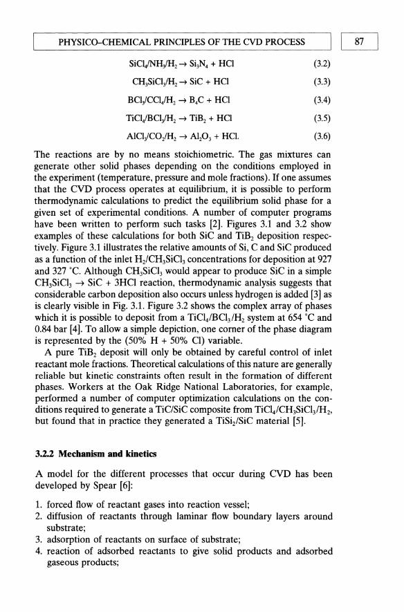
t-.._P_HY_S_IC_O-_C_HE_M_I_CAL __ P_R_IN_C_IP_L_E_S_O_F_T_HE_C_VD __ PR_o_c_E_s_s_-----'1 I 87
SiCl/NHiH2 ~ Si3N4 + HCI
CH3SiCliH2 ~ SiC + HCI
BCliCCl/H2 ~ B4C + HCI
TiCliBCliH2 ~ TiB2 + HCI
AlCliCO/H2 ~ AIP3 + HCI.
(3.2)
(3.3)
(3.4)
(3.5)
(3.6)
The reactions are by no means stoichiometric. The gas mixtures can generate other solid phases depending on the conditions employed in the experiment (temperature, pressure and mole fractions). If one assumes that the CVD process operates at equilibrium, it is possible to perform thermodynamic calculations to predict the equilibrium solid phase for a given set of experimental conditions. A number of computer programs have been written to perform such tasks [2]. Figures 3.1 and 3.2 show examples of these calculations for both SiC and TiB2 deposition respectively. Figure 3.1 illustrates the relative amounts of Si, C and SiC produced as a function of the inlet H2/CH3SiCl3 concentrations for deposition at 927 and 327°C. Although CH3SiCl3 would appear to produce SiC in a simple CH3SiCl3 ~ SiC + 3HCl reaction, thermodynamic analysis suggests that considerable carbon deposition also occurs unless hydrogen is added [3] as is clearly visible in Fig. 3.1. Figure 3.2 shows the complex array of phases which it is possible to deposit from a TiCl4/BCl3 1H2 system at 654 "C and 0.84 bar [4]. To allow a simple depiction, one comer of the phase diagram is represented by the (50% H + 50% Cl) variable.
A pure TiB2 deposit will only be obtained by careful control of inlet reactant mole fractions. Theoretical calculations of this nature are generally reliable but kinetic constraints often result in the formation of different phases. Workers at the Oak Ridge National Laboratories, for example, performed a number of computer optimization calculations on the conditions required to generate a TiC/SiC composite from TiCI4/CH3SiCI3/H2, but found that in practice they generated a TiSiz/SiC material [5].
3.2.2 Mechanism and kinetics
A model for the different processes that occur during CVD has been developed by Spear [6]:
1. forced flow of reactant gases into reaction vessel; 2. diffusion of reactants through laminar flow boundary layers around
substrate; 3. adsorption of reactants on surface of substrate; 4. reaction of adsorbed reactants to give solid products and adsorbed
gaseous products;
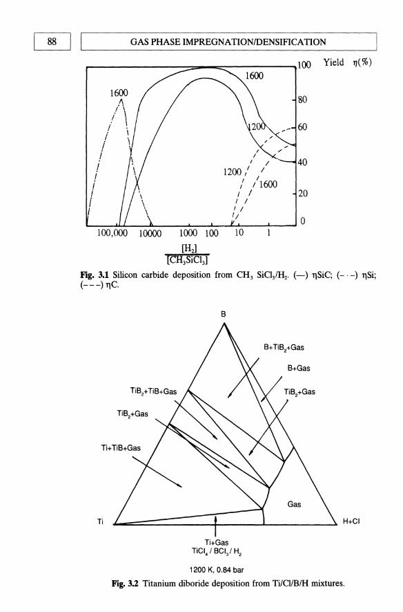
88 1 ,-I ____ G_A_S_P_H_A_S_E_IM_PRE_G_N_A_TI_O_N_ID_E_N_S_IFI_C_A_TI_O_N ___ ---'
r----------::::==-_:::::::-----~lOO Yield 1/(%)
1600
./\ I . . \
I . i \ i I i i I i J
I I
1200,' / I
" I 1600 , I I / I /
80
20
1/ ~ __ ~_~~_~_~_~-~-~O
10000 1000 100 10
[H:J [CH3SiCl3]
Fig. 3.1 Silicon carbide deposition from CH3 SiC131H2• (-) TlSiC; (_. -) TlSi; (---) TIC.
Ti
B
L-==========:J~===L----~~ H+CI
Ti+Gas TiCI4 ' BCV H2
1200 K, 0.84 bar
Fig. 3.2 Titanium diboride deposition from TilClIBlH mixtures.

L-_P_H_Y_S_IC_O-C __ HE_M_IC_A_L_PR_IN_C_IP_L_E_S_O_F_THE __ C_VD_P_R_O_C_E_S_s_----'1 I 89
5. desorption of adsorbed gaseous products; 6. diffusion of gaseous products through a boundary layer region; 7. forced flow of gaseous products through reaction vessel exit.
Any attempt to uncouple fully the overall kinetics of the CVD process in terms of these seven stages would obviously be a Herculean task. In practice the CVD process tends to be controlled by the surface reaction kinetics at low temperatures and pressures, whereas at high temperatures and pressures diffusion control dominates.
The deposition of carbon is particularly complex. A range of chemical processes can occur, dependent on the experimental conditions. The CVD process described above is essentially heterogeneous - the entire reaction occurs at the surface. In the case of carbon deposition from methane, this would correspond to a series of dehydrogenation/polymerization reactions taking place on the surface to produce graphitic materials. At high temperatures and pressures, however, pre-reaction occurs in the gas phase, generating fine, globular soot particles which agglomerate on the surface to form a low-density, mechanically weak carbon. A thorough discussion of the mechanism of carbon deposition and the morphologies of the deposits has been written by Bokros [7]. Analysis of the gaseous products from methane pyrolysis has shown that a range of aromatics are formed, indicating the complex dehydrogenation and polymerization reactions that occur [8].
Workers at the Sandia National Laboratories have made a considerable attempt to understand the chemical processes involved in the CVD of a carbon matrix around a carbon preform [9]. They suggest that methane decomposes via acetylenic or aromatic (C6) species. The relative importance of these two routes depends on the experimental conditions. Below 1250 ·C, benzene was found to be the predominant species, decomposing to give a smooth laminar carbon, characterized by a high density. Above 1250 "C, acetylene appears to predominate, with a tendency to produce an isotropic carbon. Around 1250 ·C, where a mixture of acetylenic and aromatic species occurs, an intermediate rough laminar carbon results. The relation between CVD conditions and the carbon microstructure and the resulting physical properties will be explored at a later stage (Section 3.4.2).
To date, no analysis has been made of the chemical processes involved in the CVD of ceramic materials. One important point is that sometimes low-temperature pre-reaction occurs in the gas phase, giving a deposit with poor mechanical properties. This is particularly important in the CVD fabrication of Si3N4 using SiC141NH3. Reactions occur forming a range of smokes/'soots' unless the two reactants are kept in discrete inlet systems to ensure that a reaction may only occur on the substrate. No detailed process conditions/deposit microstructure correlations have been performed for CVD-fabricated composite matrices, although Nuhara and co-workers have performed careful studies on grain size/morphology of solid plates

90 1 ,--I ____ G_A_S _PHA __ SE_IM_P_RE_G_N_A_T_I_O_N_ID_E_N_S_IF_I_CA_TI_O_N ___ ------'
-12
-13
-14
~ Ol 0
...J
-15 C2H4
-16
-17
7 8 9 10 11 12 13
104 (Kelvin)-1
K=Rate constant of CVD carbon laydown 9 cm-2 S-1 Pa-1
Fig. 3.3 Dependence of carbon deposition rates on temperature/type of hydrocarbon precursor during the CVD process.
(up to 5 mm thick) of CVD-fabricated SiC, Si3N4 and B4C, as a function of experimental conditions [10].
The kinetics of carbon deposition have been studied on a wide range of substrates by Tesner and co-workers in the former Soviet Union [11]. They concluded that rates of deposition were a complex function of reactor temperature, pressure, gas phase composition/flow rate and substrate geometry and type. Of particular interest is the dependence of deposition rate on the type of hydrocarbon precursor. Figure 3.3 shows the rate constant/temperature graph for a range of hydrocarbons displaying Arrheniustype kinetics over the temperature regions studied.
While empirical studies on the influence of experimental conditions on CVD kinetics are very valuable, it is important to realize how complex the behaviour can be. Van der Brekel and Lersmacher at the Philips Laboratories in Eindhoven have demonstrated the difference in behaviour of 'hot wall' and 'cold wall' reactor systems for carbon deposition at a given

t--_P_HY_S_IC_O_-_C_HE_M_I_CA_L_P_R_IN_C_IP_L_E_S_O_F_T_H_E_C_VD __ PR_O_C_E_S_S_--,I I 91
temperature [12]. 'Hot wall' systems rely on radiative heating from an external furnace, such that the reactor wall and reactant gases are heated up as well as the substrate. 'Cold wall' systems, on the other hand, rely on internal heating of the substrate, generally via inductive or resistive heating.
Observations on carbon deposits formed in both reactors at the same set of conditions showed that, at certain temperatures, sooty isotropic deposits are formed in the 'hot wall' system as a result of homogeneous gas phase reaction. In contrast, laminar deposits were found in the 'cold wall' reactor since the 'cold wall' configuration avoids excessive gas pre-heating.
3.2.3 eVD in a pore system
The preceding discussion of the CVD process was confined to deposition on a flat surface. Fabrication of composite materials requires deposition of the desired matrix inside and around a fibre preform - whether it be a woven continuous fibre structure, or a mat of short fibres or whiskers. The fibre preform will have a well-defined initial pore structure, dependent on fibre form, content and arrangement. It is essential that matrix material be deposited throughout the pore structure, if a strong dense composite is to result. This applies severe constraints to the CVD process. The reactants must diffuse through the boundary layer of laminar flow around the preform, diffuse into the pores and then adsorb and react. The products must be desorbed, and diffuse back out along the same route (pore and boundary layer). If the surface chemical reaction needed to produce a solid deposit occurs rapidly with respect to the diffusion processes, deposition will occur near the mouth of the pore rather than along it, rapidly sealing off the pores. Closed porosity is created which serves to concentrate mechanical stress and is thus detrimental to the mechanical performance of the composite (Fig. 3.4(a». If, on the other hand, conditions are chosen such that the surface reaction rate is a good deal slower than the diffusion rate, deposition can occur evenly along the length of the pore, to give a welldensified material as shown in Fig. 3.4(b).
Several factors affect the rates of the surface chemical reactions and the diffusion processes involved. The kinetics of deposition, previously discussed, are well documented for carbon. Diffusion in the pores can be of two types: bulk diffusion, where pore size is irrelevant, and Knudsen diffusion, where the pore size is important due to the effect of moleculewall collisions. With the relatively coarse pores present in fibre preforms, it is likely that bulk diffusion predominates. In bulk diffusion regimes the diffusion rate is influenced by the temperature, pressure, molecular weights and collision cross-sections of the molecular components involved. Combination of diffusion kinetics and surface reaction kinetics is well known in the catalysis engineering literature. An expression can be derived for

92 I I GAS PHASE IMPREGNATIONIDENSIFICATION
(a)
Pore filling profile
=:=1 :::::::1 time ....
(b)
::::1 :;;;;;;;;1 time •
Fig. 3.4 The balance of diffusion and surface reaction kinetics; idealized depictions: (a) surface reaction rate» diffusion rate; (b) diffusion rate» surface reaction rate.
the ratio of the reaction rate at a point along the pore to the rate at the mouth of the pore, in terms of a dimensionless number called the Thiele modulus (<1» which is defined as
<I> = L 1!2(4kldDe), (3.7)
where L is the length of the pore, d the diameter of the pore, k the rate constant for surface reaction, De the diffusion constant for reacting gases.
Figure 3.5 shows the ratio of the deposition rate at a given distance into a pore to the rate at the pore mouth, as a function of that distance. Curves corresponding to different experimental conditions (different values of <1»
are shown. At high values of <1>, corresponding to rapid surface kinetics in comparison to diffusion, the reaction rate is much faster at the pore mouth (the ratio of reaction rates drops sharply as the distance from the pore mouth increases). Under these conditions, pore 'plugging' occurs. At low rates of <1>, corresponding to slow surface kinetics, the reaction rate is almost uniform throughout the pore, leading to successful, in-depth pore filling. Unfortunately, this experimental constraint, vital to successful CVD densification of a composite, means that processing times can be very long indeed, as will be discussed more fully in the section on isothermal methods of CVD processing (3.3.2).
The problem of uneven deposition along a capillary pore has been experimentally verified by Diefendorf and Sohda [13]. Capillaries of 400-1000 11m diameter and 38 mm length were bored into a graphite block. Carbon CVD experiments were subsequently performed using methane as a source gas at different temperatures, pressures and flow rates. At the end of each deposition run the thickness of deposited carbon was

L-_________ E_XP __ E_R_lME ___ NT_AL ___ CVD ___ T_E_CHN ___ IQ_U_E_S __________ ~1 I ~
'" 0 (;j ... s:: 0
:.g '" 0 Co 0
-c:l .... 0
.2 (;j ~
1.0
0.8
0.6
0.4
0.2
</l=0.1
~~~===========~ </l=1.0 -----------1 </l=2.0
~----l</l=5.0
</l=1O
Distance from pore mouth
Fig. 3.5 Theoretical deposition/pore depth profiles; the role of the Thiele modulus.
measured as a function of the distance from the pore mouth. Figures 3.6( a)(c) show different deposition ratellength profiles for independent variation of temperature, pressure and flow rate. At high temperatures, pressure and flow rates, the deposition rates were faster near the mouth of the pore, as had been theoretically predicted by the high value of the Thiele modulus (cp). The experiments further emphasized the need for careful selection of process parameters when performing a CVD densification of a composite. Naslain et al. [3] performed similar experiments on the silicon carbide infiltration of a porous carbon-carbon skeleton. Their results, discussed in Section 3.5.2, provide yet more evidence of this delicate balance. A comparison of theoretical predictions and experimental study of SiC/Si3N4
impregnation profiles has been carried out by Fitzer and Hegen in Karlsruhe [14].
3.3 EXPERIMENTAL CVD TECHNIQUES
3.3.1 Introduction
The pore structure of a fibre preform clearly places considerable constraints upon the process conditions that can be employed in a conventional (isothermal) CVD process. In order to remove the diffusion constraints, a number of novel experimental approaches have been developed. A brief review of each technique will now be given, together with some comment on the relative merits and disadvantages present in that technique.
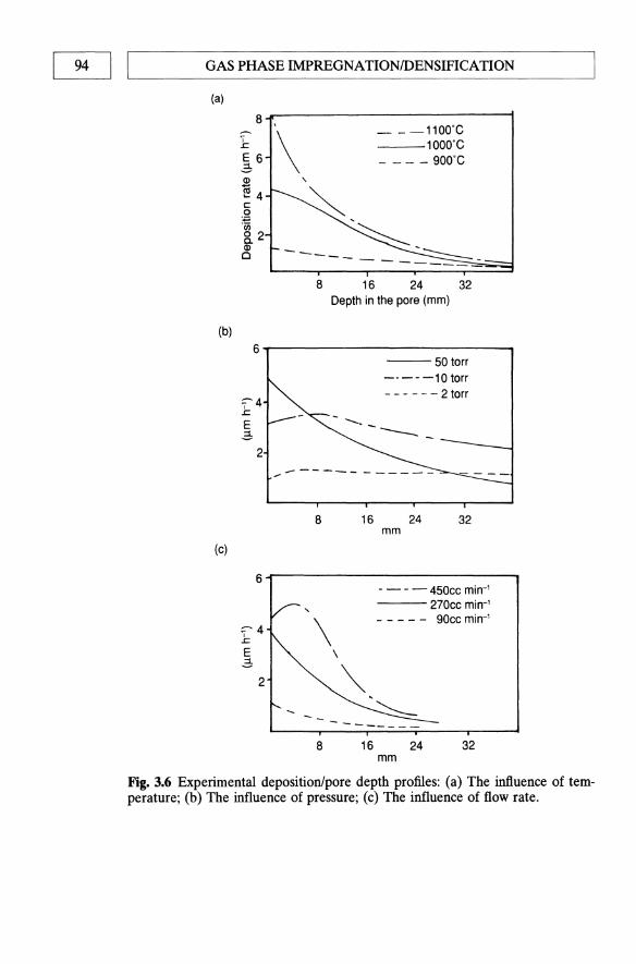
94 I I GAS PHASE IMPREGNATIONIDENSIFICATION
(a)
(b)
8 ~
I ..c: E 6 ~ Q)
iii .... 4 c: 0
~ 8. 2 Q) 0
6
:;--4 ..c: E .:;
2
\ __ -1100'C
1000'C - - - - 900'C
,
~ ~ --- ::::::::::::----------
8 16 24 32 Depth in the pore (mm)
---50 torr ---- -10 torr - - - - - - 2 torr
Fig. 3.6 Experimental deposition/pore depth profiles: (a) The influence of temperature; (b) The influence of pressure; (c) The influence of flow rate.

EXPERIMENTAL CVD TECHNIQUES I I 95 ~--------------------------------------------------~
substrate
1_-(jn]or\lt~ susceptor
Hydrocarbon
Fig. 3.7 The isothermal method of CVD processing.
3.3.2 The isothermal method
The isothermal method is a simple technique whereby a substrate is placed into an even temperature furnace and the reactant gases passed over it (Fig. 3.7). One thus relies on diffusion in and out of the pores. To avoid sealing the pores off at the mouth, the surface reaction rate must be kept lower than the diffusion rate. Unfortunately this means that the rate of weight gain is very slow, and process times become very long. An additional problem is that the rate of densification slows down as the amount of porosity decreases, making full densification virtually impossible. Figure 3.8 shows the weight/time graph for the densification of a porous carboncarbon billet with boron nitride (from BF3/NH3) as measured by Naslain and co-workers at Bordeaux/Societe Europeenne de Propulsion (SEP) [15]. The graph clearly shows the rate of weight gain to drop as the composite approached full densification. Inevitably, selection of isothermal CVD experimental parameters reflects a compromise between obtaining welldensified materials and working at an economically viable deposition rate.
The isothermal process, despite its fundamental limitations, remains in widespread use for composite production. The process is readily amenable to scale-up, with large furnaces capable of processing several objects simultaneously. In practice, carbon-carbon billets are processed for up to a week, removed from the furnace, the surface machined to remove the surface blockage of the pores, and then redensified in the CVD furnace.

96 II '-____ G_A_S_P_HA_S_E_IM_PRE_G_N_A_T_I_O_N_ID_E_N_S_IFI_C_A_TI_O_N ___ -----'
BN ex B~ I NH3 .1150·C. 0.26 bar 60
40 80 120 TIME (hours)
Fig. 3.8 Weight gain/time graph for the densification of a carbon skeleton with boron nitride.
This cycle sometimes has to be repeated three or four times. As a result, processing can often take up to a month or more, despite the use of low deposition pressures and diluent gases to minimize pore blockage by aiding diffusion.
3.3.3 The thermal gradient method
The thermal gradient method is another diffusion-controlled process. A temperature gradient is deliberately set up across the fibre preform, so that surface deposition of the material, and hence overcrusting, is avoided. In practice, a fibre preform is applied to a mandrel (often by winding). The mandrel (generaly solid graphite) acts as a susceptor material for inductive heating. A typical experimental set-up is shown in Fig. 3.9. By choosing the appropriate temperature, thermal conductivity of the preform and precursor gas flow rate, one can ensure that deposition occurs only on the hot mandrel/fibre interface region. In this way, the deposited matrix moves progressively out towards the outside surface of fibre preform.
There are two significant experimental points in discussing thermal gradient methods. Firstly, the fibre preform must possess a low thermal conductivity to allow the thermal gradient to be established; secondly, high gas flow rates must be used (generally a mixture of methane and nitrogen is used). These two factors ensure that a large thermal gradient occurs across the fibre preform, with a gas flow sufficient to cool the exterior surface of the preform. Temperature differences of up to 500 'C across a 1 cm thick preform have been observed [16]. Carbon felts are commonly used as substrates as they have considerably lower thermal conductivities than woven fabric structures.
The presence of a thermal gradient allows considerably higher deposition
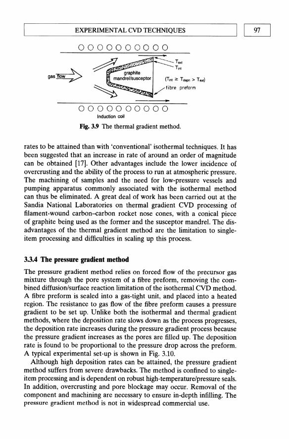
~ __________ E_XP_E_R_I_M_E_N_T_A_L_C_V_D __ TE_C_H_N_I_Q_U_E_S __________ ~I I 97
0000000000
gas~
0000000000 Induction coil
Fig. 3.9 The thermal gradient method.
rates to be attained than with 'conventional' isothermal techniques. It has been suggested that an increase in rate of around an order of magnitude can be obtained [17]. Other advantages include the lower incidence of overcrusting and the ability of the process to run at atmospheric pressure. The machining of samples and the need for low-pressure vessels and pumping apparatus commonly associated with the isothermal method can thus be eliminated. A great deal of work has been carried out at the Sandia National Laboratories on thermal gradient CVD processing of filament-wound carbon--carbon rocket nose cones, with a conical piece of graphite being used as the former and the susceptor mandrel. The disadvantages of the thermal gradient method are the limitation to singleitem processing and difficulties in scaling up this process.
3.3.4 The pressure gradient method
The pressure gradient method relies on forced flow of the precursor gas mixture through the pore system of a fibre preform, removing the combined diffusion/surface reaction limitation of the isothermal CVD method. A fibre preform is sealed into a gas-tight unit, and placed into a heated region. The resistance to gas flow of the fibre preform causes a pressure gradient to be set up. Unlike both the isothermal and thermal gradient methods, where the deposition rate slows down as the process progresses, the deposition rate increases during the pressure gradient process because the pressure gradient increases as the pores are filled up. The deposition rate is found to be proportional to the pressure drop across the preform. A typical experimental set-up is shown in Fig. 3.10.
Although high deposition rates can be attained, the pressure gradient method suffers from severe drawbacks. The method is confined to singleitem processing and is dependent on robust high-temperature/pressure seals. In addition, overcrusting and pore blockage may occur. Removal of the component and machining are necessary to ensure in-depth infilling. The pressure gradient method is not in widespread commercial use.
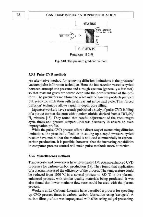
98 I LI ____ G_A_S_P_H_A_S_E_IM_PR_E_G_N_A_T_I_O_N_ID_E_N_S_IF_IC_A_T_I_O_N ___ ---'
gas flOW::> ~
ELEMENTS
Pressure ~ > ~ Fig. 3.10 The pressure gradient method.
3.3.5 Pulse CVD methods
An alternative method for removing diffusion limitations is the pressure/ vacuum pulse infiltration technique. Here the hot reaction vessel is cycled between atmospheric pressure and a rough vacuum (generally a few torr) so that reactant gases are forced deep into the pore structure of the preform. The precursors are allowed to react and the gaseous products pumped out, ready for infiltration with fresh reactant in the next cycle. This 'forced diffusion' technique allows rapid, in-depth pore filling.
Japanese workers have recently published a study of pulse CVD infilling of a porous carbon skeleton with titanium nitride, derived from a TiCl4/N2/
H2 mixture [18]. They found that careful adjustment of the vacuum/gas cycle times and process temperatures was necessary to ensure an even impregnation profile.
While the pulse CVD process offers a direct way of overcoming diffusion limitations, the practical difficulties in setting up a rapid pressure cycled reactor have meant that the method is not used commercially in carboncarbon production. It is possible, however, that the increasing capabilities in computer process control will make pulse methods more attractive.
3.3.6 Miscellaneous methods
Trinquecoste and co-workers have investigated DC plasma-enhanced CVD processes for carbon-carbon production [19]. They found that application of a plasma increased the efficiency of the process. The temperature could be reduced from 1050 ·C in a normal process to 850 ·C in the plasmaenhanced process, with similar quality materials being produced. It was also found that lower methane flow rates could be used with the plasma process.
Workers at Le Carbone-Lorraine have described a process for speeding up CVD process times in carbon-carbon fabrication using 'aerogels'. A carbon fibre preform was impregnated with silica using sol-gel processing.

'--__ C_V_D_PR_O_C_E_S_S_IN_G_O_F_C_A_R_B_O_N_-_C_A_R_B_O_N_C_O_M_PO_SI_TE_S _----'I 1 99
Pore-mouth diameter
r:
Pimth Graphitized
~JJt~'j~3Jht////. W ~ -~ ~~ Pitch impregnated HTT 2500'C
Cured Resin Graphitized ~;~/~;;;;/J.,////, ReSin Carbon
~~ --~
~ Resin impregnated
Pyrolytic Graphitized
~,19;/~///h m ~~ --~- ~
Early stages of Final stage of gas gas impregnation impregnation after
HTT 2500'C
Fig. 3.11 Carbon pore-filling mechanisms.
The gel was dried under critical pressure-temperature conditions to provide a highly microporous silica aerogel around the carbon fibre preform [20]. Deposition of carbon (from methane at 1000 ·C, 0.01 atm) led to the densification of the composite in a much reduced processing time. The silica aerogel was removed by sublimation of the silica at 2500 .c.
3.4 CVD PROCESSING OF CARBON-CARBON COMPOSITES
Carbon-carbon composites are generally processed in one of three ways (or a combination):
1. CVD processing; 2. multiple impregnation-pyrolysis using thermosets (e.g. phenolics)
(Chapter 4); 3. multiple impregnation-pyrolysis using thermoplastics (e.g. pitch)
(Chapter 5).
Figure 3.11 depicts the pore-filling mechanisms for the three methods [21].

100 II '-____ G_A_S_P_HA_S_E_IM_PRE_G_N_A_TI_O_N_fD_E_N_S_IFI_C_A_T_I_O_N ___ ----'
Table 3.1 Comparison of matrix formation techniques
Tensile Flexural Shear Density strength strength strength
Material (g cm-3) (MPa) (MPa) (MPa)
Resin impregnated with pyrolysis 1.65 82.7 68.9 27.6 CVD 1.50 120.6 142.6 51.7
3.4.1 Comparison of carbon-carbon matrix formation techniques
In theory, CVD-derived carbon is likely to possess greater mechanical strength than either the needle-like cokes derived from mesophase pitch pyrolysis or the amorphous glassy carbons derived from thermosetting resin pyrolysis [17]. The steady build-up of the matrix carbon around the fibres during the CVD process does not generate the severe fibre-matrix interfacial stresses seen with the phenolic resin impregnation-pyrolysis method. In fairness, it should be pointed out that although CVD-processed composites have excellent properties, the majority of composites are produced at least partially via impregnation-pyrolysis routes for the sake of process economics.
A number of studies have directly evaluated the relative merits of different carbon matrix formation techniques for the same fibre preform. McAllister and Taverna compared resin impregnation-pyrolysis cycles to CVD as a processing technique for the same 3-D preform. The mechanical properties of the composites are summarized in Table 3.1 [22].
Although the properties of the CVD-processed composite are superior to the resin-based composite, the authors do comment that some of the disparity can be explained by the absence of a graphitization stage in the CVD fabrication. Graphitization generally increases the oxidation resistance and density of a composite, but reduces its strength.
In another more thorough study, Mullen and Roy fabricated 3-D carboncarbon rings by a range of different processes [23]. The variation of mechanical properties with process technique is shown in Table 3.2. Several points of interest arise from these data. The two methods of CVD used, isothermal and pressure gradient, resulted in very different products being produced. The pressure gradient densified material had a relatively low density (1.28 versus 1.59 g cm-3 for the isothermal method product), but possessed a higher breaking stress. It is also significant to note that the supplementary use of a phenolic impregnation-pyrolysis cycle to densify the CVD-produced composites resulted in considerable increase in density (1.59 ~ 1.73 g cm-3 for the isothermal sample, 1.28 ~ 1.58 cm-3 for the pressure gradient material), but did not appear to be of benefit mechanically. This is somewhat at odds with later findings. In general, the authors

Tab
le 3
.2 M
echa
nica
l p
rop
erty
pro
cess
rel
atio
nshi
ps f
or 3
-D c
arb
on
-car
bo
n h
oo
ps
[23]
Impr
egna
tion
tec
hniq
ue
Phe
noli
c H
igh-
mel
t pi
tch
Low
-mel
t pi
tch
Isot
herm
al C
VD
Is
othe
rmal
CV
D/p
heno
lic
Dif
fere
ntia
l pr
essu
re C
VD
D
iffe
rent
ial
pres
sure
CV
D-g
rap
hit
ized
D
iffe
rent
ial
pres
sure
CV
D-p
heno
lic
Den
sity
(g
cm
-3)
1.62
1.
64
1.65
1.
59
1.73
1.
35
1.28
1.
58
Ten
sile
st
reng
th
(MP
a)
118.
5 94
.4
128.
2 11
3.7
106.
8 13
6.4
130.
2 12
8.2
Ten
sile
m
od
ulu
s (G
Pa)
70.3
10
6.1
64.1
77
.2
77.9
68
.2
61.3
64
.1
Stra
in t
o fa
ilur
e (%
)
0.18
0.
08
0.05
0.
15
0.13
0.
20
0.20
0.
20
(') a '"d
::0
0 (')
trI
en
......
Z
Com
pres
sive
C
ompr
essi
ve
Stra
in t
o
I~ st
reng
th
mo
du
lus
fail
ure
(MP
a)
(GP
a)
(%)
~ 52
.9
20
0.59
11
;; 0 Z
103.
1 33
.8
0.48
I~ 73
.9
27.6
0.
40
115.
1 23
.4
0.72
0
82.7
18
.6
0.65
I
Z
(') 0 s= '"d
0 en
...... til en ~

102 1 ,-I ____ G_A_S_PH_A_SE_IM_P_RE_G_N_A_T_I_O_N_ID_E_N_S_IF_I_CA_TI_O_N ___ _
Table 3.3 Mechanical property data for Le Carbone-Lorraine CVD processed carbon-carbon [24]
Aerolor 32 Aerolor 33
Density (g cm-3) 1.6-1.7 1.8-1.9 Flexural strength: XY (MPa) 80 40
Z (MPa) 80 60
Tensile strength: XY (MPa) 70 70 Z (MPa) 70 110
Tensile modulus: XY (GPa) 50-70 70 Z (GPa) 50-70 120
Compressive strength: XY (MPa) 50-80 100 Z (MPa) 50-80 100
CTE ('C-1) 3 4
Thermal conductivity (W m-1 c-1) 10 120
suggested that the better mechanical properties of the CVD-processed composites were a result of the superior fibre-matrix interactions.
A more recent study by Girard and Slonia at Le Carbone-Lorraine provides further information on the use of an impregnation/pyrolysis step after CVD processing [24]. The mechanical property data of two products, Aerolor 32, produced by CVD processing of a 3-D fibre preform, and Aerolor 33, produced by a combined CVD-impregnation/pyrolysis method on a similar preform, are shown in Table 3.3.
In contrast to the results of Mullen and Roy, the data in Table 3.3 convincingly show the densification of a CVD-processed composite by impregnation-pyrolysis to improve the mechanical properties. The tensile and compressive properties benefit particularly, although the flexural properties are diminished. Of particular interest is the significant increase in thermal conductivity on impregnation-pyrolysis of the CVD-fabricated composite. The thermal conductivity of the composite is clearly influenced by the residual porosity.
Two studies have considered the effect of a CVD processing step after impregnation-pyrolysis processing of a carbon fibre preform. McAllister and Lachmann compared the properties of phenolic-based 3-D carboncarbon materials, with and without additional CVD processing, with the properties of pitch-derived composites [25]. Table 3.4 shows that the CVD process markedly improves the strength of the phenolic-derived material, presumably by removing the residual porosity that acts to increase stress concentration in the matrix material (and hence reduce breaking stresses). It is noticeable, however, that the mechanical properties of the two pitch-derived composites (one from a cinnamalydehyde-indene synthetic

L-__ C_VD_P_R_O_C_E_S_SI_N_G_O_F_C_A_RB_O_N_-_C_A_RB_O_N_C_O_MP_O_S_lTE_S __ ----'1 I 103
Table 3.4 Comparison of matrix formation techniques for 3-D carbon-carbon composites [25]
Flexure Flexure Compressive Compressive strength modulus strength modulus
Material (MPa) (GPa) (MPa) (GPa)
Phenolic 89.0 27.6 56.5 7.6 Phenolic and CVD 108.9 24.1 73.0 6.9 CAl 102.7 32.4 50.3 6.9 LTV pitch 153.6 32.4 71.7 10.3
pitch (CAl), the other from an LTV proprietary pitch, see Chapter 10) are better than the phenolic derived composites (especially the LTV synthetic pitch). The LTV pitch was specifically designed to give good fibre/matrix interfacial properties, and the success of the design is evident from the mechanical property data.
Hill and co-workers at A WRE, Aldermaston studied thermal gradient CVD as a method of densifying and strengthening unidirectional (ID) phenolic-derived composites [26]. When untreated carbon fibres were used in the phenolic prepreg, very little fibre/matrix adhesion was observed. As a result, the material had, on pyrolysis, little adhesion between the carbon fibres and glassy carbon matrix. The CVD densification of this 'first pass' material resulted in considerable pore infilling, especially at the fibre/matrix interface, and gave a considerable improvement in longitudinal flexural properties. The authors comment that using CVD-derived pyrolytic carbon to fill the spaces around the fibre results in composites capable of dissipation of fracture energy by fibre pull-out. Pyrolytic carbon possesses the optimum shear properties, and adhesion to both the phenolic-derived glassy carbon and the untreated carbon fibre surface, to ensure good fracture toughness.
Finally, Seibold at McDonnell Douglas has evaluated CVD (CH 4 at 1100 DC) as an intermediate process cycle in the multiple impregnationpyrolysis processing of high-density 3-D carbon-carbon materials [27] (up to 15 cycles used). He found that application of initial CVD process steps limited the final density attainable after multiple cycles to 1.83 g cm-3• The density limitation was caused by the creation of closed porosity during the initial CVD step. Intermediate CVD processing was found to be no more effective than conventional resin impregnation-pyrolysis for further densification. Seibold concluded that CVD processing is not worth while.
A proviso should be added, however, that by operating the CVD methane cracking process at 1100 DC, one might well be handicapping the final result by sealing in closed pores. The use of more 'gentle' experimental conditions might well result in better composite properties.

104 I IL--___ G_A_S_P_H_A_S_E_I_M_P_R_E_G_N_A_T_IO_N_ID_E_N_S_IF_IC_A_TI_O_N ___ -------'
~ .. ,~~;j~~~r- Carbon fibre
(a)
Carbon fibres
(b)
• • __ -+--Carbon fibres
• • (e)
Fig. 3.12 CVD-derived carbon microstructures: (a) rough laminar; (b) smooth laminar; ( c) isotropic.
3.4.2 Carbon matrix microstructure: the inftuence of process conditions
Early work on pyrolytic carbon deposition in fluidized beds established that several different morphologies of CVD-deposited carbon can be produced. Three types of carbon microstructure are commonly seen in CVD composite fabrication experiments:
1. smooth laminar 2. rough laminar 3. isotropic
These microstructures are characterized by their optical activity under polarized illumination; schematic depictions of their optical activities are shown in Fig. 3.12.
Several research groups have performed experimental studies to elucidate the experimental conditions which control the microstructure of the deposited carbon by careful variation of pressure, temperature, gas flow rates and precursor nature, etc. Trinquecoste and his team studied the microstructures of carbons derived from methane over a range of conditions [28], while Kimura et al. studied the microstructures of propane-derived

'--__ C_VD_P_R_O_C_E_S_SI_N_G_O_F_C_A_RB_O_N_-_C_A_RB_O_N_C_O_M_P_O_S_ITE_S_------.JI I 105
carbons [29]. Both groups observed transitions from one microstructure to another as conditions changed.
Liebermann and Pierson at the Sandia National Laboratories have developed a chemical model for the CVD of carbon which rationalizes the observed microstructure/experimental correlations. They postulated that methane decomposes to give either ethyne (acetylene) (C2H 2) or benzene (C6H6). These two species act as precursors to the elemental carbon formed in the deposit. As previously stated, acetylenic precursors are thought to be responsible for isotropic carbon, whereas aromatic precursors, such as benzene, are thought to be responsible for smooth laminar carbon [9]. Thermodynamic calculations based on experimental pressures, temperatures and gas flow/composition were performed and the types of carbon deposit successfully correlated with the equilibrium predicted ratios of acetylene/benzene concentrations. The results and conclusions are summarized as follows [30]:
1. smooth laminar - low deposition temperature, high partial pressure CH4, no added H2, [C2H2] : [C6H6] < 5;
2. rough laminar - intermediate deposition temperature, intermediate partial pressure, some added H2, [C 2H2] : [C6H6] > 5, < 20;
3. isotropic - high deposition temperature, low partial pressure C~, large amount of added H2, [C 2H 2] : [C6H6] > 20.
Liebermann and Pierson carefully studied the microstructures of the CVD matrices produced over a wide range of conditions using the thermal gradient CVD technique (the thermal gradient technique allows considerable variation of experimental parameters without causing the sealing of pores). They noticed that the matrix microstructure generally changes across a sample. The changes were always smooth laminar ~ rough laminar, or rough laminar ~ isotropic, consistent with the model developed. In fact, it was found to be very difficult to deposit carbon in one particular microstructure throughout the preform. Deviations from their theoretical model occurred whenever the conditions were a long way from equilibrium, such as at high flow rate.
Given that the CVD process offers some degree of manipulation of the matrix microstructure, what is the optimum type of microstructure for a carbon-carbon composite? Granoff and co-workers concluded that a rough laminar was the preferred microstructure. Isotropic carbon was found to be relatively low in density and the smooth laminar carbon was shown to be prone to thermal stress microcracking [31]. Liebermann et al. were subsequently able to fabricate a PAN-derived carbon felt/CVD carbon composite with a matrix consisting of 90% rough laminar carbon. The material was found to have excellent thermal and mechanical shock resistance [32]. Yasuda and co-workers have fabricated carbon-carbon materials using the pressure gradient method. Under a variety of different

1~ I ~I _______ G_A_S_P_H_A_S_E_I_MP __ R_E_G_N_A_T_IO __ N_ill_E_N_S_IB_C_A_TI __ O_N ______ ~ experimental conditions, they produced two types of composite matrix: a combination smooth/rough laminar matrix, and a combination rough laminar/isotropic one. The rough laminar/isotropic matrix was found to possess superior strength and stiffness. The smooth/rough laminar matrix composite, on the other hand, possessed excellent toughness which was attributed to the energy-absorbing properties of the network of thermal stress cracks in the smooth laminar matrix, leading to a less brittle failure mode.
It is worth noting that the temperature and pressure gradient methods allow considerable freedom in the selection of experimental conditions for CVD carbon deposition. A choice of microstructure can therefore be made. By contrast, the isothermal process requires operation under quite a narrow range of conditions in order to satisfy the diffusion rate/surface reaction rate criteria previously discussed. As a result, the choice of microstructure is very much narrower. Under typical industrial operating conditions (20 torr CH4 at 1050 0c) the matrix possesses a predominantly smooth laminar microstructure. Raising the temperature to promote the rough laminar structure would result in the formation of undesired closed porosity.
3.4.3 Fibre preform geometry/CVD process relationships
The nature of the fibre substrate, be it a woven long-fibre multidimensional structure or a compacted carbon felt substrate, will greatly influence the final mechanical properties of the composite. In addition, each fibre substrate will have a defined pore size distribution, which will affect the process conditions required for successful densification.
Conventional composite theory leads one to expect the mechanical properties of a composite to increase with increasing volume fraction of reinforcing fibre. This is not necessarily the case with CVD-processed carbon--carbon. One might predict that low fibre content materials can be processed to higher densities with the high density of pyrolytic carbon relative to carbon fibre. A carbon felt preform of initial density of 0.1 g cm-3 for example, can be processed to a density of 2.06 g cm-3, whereas a long-fibre 2-D preform of density 1 g cm-3 (58% v/v) can be processed to a density of only 1.6 g cm3• A high initial fibre content means that the initial pores are a good deal smaller and therefore more prone to sealing, thus causing poor mechanical performance. Kotlensky and Bauer found that the mechanical properties of a series of CVD-processed eight-harness satin weave preforms did not increase as the fibre volume increased from 34 to 70%. High fibre content materials generally exhibited lower densities and lower flexural strengths than the low fibre content preform-derived composites [33].
Collaborative work between teams at the Sandia and Oak Ridge National Laboratories has further illustrated the effect that initial porosity

'--__ C_V_D_PR_O_C_E_SS_IN_G_O_F_C_E_R_A_M_I_C_M_A_T_R_IX_C_O_M_PO_SI_TE_S_-,I I 107
can have on the properties of CVD-processed carbon-carbon materials [34]. They prepared two types of filament-wound preform - one with wound yam (each yam consisting of up to 2500 carbon fibres) and the other with the same wound yam arrangement with additional short chopped fibres sprayed on to the preform during the filament winding stage. These chopped fibres served to reduce considerably the macropore size between the wound yams. The two types of preform were densified by thermal gradient techniques and subjected to mechanical and pore size testing. The addition of chopped fibres was found to reduce considerably the number of large pores and, accordingly, boost the mechanical performance of the composite.
Kotlensky identified different mechanical property characteristics of CVD-processed carbon-carbons produced by different CVD processes [17]. Comparison of the isothermal and temperature gradient CVD methods for the formation of a matrix around filament-wound yam preforms showed the isothermal method to be superior at filling the small pores in between the individual fibres; the thermal gradient method preferentially filled the large pores. One study has evaluated the effect of the CVD process type used on the mechanical properties of the resulting composite. Using a carbon felt substrate, the isothermal method was found to produce the highest flexural strength materials [16] even though thermal gradient processed materials possessed equivalent densities. It appears that the residual porosity left in the thermal gradient processed material is more detrimental than that remaining in the isothermally processed composite.
Finally, it is instructive to consider how scale-up can cause the need for a change of process conditions. Workers at the General Electric Company noted that it was necessary to change the CVD conditions (to a longer deposition time and lower operating pressure) in order to achieve successful densifieation of a 20 x 20 x 30 em fibre preform in comparison with a 10 X 10 x 20 cm preform. It is noteworthy that CVD processing is only really cost-effective for relatively thin preforms - a thick preform places too many demands on the diffusion-controlled stage.
3.5 CVD PROCESSING OF CERAMIC MATRIX COMPOSITES
3.5.1 Introduction
The excellent high-temperature strength, oxidation resistance and toughness of well-processed ceramic matrix composites make them extremely attractive materials for high-temperature environments. A specific example of an area where ceramic matrix composites might be deployed is in the fabrication of jet turbine blades. The insidious increase in temperature of the nickel alloys in current use, place restrictions on the operating temperature of the turbine. Processing by CVD represents a viable method for matrix formation - the relatively low temperatures involved do not

108 I LI ____ G_A_S _PHA __ SE_IM_P_RE_G_N_A_T_I_O_N_ID_E_N_S_IF_I_CA_TI_O_N ___ ---'
cause fibre degradation, processing to high densities can be achieved and the process yields very pure materials (if the thermodynamic constraints discussed in Section 3.2.1 are considered). For the high-temperature refractory materials, such as SiC and TiC, other composite fabrication techniques based on hot pressing/sintering or melt infiltration are not applicable, and CVD is the preferred fabrication technique. One of the great advantages of CVD fabrication for carbon-carbon over rival processing routes is its versatility. The same equipment can be used to deposit carbon, ceramic or hybrid matrices and to produce oxidation-protective coatings.
3.5.2 Hybrid carbon fibre/ceramic matrix compounds produced by CVD
A major contribution to this field has been made by the group led by Naslain at CNRS (Bordeaux)/SEP, which have made great strides in understanding the fabrication processes and mechanical behaviour of ceramic matrix composites [35]. A great deal of this work has been concerned with upgrading the mechanical and oxidation resistance properties of CVDproduced carbon--carbon. Partially densified carbon fibre-CVD carbon materials were densified with a number of CVD-derived ceramics to different levels of final residual porosity. Systematic studies of the mechanical, chemical and thermal properties as a function of the ceramic content were carried out.
The first published study concerned the formation and properties of C-C/SiC and C-CrriC composites [3). Thermodynamic calculations were used to set the inlet flow conditions to produce pure SiC (from CH3SiCl31 Hz) and TiC (from TiCI4/CILlHz). A low-temperature, low-pressure experimental set-up was utilized to ensure in-depth deposition throughout the pore system. The experimental conditions (temperature, pressure, flow rate) were optimized by the use of Si microprobe analysis on cross-sections of materials produced under different conditions. Silicon microprobe analysis showed that if the deposition rate was too high (due to temperature, pressure or flow rate being too high), overcrusting occurred rapidly, with very little SiC being deposited within the inner part of a cylindrical 2-D carbon--carbon preform. The rate of SiC deposition was found to be slightly greater than that of the carbon deposition; the rate of TiC deposition was, however, much slower.
All of the studies were based on a 2-D PAN-derived carbon fibre preform, densified with CVD carbon to a residual porosity of around 35%. These preforms were then densified with varying amounts of SiC or TiC up to full densification, and the mechanical and chemical properties studied as a function of the ceramic content. Linear increases in compressive strength (afl) and modulus (Efl) were noted with increasing SiC or TiC contents. Of particular interest are the mechanical properties of the fully densified C-c/SiC and C-CrriC composites in comparison with a fully

L-__ C_VD_P_R_O_C_E_S_SI_N_G_O_F_C_E_RAM __ I_C_MA_T_R_IX_C_O_M_P_O_S_lTE_S_----.l1 I 109
Table 3.5 Mechanical properties of carbon/ceramic hybrid matrix composites
Ratio of carbon fibre to ceramic EI1 0'11 matrix (GPa) (MPa)
C-C 10 100 C-c/SiC 5:7 51 310 C-c/TiC 5:7 48 330
densified carbon-carbon composite (since all of the materials are based on similar PAN-carbon fibre preforms, with 40% of the total composite volume being fibre). The mechanical property data are shown in Table 3.5 [3].
The mechanical properties are clearly improved by partial substitution of a carbon matrix with either of the carbides. The composite materials fail in different modes depending on the volume of carbide present. At low carbide content, failure occurs by delamination, whereas at higher carbide content failure occurs by combined fibre/matrix fracture.
A more complete mechanical analysis of the C-ClTiC system is given in a follow-up paper by the same authors [36]. The oxidation resistance of these materials was studied and correlated with oxidation conditions (temperature and partial pressure of oxygen) and degree of carbide infiltration. The C-C/TiC composites initially showed a weight gain on oxidation, due to the formation of Ti02, followed by a loss in weight as oxidation of the carbon occurred. The transition from weight gain to weight loss regimes occurred more rapidly as the temperature increased. As expected, increasing the level of TiC infiltration increased the oxidation resistance. The C-C/SiC composites exhibited the best oxidation resistance of all. The fully densified C-C/SiC materials showed reasonable oxidation resistance up to 1600 ·C, at which temperature the SiC began to oxidize and vaporize.
A similar study has been performed on a series of C-CIB4C materials [37]. A C-CIB4C composite, with a matrix carbon: matrix carbide ratio of 5: 7, was found to possess a compressive strength of 310 MPa, i.e. similar to the C-C/SiC and C-ClTiC materials. The degree of oxidation resistance was found to be on a par with the C-ClTiC material, but inferior to the C-C/SiC material.
To complete the series of ceramic substitution materials, Naslain and co-workers prepared and studied a series of C-CIBN hybrid matrix composites using similar techniques [15]. The boron nitride was deposited using low-pressure CVD from a BF3INH3 mixture. The mechanical properties of C-CIBN composites were found to be inferior to those of the related C-C materials, a consequence of the low modulus of BN. The oxidation resistance of the C-CIBN materials was, however, found to be superior to the C-C analogues. Above 900 ·C, weight increases occurred

110 1 ,-I ____ G_A_S_P_H_A_S_E_IMP_R_E_G_N_A_T_I_O_N_ID_E_N_S_IF_IC_A_TI_O_N ___ -----'
40
€"' 20 C/SiC (CVO)
1--_______ 20 SiC/SiC (CVO) -E 301---------f iii Q.
~ :g 20 CD
~ r-X __ X__ 10 SiC/SiC (CVO) ~ 10 X -X-X;::- __ a.-SiC
f---------- ---
400 800 1200 1600 2000 Temperature (K)
Fig. 3.13 The temperature dependence of fracture toughness of silicon carbide composite materials.
due to the formation of B20 3• At higher temperatures, the oxidation resistance of the C-CIBN material diminished, due to the volatilization of B20 3 which becomes appreciable at temperatures above 1100 .c.
3.5.3 CVD Ceramic Matrix Composites
Despite a well-established technology for producing CVD ceramic coatings, relatively little work has been done on the fabrication of ceramic matrix composites. The best studied matrix system is silicon carbide from which excellent results have been obtained. A 2-D SiC-SiC composite has entered commercial production [38]. The material is unusual in that the matrix (CVD-SiC) is stiffer than the fibres (Nicalon SiC fibres). The SiC fibres generally used are produced by the pyrolysis of a spun carbosilane fibre and contain substantial inclusions of Si02 and C. The toughness/temperature curves for the SEP range of SiC matrix composites are shown in Fig. 3.13. Of note is the high toughness of the SiC/SiC and C/SiC materials relative to sintered, monolithic SiC (carborundum). The SiC-SiC composite is reputed to possess the highest toughness yet observed for any ceramic material [35].
Observation of the fracture pattern of the SiC-SiC composites explains their high toughness. Stress relief occurs via matrix microcracking, allowing for the tensile strain to failure to be increased from around 0.08% in monolithic SiC to 0.6% in the composite. The process conditions used by SEP in the fabrication of their composites have been disclosed in a patent [39]. The furnace operating temperature is 900 ·C, and the partial pressures of H2 and MeSiCl3 and 15 are 5 torr respectively.

L-__ CVD __ P_R_O_C_E_S_SIN_G_O_F_CE_R_AM __ IC_M_A_TR_I_X_C_O_M_P_O_S_lTE_S_------'1 I 111
Fitzer and Gadow have performed several studies on SiC matrix composites, comparing CVD as a matrix fabrication technique with reaction bonding [40]. Reaction bonding is a fast and simple technique. A porous carbon body is dipped into molten silicon and heat treated to form a silicon carbide matrix. Fitzer concluded that CVD-fabricated composites possessed far superior mechanical properties (up to 50-80% better) than the reaction-bonded materials. He also showed that extemely high flexural strengths could be achieved using CVD-derived SiC fibres, rather than the more widespread organometallic polymer-derived 'Nicalon' SiC fibres. At high temperatures, however, the 'Nicalon' SiC fibres degraded slightly to weaken the interfacial fibre-matrix bond, so that the 'Nicalon' SiC-derived composites exhibited a less brittle, tougher fracture mode. Fitzer has also performed several studies on the use of CVD for strengthening SiC and reaction-bonded Si3N4 monoliths [14]. While in-depth infiltration of the SiC body with SiC was quite simple, the rapid formation of Si3N4 (from SiCI4INH3), even at low temperatures, meant that the porous Si3N4 body could not be effectively densified.
Workers at the Oak Ridge National Laboratories in the USA have developed a novel pressure/temperature gradient process for CVD fabrication of ceramic matrix composites [41]. In this method, a fibre preform is placed in a gas-tight die, so that a pressure gradient can be applied across it. The unit is then placed into one end of a hot zone, to provide a combined pressure/temperature gradient. The experimental set-up is shown in Fig. 3.14. Considerable success was achieved in densifying SiC fibre (or whisker) preforms with SiC (from CH3SiCI3IHz) and Si3N4 (from SiCI4/ NH3); a SiC/SiC composite was processed in 12 h, a considerable improvement on conventional isothermal method process times (i.e. 150 h for Fitzer/Gadow) [40]. I-D and 2-D SiC-SiC composites have been made using this SiC-SiC method. The I-D composites were found to possess a flexural strain to failure of 1 %. Examination of the fracture faces showed that extensive fibre pull-out had occurred, indicative of a well-processed material with the optimum level of fibre-matrix adhesion. It is interesting to note that the Oak Ridge workers have recently used the temperature/pressure gradient method to make lightly densified, porous ceramic whisker/ ceramic matrix composites which they have successfully tested as hightemperature filter materials [42].
An interesting extension of the Oak Ridge CVD programme resulted from the accidental production of TiSiz/SiC dispersed phase composite. The aim was to produce a TiC/SiC material from a feed of TiCI4/CH3SiCI3IHz but kinetic factors precluded this aim. The fracture toughness of the TiSiz/ SiC material was found to exceed greatly that of pure SiC. The authors suggest that the TiSiz/SiC material might be very useful as an oxidationresistant coating for carbon-carbon composite materials.
Finally, Naslain and co-workers have recently reported the CVD

GAS PHASE IMPREGNATIONIDENSIFICA TION
Inlet gas lin > Tout !]>n > Paut
Heat Ing elements
Rbre preform
Water cooled holder
Fig. 3.14 The Oak Ridge National Laboratory combined pressure/temperature gradient CVD technique [41].
fabrication of an Al20 3-A120 3 composite [43]. The alumina matrix was formed from an AlCl3/C021H2 feed stream at working conditions of 975 'C and 2.5 kPa. The composite, densified to a 10% residual porosity, showed a very brittle mode of fracture, consistent with the strong fibre-matrix adhesions present.
3.6 A BRIEF SURVEY OF COMMERCIAL CVD COMPOSITE FABRICATION PROCESSES
Fabrication of carbon-carbon materials by CVD has existed for nearly 20 years, in competition with the multiple resin impregnation-pyrolysis method. By contrast, CVD fabrication of ceramic composites is less widespread. The choice of CVD or impregnation-pyrolysis as a matrix fabrication method is influenced by many factors. The generally advantageous mechanical properties of CVD-derived carbon-carbon in comparison with thermoset-derived impregnation-pyrolysis materials can be offset by the long process times required. The CVD method tends to work best for relatively thin preforms, where the diffusion of gases to and from the middle of the preform is not too difficult.
In the UK, the Dunlop Aviation Division make carbon-carbon via CVD, the product being aimed almost entirely at the aircraft brake market (brake materials make up 63% of the total end market for carbon-carbon at

SUMMARY I I 113 L-________________________________________________ ~
present). The carbon-carbon is made via a low-pressure isothermal technique. After a slow build-up of matrix (up to a month), the material is graphitized at 2500 ·C and then machined for use. The key to commercially viable production obviously lies in a well-integrated production system and the use of large CVD furnaces to facilitate economies of scale. Dunlop have achieved the former by buying in PAN fibres for carbonization, layup and processing on-site, and the latter by a large-scale furnace investment programme. Arguably the world's leading nation in CVD composite fabrication technology is France, notably through SEP and Le CarboneLorraine. The former produce three types of composite material: SEPCARB, a carbon-carbon product aimed mainly at the brake materials market, SEPCARBINOX, a carbon-silicon carbide material designed for use in propulsion systems where the oxidation is too severe for conventional carbon--carbon, and CERASEP, a silicon carbide-silicon carbide material whose outstanding oxidation resistance and toughness have led to applications in engines and aerospace. Le Carbone-Lorraine has pioneered the use of CVD technology for the production of 3-D carbon-carbon with very high densities, used mainly for its excellent ablation properties. The two main German carbon companies (Schunk and Sigri) appear to make their carbon-carbon materials by resin impregnation-pyrolysis.
In the USA, a large amount of work on CVD fabrication of carboncarbon has been carried out at the Sandia National Laboratory, mainly aimed at fabricating filament-wound missile nose cones. A large number of companies h,ave used CVD for carbon-carbon fabrication - the SuperTemp division of BF Goodrich, LTV, Hitco, Bendix, ABS, GE and Avco [44]. It is hard to generalize on what the accepted route for C-C manufacture is in the US C-C industry; CVD is used either (a) when the product is manufactured on multiple-scale economics or (b) the outstanding properties of CVD carbon-carbon are necessary. It is significant to note that Du Pont have recently chosen to enter the high-temperature composites business by signing a technology licence agreement with SEP [45]. They aim to begin production by the early 199Os, with a view to supplying various US government aerospace and defence programmes. In view of the wide-ranging CVD fabrication technology for carbon-carbon that must be available in the USA, it appears likely that Du Pont are particularly interested in the CVD technology for silicon carbide materials, rather than carbon-carbon, alone.
3.7 SUMMARY
The fabrication by CVD of carbon--carbon composite materials offers considerable control over the matrix composition. The microstructure of the CVD-derived material can be controlled by the experimental

114 I LI ____ G_A_S_PH_A_SE_IM_P_RE_G_N_A_T_I_O_N_fD_E_N_S_IF_I_C_A_TI_O_N ___ ------.J
parameters - temperature, pressure, gas phase composition and flow rate, and even the fibre preform geometry. The CVD method has considerable advantages over the other fabrication techniques in that the same equipment may be used to deposit non-carbon oxidation inhibitors and coatings and to densify ceramic matrix composites as well as carbon and graphite. The successful densification of a composite material using CVD necessitates great care in the selection of experimental conditions which will allow the deposition of matrix material throughout the pore system of the fibre preform. It is a slow process that requires considerable skill. The conventional isothermal process, in which the fibre preform is placed in a uniform temperature/pressure furnace, must be operated under conditions where the surface nucleation and growth rates are slower than the gaseous diffusion rates, in order to avoid 'plugging' of the surface pores in the fibre preform. In practice, therefore, the equipment must be operated at low temperatures and pressures, thus depositing material at a low rate.
Experimental techniques exist to overcome the diffusion/surface kinetics limitations of the isothermal CVD process by the application of thermal gradients and/or forced gas flows to the fibre substrate. The majority of such methods are, unfortunately, not amenable to production scale-up. The isothermal method remains the most economical method for largescale CVD production of composites despite being beset with the problem of long processing times.
The CVD method produces good quality carbon-carbon materials. The technique is especially suited to the production of relatively thin artefacts, such as braking materials, where the diffusion problems are less severe. Many of the problems associated with the resin impregnation-pyrolysis route (Chapter 4), such as the severe thermal stresses generated in the composite during pyrolysis, are avoided with the CVD technique. The widespread use of CVD-fabricated carbon-carbon materials has to date been severely hindered by the cost when compared to material produced by other routes.
In many respects, CVD is the best developed of any of the production methods for high-temperature composites, especially carbon-carbon. It has proved to be the best method for the fabrication of long-fibre reinforced silicon carbide materials. The commercial SiC-SiC product, CERASEP, exhibits outstanding toughness for a ceramic material and seems to be on the threshold of widespread use as a material capable of operating in oxidizing environments up to 1350 0c.
REFERENCES
1. Bracke, P., Schurmans, H. and Verhoest, J. (1984) Inorganic Fibres and Composite Materials, (EPO App. Tech. Series, 3), Pergamon Press, Oxford.
L-_________________ RE __ F_E_RE __ N_C_E_S ________________ ~I I 115
2. Besmann, T. M. (1977) Oak Ridge Nat. Lab. Report, no. TM 5775 (April 1977). 3. Naslain, R, Rossignol, J. Y., Hagenmuller, P., Christin, F., Heraud, L. and
Choury, J. J. (1981) Rev. Chim. Miner., 18, 544. 4. Randich, E. and Gerlach, T. M. (1983) Chem. Tech., 102, 2. 5. Stinton, D. P., Lackey, W. J., Lauf, R J. and Besmann, T. M. (1984) Ceram.
Eng. Sci. Prod., 5, 668. 6. Spear, K. E. (1982) Pure Appl. Chem., 54, 1297. 7. Bokros, J. C. (1969) Chem. Phys. Carbon, 5, 1. 8. Noles, G. T. and Liebermann, M. L. (1975) 1. Chromatog., 114, 211. 9. Liebermann, M. L. (1972) Proc. 3rd Int. Conf on CVD, 3, 95.
10. Nuhara, K. (1984) Am. Ceram. Soc. Bull., 63, 1160. 11. Tesner, P. A, (1984) Chem. Phys. Carbon, 19, 65. 12. Van der Brekel, C. H. J. and Lersmacher, B. (1983) Proc. Eur. Conf CVD,4,
321. 13. Diefendorf, R J. and Sohda, Y. (1983) Ext. Abstr. Prog., 17th Biennal Conf
on Carbon, 17, 31. 14. Fitzer, E. and Hegen, D. (1979) Angew. Chem. Int. Ed., 18, 295. 15. Hannache, H., Quenisset, J. M., Naslain, Rand Heraud, L., J. (1984) Mat. Sci.,
19,202. 16. Kotlensky, W. V. (1971) Materials 71, SAMPE 16th Nat. Symp. Exhib., 16, 257. 17. Kotlensky, W. V. (1973) Chem. Phys. Carbon, 9, 173. 18. Sugiyama, K. and Nakamura, T. (1987) 1. Mat. Sci. Lett., 6, 331. 19. Lachter, A, Trinquecoste, M. and Delhaes, P. (1985) Carbon, 23, 111. 20. Pajonk, G. A and Teichner, S. J. (1986) Aerogels (Springer Proc. Phys., Vol.
6), Springer-Verlag, Heidelberg, p. 193. 21. Fiizer, E. (1987) Carbon, 25(2), 163. 22. McAllister, L. E. and Taverna, A R (1971) 10th Biennal Conf on Carbon,
Bethlehem, Pa, Paper no. FV-40. 23. Mullen, C. K. and Roy, P. J. (1972) Proc. 17th Nat. SAMPE Symp., III-A-2. 24. Girard, H. and Slonia, J. P. (1978) Proc. 5th Int. Conf on Carbon and Graphite,
1,483. 25. McAllister, L. E. and Lachmann, W. L. (1983) in Fabrication of Composites
(Handbook of Composites, Vol. 4) (eds A Kelly and S. T. Mileiko, Amsterdam, ch. 3, p. 109.
26. Boyne, L., Hill, J. and Turner, K. (1975) Proc. 5th Int. Conf CVD, 5, 577. 27. Seibold, R W. (1977) Ext. Abstr. 13th Biennal Conf on Carbon, 13, 404. 28. Delhaes, P., Trinquecoste, M., Pacault, A, Goma, J., Oberlin, A and Thebault,
J. (1984) Chimie Physique, 81, 809. 29. Kimura, S., Yasuda, E., Takase, N. and Kasuga, S. (1981) High Temp, High
Pressure, 13, 193. 30. Pierson, H. o. and Liebermann, M. L. (1975) Carbon, 13, 159. 31. Granoff, B. Pierson, H. O. and Schuster, D. M. (1973) Carbon, 11, 177. 32. Liebermann, M. L., Curlee, R M., Braaten, F. H. and Noles, G. T. (1975) 1.
Compo Mat., 9, 337. 33. Bauer, D. W. and Kotlensky, W. V. (1973) SAMPE Quart., 4, 10. 34. Brassell, G. W., Horak, J. A and Butler, B. L. (1975) 1. Compo Mat., 9, 228. 35. Naslain, R (1986) 1. Phys. Colloq., CI, 47, 703. 36. Rossignol, J. Y., Quenisset, J. M. and Naslain, R (1987) Composites, 18, 135.

116 I 1~ ______ G_A_S_P_H_A_S_E_I_M_P_R_E_G_N_A_T_IO __ N_m_E_N_S_IF_IC_A_T_I_O_N ______ ~ 37. Naslain, R and Langlais, F. (1985) Proc. 21st Univ. Con! Sci. Ceramics, Penn.
St. Univ. 38. SEP (1987) promotional literature. 39. SEP (1988) Fr. Demande, 2, 401, 888. 40. Fitzer, E. and Gadow, R (1986) Am. Ceram. Soc. Bull., 65, 326. 41. Caputo, A. J. and Lackey, W. 1. (1984) Ceram. Eng. Sci. Proc., 5,654. 42. Sheppard, L. M. (1987) Adv. Mat. Processes, 73,7. 43. Coimet, R, Lhermitt-Sebire, I. and Naslain, R (1986) Adv. Ceram. Mat., 1,185. 44. Royse, S. (1987) The Chemical Engineer, September, p. 38. 45. Advanced Materials Newsletter, 22 June 1987, p. 9.
Thermosetting Resin Matrix Precursors
4.1 GENERAL CONSIDERATIONS
Thermosetting resins are used as matrix precursors in carbon--carbon composites because they are relatively easy to use to impregnate fibres, and a large technology base exists from their use in 'conventional' composites processing. The resin impregnation/carbonization route is extremely flexible. Large structures, often with complex geometries, can be manufactured using all of the methods proven in the composites field, e.g. filament winding, prepreg, hand lay-up or pultrusion. In general, thermosetting resins polymerize at low temperatures «250°C) to form a highly three-dimensionally cross-linked non-softening amorphous solid. When pyrolysed, the resins form a glassy, isotropic carbon [1] which does not graphitize at temperatures up to 3000 dc.
Carbon yields from resins that cyclize, condense and are readily converted to carbon usually range from 50 to 60% by weight [2]. The low density of the carbon formed (:::1.5-1.6 g cm-3 ) can limit the density of the final carbon composites but there are many applications where a non-graphitic matrix is desirable. There is one exception to the normal behaviour in carbon-carbon densification. Shrinkage stresses in the vicinity of the fibres can cause glassy carbon materials to graphitize [3] at high temperatures (>2500°C).
The following is a summary of some of the features which need to be considered when selecting a thermosetting resin for densification processing of carbon-carbon:
1. Yields are in the range 50-70% by weight. Experimental data indicate that carbon yields are not increased by the application of pressure during carbonization.
2. Carbon matrix structures are glassy and do not graphitize at temperatures up to 3000 dc.
4
118 I ~I ______ TH __ E_R_M __ O_SE_TT __ I_N_G_R_E_S_IN __ M_A_T_R_IX __ P_RE_C_U_R_S_O_R_S ______ __
3. Stresses applied (or induced) during heat treatment can lead to a graphitic microstructure.
4. In order to attain usable densities and hence properties, components formed by this route must be reimpregnatedirecarbonized to minimize the porosity produced during pyrolysis.
4.2 ISOTROPIC CARBON
When thermosetting polymers are heated in an inert atmosphere reactions take place such that one or two possibilities generally occur; the polymer chains may degrade into small molecules with the products being evolved as gases leaving little or no carbon behind, or the carbon-carbon chains remain intact, while heteroatoms are driven off and the carbon chains coalesce with neighbours. The material does not pass through a plastic or liquid state. The final carbon is isotropic if the precursor material is isotropic and can be anisotropic if the precursor is anisotropic. In either case the carbon is non-graphitizable, even when heated to 3000 dc. The primary aim of the thermoset resin precursor route to carbon-carbon is to convert the thermoset polymer matrix of a laminated carbon fibre component to carbon by means of a pyrolysis process. Thus it is resins exhibiting the latter of the two possible responses to heat treatment which are of concern. The carbonization of such non-decomposing, cross-linked thermoset polymers under carefully controlled conditions yields a hard nongraphitizing carbon material, historically known as amorphous carbon because of its non-crystalline, isotropic structure. The material is also known as 'vitreous' carbon as a result of its high lustre and similarity to glass in both appearance and fracture [4].
Vitreous, amorphous, glassy or more properly, isotropic carbon is the carbonaceous residue, glass-like in appearance, from the pyrolysis of a polymeric resin precursor [5]. The material is typified by a low density of around 1.5 g cm-3 [6]. A variety of defects identified in the material have been attributed to residual impurities that are presumably present in the parent polymer [7]. The presence of these defects is thought to be responsible for the highly variable strengths observed in isotropic carbon.
The fracture strength is found to vary depending on the quality and heat treatment temperature (HTT) of the carbon. Fractographs of this type of carbon which have failed in flexure (generally accepted as the most useful method of measuring the mechanical properties of the material) exhibit a smooth, featureless, conchoidal fracture surface similar to that of glass [8] (Fig. 4.1).
The mechanical properties of isotropic carbons are directly related to their structure which consists of a three-dimensional random network of stacks of graphene layers appearing rather like tangled ribbons, with three
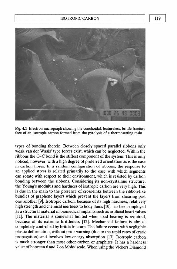
L-______________ I_SO_T_R_O_P_I_C_C_A_R_B_O_N ______________ ~I I 119
Fig. 4.1 Electron micrograph showing the conchoidal, featureless, brittle fracture face of an isotropic carbon formed from the pyrolysis of a thermosetting resin.
types of bonding therein. Between closely spaced parallel ribbons only weak van der Waals' type forces exist, which can be neglected. Within the ribbons the C-C bond is the stiffest component of the system. This is only noticed, however, with a high degree of preferred orientation as is the case in carbon fibres. In a random configuration of ribbons, the response to an applied stress is related primarily to the ease with which segments can rotate with respect to their environment, which is resisted by carbon bonding between the ribbons. Considering its non-crystalline structure, the Young's modulus and hardness of isotropic carbon are very high. This is due in the main to the presence of cross-links between the ribbon-like bundles of graphene layers which prevent the layers from shearing past one another [9]. Isotropic carbon, because of its high hardness, relatively high strength and chemical inertness to body fluids [10], has been employed as a structural material in biomedical implants such as artificial heart valves [11]. The material is somewhat limited when load bearing is required, because of its extreme brittleness [12]. Mechanical failure is almost completely controlled by brittle fracture. The failure occurs with negligible plastic deformation, without prior warning (due to the rapid rates of crack propagation) and involves low-energy absorption [13]. Isotropic carbon is much stronger than most other carbon or graphites. It has a hardness value of between 6 and 7 on Mohs' scale. When using the Vickers Diamond

120 I I~ ______ THE ___ R_M __ O_SE_TT __ IN_G __ RE __ S_IN __ M_A_T_R_IX __ P_R_E_CU_R_S_O_R_S ______ ~ Indentation equipment, the indentation disappears almost as soon as the load is removed, suggesting that the material retains some of its elastic properties after heat treatment [14].
The hardness and high strength of the material suggest the structure includes a degree of tetrahedral (Sp3) cross-links between the hexagonal layers. This is considered likely in view of the presence of such cross-links in the starting material and the isotropy of properties irrespective of the method of fabrication of the polymer precursor. The inter-ribbon crosslinks are strained and so are less thermally stable than the trigonal (Sp2) bonds within the graphene layers. They are thus progressively ruptured at high temperatures and thought to be responsible for viscoelastic behaviour observed at around 2500 ·C [8].
4.3 CARBON YIELD FROM POLYMERS
The number of thermoset polymer impregnants that could be used to process carbon-carbon composites is almost limitless. When all the process and property requirements are considered, the selection is reduced to relatively few materials. In the selection of the matrix precursor the following characteristics must be considered:
1. viscosity; 2. cure conditions; 3. carbon yield; 4. shrinkage during carbonization; 5. matrix microstructure.
It is necessary to achieve good impregnation of the preform structure, controlled cure of the resin and bonding of the fibre/matrix interface.
One of the most important prerequisites for an efficient carbon-carbon process is a matrix precursor with a high carbon yield. The carbon yield of a polymer can be found by heating a known weight of the polymer in an inert atmosphere at a given temperature, and weighing the carbon residue. The carbon yield is given simply by the ratio of the weight of the carbon residue to the initial weight and is expressed as a percentage figure. The conversion efficiency of the resin is defined as the ratio of the weight of carbon residue to the amount of carbon in the original resin.
Many long-chain polymers break down completely into gaseous products. Madorsky [15] showed that polyethylene at one extreme and PTFE at the other leave no carbon residue whatsoever. Polyvinyl fluoride (CH2CHF)n and polytrifluoroethylene (CHFCF2)n also leave very little residue. By contrast (CF2CH2)n has a carbon yield of 30% which accounts for all of the carbon originally present in the polymer, i.e. a conversion efficiency of 100%. Mackay [16] determined the carbon yield for a whole range of

L-__________ C_A_RB __ O_N_TI_E_L_D __ FR_O_M __ P_O_L_YME ___ R_S __________ ~I I 121
Table 4.1 Carbon yields of various thermoset precursors
Precursor
Phenolic resins Furan resins Oxidized polystyrene Polyvinyl alcohol Polyacrylonitrile Polyvinylidene chloride Cellulose Epoxy resins Polystyrene Polymethylmethacrylate
Carbon yield (% )
50-55 50-60 55 50 44 25 20 5 5 5
polymers (Table 4.1) and came to the conclusion that the carbon yield of a polymer cannot be predicted. Linear polymers such as polystyrene or poly-p-xylene, despite a high degree of aromacity, produce low carbon yields. Linear polymers of furan resins and polyphenylene oxide, in which ring structures are interspersed with ether linkages, provide high carbon yields. The conversion efficiency for furan resins, for example, is 91 % .
Carbon yield does not seem to be influenced by whether the polymer is thermoplastic or thermosetting, linear or cross-linked, but rather by whether it is capable of cyclization, ring fusion or chain coalescence at the onset of carbonization. In general, the resins should have a high degree of aromacity, or similar ring structures, and high molecular weight. There should be no more than one carbon atom between aromatic rings otherwise chain scissions will take place leading to volatilization of fragmental parts, as witnessed in the low yield from poly-p-xylene. Nitrogen, if present, should be in the ring structure and not in the chain. For example, polybenzimidazole is more stable and provides higher carbon yields than amine-cured epoxy resins. Other elements such as sulphur do not affect the stability of the polymers but do result in lower carbon yields and low conversion efficiency. All phenolic resins, except those in which the para-position is blocked by either phenyl or methyl groups, are good carbon-forming materials.
Very few resins have carbon yields of over 40% on pyrolysis, thus the choice of matrix precursor is severely limited. Many types of thermosetting resin have been studied for potential use as matrix precursors for carbon-carbon composites. Carbon yield and X-ray diffraction data on several resins that exhibit high carbon yields are given in Table 4.2 along with some of their chemical formulae/structures in Fig. 4.2. Even though the chemical structures of these resins are quite different, they all produce an isotropic, 'glassy' carbon residue as shown by X-ray diffraction data. Data on graphite are included for comparison.

122 I I~ ______ TH __ E_R_M_O __ SE_TT __ IN __ G_R_E_S_IN_M __ A_T_R_IX __ PRE __ C_U_R_S_O_R_S ______ ~ Table 4.2 Characteristics of carbonized high-yield thermoset resins
Carbon X-ray diffraction yield at data after HTT of 800 'c 2700 'c
Resin precursor (%) Lc (A) La (A)
Furan 50-60 75 3.41 Phenolics 50-60 132 3.40 Polyirnide 60 75 3.44 Polybenzimidazole 73 40 3.45 Polyphenylene 85 54 3.44 Biphenol resins 65 83 3.43 *Natural graphite 100 3.36
Polyvinylchloride [
H CI l \/
,/c;C,,- J H H n
Polyvinylidenechloride
Cellulose
Phenolic resin
OH

L-__________ C_A_R_B_O_N __ y_IE_L_D_F_R_O_M __ P_O_L_y_M_E_R_S __________ ~I I 123
Furfuryl alcohol
Polyacrylonitrile
Kapton (Polyimide)
Polyphenylene
C III
C I
It C
III C
I It
'5-\ (l \\\ (l
C==C-H
Fig. 4.2 Chemical structure of a number of thermoset resin carbon matrix precursors.

THERMOSETIING RESIN MATRIX PRECURSORS 124 I I L-__________________________________________________ ~
4.4 CARBONIZATION OF POLYMERS
Along with a high carbon yield and ease of impregnation of the fibres, there are three further requirements for a suitable matrix precursor. Firstly, the carbonization shrinkage of the matrix should not damage the carbon fibre skeleton. Secondly, the porosity formed during pyrolysis of the resin must be open and accessible to further impregnation. Only under such preconditions can further improvement of density and mechanical properties be achieved by subsequent processing cycles. Finally, the thermoset precursor will not have a Tg much below the onset of decomposition/ carbonization, otherwise the material will carbonize in a rubbery state and the pyrolysis gases will explode the porosity. Phenolic resins, for example, have a Tg greater than the onset of carbonization temperature (due to the high primary covalent and secondary N bond cross-link density) and are thus ideal.
In principle, the resin impregnation process consists of forming a near net shape component of carbon fibre reinforced, high carbon yield, resin by standard composite technologies. The component is cured and postcured according to the instructions of the resin supplier, followed by carbonization in an inert atmosphere to around 1000 .c. Optimization of the curing and post-curing stages is of great significance since they have a profound effect upon the carbon yield of the polymer and the mechanical properties of the carbon produced [13]. Efficient curing allows the polymerization of the resin to tend towards completion, thus reducing the number of low molecular weight compounds that would be liable to evaporate during pyrolysis and lower the carbon yield. Post-curing induces three-dimensional cross-linking in the resin which is carried over into the structure of the isotropic carbon. Cross-linking further reduces carbon loss during pyrolysis and, by restricting the movement of graphene fibrils under loading, improves the mechanical properties. Furthermore, post-curing causes the water by a condensation mechanism produced during polymerization which (but not fully desorbed) to come out of the cured structure. If the water is left in, there will be very high pore pressures in the laminate as it is carbonized. When the temperature exceeds 100 ·C the vapour pressure of the water in the laminate will exceed the ambient pressure used in carbonization and will eventually exceed the interlaminar strength of the component and cause processing delaminations. There is, however, an optimum degree of cross-linking for each resin system. If the amount of cross-linking becomes too great, large thermal stresses can build up during carbonization which lead to premature failure. The shrinkage of the resin during curing and carbonization produces slit-shaped pores which require to be refilled by liquid matrix precursor for subsequent recarbonization if the density and mechanical properties of the porous carboncarbon skeleton are to be improved.

CARBONIZATION OF POLYMERS I I 125 L-__________________________________________________ ~
Pore mouth
Resin impregnation
Cured resin Carbonized resin
Fig. 4.3 Schematic mechanisms of pore filing and blockage during the resin densification of carbon-carbon composites [17].
Figure 4.3 shows a schematic diagram of the mechanisms of pore filling and pore blockage by liquid re-impregnation. The chemical vapour deposition (CVD) technique may also be employed [17]. In the liquid densification method, the component is generally vacuum impregnated with a resin or pitch and then recarbonized. The resin may be the same as that used in the initial lamination, a different resin, a combination of resins or a combination of resin and pitch. To aid penetration into the bulk of the sample, the resins are often diluted with a solvent to lower the viscosity; the solvent must be evaporated prior to curing and carbonization. Figure 4.4 shows how the density of the composite increases rapidly with the first two or three reimpregnation cycles but then, reaches a plateau such that there is little to be gained from carrying out more than five cycles. The redensification process approximately follows a '112 power law'. The reason for this is that some of the surface pores become blocked after the first few cycles, thus reducing the efficiency of subsequent treatements. Despite the fact that liquid reimpregnants are often considerably 'thinned down' using solvents, it is considerably difficult to densify areas in the centre of thick components as a result of the blocking effect of the densified outer plies of the laminate. This problem is analogous in many ways to that of surface crusting hindering the densification of thick artefacts by CVD (Chapter 3). The inability of the mUltiple impregnation cycles to fill/heal the porosity and shrinkage cracks formed in a composite during carbonization results in a relatively large number of cracks and voids present in the microstructure of 'fully dense' composites (Fig. 4.5).
The suitability of carbon matrices for further impregnation has been

126 I ~I ______ TH __ E_R_M_O_S_E_TT __ IN_G_R_E_S_I_N_M_A_T_R_IX __ PR_E_C_U_R_S_O_R_S ______ ~
1.9
1.8 7' E 1 .7 u .9 1.6 ~ 'w 1.5 c: ~ 1.4
=§ 1.3 co
1.2
2 3 4 5 6 7 8 Number of carbonization cycles
Fig. 4.4 Effect of reimpregnationirecarbonization cycles on the density of carboncarbon composites fabricated by the thermoset resin route.
Fig. 4.5 Polarized optical micrograph of carbon-carbon composite made from carbon/phenolic precursor, reimpregnated five times with a pitch/furan blend. Note the lined but open shrinkage cracks and pores, illustrating the inefficiency of the reimpregnation technique in the interior of thick samples.

k-___________ C_A_RB __ O_N_IZ_A_T_I_O_N_O_F_P_O_L_YM __ E_R_S __________ ~I I 127
Fig. 4.6 Phenolic 'Novolac' chemical structure.
studied in detail by Fitzer and Gkogkdis [18]. The resins fall into two distinct groups with quite different pyrolysis behaviour. Resins such as polyimides and polyphenylene achieve high carbon yields in excess of 75% and produce high-strength composites after only one cycle of impregnation and carbonization. This results from the high yield and low isotropic shrinkage without damage to the fibre. Unfortunately, the mechanical properties achieved after the first carbonization cannot be enhanced by further densification cycles because the carbon formed consists mainly of closed pore systems [19,20]. The second group of resin precursors, represented by phenolics and furans, form porous carbon matrices. The composites possess poor mechanical properties after the first carbonization as a result of the inefficient stress transfer from matrix to fibres. Large improvements in mechanical properties can be achieved by repeated impregnation and carbonization cycles. For example, the flexure strength, measured in three-point bending, can be more than doubled after five cycles.
The problem with the majority of thermosetting resins is that they are not available in a form suitable for effective impregnation of porous preforms. Furthermore, many of the high carbon yield resins form an isotropic carbon with closed rather than open porosity, so that further densification and consequent improvement of composite mechanical properties are not possible. Use of high-yield resins will reduce the number of densification cycles required to achieve desired density. A high resin precursor raw-material cost may be borne since reducing the number of recarbonization cycles significantly lowers the processing costs. Unfortunately, many of the high-yield systems investigated to date have involved polymers whose prices approach those of precious metals and their use cannot therefore be justified! A brief review of high carbon yield resin systems is given in Section 4.8. The problems of processability, formation of closed porosity and cost have meant that only two resin systems, phenolics and furans, have been commercially exploited to any significant extent in carbon-carbon processing. In general, phenolic resins are used for the

128 I IL-___ TH_E_RM_O_S_E_TI_I_N_G_RE_S_IN_MA_T_R_IX_PRE_C_U_R_S_O_R_S __ ------.J
initial impregnation /carbonization cycle, while furan resins and resin/pitch mixtures are used for further densification.
4.4.1 Phenolic resins
Phenolic resins are a group of polymers in which the chain consists of a phenolic group interspersed with, for example, a methylene bridge. They are formed in a condensation polymerization between, for example, phenol and formaldehyde. The presence of excess formaldehyde produces methylene cross-links between the chains, again by a condensation mechanism. Phenolic resins may be produced by two methods, one of which is a single-stage process, the other involving two stages.
In the single-stage process phenol is reacted with an excess of formaldehyde so that the phenol : formaldehyde (P : F) ratio is less than 1. The mixture is heated with an alkaline catalyst, such as sodium hydroxide or ammonia. The polymerization is halted at an early stage so that the resin is converted to the A- or B-stage. The A-stage resin, known as a Resol, is a short chain, low molecular weight, linear polymer which is completely soluble in the alkaline solution. The B-stage resin, or Resitol, is a relatively long linear polymer with a slight degree of cross-linking between the chains. The compound is insoluble in alkaline solution, but readily soluble in organic solvents. When cooled, the B-stage resin becomes hard and brittle but on heating resoftens. A- and B-stage resins are used as adhesives, castings, plastics and as matrices in composites. Prolonged heating to higher temperatures results in extensive cross-linking and the formation of the C-stage resin, a hard and rigid infusible and insoluble product [21].
The two-stage process begins with a mixture in which the P : F ratio is greater than 1. The material is heated in the presence of an acid catalyst resulting in a linear chain condensation product (referred to as Novolac [22] which contains methylene linkages almost quantitively [23,24]. In the structure, ortho- and para-links occur at random as shown in Fig. 4.6. The Novolac, like Resitol, is fusible and soluble in organic solvents. It is generally ground to a powder and mixed with hexamine (NiCH2)6) which acts as a cross-linking agent via methylene linkages thus converting the Novolac to a hard infusible solid [25].
The response of a phenolic resin to heat treatment depends on the degree of cross-linking. When a weakly cross-linked material is heated slowly, low molecular weight compounds, such as unreacted phenol, shortchain polymers and water are evolved between 100 and 350 .c. Above 500 ·C small quantities of carbon monoxide and methane are evolved. If the material is highly cross-linked water is not evolved until above 400 ·C and the amount of low molecular weight polymer volatilized is considerably reduced. It is difficult to follow the detailed rearrangements of the chemical

L-______ C_A_R_B_O_N_I_Z_A_T_IO_N_O_F_P_O_L_y_M_E_R_S ______ ----'I 1 129
;e o
OJ 0'1
60
jl 40 c i Vl
OJ E 20 :J
~
o 500 1000 1500 2000 2500 Heat treatment temperature("c)
Fig. 4.7 Volume contraction of phenolic resins during pyrolysis.
structure of the resin during carbonization. A number of hypothetical interpretations of the complex reactions which take place, often simultaneously, are available [26-28] however. Fitzer et al. [29] suggest that between 100 and 300 ·C polymerization proceeds, forming long-chain, crosslinked polymers. Above 300 ·C oxygen is liberated in the form of water and carbon monoxide or carbon dioxide. At around 500 ·C the structure has rearranged into a highly unsaturated aromatic residue capable of forming a cross-linked aromatic network. The carbonization of pheonolic resin may be followed qualitatively by observing contraction with respect to temperature. A typical curve (Fig. 4.7) of volume contraction versus time exhibits three features: around 40% contraction below 500 ·C due to the removal of water, abrupt contraction of approximately 10% between 600 and 700 ·C and a steady contraction at higher temperatures as a result of dehydrogenation.
4.4.2 Furan resins
Furan resins are made from furan,
~C_C/H II II
H-C C-C-H \ / II
o 0
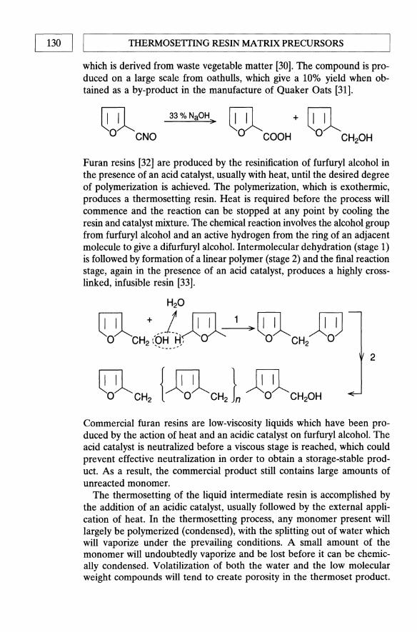
130 I IL-___ THE __ R_M_O_S_E_TI_IN_G_RE_S_IN_MA_T_RI_X_PR_E_C_U_R_S_O_R_S __ -----'
which is derived from waste vegetable matter [30]. The compound is produced on a large scale from oathulls, which give a 10% yield when obtained as a by-product in the manufacture of Quaker Oats [31].
~ 33% NaOH ..
o CNO
Furan resins [32] are produced by the resinification of furfuryl alcohol in the presence of an acid catalyst, usually with heat, until the desired degree of polymerization is achieved. The polymerization, which is exothermic, produces a thermosetting resin. Heat is required before the process will commence and the reaction can be stopped at any point by cooling the resin and catalyst mixture. The chemical reaction involves the alcohol group from furfuryl alcohol and an active hydrogen from the ring of an adjacent molecule to give a difurfuryl alcohol. Intermolecular dehydration (stage 1) is followed by formation of a linear polymer (stage 2) and the final reaction stage, again in the presence of an acid catalyst, produces a highly crosslinked, infusible resin [33].
H20
~ + __ .!. rill 1 .. ~ JeD o CH2 (PH M,0c1" 0 CH2 0 ..... __ .....
2
Commercial furan resins are low-viscosity liquids which have been produced by the action of heat and an acidic catalyst on furfuryl alcohol. The acid catalyst is neutralized before a viscous stage is reached, which could prevent effective neutralization in order to obtain a storage-stable product. As a result, the commercial product still contains large amounts of unreacted monomer.
The thermosetting of the liquid intermediate resin is accomplished by the addition of an acidic catalyst, usually followed by the external application of heat. In the thermosetting process, any monomer present will largely be polymerized (condensed), with the splitting out of water which will vaporize under the prevailing conditions. A small amount of the monomer will undoubtedly vaporize and be lost before it can be chemically condensed. Volatilization of both the water and the low molecular weight compounds will tend to create porosity in the thermoset product.
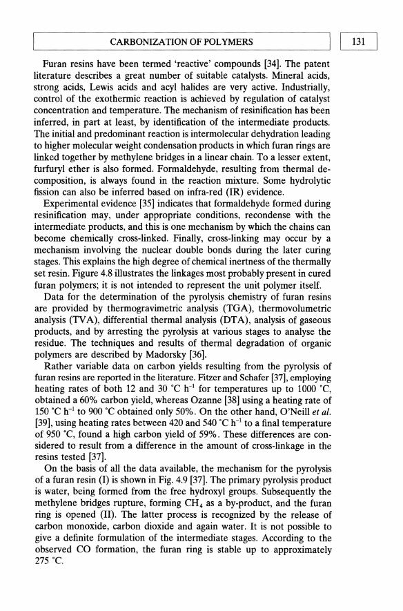
L-__________ C_A_RB __ O_N_I_Z_A_TI_O_N_O_F_P_O_L_YM __ E_R_S __________ ~I I 131
Furan resins have been termed 'reactive' compounds [34]. The patent literature describes a great number of suitable catalysts. Mineral acids, strong acids, Lewis acids and acyl halides are very active. Industrially, control of the exothermic reaction is achieved by regulation of catalyst concentration and temperature. The mechanism of resinification has been inferred, in part at least, by identification of the intermediate products. The initial and predominant reaction is intermolecular dehydration leading to higher molecular weight condensation products in which furan rings are linked together by methylene bridges in a linear chain. To a lesser extent, furfuryl ether is also formed. Formaldehyde, resulting from thermal decomposition, is always found in the reaction mixture. Some hydrolytic fission can also be inferred based on infra-red (IR) evidence.
Experimental evidence [35] indicates that formaldehyde formed during resinification may, under appropriate conditions, recondense with the intermediate products, and this is one mechanism by which the chains can become chemically cross-linked. Finally, cross-linking may occur by a mechanism involving the nuclear double bonds during the later curing stages. This explains the high degree of chemical inertness of the thermally set resin. Figure 4.8 illustrates the linkages most probably present in cured furan polymers; it is not intended to represent the unit polymer itself.
Data for the determination of the pyrolysis chemistry of furan resins are provided by thermogravimetric analysis (TGA), thermovolumetric analysis (TV A), differential thermal analysis (DTA), analysis of gaseous products, and by arresting the pyrolysis at various stages to analyse the residue. The techniques and results of thermal degradation of organic polymers are described by Madorsky [36].
Rather variable data on carbon yields resulting from the pyrolysis of furan resins are reported in the literature. Fitzer and Schafer [37], employing heating rates of both 12 and 30 ·C h-1 for temperatures up to 1000 ·C, obtained a 60% carbon yield, whereas Ozanne [38] using a heating rate of 150 ·C h-1 to 900·C obtained only 50%. On the other hand, O'Neill et al. [39], using heating rates between 420 and 540 "C h-1 to a final temperature of 950 ·C, found a high carbon yield of 59%. These differences are considered to result from a difference in the amount of cross-linkage in the resins tested [37].
On the basis of all the data available, the mechanism for the pyrolysis of a furan resin (I) is shown in Fig. 4.9 [37]. The primary pyrolysis product is water, being formed from the free hydroxyl groups. Subsequently the methylene bridges rupture, forming CH4 as a by-product, and the furan ring is opened (II). The latter process is recognized by the release of carbon monoxide, carbon dioxide and again water. It is not possible to give a definite formulation of the intermediate stages. According to the observed CO formation, the furan ring is stable up to approximately 275·C.

132 I I ~------------------------------------------------~
THERMOSETTING RESIN MATRIX PRECURSORS
1/0\ 1°\ -C C --CH -C C -CH 2--
I II 2 1/ II HC-CH C- CH
I I yH2
HC-CH C--CH HC--CH
/0\ 1 Il II I' II II HC C,,- CH2- C\ /C -CH2 - C\ /C-CHZO-{;HiC \ I CH
'I 0 ° ° C-CH
I CH 2
I o I
CH2 I C--CH HC--CH H2C --CH 2 HC--HC
II II I II I I II II HC C- CH -C C -CH -C C -CH -C C-CH-\ 1 2 1\ / 2 II II 2 "\ / 2
o ° 0 0 0
Fig. 4.8 Cross-linking in furan rJsins.
Between 300 and 400 ·C the IR band for the C-O-C bond of the furan ring, at a wavelength of 5.85 11m, loses its intensity, due to the rupture of the furan ring. In the gas analysis, this temperature is characterized by a maximum in the first carbon monoxide formation as well as by release of water. A quantitative calculation reveals that, taking into account the hydroxyl group decomposition to water, half the furan ring oxygen must be released as water. The other half is liberated as carbon monoxide.
At 400 ·C, new IR bands begin to appear which indicate the beginning of a build-up of aromatic systems. These aromatic systems are formed spontaneously from the fragments of the furan rings. They have also been identified by Braun [40] using Diamond's X-ray profile analysis.
At temperatures above 450 ·C a reaction of pyrolysis water with remaining methylene bridges occurs, (III) in Fig. 4.9. This secondary reaction to form alkanone groups is readily recognized from the decrease in the formation of water above 450 .c. In the same temperature range, the formation of methane ceases because of the oxidation of the methylene bridges and significant amounts of hydrogen are released. Above 460 ·C

CH
4
CO
c0
2L
H
H20
1
30
1-
19
01
24
51
-12
75
-
370
46
49
0
100
~(lJ"g(
H,ijlC
HfOH
o 0
oj n
20
0
300
400
I CH
I
CH
I
-H2
0 -C
HI,
8(J"
~ ~~c' i
!~c~
-C0
2-C
O
I II
I II
II <4
500C
-C
~/C-
-CyC
--t~
/C-
.II
I I
I n
>45
0°C
-t H
20
l-H
2
t e
t ~
C
//\/\//\/\//\
500
-C
C
C
C
C
~-
I 1\
I II
I II
l=ffio
-C
C--
C
C--c
C-
460
C
~/
~/
~/
c c
C
I I
I n
III
Fig
. 4.
9 T
he p
yrol
ysis
che
mis
try
of
fura
n re
sins
[36
].
600
I I
I I
C
C
C
c /;'\/~/~/~
-C'
c C
C
t-
I II
I I
I -C
C
C
C
c
~/\/;\I;\I/
C
c C
C
I
I I
I
.DL
n
§ ~ ~ .... ~ ~ i ~

cn-4J ,---I ___ TH_E_R_M_O_S_E_TII_N_G_RE_S_IN_M_A_T_R_IX_PRE_C_U_R_S_O_R_S __ -----'
the carbon groups liberate carbon monoxide, leading to a highly unsaturated aromatic C-H residue (IV) capable of forming cross-linked aromatic systems.
During pyrolysis polyfurfuryl alcohol exhibits around 20% linear shrinkage [37]. This shrinkage corresponds to the known behaviour observed during the production of commercial isotropic carbon products [41].
The density of the carbon produced is around 1.55 g cm-3• When comparing this bulk density with that of graphite (2.267 g cm-3 ) a difference of 30% appears which is attributed to the different structural arrangement.
It has also been shown [37] that a variation in the degree of cross-linking in the starting materials will affect the consecutive chemical steps of the decomposition and the formation of gaseous by-products. A decrease in the amount of cross-linking will diminish the carbon yield in the residue by promoting the formation of low molecular weight compounds.
4.5 CARBONIZATION OF COMPOSITES
In a composite laminate or structure, the matrix acts as a medium for the effective transfer of load on to the reinforcing fibres. The properties of the matrix and the fibre/matrix interface thus make important contributions to the mechanical properties of the composite. Failure in polymer composites will most likely initiate at the fibre/matrix interface so that bonding in this region is of prime concern. Strong fibre/matrix adhesion is generally achieved by some form of surface treatment of the fibres [42,43]. The matrix in carbon-carbon composites is very brittle in nature. The microstructure of the carbon matrix will therefore play a major role in the initiation of failure, whereas fibre/matrix bonding is responsible for the transmission of cracks. Pyrolysis of the polymer composites strongly influences both the microstructure of the carbon matrix and the nature and strength of the fibre/matrix interface [44,45].
The shrinkage of the resin matrix as a result of carbonization is observed to be the most critical factor governing the mechanical properties of the carbon-carbon product. The surface properties of the carbon fibres have been demonstrated to control the pyrolysis shripkage and subsequent microcrack density in the carbon matrix [44]. It is the formation of such cracks which results in composites of low strength. Bradshaw and Vidoz correlated the strength of different carbon-carbon composites to the strain to failure of the matrix [46], which they believed to be controlled by the differential shrinkage between fibre and matrix and the consequential crack formation. The difference in fracture behaviour of carbonized polymers has been attributed to differences in fibre matrix bonding both before and after pyrolysis [47]. Manocha [48] observed the changes occurring during

L-__________ C_A_RB __ O_N_IZ_A_T_IO_N __ O_F_C_O_MP __ O_S_IT_E_S __________ ~I I 135
the carbonization of polymer composites using dilatometer measurements of shrinkage in tandem with microstructural observations [49].
The dimensional changes observed during the pyrolysis of a carbon fibre reinforced polymer occur as a direct result of thermal degradation and shrinkage of the polymer matrix [44,45]. In a unidirectionally reinforced composite the changes in the fibre axis direction are controlled by the longitudinal thermal expansions of the carbon fibres, which are very small. As a result, there is very little measurable dimensional change in that direction. In the direction perpendicular to the fibres, however, appreciable changes are observed. Very little bulk dimensional change is observed in woven or multi-directional fibre-reinforced composites because of the fibres. The matrix on the other hand shrinks significantly, resulting in the production of a system of cracks.
Figure 4.10 shows the general trends in the dimensional changes (change in thickness of unidirectional (UD) composites) observed in an unreinforced polymer (furan resin) and the same material reinforced with non-surfacetreated (relatively weak fibre/matrix bonding) and surface-treated (strong interface) carbon fibres on pyrolysis. Each of the materials undergoes a reversible thermal expansion up to around 200 .c. Further heat treatment results in the onset of shrinkage in the range 300-450 .c. Shrinkage begins at around 300 ·C for the unreinforced polymer, reaching a maximum between 350 and 700 .c. In the composites, the onset of shrinkage is suppressed by 50-100 .c. The fibre reinforcement is found to influence both the onset of shrinkage as well as the rate. In composites made with surface-treated carbon fibres shrinkage starts at 350 ·C, while in those made with non-surface-treated fibres it begins at around 420 .c. The maximum shrinkage in both composite systems occurs between 450 and 650 ·C. Between 650 and 800 ·C the rate of shrinkage is reduced to about half that measured between 450 and 650 .c. Shrinkage continues up to about 1100 ·C but is very slow above 800 .c.
Microscopical observations show the fibres to be well bonded to the matrix. At around 500 ·C gaps begin to appear between the fibres and matrix in composites with non-surface-treated fibres. Composites with surface-treated fibres display a mixed type of microstructure with microcracks formed in the bulk matrix as well as at the fibre matrix interface. As the HTT is increased towards 1000 "C, the interface debonding increases in the non-surface-treated fibre composites, while in those composites using surface-treated fibres the interface appears to become progressively stronger.
The shrinkage of the matrix on pyrolysis is due to the degradation of the polymer chains in the 300-600 ·C range and coalescence of the C-C chains in the 600-800 "C temperature range [21]. In the case of composites using non-surface-treated fibres, the fibre/matrix interface is of the weak 'mechanical'type [44,45], much weaker than the C-C bonding within the

136 I L-I ___ THE __ RM_O_S_E_TII_N_G_RE_S_I_N_MA_T_RIX __ P_RE_CU_R_S_O_R_S ___ ---'
~ III III QJ C
I,
3
2
-4
-6
-8
~ -10 £ ,£ QJ -12
i u
-14
-16
-18
o 200
\ \ \
\ \
\ \ \ \
\ \ \ \
\ \ \ \
\ '" , ~
unremforcod '" surface treat~d fibres .... non-treated fibres _____
I J 400 600 800 1000
Temperature I'e I
Fig. 4.10 Dimensional changes in composites during pyrolysis [45].
isotropic carbon matrix. When carbonized the matrix shrinks away from the fibres with little displacement of the fibres. The result is a gap between matrix and fibres and a low bulk shrinkage. By contrast, the bond between surface treated fibres and matrix is of the strong 'chemical' variety [44,45]. The strong interface developed in the polymer system is carried over into the carbonized structure with the result that the matrix does not shrink away from the fibre. During pyrolysis, the fibres become displaced by the shrinkage of the matrix. The consequence is a large bulk shrinkage of the composite and a large degree of matrix cracking.
The extent of the chemical bond between fibres and matrix will vary with the type and degree of surface treatment, be it oxidation to produce

GRAPHITIZATION I I 137 L-________________________________________________ ~
reactive groups or sizing with some form of coupling agent. The strength of the interface may therefore be tailored to suit the required properties. Mechanical testing shows there to be an optimum fibre/matrix bond strength when developing carbon-carbon composites with good mechanical properties. Too strong an interface produces brittle composites exhibiting catastrophic failure and poor strength, as matrix cracks pass straight through any fibre they intersect absorbing very little work of fracture. If the bond strength is too low, composites will tend to fail in shear with poor translation of fibre strength. Treating the fibres so that an intermediate bond strength is achieved will result in a mixed mode fracture and a resulting higher strength.
4.6 GRAPHITIZATION
In carbon-carbon composites with a matrix derived from a thermosetting resin, the microstructure is very much dependent on the HIT. When an unreinforced thermosetting resin is pyrolysed it will form an isotropic carbon [13]. No evidence of a graphite-like structure is apparent from X-ray analysis. When the resin is heat treated in the composite form with carbon fibres present, a graphitic anistropy can be detected by density measurements, X-ray diffraction and optical microscopy (Fig. 4.11) [49]. With furan resins this phenomenon is very marked and anisotropic regions begin to develop in the matrix at temperatures as low as 1000 .c. Above 2200 ·C these anisotropic regions gradually adopt a graphite crystal structure, such that at 2800 ·C the matrix is essentially all graphite.
The observations cannot be explained on the basis of the known structures and properties of the respective components. It is believed, therefore, that there must be some interfacial effect occurring between the carbon fibres and the isotropic carbon matrix during heat treatment [50]. During carbonization the resin shrinks by up to 50% by volume, while the fibres change very little in dimension. It has been postulated that the driving force for the graphitization of the 'non-graphitizing' matrix is the stress accumulation caused by the difference in the coefficients of thermal expansion between the matrix and fibres. Kamiya and Inagaki [51] reported the existence of such a stress accumulation when heat treating natural graphite/isotropic carbon composites. They estimate these stresses to be of the order of 300 MN m-2•
An abrupt graphitization of isotropic carbon has been observed at pressures above 3 kbar [52,53]. Glassy or isotropic carbon has also been reported to graphitize at high temperatures by the addition of the natural graphite powder [29,54]. On the basis of the evidence observed to date, it would appear that the graphitization of isotropic carbons at high temperatures is a direct result of the accumulation or application of stress. For this reason the phenomenon is referred to as stress graphitization [55].

138 I IL--___ TH_E_R_M_O_S_E_IT_I_N_G_RE_S_IN_MA_T_R_IX_PR_E_C_U_R_S_O_R_S __ -------1
Fig. 4.11 Evidence of graphitization of the isotropic carbon matrix in polymerderived carbon-carbon systems after heat treatment to 2500 ·C as shown by polarized light microscopy.
It has been suggested, using optical microscopy techniques, that the graphite microstructure above an RTf of 2200 ·C is orientated in such a way that the graphite planes in the matrix surround the fibre . The graphite layers are divided into a number of domains and, as a whole, are observed to envelope the fibres [56]. The temperature for the manifestation of such a graphitic microstructure varies according to the fibre type; the higher the modulus of the fibre the lower this temperature will be. Based on their observations, many workers suggest that the graphitization of the matrix begins at the fibre/matrix interface and progresses with time and temperature into the bulk. One must, however, question the validity of the microscopical evidence presented in this case. Optical anisotropy observations from polarized light microscopy are used to explain the detailed molecular reorientation occurring in regions often only 1 or 2 J..lm in size between 7 J..lm diameter fibres. It is the opinion of the author that a certain degree of 'artistic (or scientific!) licence' has been employed such that microscopical observations beyond the limit of their ire solution are being used to support what appears to be the most likely explanation. The development of a graphitic structure in the matrix of carbon-carbon composites is crucial to the understanding of their mechanical properties. While the hypothesis that graphitization beings at the fibre/matrix interface and
IMPREGNATION TECHNOLOGY I I 139 L-________________________________________________ ~
progresses into the 'bulk' appears the most plausible, it cannot be conclusively proved without the use of higher resolution techniques.
Recently, studies on the origins of graphitization in resin-derived isotropic carbon matrices have been carried out using high-resolution TEM and selected area X-ray diffraction (SAD) techniques [57]. The material investigated was produced from high-modulus mesophase pitch-based fibres (Thomel P 75) and a polyaromatic thermoplastic resin (PEEK) matrix (Chapter 5). Graphitic domains were observed to form at a relatively low temperature in this system (1600 0C). A sympathetic alignment of the graphene structure in the matrix with that in the fibre was evident but this could not be linked to crystal nucleation at the fibre surface. Stress graphitization was believed to be responsible for the observation made but, as yet, it has not been possible to obtain detailed knowledge of the mechanism for the observed phenomena.
Carbon-carbon composites made by the thermoset polymer route are very often given a 'graphitization' treatment to temperatures up to 2500 dc. This results in a higher density, improved ablation resistance and the 'opening up' of porosity to aid reimpregnation cycles. The mechanism of the process and the microstructures obtained are, at present, not fully understood. The production of composite artefacts thus often occurs without a full understanding of the structural and physical changes which occur during manufacture.
4.7 IMPREGNATION TECHNOLOGY
Carbon-carbon composites formed by the thermoset resin technique are made by pyrolysing a laminated structure in an inert atmosphere to around 1000 dc. The resulting carbon fibre reinforced isotropic carbon matrix composites may be subsequently heat treated to higher temperatures of approximately 2500 °C in order to graphitize the matrix. The process is extremely inefficient, with up to half of the matrix being lost during carbonization, requiring several steps to produce the final artefact. It is, however, considerably quicker and cheaper than CVD processing, and the equipment required, in what is an ambient pressure fabrication route, is not limited by size or the requirement of a large initial capital investment. Furthermore, high-quality precursors, often exhibiting extremely complex geometries, may be produced by exploiting the technology developed for the 'conventional' composites industry.
4.7.1 Hand lay-up
The simplest method of making a composite is to lay the fibres on to a mould by hand, paint on the resin, build up the required number of layers
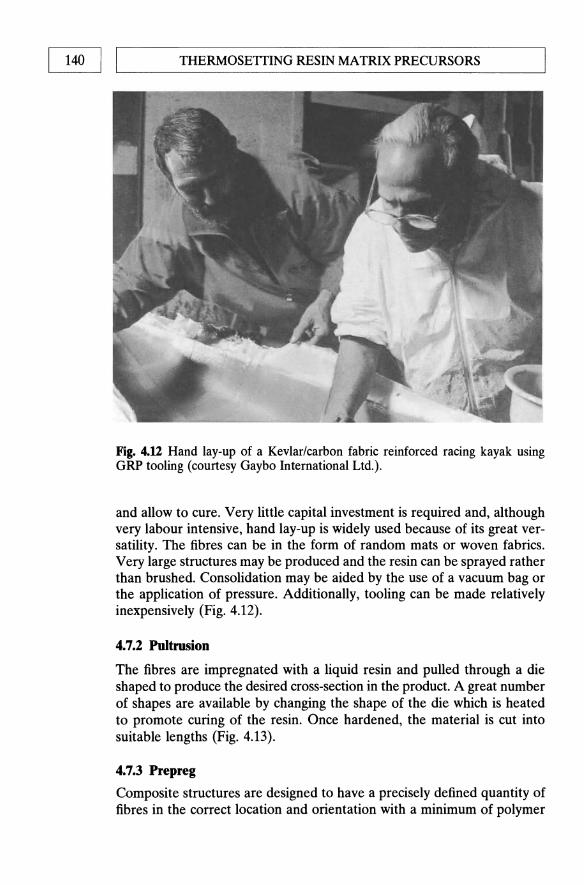
THERMOSEITING RESIN MATRIX PRECURSORS 140 I I ~--------------------------------------------------~
Fig. 4.U Hand lay-up of a Kevlar/carbon fabric reinforced racing kayak using GRP tooling (courtesy Gaybo International Ltd.).
and allow to cure. Very little capital investment is required and, although very labour intensive, hand lay-up is widely used because of its great versatility. The fibres can be in the form of random mats or woven fabrics. Very large structures may be produced and the resin can be sprayed rather than brushed. Consolidation may be aided by the use of a vacuum bag or the application of pressure. Additionally, tooling can be made relatively inexpensively (Fig. 4.12).
4.7.2 Pultrusion
The fibres are impregnated with a liquid resin and pulled through a die shaped to produce the desired cross-section in the product. A great number of shapes are available by changing the shape of the die which is heated to promote curing of the resin. Once hardened, the material is cut into suitable lengths (Fig. 4.13).
4.7.3 Prepreg
Composite structures are designed to have a precisely defined quantity of fibres in the correct location and orientation with a minimum of polymer

L-___________ I_M_P_R_E_G_N_A_T_IO_N_TE __ C_HN __ O_L_O_G_y ____________ ~I I 141
Continuous fibre spool or fabric roll
Fig. 4.13 Continuous pultrusion process.
to provide the support. The composites industry achieves this precision using prepreg as an intermediate product. Prepreg is a broad tape of aligned or woven fibres, impregnated with polymer resin. A laminated plaque or component is fabricated by stacking successive layers of prepreg followed by some form of curing cycle. Prepregs designed as carbon-carbon precursors are generally produced with a higher resin content to account for weight loss on carbonization.
Fibres are converted into a prepreg either by bringing a number of spooled tows into a collimated tape (Fig. 4.14) or by impregnating a woven fabric. The fibre contructions may be impregnated using either a hot-melt or solvent-coating process. The hot-melt operation consists of heating a matrix resin to obtain a low viscosity to produce a well-dispersed fibreresin mass. The volume fraction of fibre is controlled by the number of tows brought into the web or by the construction of the weave. The resin is cast on to the substrate paper either on the prepreg line or in a separate filming operation in order to obtain the desired fibre : resin ratio. The prepreg is calendered to obtain a uniform thickness and to close fibre gaps before being wound on a core. Substrate paper is generally left between layers of tape. The paper is coated with a release film.
Solvent coating is achieved by immersing the fibre web or fabric into a bath containing 20-50% of a solvent/resin mixture followed by some form of drying process (Fig. 4.14).
Resin content is controlled either by the use of metering rolls after impregnation or by adjustment of solvent: resin ratio. The drying process reduces volatiles and advances the resin molecular weight.
The finished product from either route is a thin sheet of fibre-reinforced resin which is generally wound on a cardboard core and interleaved with release paper. Table 4.3 shows typical ranges of production dimensions.
A general rule of thumb is that unidirectional prepregs tend to be made by the hot-melt process, whereas fabrics are usually impregnated by
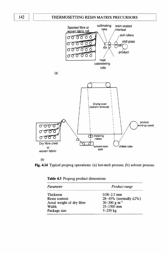
142 1 ,---I ___ T_H_E_R_M_O_SE_TT_I_N_G_RE_S_IN_M_A_T_R_IX_PRE_C_U_R_S_O_R_S ___ _
(a)
Dry fibre creel or
woven fabric
(b)
heat calendering
rolls
: Drying oven \ (solvent removal)
I I I I
metering rollers
solvent-resin bath
resin-coated interleaf
chilled roller
product wind-up spool
Fig. 4.14 Typical prepreg operations: (a) hot-melt process; (b) solvent process.
Table 4.3 Prepreg product dimensions
Parameter
Thickness Resin content Areal weight of dry fibre Width Package size
Product range
0.08-2.5 mm 28-45% (normally ±2%) 30-300 g m-2
25-1500 mm 5-250 kg

L-___________ I~ __ RE __ G_N_A_T_I_O_N_TE __ CHN __ O __ LO_G_Y ____________ ~I I 143
0
250 o UD tope 4fu • Balanced fabric ~
~ 200 3~ c 9 CIi
150 L-
VI 2Ui ~ ::J 100 ~
"8 1 ~ ~ 50 ~
Fig. 4.15 Comparison of mechanical properties between tape and fabric prepregs.
the solvent route. Thermoplastic resin prep regs (Chapter 5) tend to be manufactured by a combination of puitrusion and solvent impregnation.
Carbon reinforcing fibres are, by their nature, extremely anisotropic. Consequently, unidirectional prepreg tapes reinforce primarily in the O· direction (fibre axis). Tapes offer the best translation of fibre properties because the fibres are not crimped or distorted as in fabric prepregs. Significant differences in mechanical properties exist between tape and fabric. Figure 4.15 shows typical tensile property differences between tape and fabric prepregs. The differences arise due to the fabrics having a significant proportion of fibres perpendicular to the applied load and as a result of fibre crimping. The weave pattern of a fabric controls the handling characteristics and, to a degree, influences the mechanical properties of a product which uses it as reinforcement. The plain weave, interlacing one warp yam over and under one fill yam, exhibits the greatest degree of stability with respect to yam slippage and fabric distortion (Fig. 4.16). The eight-harness satin weave has one warp yam interlacing over seven and under one fill yam in an irregular pattern. The result is a pliable fabric which readily conforms to compound contours. A fabric in this form will possess improved mechanical properties over a plain weave, as a consequence of these being fewer fibre distortions at cross-overpoints. Furthermore, since the movement of fibres is less restricted, an eight-harness satin weave will conform more readily to the shape of a mould, but at the expense of reduced energy absorption and fabric stability. This is because the greater the number of cross-over points, the greater will be the energy transference to adjoining fibres. A number of fabric forms exist, each attempting to exploit a different compromise of stability, conformity and energy absorption, etc. (Fig. 4.17).
The measure of the adhesion of the prepreg to the surface of tooling or other prepreg sheets is known as tack. The level of tack is carefully

144 1 ,---I ___ TH_E_R_M_O_SE_TT_I_N_G_R_E_S_IN_M_A_T_R_IX_PR_E_C_U_R_S_O_R_S ___ -----'
WARP THREAD (END) , II il n fl ~ n n
--'~ p i I
I I I I
9 I
=:J I !
0 I I
tJ I i
9 I
P I
d l_ U '---' U ,- U '-- LJ FILL THREAD (PICK)
2345678
t::\ _1::\ ~ f:::\'(91~ FILL END
:~~yW~~~r (a) WARP END
controlled in order to optimize lay-up operations and, as such, may vary considerably from process to process. It is affected by the apparent viscosity of the resin. Tack may be increased by increasing resin and volatile contents, by retarding polymerization or by increasing lay-up room temperature or humidity. Resin formulations may thus be reapportioned or additives blended in in order to control tack. Thermoplastic prepregs, by nature of their being prepolymerized, do not possess tack, adding difficulty to processing. Successive layers may, however, be spot welded together to alleviate this problem. Ideally the tack qualities should be adequate to allow the prepreg to adhere to the prepared tooling surface or preceding plies of a laminate, but light enough to part from the backing film without loss of resin.
Flow is the measure of the amount of resin squeezed from a specimen as it cures (under heat and pressure) between press platens. Flow measurement indicates the capability of the resin to fuse successive plies in a laminate and to bleed out volatiles and reaction gases. Flow can be an indicator of prepreg age or advancement of polymerization. It is often desirable to optimize resin content and viscosity to attain adequate flows.

L-___________ I_M_P_R_E_G_N_A_T_IO_N __ TE_C_HN __ O_L_O_G __ y __________ ~1 I 145
WARP END
2345678
I f-.. ----- FLOAT -------t ___ ,
~ r FILL PICK WARP END
(b) FIBRE CRIMPS
Fig. 4.16 Fabric construction forms showing degree of fibre crimp, of (a) plain weave, (b) eight-harness satin weave.
Prepreg flow may also be controlled by adding thickening or thixotropic agents to the resin. The length of time a specimen remains between heated platens until the resin gels, or reaches a very high viscosity, is known as the gel time of the prepreg [58]. Gel time measurements may be used to estimate the degree of advancement and 'shelf life' of the material. Most prepregs are formulated to attain a useful life of 10 days or more under standard laboratory conditions. Cold storage is often used to lengthen shelf life. The formability of a material around contours is denoted drape and is critical to fabrication costs. Tapes are typically less drapable than fabric forms of prepreg. It is paramount that prepregs be staged to desirable tack and drape qualities.

(a)
(b)
(c)
--
----
'--'
l.-.
J '--J~U'-'~U
LJIJ
Wlj
LJU
LJ
(d)
(e)
(f)
Fig
. 4.
17 W
oven
fab
ric
cons
truc
tion
s: (
a) p
lain
wea
ve;
(b)
bask
et w
eave
; (c
) tw
ill
wea
ve;
(d)
four
-har
ness
sat
in w
eave
; (e
) ei
ght-
harn
ess
sati
n w
eave
; (f
) fi
ve-h
arne
ss s
atin
wea
ve.
o ~ m
~ 0 c;n m d 18 fil c;
n .....
Z ~ > g ><
'"I;j fil 8 ~ c;n 0 ~
c;n
I
'---______ I_M_P_R_E_G_N_A_TI_O_N_TE_C_HN_O_L_O_G_y ______ -----'1 I 147
Historically, prepregs have been laid up by hand with an operator cutting lengths of material and laying them in a mould prior to autoclave cure (Chapter 7). As previously stated, unidirectional tapes are extremely anisotropic with properties maximized in the fibre direction. The mechanical response of a unidirectional laminate is characterized by high strength and modulus parallel to the fibres and poor transverse properties; 0°/90° laminates are produced to improve transverse properties (at the expense of axial) while balanced 0°/90° ± 45° laminates approach isotropic in plane strength asymptotically with increasing thickness - for this reason they are referred to as quasi-isotropic (Fig. 4.18). The laminator cuts lengths of tape and places them on the mould surface in the desired ply orientation. The process uses one of the cheaper forms of prepreg and requires low initial capital investments in both equipment and facilities. Unfortunately, this method results in a high wastage of material, fabrication time, manpower costs and operator-to-operator variability. Indeed the scrap factor in such an operation may exceed 50% depending on complexity and size of components. Lay-up times may be reduced by using templates to aid the cutting process and a number of companies are in the process of developing computer numerically controlled (CNC) tape-laying machines.
Woven fabric prepregs can be made to conform to the complex geometries of low-stressed artefacts by a process known as darting. The technique involves slitting the prepregs at locations where folds would normally occur in a lay-up. The excess material is removed and the edges butted together. Alternatively, the prepreg may be slit at points where a crease would normally form and the excess material allowed to overlap. When the former method is employed an additional ply may be required to compensate for the weak butt joints in the laminate. In the case of highly stressed constructions the fabric prepregs should be cut in predetermined patterns so that joints in successive plies do not coincide. When fabric reinforcements are laid up on complex double curvature shapes, the weave patterns become distorted and the fibre directions changed. As a result ply alignments in heavily draped lay-ups are difficult to control. Offaxis angle ply fabrics of, for example ±60° ±45°, are used to compensate for undetermined deficiencies.
The high shrinkage occurring during carbonization and the brittle nature of the isotropic carbon matrix have dictated that commercially exploited carbon-carbon composites formed by the thermoset route are generally produced from woven prepregs. Laboratory specimens, on the other hand, are often produced in unidirectional forms to facilitate easier analysis by the reduction of experimental variables.
Once laid up, the composite structures require to be cured under temperature and pressure prior to carbonization. This is carried out by compression moulding in a heated press, or by use of an autoclave (Chapter 7).

0 a 0
0
90
90
a· 00
a· a·
0
+45 ·
90
0 · ·
· a
-45
a ·
· -4
5 ·
a a ·
· ·
90
+45
a· a·
a · a·"
, 7
90·..0/~~/~
90
·CC
CC
C//
C//
/
L/ L~7 L
·/
UN
IDIR
EC
TIO
NA
L 0/
90·
QU
AS
I-IS
OTR
OP
IC
Fig
. 4.1
8 T
he m
ost
com
mon
ly u
sed
lay-
ups
of
UD
pre
preg
s.
~ ~ ~ o en ~ o § en Z ~ ~ 8 ~ o ::0
en

IMPREGNATION TECHNOLOGY I I 149 L-__________________________________________________ ~
single or multiple continuous fibre spools
Fig. 4.19 Filament-winding process.
4.7.4 Filament winding
The filament-winding technique allows the high speed, precise lay-down of continuous fibre reinforcement in predescribed patterns. Resin-impregnated fibre tows are wound over a rotating male mandrel (Fig. 4.19). In the wet winding process the fibres are solution impregnated just prior to being wound on the mandrel. The dry winding method, on the other hand, uses single-tow prepreg as its feedstock. Two types of winding machine exist; rotating mandrel and stationary mandrel. There are, in addition, two methods of winding available: polar (or planar) in which each layer of fibres is wound without spaces or cross-overs, and helical winding, in which both spaces and cross-overs occur. In both cases the fibres are laid on to the mandrel in a helical pattern with the helix angle being chosen to suit the application. The construction of the mandrel requires considerable skill. It must not collapse under the pressure resulting from the fibrewinding tension and must be easily removed once the process is complete. Segmented metal forms (usually steel faced with plaster) are most commonly used.
The mandrel may be cylindrical, spherical or any shape that does not exhibit re-entrant curvature. Filament-winding operations have the capacity to vary the winding tension, wind angle or resin content in each layer of reinforcement until the desired thickness and resin content of the composite are achieved along with the required direction of strength. The great advantage of the process is that the cost is generally lower than the prepreg cost for most materials [59]. The lower costs arise because a relatively expensive fibre can be combined with an inexpensive resin to produce a relatively inexpensive composite. Coupled with this is a high-speed laydown of fibre. Table 4.4 illustrates the major advantages and disadvantages of filament winding.
The fabrication of the composite winding is completed by the curing operation. The structure can be cured easily in an oven without the need of pressure. Recently certain manufacturers have used vacuum bags and