chapter 9 gasoil conversion - أ.د. طارق البحري - conversion.pdf649 675 734 6–(-14) -...
TRANSCRIPT
Petroleum Refining – Chapter 9: Conversion
9-1
Chapter 9 GASOIL CONVERSION
Introduction
• Processes that convert gasoil to lighter products are
1. Hydrocracker
2. FCC
• Significant change in the IBP and FBP
1. The Fluid Catalytic Cracking (FCC)
Introduction
• Location → Only in MAA.
• Designer → UOP.
• Capacity → 40,000 BPSD.
• Objective → To convert gas oil to lighter and more valuable products like; LPG,
gasoline, distillate, and cycle-oil.
• FCC is a high temperature low pressure catalytic unit in which heavy hydrocarbons
are cracked into lighter molecules.
• Originally cracking was accomplished thermally.
• The catalytic cracking of gasoil has replaced thermal cracking because (through
catalyst design) it gives
- Better yields.
- Better selectivity
• Catalytic Cracking processes
1. Thermafor Catalytic Cracker (TCC)
– Moving bed reactor.
– Not very common
2. Fluid Catalytic Cracker (FCC)
– Fluidized bed reactor.
– More common.
• The basic operation of the two is similar.
Feeds and Products
• FCC Feed is a mix of the following refinery streams:
1. VGO from MAA.
2. VGO from MAB.
3. CGO from MAB.
4. Hydrocracker fractionator bottoms.
Table 9-1. Hydrocracker feedstock properties.
API, gravity
S, wt%
N, ppm wt
Ni, ppm wt
Va, ppm wt
ASTM distillation, ºF, IBP
50%
FBP
24.5
0.6
1000
< 0.1
< 1
550
830
1050
Prof. Tareq A. Albahri 2018 Kuwait University Chemical Engineering
9-2
• FCC Product yields depend on mode of operation: (There are two modes)
1. Gasoline mode.
2. Distillate mode.
• Distillates are usually blended into diesel, jet fuel, and furnace/heating oil.
Table 9-2: FCC unit products, weight %.
Product Gasoline mode Distillate mode
Off gas (C3-)
LPG vapor
Light gasoline
Heavy gasoline
Distillate
Light cycle oil
Heavy cycle oil
Coke
4.29
17.88
35.54
14.76
13.05
0.83
7.32
4.8
Table 9-3: FEED 40,000BPD (VGO 75v%, CGO 26v%) FCC products yields
Product wt%
Off Gas 4.35
LPG 20.40
Light Gasoline 32.98
Heavy Gasoline 13.37
Distillate 15.94
LCO 0.64
HCO 7.70
Coke 4.62
TOTAL 100.0
Table 9-4: Typical product properties.
Treated light
gasoline
Treated heavy
gasoline
Distillate
Light
cycle oil
Heavy
cycle oil
API
Distillation, º F
IBP
50%
90%
FBP
70.6
95
158
248
302
33–43
280
340
387
410
16–26
399
500
662
734
10–13
621
649
675
734
6–(-14)
-
815
930
-
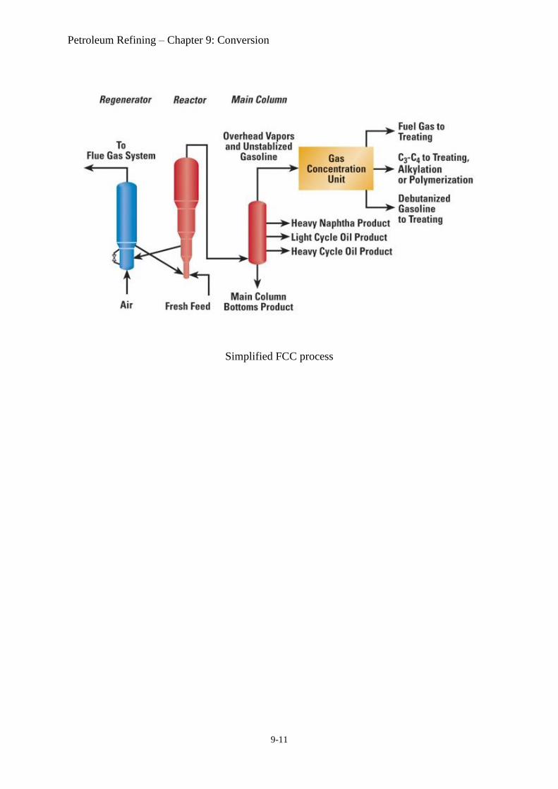
Process description (MAA refinery)
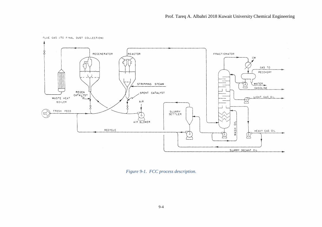
• The FCC unit consists of four main sections (Figure 9-8Figure 9-1):
1. Reactor/regenerator section.
2. Fractionator section
3. Gas concentration and recovery section.
4. Flue gas power recovery section.
1. Reactor/regenerator section
• The reactor in MAA FCC is an all-riser cracking reactor. Other designs have separate
reactor/riser sections.
Petroleum Refining – Chapter 9: Conversion
9-3
• The feed is preheated by a series of heat exchangers (recovering heat from within the
unit).
• It is then mixed with hot regenerated catalyst at the base of the riser.
• Heat from the catalyst further heats up and vaporizes the gasoil.
• The gasoil and catalyst travel up the riser (this is where the main cracking reactions
occur) into a region of low pressure.
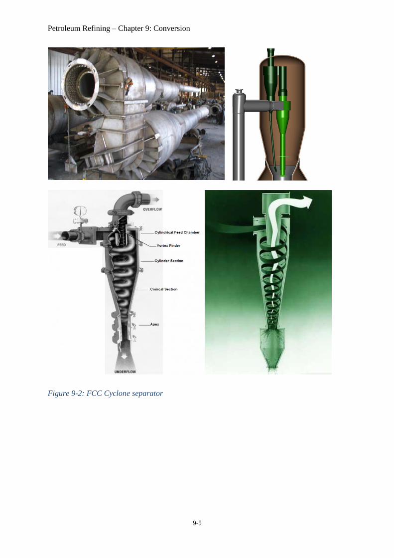
• The cracked hydrocarbons are separated from the catalyst (by a two-stage cyclone
system) and exit the reactor/riser top.
• The separated catalyst travel down the reactor riser into the reactor stripper section.
• In the reactor stripper section, stripping steam is used to separate the spent catalyst from
the hydrocarbon vapors.
• The spent catalyst travels down through a standpipe to the lower part of the regenerator
(combustor).
• In the regenerator, air is used to burn off the coke deposited on the catalyst particles.
• The regenerated catalyst and the flue gases travel up to the upper section of the
regenerator where they are separated by a two-stage cyclone system.
• The hot regenerated catalyst is mixed again with the feed at the bottom of the reactor.
• The flue gases are sent to the power recovery section where they are used to generate
steam or run a turbine.
2. Fractionator section
• The feed to the main fractionator is superheated vapors (this makes the heat removal a
major operation).
• Large quantities of light gases pass overhead with light gasoline. This is sent to the gas
concentration section.
• Heavy gasoline is withdrawn as a side cut.
• Heavy cycle oil is removed from the bottom of the column.
3. Gas concentration and recovery section.
• The feed to this section is the fractionator overhead product.
• This is separated using a stabilizer column to produce:
- Non-condensable gases (C1-C4).
- LPG (C3/C4).
- Stabilized light gasoline.
• The non-condensable gas is separated into two streams;
- Ethane and lighter (C2–).
- Propane and heavier (C3+).
• Two Merox units are provided to remove mercaptans1 from the following final products;
1. Light gasoline (from the stabilizer).
2. Heavy gasoline cut (from the main fractionator).
1 (Mercaptans are undesirable due to their acidity and offensive odor)
Prof. Tareq A. Albahri 2018 Kuwait University Chemical Engineering
9-4
Figure 9-1. FCC process description.
Petroleum Refining – Chapter 9: Conversion
9-5
Figure 9-2: FCC Cyclone separator

Prof. Tareq A. Albahri 2018 Kuwait University Chemical Engineering
9-6
Figure 9-3. FCC Reactor new installation
Figure 9-4. FCC reactor head internals
Petroleum Refining – Chapter 9: Conversion
9-7
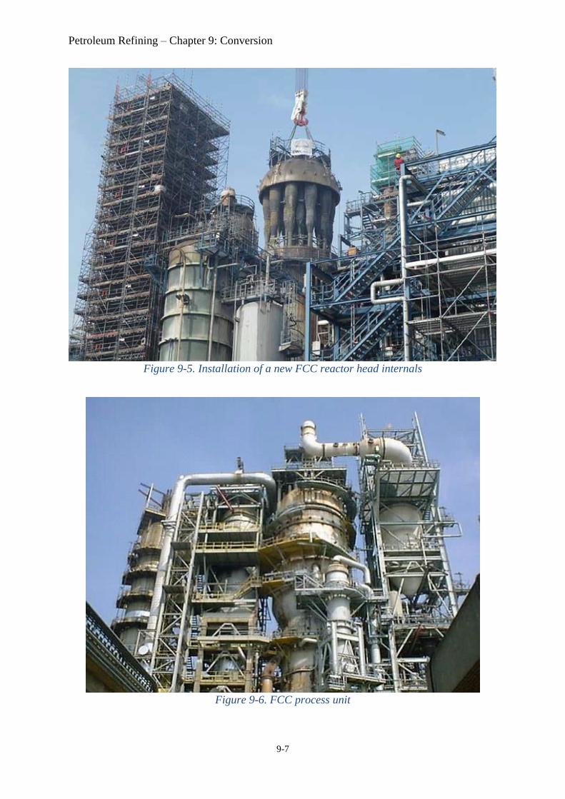
Figure 9-5. Installation of a new FCC reactor head internals
Figure 9-6. FCC process unit
Prof. Tareq A. Albahri 2018 Kuwait University Chemical Engineering
9-8
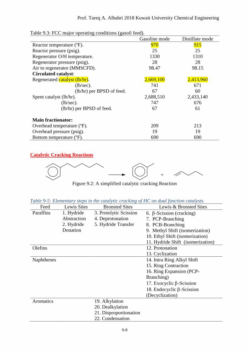
Table 9.3: FCC major operating conditions (gasoil feed).
Gasoline mode Distillate mode
Reactor temperature (ºF).
Reactor pressure (psig).
Regenerator O/H temperature.
Regenerator pressure (psig).
Air to regenerator (MMSCFD).
Circulated catalyst:
Regenerated catalyst (lb/hr).
(lb/sec).
(lb/hr) per BPSD of feed.
Spent catalyst (lb/hr).
(lb/sec).
(lb/hr) per BPSD of feed.
Main fractionator:
Overhead temperature (ºF).
Overhead pressure (psig).
Bottom temperature (ºF).
970
25
1330
28
98.47
2,669,100
741
67
2,688,510
747
67
209
19
690
915
25
1310
28
98.15
2,413,960
671
60
2,433,140
676
61
213
19
690
Catalytic Cracking Reactions
Figure 9.2: A simplified catalytic cracking Reaction
Table 9-5: Elementary steps in the catalytic cracking of HC on dual function catalysts.
Feed Lewis Sites Bronsted Sites Lewis & Bronsted Sites
Paraffins 1. Hydride
Abstraction
2. Hydride
Donation
3. Protolytic Scission
4. Deprotonation
5. Hydride Transfer
6. -Scission (cracking)
7. PCP-Branching
8. PCB-Branching
9. Methyl Shift (isomerization)
10. Ethyl Shift (isomerization)
11. Hydride Shift (isomerization)
Olefins 12. Protonation
13. Cyclization
Naphthenes 14. Intra Ring Alkyl Shift
15. Ring Contraction
16. Ring Expansion (PCP-
Branching)
17. Exocyclic -Scission
18. Endocyclic -Scission
(Decyclization)
Aromatics 19. Alkylation
20. Dealkylation
21. Disproportionation
22. Condensation
+
Petroleum Refining – Chapter 9: Conversion
9-9
FCC Catalysts
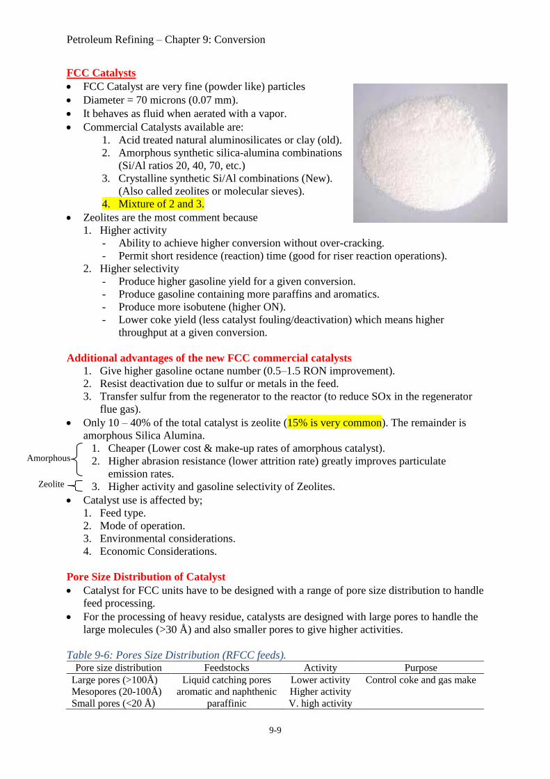
• FCC Catalyst are very fine (powder like) particles
• Diameter = 70 microns (0.07 mm).
• It behaves as fluid when aerated with a vapor.
• Commercial Catalysts available are:
1. Acid treated natural aluminosilicates or clay (old).
2. Amorphous synthetic silica-alumina combinations
(Si/Al ratios 20, 40, 70, etc.)
3. Crystalline synthetic Si/Al combinations (New).
(Also called zeolites or molecular sieves).
4. Mixture of 2 and 3.
• Zeolites are the most comment because
1. Higher activity
- Ability to achieve higher conversion without over-cracking.
- Permit short residence (reaction) time (good for riser reaction operations).
2. Higher selectivity
- Produce higher gasoline yield for a given conversion.
- Produce gasoline containing more paraffins and aromatics.
- Produce more isobutene (higher ON).
- Lower coke yield (less catalyst fouling/deactivation) which means higher
throughput at a given conversion.
Additional advantages of the new FCC commercial catalysts
1. Give higher gasoline octane number (0.5–1.5 RON improvement).
2. Resist deactivation due to sulfur or metals in the feed.
3. Transfer sulfur from the regenerator to the reactor (to reduce SOx in the regenerator
flue gas).
• Only 10 – 40% of the total catalyst is zeolite (15% is very common). The remainder is
amorphous Silica Alumina.
1. Cheaper (Lower cost & make-up rates of amorphous catalyst).
2. Higher abrasion resistance (lower attrition rate) greatly improves particulate
emission rates.
3. Higher activity and gasoline selectivity of Zeolites.
• Catalyst use is affected by;
1. Feed type.
2. Mode of operation.
3. Environmental considerations.
4. Economic Considerations.
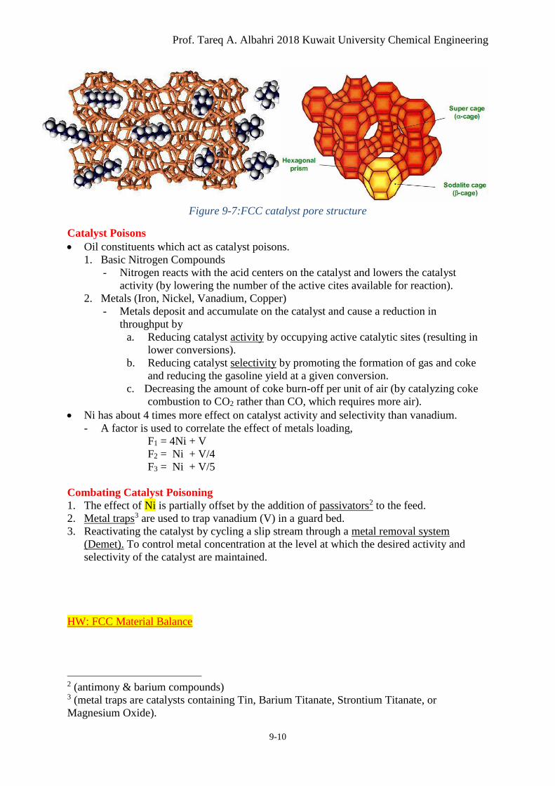
Pore Size Distribution of Catalyst
• Catalyst for FCC units have to be designed with a range of pore size distribution to handle
feed processing.
• For the processing of heavy residue, catalysts are designed with large pores to handle the
large molecules (>30 Å) and also smaller pores to give higher activities.
Table 9-6: Pores Size Distribution (RFCC feeds). Pore size distribution Feedstocks Activity Purpose
Large pores (>100Å) Liquid catching pores Lower activity Control coke and gas make
Mesopores (20-100Å) aromatic and naphthenic Higher activity
Small pores (<20 Å) paraffinic V. high activity
Amorphous
Zeolite
Prof. Tareq A. Albahri 2018 Kuwait University Chemical Engineering
9-10
Figure 9-7:FCC catalyst pore structure
Catalyst Poisons
• Oil constituents which act as catalyst poisons.
1. Basic Nitrogen Compounds
- Nitrogen reacts with the acid centers on the catalyst and lowers the catalyst
activity (by lowering the number of the active cites available for reaction).
2. Metals (Iron, Nickel, Vanadium, Copper)
- Metals deposit and accumulate on the catalyst and cause a reduction in
throughput by
a. Reducing catalyst activity by occupying active catalytic sites (resulting in
lower conversions).
b. Reducing catalyst selectivity by promoting the formation of gas and coke
and reducing the gasoline yield at a given conversion.
c. Decreasing the amount of coke burn-off per unit of air (by catalyzing coke
combustion to CO2 rather than CO, which requires more air).
• Ni has about 4 times more effect on catalyst activity and selectivity than vanadium.
- A factor is used to correlate the effect of metals loading,
F1 = 4Ni + V
F2 = Ni + V/4
F3 = Ni + V/5
Combating Catalyst Poisoning
1. The effect of Ni is partially offset by the addition of passivators2 to the feed.
2. Metal traps3 are used to trap vanadium (V) in a guard bed.
3. Reactivating the catalyst by cycling a slip stream through a metal removal system
(Demet). To control metal concentration at the level at which the desired activity and
selectivity of the catalyst are maintained.
HW: FCC Material Balance
2 (antimony & barium compounds) 3 (metal traps are catalysts containing Tin, Barium Titanate, Strontium Titanate, or
Magnesium Oxide).
Petroleum Refining – Chapter 9: Conversion
9-11
Simplified FCC process
Prof. Tareq A. Albahri 2018 Kuwait University Chemical Engineering
9-12
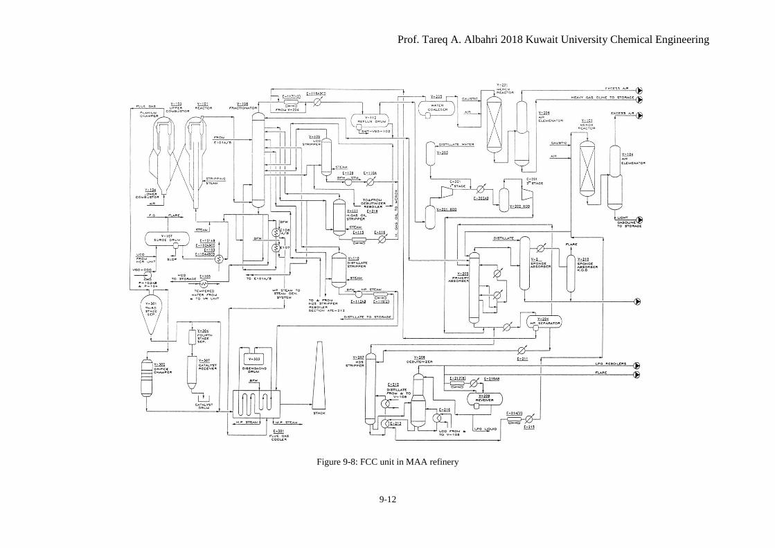
Figure 9-8: FCC unit in MAA refinery
Petroleum Refining – Chapter 9: Conversion
9-13
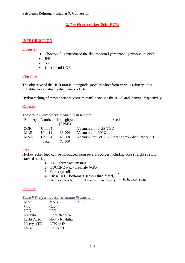
2. The Hydrocracker Unit (HCR)
INTRODUCTION
Licensors
• Chevron √ → introduced the first modern hydrocracking process in 1959.
• IFP.
• Shell.
• Unocal and UOP.
Objective
The objective of the HCR unit is to upgrade gasoil product from various refinery units
to lighter more valuable distillate products.
Hydrocracking of atmospheric & vacuum residue include the H-Oil and Isomax, respectively.
Capacity
Table 9-7: Hydrocracking capacity in Kuwait.
Refinery Number Throughput
(BPSD)
Feed
ZOR
MAB
MAA
Unit 84
Unit 14
Unit 84
38,000
40,000
Vacuum unit, light VGO
Vacuum unit, VGO
Vacuum unit, VGO & Eocene waxy distillate VGO.
Total 78,000
Feed
Hydrocracker feed can be introduced from several sources including both straight run and
cracked stocks,
1- VGO form vacuum unit
2- EOCENE waxy distillate VGO.
3- Coker gas oil.
4- Diesel HTU bottoms. (Heavier than diesel)
5- FCC cycle oils. (Heavier than diesel)
Products
Table 9-8: Hydrocracker Distillate Products.
MAA MAB ZOR
Gas
LPG
Naphtha
Light ATK
Heavy ATK
Diesel
Gas
LPG
Light Naphtha
Heavy Naphtha
ATK or IK
LP Diesel
In the gasoil range
Prof. Tareq A. Albahri 2018 Kuwait University Chemical Engineering
9-14
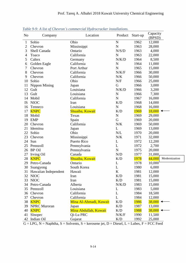
Table 9-9: A list of Chevron’s commercial Hydrocracker installations.
No Company Location Product Start-up Capacity
(BPSD)
1
2
3
4
5
6
7
8
9
10
11
12
13
14
IS
16
17
18
19
20
21
22
23
24
25
26
27
28
29
30
31
32
33
34
35
36
37
38
39
40
41
42
Sohio
Chevron
Shell Canada
Toaco
Caltex
Golden Eagle
Chevron
Chevron
Chevron
Sohio
Nippon Mining
Gult
Gult
Mobil
NIOC
Tenneco
KNPC
Mobil
EMP
Chevron
Idemitsu
Sohio
Chevron
Sun
Pennzoll
BP Oil
Irving Oil
KNPC
Petro-Canada
Ssangyong
Hawaiian Independent
NIOC
NIOC
Petro-Canada
Pennzoll
Chevron
Chevron
KNPC
NPRC Muroran
KNPC
Slnopec
Indian Oil
Ohio
Mississippi
Ontario
California
Germany
California
Port Arthur
California
California
Ohio
Japan
Louisiana
Louisiana
California
Iran
Louisiana
Shuaiba, Kuwait
Texas
Spain
California
Japan
Ohio
Mississippi
Puerto Rico
Pennsylvania
Pennsylvania
Canada
Shuaiba, Kuwait
Ontario
South Korea
Hawaii
Iran
Iran
Alberta
Louisiana
California
California
Mina Al-Ahmadi, Kuwait
Japan
Mina Abdullah, Kuwait
Qi-Lu PRC
Gujarat
N
N
N/S/D
N
N/K/D
N
N
N/K/F
N/K
N/F
G
N/K/D
N
N
K/D
N
K/D
N
G
N/K
L
N/L
N/K
L
L
N
N/D
K/D
L
L
K
K/D
K/D
N/K/D
L
L
L
K/D
K/D
K/D
N/K/F
K/D
1962
1963
1963
1963
1964
1964
1965
1966
1966
1966
1966
1966
1966
1967
1968
1968
1969
1969
1969
1969
1969
1970
1971
1972
1972
1975
1977
1978
1978
1980
1981
1981
1981
1983
1983
1984
1984
1986
1987
1988
1990
1992
12,000
28,000
4,000
22,000
8,500
11,000
15,000
30,000
50,000
25,000
3,000
3,200
7,300
16,000
14,000
16,000
18,000
29,000
20,000
50,000
13,000
20,000
32,000
12,200
2,700
20,000
31,000
44,000
10,000
6,000
12,000
15,000
15,000
15,000
5,000
18,500
12,000
38,000
13,000
38,000
11,500
25,000
G = LPG, N = Naphtha, S = Solvents, S = kerosene jet, D = Diesel, L = Lubes, F = FCC Feed
Modernization
Petroleum Refining – Chapter 9: Conversion
9-15
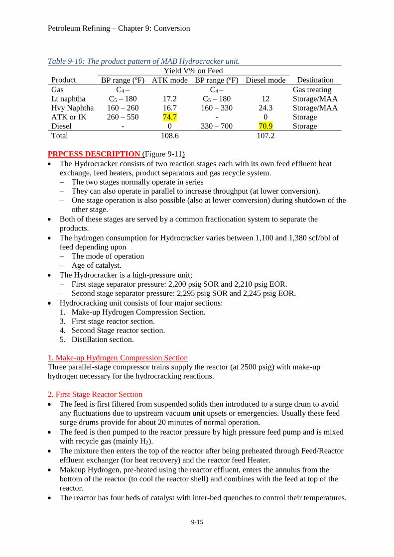
Table 9-10: The product pattern of MAB Hydrocracker unit.
Product
Yield V% on Feed
Destination BP range (ºF) ATK mode BP range (ºF) Diesel mode
Gas
Lt naphtha
Hvy Naphtha
ATK or IK
Diesel
C4 –
C5 – 180
160 – 260
260 – 550
-
17.2
16.7
74.7
0
C4 –
C5 – 180
160 – 330
-
330 – 700
12
24.3
0
70.9
Gas treating
Storage/MAA
Storage/MAA
Storage
Storage
Total 108.6 107.2
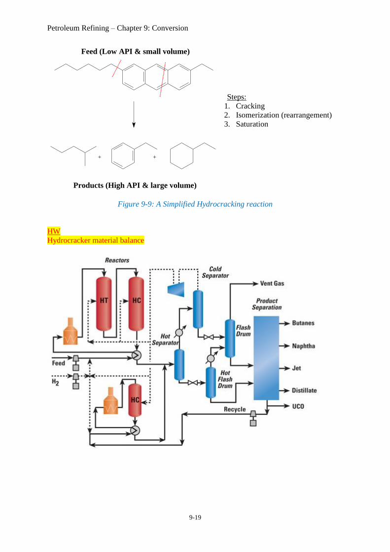
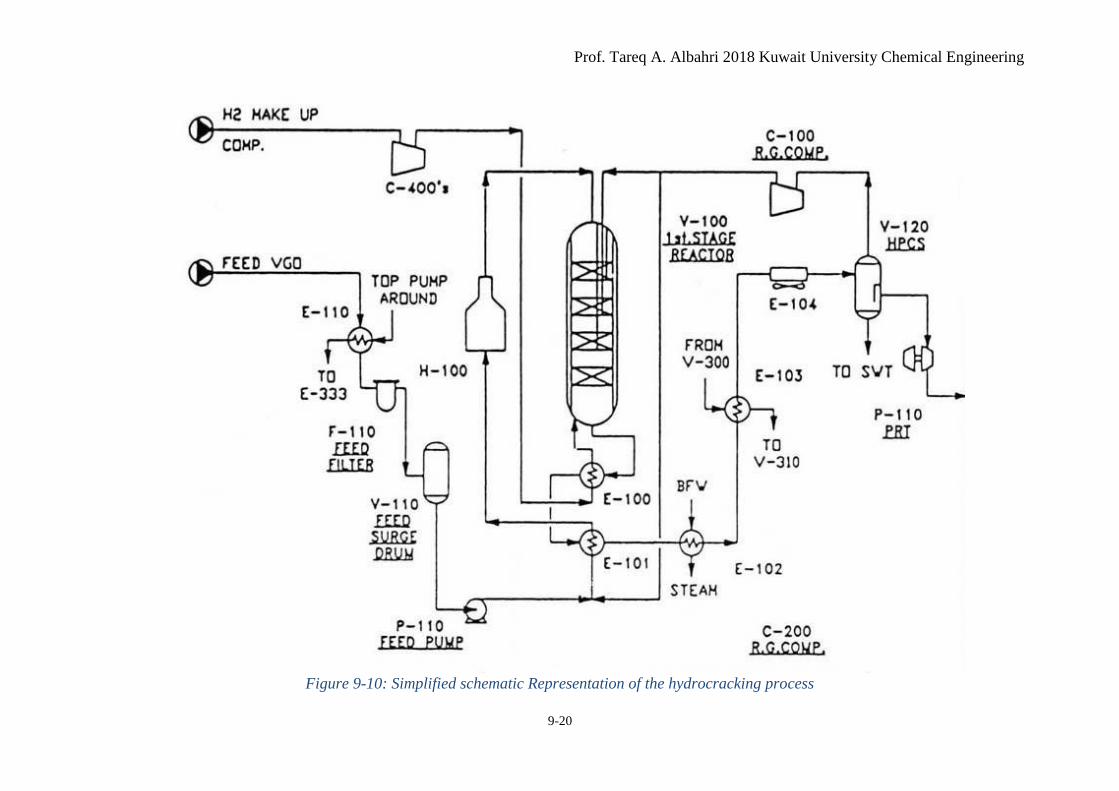
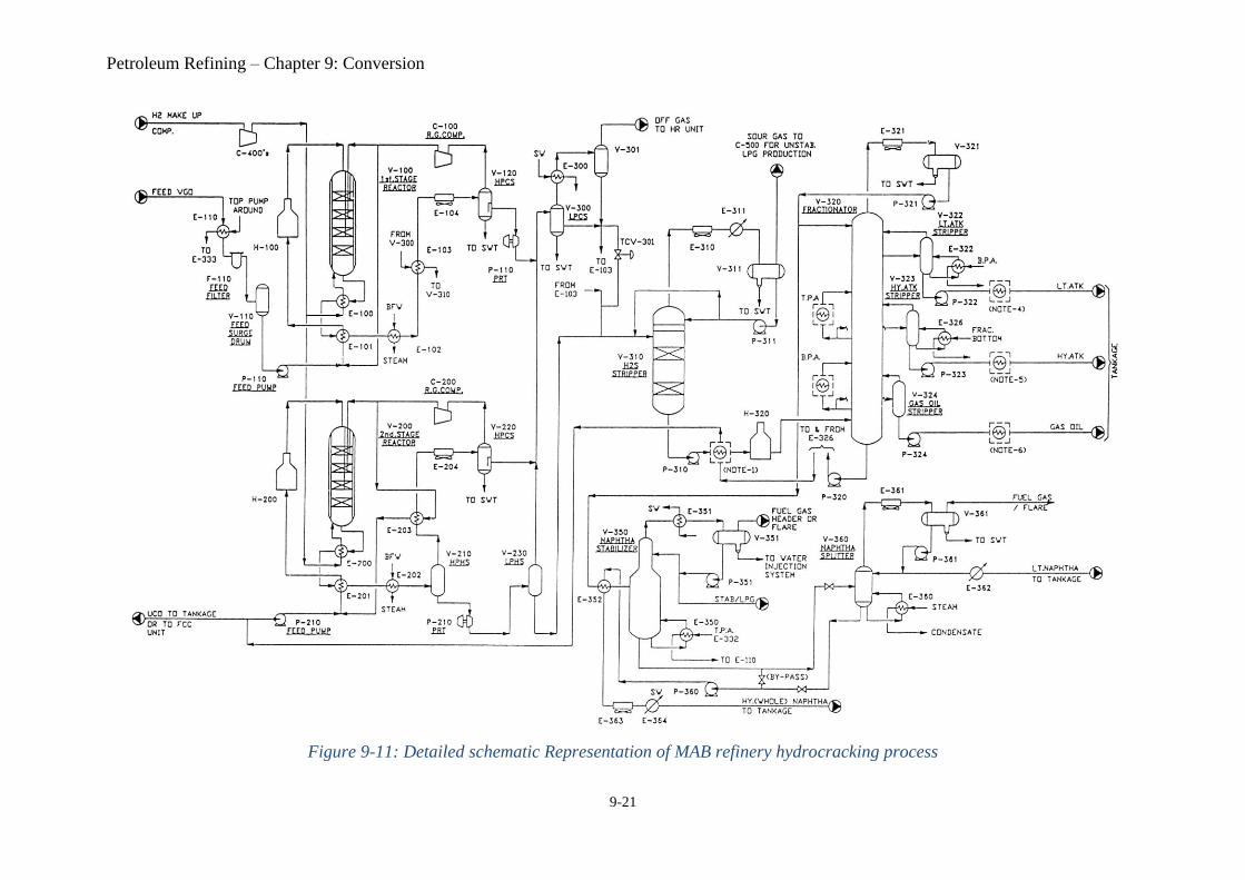
PRPCESS DESCRIPTION (Figure 9-11)
• The Hydrocracker consists of two reaction stages each with its own feed effluent heat
exchange, feed heaters, product separators and gas recycle system.
– The two stages normally operate in series
– They can also operate in parallel to increase throughput (at lower conversion).
– One stage operation is also possible (also at lower conversion) during shutdown of the
other stage.
• Both of these stages are served by a common fractionation system to separate the
products.
• The hydrogen consumption for Hydrocracker varies between 1,100 and 1,380 scf/bbl of
feed depending upon
– The mode of operation
– Age of catalyst.
• The Hydrocracker is a high-pressure unit;
– First stage separator pressure: 2,200 psig SOR and 2,210 psig EOR.
– Second stage separator pressure: 2,295 psig SOR and 2,245 psig EOR.
• Hydrocracking unit consists of four major sections:
1. Make-up Hydrogen Compression Section.
3. First stage reactor section.
4. Second Stage reactor section.
5. Distillation section.
1. Make-up Hydrogen Compression Section
Three parallel-stage compressor trains supply the reactor (at 2500 psig) with make-up
hydrogen necessary for the hydrocracking reactions.
2. First Stage Reactor Section
• The feed is first filtered from suspended solids then introduced to a surge drum to avoid
any fluctuations due to upstream vacuum unit upsets or emergencies. Usually these feed
surge drums provide for about 20 minutes of normal operation.
• The feed is then pumped to the reactor pressure by high pressure feed pump and is mixed
with recycle gas (mainly H2).
• The mixture then enters the top of the reactor after being preheated through Feed/Reactor
effluent exchanger (for heat recovery) and the reactor feed Heater.
• Makeup Hydrogen, pre-heated using the reactor effluent, enters the annulus from the
bottom of the reactor (to cool the reactor shell) and combines with the feed at top of the
reactor.
• The reactor has four beds of catalyst with inter-bed quenches to control their temperatures.
Prof. Tareq A. Albahri 2018 Kuwait University Chemical Engineering
9-16
• The reactor effluent is cooled by series of heat exchangers (heating other streams in the
unit for heat recovery) and coolers then enters a High Pressure Cold Separator (HPCS),
where water, gases and liquid hydrocarbons are separated.
• The gas stream from HPCS (mainly H2) is compressed by a recycle gas compressor and
recycled to the reactor feed and a portion is used for inter bed quenching.
• Being at high pressure, the hydrocarbon liquid stream from the HPCS is drawn on a level
control and drives a power recovery turbine (to provide power for the first stage feed
pump) before flowing to the Low Pressure Cold Separator (LPCS).
• LPCS gas is sent to Hydrogen Recovery (HR) unit through a K.O. drum while the liquid
stream enters the H2S stripper after heating with the reactor effluent.
• Superheated steam is introduced at the bottom of the stripper to remove H2S. The sour gas
from the stripper goes to the Amine treating unit (for further H2S concentration).
• The bottom stream from H2S stripper is heated through a series of heat exchangers and
fractionator feed heater before entering the Fractionator.
3. Second stage reactor section
• The second stage reactor section is similar to the first stage except for the following;
– The feed to second stage is the fractionator bottom.
– The reactor effluent undergoes both a hot and cold high-pressure separation.
• The reactor effluent is flashed in a high pressure hot separator (HPHS) before final
cooling.
• This cooled effluent is then separated into H2-rich recycle gas and oil in the high pressure
cold separator (HPCS).
• The gas is compressed and recycled to the second stage reactor as quench and recycle.
• Oil is drawn on level control and mixes with the oil products from the first stage and
feeds the low pressure cold separator (LPCS).
• The vapor from the HPHS is cooled by heating the recycle gas and then further cooled in
air coolers.
• The liquid from the HPHS drives the power recovery turbine to provide power for the
second stage feed pump and is then flashed again in the Low Pressure Hot Separator
(LPHS).
• Vapor from the LPHS is mixed with first stage liquid products and cold liquid products
from the HPCS. The combined stream is sent to the LPCS.
• Liquid from LPHS is sent as hot feed to the H2S stripper.
4. Distillation Section
4.1 Product Fractionation
• The fractionator operates like the crude unit fractionator to separate the converted
products from unconverted feed;
Overhead → naphtha.
Side-cut → light ATK, heavy ATK and gas oil.
Bottoms → unconverted feed.
• The fractionator bottoms (unconverted oil) is recycled to the second stage reactor section
for extinction.
• The fractionator has two pumparound circuits to improve/control column
fractionation/traffic and provide heat for reboilers and feed preheat.
• The fractionator overhead is totally condensed (using fin-fan coolers) so that no gas is
produced.
Petroleum Refining – Chapter 9: Conversion
9-17
• The condensed hydrocarbon (naphtha) and water (from steam) are separated in the reflux
drum.
- The water is sent to sour water unit (SWT) for treatment.
- The hydrocarbon liquid is split into two streams:
1. Overhead reflux which is returned to the column (Tray 50) to control
fractionator overhead temperature.
2. The naphtha product stream to the naphtha stabilizer then splitter.
• Light ATK is drawn from Tray 38 and is reboiled in the light ATK stripper to remove the
light ends and maintain the desired flash point and IBP.
• Heavy ATK is drawn along with the top pumparound at Tray 27 and is reboiled in the
heavy ATK side stripper using fractionator bottoms.
• All products are pumped to storage after cooling in a process, water, or fin-fan coolers.
4.2 Naphtha Stabilizer & Splitter
• The stabilizer removes butane and lighter material from the product naphtha to control
RVP and flash point.
• The stabilized naphtha (the stabilizer bottom) can then be
1. Sent directly to tankage as product (bypassing the splitter), or
2. Fed to the naphtha splitter and split into a light naphtha product (overhead)
and a heavy naphtha product (bottom).
• The products at the stabilizer overhead reflux drum are;
1. Gases: sent to the fuel gas system.
2. LPG: portion is used as reflux and the rest is sent to the hydrogen sulfide
recovery (HSR) unit.
• De-superheated steam reboils the splitter to hold a constant temperature on Tray 2 of the
column.
• Overhead, light naphtha is cooled (condensed) on temperature control then partially
refluxed back to the column to maintain the required ASTM gap specification between
light and heavy naphtha, and the rest is cooled then sent to storage.
• Heavy naphtha from the splitter bottoms is cooled then sent to storage.
FEATURES & APPLICATIONS
1. HCR Modes of operation
• The Hydrocracker has two modes of operation for which a particular liquid product yield
is maximized.
MAA Hydrocracker
1. ATK mode: where Aviation Turbine Kerosene yield is maximized. (This is the
primary mode of operation)
2. Mid-distillate mode: where ATK & diesel yield are maximized.
MAB Hydrocracker
1. ATK mode: maximum naphtha plus jet fuel (ATK) yield.
2. Diesel mode: maximum diesel yield.
2. The Complete conversion mode of operation
• The majority of the commercial hydrocrackers operate in a severe extinction recycle
mode to convert 100% of the feed to light products.
Prof. Tareq A. Albahri 2018 Kuwait University Chemical Engineering
9-18
• Chevron hydrocracking technology has been applied commercially in the full range of
process flow schemes
– Single-stage, once-through liquid.
– Single-stage, partial recycle of heavy oil
– Single-stage, extinction recycle of oil (100% conversion)
– Two-stage, once-through liquid.
– Two-stage, partial recycle of heavy oil
– Two-stage, extinction recycle of oil (100% conversion) ← more common
• During extinction scheme some fractionator bottom bleeding is done periodically to
prevent accumulation of non-converting high MW materials in the system.
• The preferred flow scheme depends on the feed properties, the processing objectives, and,
to some extent, the specified feed rate.
3. Reactor
• Chevron’s gasoil hydrocracking technology uses multi-bed reactors.
• In most applications, a number of catalysts (usually four beds) are used in a reactor.
• The catalysts are used in a layered system to optimize the processing of the oil
(intermediate H2-quenching) as its properties change along the reaction pathway.
• Process conditions in the reactor are general to give an 18- to 24-month operating cycle
before catalyst regeneration is needed.
• The HCR provides superior product quality such as high smoke point kerosene and high
cetane diesel fuel.
4. Catalyst
• Chevron develops and manufactures its own catalysts offering a complete family ranging
from;
1. Amorphous catalysts for high yields of heavy products (lubes, middle distillates, etc.)
2. Zeolite catalysts for the most cost-effective production of light products (naphtha, jet
fuel, etc.).
3. Hybrid amorphous/zeolite catalysts to provide a lower cost option for heavy product
production with only a small sacrifice in yields.
5. Reactions
• Unlike the catalytic cracking reactions that are characterized by high volume of olefin
production, the catalyst used in hydrocracking reactions saturates the molecules with
hydrogen feed after cracking.
• Average reaction temperatures range between 550 and 750 ºF. Reaction pressure is about
2300 psi.
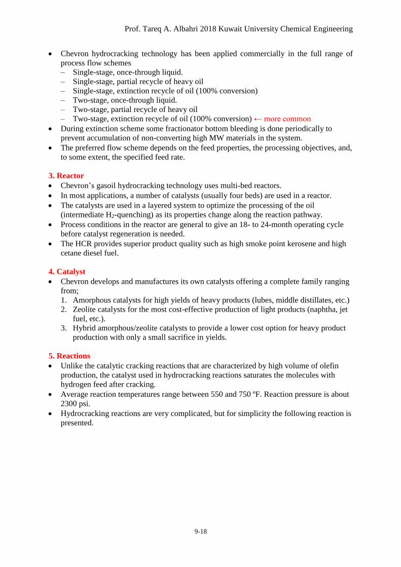
• Hydrocracking reactions are very complicated, but for simplicity the following reaction is
presented.
Petroleum Refining – Chapter 9: Conversion
9-19
Steps:
1. Cracking
2. Isomerization (rearrangement)
3. Saturation
Figure 9-9: A Simplified Hydrocracking reaction
HW
Hydrocracker material balance
+ +
Feed (Low API & small volume)
Products (High API & large volume)
Prof. Tareq A. Albahri 2018 Kuwait University Chemical Engineering
9-20
Figure 9-10: Simplified schematic Representation of the hydrocracking process
Petroleum Refining – Chapter 9: Conversion
9-21
Figure 9-11: Detailed schematic Representation of MAB refinery hydrocracking process