dual-wavelength control via phase-controlled optical feedback
TRANSCRIPT
Dual-wavelength control via phase-controlled optical feedbackPawlus, Robert
(2020)
DOI (TUprints): https://doi.org/10.25534/tuprints-00011917
Lizenz:
CC-BY-NC-ND 4.0 International - Creative Commons, Attribution Non-commerical,No-derivatives
Publikationstyp: Ph.D. Thesis
Fachbereich: 05 Department of Physics
Quelle des Originals: https://tuprints.ulb.tu-darmstadt.de/11917
VrijeUniversiteitBrussel
FACULTY OF ENGINEERINGDepartment of Applied Physics and Photonics
Dual-wavelength control viaphase-controlled optical feedback
A thesis submitted in fulfilment of the requirements for the awardof the degree of Doctor in Engineering by
Robert Pawlus
March 2020
Promoters: Prof. Dr. Martin VirteProf. Dr. Ir. Hugo ThienpontPriv. Doz. Dr. rer. nat. Stefan Breuer


Dual-wavelength control via phase-controlled optical feedback
To the faculty of Physicsof the Technische Universität Darmstadt
to obtain the academic degreeof a Doctor rerum naturalium (Dr. rer. nat.)
Dissertation ofM.Sc. Robert Pawlus
born in Darmstadt, Germany
First reviewer: Priv.-Doz. Dr. rer. nat. Stefan BreuerSecond reviewer: Prof. Dr. Martin Virte
Darmstadt 2020
D17

M.Sc. Robert Pawlus: Dual-wavelength control via phase-controlled optical feedbackVrije Universiteit Brussel, Belgium & Technische Universität Darmstadt, GermanyYear of publication: 2020
Date of public defence: 15.06.2020
Published under CC BY-NC-ND 4.0 Internationalhttps://creativecommons.org/licenses/
iv


Members of the Jury
Prof. Dr. Ir. Yves Rolain, chairmanDepartment of Fundamental Electricity and Instrumentation,
Vrije Universiteit Brussel, Belgium
Em. Prof. Dr. Ir. Roger Vounckx, vice-chairmanDepartment of Fundamental Electricity and Instrumentation,
Vrije Universiteit Brussel, Belgium
Prof. Dr. Ir. Nathalie Vermeulen, secretaryDepartment of Applied Physics and Photonics,
Vrije Universiteit Brussel, Belgium
Prof. Dr. Erwin Bente, examinerPhotonic Integration group,
Eindhoven University of Technology, Netherlands
Dr. Yanhua Hong, examinerSchool of Computer Science and Electronic Engineering,
Bangor University, United Kingdom
Prof. Dr. Benno Liebchen, examinerInstitute of solid-state physics,
Technische Universität Darmstadt, Germany
Prof. Dr. Martin Virte, promoterDepartment of Applied Physics and Photonics,
Vrije Universiteit Brussel, Belgium
Prof. Dr. Ir. Hugo Thienpont, co-promoterDepartment of Applied Physics and Photonics,
Vrije Universiteit Brussel, Belgium
Priv. Doz. Dr. rer. nat. Stefan Breuer, co-promoterInstitute of Applied Physics,
Technische Universität Darmstadt, Germany

A B S T R A C T
Lasers with the capability to emit simultaneously at two distinct wavelengths - so-calleddual-wavelength lasers - are highly desirable in several applications ranging from datacommunication, to the field of THz or sensing, but remain challenging to manufacture.Current solutions can typically be categorized in two groups. On the one hand, externalforcing can be used to make a largely multi-mode laser emit at only two wavelengths.These are highly versatile and flexible solutions but are typically obtained through com-plex and/or bulky setups. On the other hand, laser structures with intrinsic wavelengthselection appear to be way more robust but suffer from a lack of external control andflexibility; in short, these devices cannot be fine-tuned. In this PhD thesis, we propose,implement and experimentally demonstrate a simple technique for controlling the out-put of dual-wavelength lasers relying on a compact external structure that can be easilyintegrated monolithically with the laser.
This new technique is based on the Fabry-Perot effect of a phase controlled externalfeedback cavity. In short, the external cavity will slightly boost resonant modes whilethe non-resonant modes will see a slight increase of their losses. The phase control thenallows to select the resonating modes. As a result, setting the feedback cavity length toensure that the two distinct wavelengths emitted by the lasers are out-of-phase after acavity round trip allows to selectively boost or suppress one or the other wavelength ondemand.
To demonstrate the feasibility and relevance of the approach, we have first designedand implemented dual-wavelength lasers on a Photonic Integrated Circuit (PIC), usinga generic foundry platform. Because the proposed control technique would have theadvantage of being particularly compact, we rely on Distributed Bragg Reflectors (DBRs)as wavelength selective elements of the laser, thus obtaining a compact laser as well. Wehave designed different lasers using DBRs, placed sequentially or in parallel, to achievedual-wavelength emission combined with a broadband reflector or a third DBR. We thencoupled these devices with specifically designed external cavities including an electro-optic phase modulator and a semiconductor optical amplifier in order to control both,the feedback strength and the feedback phase.
After a detailed characterization of the dual-wavelength lasers and, in particular, aconfirmation that these were indeed successfully emitting at two distinct wavelengths,we have then explored the effect of the phase controlled optical feedback on the laseremission. Thus, we were able to confirm that the proposed technique could be consis-tently used to achieve complete extinction of each mode with suppression ratios as highas 50 dB. Despite varying performances across the different devices, the switching ap-
ix
peared to be particularly robust against most experimental variables. Moreover, we haverecorded switching times below 4 ns, which appeared to be mostly limited by the ownresponse time of the phase modulator, and which could potentially be reduced belowthe nanosecond timescale making it one of the fastest switching techniques currentlyavailable. Next, we have investigated the limitations of both the dual-wavelength laserand the control technique. Taking advantage of the large amount of measurements per-formed across several PICs and lasers, combined with a thorough numerical explorationof the parameter space, we were able to identify different directions of research for fur-ther optimizations. Improvements of the DBRs could lead to an improved wavelengthtunability that the external cavity could withstand, while the laser and external cavitystructure could potentially be optimized to achieve higher output power, higher sidemode suppression ratio and a more compact design. Last, but not least, the current re-sults strongly suggest that going from dual to multi (> 3) wavelength lasers could berealistically considered without significant conceptual changes.
To conclude, in this thesis, we propose a new solution to control dual-wavelengthlasers through a highly compact and efficient external structure which allows to balanceor switch the wavelength emission at will using a single control parameter: the opticalfeedback phase.
x

S A M E N VAT T I N G
Lasers met de mogelijkheid om gelijktijdig uit te zenden op twee verschillende golflengtenzijn zeer wenselijk in verschillende toepassingen, variërend van datacommunicatie tothet veld van THz of van detectie, maar blijven een uitdaging om te vervaardigen. Huidigeoplossingen kunnen doorgaans in twee groepen worden onderverdeeld. Enerzijds kanexterne forcering worden gebruikt om een grotendeels multi-mode laser te laten uitzen-den op slechts twee golflengten. Dit zijn zeer veelzijdige en flexibele oplossingen, maarworden meestal verkregen door complexe en / of omvangrijke opstellingen. Aan de an-dere kant lijken laserstructuren met intrinsieke golflengteselectie veel robuuster, maarlijden ze onder een gebrek aan externe controle en flexibiliteit; kortom, deze apparatenkunnen niet worden verfijnd. In dit proefschrift suggereren, implementeren en demon-streren we experimenteel een eenvoudige techniek voor het regelen van de output vanlasers met dubbele golflengte op basis van een compacte externe structuur die gemakke-lijk monolithisch kan worden geïntegreerd met de laser.
Deze nieuwe techniek is gebaseerd op het Fabry-Perot-effect van een fasegestuurdeexterne trilholte. Kortom, de uitwendige trilholte zal de resonantiemodi enigszins ver-sterken, terwijl de niet-resonerende modi een lichte toename van hun verliezen zullenzien. De faseregeling maakt het vervolgens mogelijk om de resonerende modi te se-lecteren. Als resultaat, laat het instellen van de lengte van de trilholte, zodat dat de tweeverschillende golflengten die door de lasers worden uitgezonden uit fase zijn na eenrondreis in de trilholte, toe om op verzoek selectief de ene of de andere golflengte teversterken of te onderdrukken.
Om de haalbaarheid en relevantie van de aanpak aan te tonen, hebben we eerst lasersmet dubbele golflengte ontworpen en geïmplementeerd op een fotonisch geïntegreerdcircuit (Photonic Integrated Circuit, PIC), met behulp van een generiek platform. Om-dat de voorgestelde regeltechniek het voordeel zou hebben dat deze bijzonder compactis, vertrouwen we op verdeelde Bragg-reflectoren (distributed Bragg reflectors, DBRs)als golflengte-selectieve elementen van de laser, waardoor we ook een compacte laserkrijgen. We hebben verschillende lasers ontworpen die DBRs gebruiken, zij het sequen-tieel of parallel geplaatst, om emissie met dubbele golflengte te bereiken in combinatiemet een breedbandreflector of een derde DBR. Vervolgens hebben we deze apparatengekoppeld aan speciaal ontworpen externe trilholtes, waaronder een elektro-optischefasemodulator en een halfgeleider optische versterker om zowel de terugkoppelsterkteals de terugkoppelfase te regelen.
xi

Na een gedetailleerde karakterisering van de lasers met dubbele golflengte en, inhet bijzonder, een bevestiging dat deze inderdaad succesvol opereerden bij twee ver-schillende golflengten, hebben we vervolgens het effect van de fasegestuurde optischefeedback op de laseremissie onderzocht. Zo konden we bevestigen dat de voorgesteldetechniek consistent kon worden gebruikt om elke modus volledig te onderdrukken metverhoudingen zo hoog als 50 dB. Ondanks verschillende prestaties op de verschillendeapparaten, bleek de omschakeling bijzonder robuust ten opzichte van de meeste exper-imentele variabelen. Bovendien hebben we schakeltijden vastgelegd onder de 4 ns, diemeestal beperkt bleken te zijn door de eigen reactietijd van de fasemodulator en die mo-gelijk zouden kunnen worden teruggebracht tot een tijdschaal onder de nanoseconde,waardoor het een van de snelste schakeltechnieken is die momenteel beschikbaar zijn.
Vervolgens hebben we de beperkingen van zowel de laser met dubbele golflengte alsde besturingstechniek onderzocht. Door gebruik te maken van het groot aantal metingenuitgevoerd op verschillende PICs en lasers, in combinatie met een grondige numeriekeverkenning van de parameterruimte, konden we verschillende onderzoeksrichtingenidentificeren voor verdere optimalisatie. Verbeteringen van de DBRs zouden kunnenleiden tot een verbeterde golflengteafstemming die ondersteund wordt door de externetrilholte, terwijl de laser en de externe trilholtestructuur mogelijk zouden kunnen wor-den geoptimaliseerd om een hoger uitgangsvermogen, een hogere onderdrukkingsver-houding in de zijmodus en een compacter ontwerp te bereiken. Tenslotte suggererende huidige resultaten sterk dat overgaan van tweevoudige naar meervoudige (> 3)golflengtelasers realistisch overwogen zou kunnen worden zonder significante conceptueleveranderingen.
Als conclusie stellen we in dit proefschrift een nieuwe oplossing voor om lasers metdubbele golflengte te besturen via een zeer compacte en efficiënte externe structuur diehet mogelijk maakt om de golflengte-emissie naar believen te balanceren of te schakelenmet behulp van een enkele regelparameter: de optische terugkoppelfase.
xii

Z U S A M M E N FA S S U N G
Laser mit der Fähigkeit gleichzeitig auf zwei Wellenlängen zu emittieren sind in ver-schiedenen Anwendungen, ausgehend von der Datenkommunikation über das Gebietder THz Generierung bis hin zu optischen Messeinrichtungen äußerst attraktiv, ihreHerstellung erweist sich jedoch als schwierig. Aktuelle Lösungen lassen sich in zweiGruppen unterteilen. Einerseits kann externes triggern verwendet werden, um einenmulti-modalen Laser auf nur zwei Wellenlängen emittieren zu lassen. Diese Lösungensind äußerst vielseitig und flexibel, benötigen jedoch in der Regel ausreichend Platzund resultieren in komplexen Aufbauten. Andererseits scheinen Laserstrukturen mit in-trinsischer Wellenlängenselektion robuster zu sein, jedoch mangelt es ihnen an externerKontrolle und Flexibilität, da sie nicht feinabgestimmt werden können. In dieser Dok-torarbeit wird eine einfache Methode zur Steuerung der Ausgangsleistung von Lasernmit zwei Wellenlängen vorgeschlagen, implementiert sowie experimentell demonstriert.Dabei wird eine kompakte externe Kavität verwendet, die monolithisch mit dem Laserintegriert werden kann.
Dieser neue Ansatz basiert auf dem Fabry-Perot-Effekt einer phasen-gesteuerten ex-ternen Rückkopplung. Resonante Moden werden durch die externe Kavität bevorzugt,während die anti-resonanten Moden erhöhte Verluste erleiden. Die Phasensteuerung er-möglicht dann die Auswahl der resonanten Moden. Durch justieren der Kavitätslängekann sichergestellt werden, dass die zwei von dem Laser emittierten Wellenlängen nacheinem Durchlauf der externen Kavität phasenverschoben sind und entweder die eineoder die andere Wellenlänge bei Bedarf selektiv bevorzugt oder unterdrückt werdenkann.
Um die Machbarkeit und Relevanz des Ansatzes zu demonstrieren, werden zunächstLaser mit zwei Wellenlängen auf einem optischen integrierten Schaltkreis unter Ver-wendung einer generischen Plattform entworfen und implementiert. Die vorgeschlageneSteuerungsmethode hat den Vorteil besonders kompakt zu sein, um auch Kompaktheitfür die Laser zu erreichen, werden Bragg-Reflektoren als wellenlängenselektive Elementegenutzt. Verschiedene Laser wurden unter der Verwendung dieser Reflektoren entwick-elt, die entweder sequentiell oder parallel angeordnet sind, um eine Emission auf zweiWellenlängen in Kombination mit einem Breitbandreflektor oder einem dritten Bragg-Reflektor zu erzielen. Diese Laser wurden dann mit individuell angepassten externenKavitäten gekoppelt, einschließlich eines elektrooptischen Phasenmodulators und einesoptischen Halbleiterverstärkers, um sowohl die Rückkopplungsstärke als auch die Rück-kopplungsphase zu steuern.
xiii
Nach einer detaillierten Charakterisierung der Laser und insbesondere einer Bestäti-gung, dass diese tatsächlich auf zwei unterschiedlichen Wellenlängen emittieren, wurdeder Effekt der phasengesteuerten optischen Rückkopplung auf die Laseremission unter-sucht. Auf diese Weise konnte die vorgeschlagene Methode in unterschiedlichen Lasernexperimentell demonstriert werden, um eine vollständige Unterdrückung der Wellen-längen mit Unterdrückungsverhältnissen von bis zu 50 dB zu erreichen. Trotz unter-schiedlicher Leistungen der verschiedenen Laser war das Schalten gegenüber den meis-ten experimentellen Variablen robust. Darüber hinaus konnten Schaltzeiten von unter4 ns demonstriert werden, die größtenteils durch die eigene Reaktionszeit des Phasen-modulators begrenzt zu sein scheinen und die möglicherweise unter die Nanosekunden-Zeitskala reduziert werden könnten, was ihn zu einer der schnellsten derzeit verfügbarenSchalttechniken macht. Als nächstes wurden die Einschränkungen sowohl des Zwei-wellenlängenlasers als auch der Steuerungsmethode untersucht. Dank einer Vielzahl vonMessungen, die an mehreren optischen integrierten Schaltkreisen und Lasern durchge-führt wurden, sowie einer theoretischen Untersuchung des Parameterraums, konntenunterschiedliche Aspekte für weitere Optimierungen identifiziert werden. Verbesserun-gen der Bragg-Reflektoren könnten zu einer besseren Abstimmbarkeit der Wellenlängenführen, die die externen Kavität kompensieren könnte, während die Laser- und externeKavität optimiert werden könnten um eine höhere Ausgangsleistung, ein höheres Un-terdrückungsverhältnis für die Seitenmoden und ein kompakteres Design zu erzielen.Zuletzt deuten die aktuellen Ergebnisse darauf hin, dass der Übergang von Lasern mitzwei zu mehreren Wellenlängen (> 3) ohne wesentliche konzeptionelle Änderungen inBetracht gezogen werden könnte.
Zusammenfassend wird in dieser Arbeit eine neue Methode zur Steuerung von Lasernmit zwei Wellenlängen durch eine kompakte und effiziente externe Kavität vorgeschla-gen, die es ermöglicht die Wellenlängenemission nach Belieben mithilfe eines einzigenSteuerparameters auszugleichen oder umzuschalten: der optischen Rückkopplungsphase.
xiv

C O N T E N T S
1 introduction on dual-wavelength lasers 1
1.1 Semiconductor lasers 2
1.2 Need for dual-wavelength lasers 5
1.3 Achieving dual-wavelength emission 6
1.4 Generic foundry platform as a user 9
1.5 Influence of optical feedback on lasers 12
1.6 Objectives and outline of this work 15
2 control approach for dual-wavelength emission 17
2.1 Control approach 18
2.2 Simulation model 20
2.3 Phase dependency of switching performance 23
2.4 Conclusion 33
3 integrated dual-wavelength lasers 35
3.1 Solitary laser layouts 36
3.2 Implementation on first PIC 40
3.3 Optimization of dual-wavelength concepts 44
3.4 Experimental setup 48
3.5 Characterisation of dual-wavelength lasers 50
3.6 Conclusion 56
4 amplitude control via phase-controlled optical feedback 57
4.1 Feedback cavity design on PIC 58
4.2 Impact of tuning the optical feedback delay 60
4.3 Exploring the parameter space 64
4.4 Switching speed 68
4.5 Conclusion 71
5 limitations of performances 73
5.1 Robustness against relative phase shift variations 74
5.2 Limitations observed 80
5.3 Improvements on lasers and feedback section 85
5.4 Conclusion 88
6 conclusion 89
xv

contents
6.1 Main achievements 90
6.2 Perspectives for future work 93
list of publications 95
bibliography 97
curriculum vitae 107
xvi

1 I N T R O D U C T I O N O ND U A L - WAV E L E N G T H L A S E R S
In this first chapter, the framework of this PhD thesis will be introduced and all necessaryfundamentals will be discussed to give the reader the necessary context and means tofollow the upcoming chapters. First, general basics on the laser emission in semiconduc-tor lasers will be introduced in section 1.1. Then the need for multi-wavelengths laserswill be discussed in section 1.2 together with an overview on how a multi-wavelengthemission can be achieved in section 1.3. Then, a brief introduction onto multi-project-waver platforms will be given in section 1.4 and the impact of optical feedback onto alaser will be discussed in section 1.5. Finally, the objectives of this thesis will be outlinedin the last section 1.6.
1

introduction on dual-wavelength lasers
1.1 semiconductor lasers
The first step towards the development of a laser was made by Albert Einstein with hisprediction of stimulated emission in 1917 [1]. Basically three different events can occur inan two-level energy system occupied by an electron: absorption, spontaneous emissionor stimulated emission as shown in Fig. 1.1. An incident photon with the correct energywill interact with an electron occupying the lower energy level and lift it into the higherenergy state while being absorbed in the process (a). The electron will relax at somepoint to reach thermal equilibrium by sending out a photon, releasing the energy in aprocess called spontaneous emission (b). However, if another incident photon interactswith the excited system, the photon will trigger the emission of another photon, identicalin wavelength, polarisation and orientation, this is called stimulated emission and is thefundamental basis of every laser (c).
Pumping
(Excitation)
Spontaneous
emission
Stimulated
emission
Upper energy
level
Lower energy
level
Electron
Photon
(c)(b)(a)
Figure 1.1: Two level energy system showing: (a) An incoming photon lifts an electron to a higherenergy level while being absorbed in the process. (b) Spontaneous emission of a photoninto a random direction with the electron relaxing to the lower energy state. (c) Stimu-lated emission with an incoming photon triggering the emission of an identical secondphoton.
To achieve a continuous-wave emission in a laser, the electron occupation in the upperenergy level needs to be higher than in the lower energy level, i.e. a population inver-sion is required. This is crucial so that stimulated emission dominates the spontaneousemission. Achieving a population inversion in a two-level energy system with pumpingis however impossible. The electrons of an atom in a thermal equilibrium mostly occupythe lower energy state. Incident radiation with the correct energy can only achieve apopulation of 50 % per energy level, no population inversion. A higher population of theupper energy level would otherwise be depleted by stimulated emission. Hence, threeand four energy level systems were considered to overcome this limitation. In these sys-tems, two energy levels serve as a radiative transitions with a long carrier lifetime forthe upper energy level and a very short carrier lifetime for the lower energy level tomaximize the population inversion. The other energy levels serve as pumping levels torefill the radiative energy levels as fast as possible with short carrier lifetimes.
With the development of semiconductor lasers, electrons could be injected right intothe upper energy levels to achieve the desired population inversion. Doping the semicon-ductor material improves its conductivity and allows the transport of the carriers to thearea where the two materials are connected, the depletion zone. A p-doping improves
2

1.1 semiconductor lasers
(a) (b)
Figure 1.2: In (a), a pn-junction showing the lack of carrier confinement which results in a lowcarrier population. In (b), a double-hetero-junction with three materials varying in theirband gaps confine the carriers in a small region, leading to better performances [2].
the conductivity for the holes while n-doping improves the conductivity for the elec-trons. In the depletion zone, the recombination process between the carriers occurs andphotons are emitted in the process as shown in Fig. 1.2 (a). However, the confinementof these transitions is poor and results in bad efficiencies and even requires pulsed oper-ation due to heat dissipation. Single- and later double-hetero-structures were proposedto overcome these issues and spatially confine the electrons and photons to the sameregion in order to lower the threshold currents and is shown in Fig. 1.2 (b). This im-proved the efficiency and lead to continuous-wave operation with high powers at roomtemperature [3], [4].
Bulk Quantum well Quantum wire Quantum dot
Figure 1.3: Energy confinement of the material structure: Bulk material with a continuous energystates. Confining the material in one direction results in a Quantum-well structure withstepwise energy states. Confining the material in two directions results in Quantum-wires with a sawtooth like energy states. A confinement in three directions results inQuantum-dots with discrete energy states. [5]
Further extensive developments aimed to improve the carrier localisation to specific en-ergy states to achieve even higher efficiencies with higher output powers and lower laserthresholds. The dimensions of the active material was changed in the process as shownin Fig. 1.3. The p-n-junction of the first lasers correspond to the bulk material shown on
3

introduction on dual-wavelength lasers
the left. This structure has a density-of-states which results in a distributed carrier pop-ulation, spread out over a lot of different energy states. Reducing the dimension by oneleads to so called Quantum-well structures which improve the carrier population of thelowest energy state due to its step function. This improves the confinement of the carriersto a specific energy state and consequently to lower thresholds and higher optical outputpowers. Quantum-wires have an even higher carrier confinement, but require additionalmanufacturing steps and are therefore not first choice. Quantum-dots allow to constrainthe electrons to discrete energy states resulting from their small dot-sizes and allow fordiscrete radiative transitions. The lowest three energy levels are called the ground-state,the excited-state and the second-excited-state. Emission either on the ground state or theexcited state are most common in quantum-dot lasers. Achieving simultaneous emissionon both states has first been shown in [6] and simultaneous emission on all three stateshas been demonstrated in [7]. However, the dots vary in size as they are grown by a selfassembling process which results in varying dot sizes and consequently varying energystates which usually results in a multi-mode emission for each energy state.
4

1.2 need for dual-wavelength lasers
1.2 need for dual-wavelength lasers
Dual-wavelength lasers, or in general multi-wavelength lasers, are relevant for variety ofapplications. The following application fields show the diversity in which multiple wave-lengths could be advantageous. These applications use at least two different wavelengthto transmit or obtain more information than single wavelength laser would allow for:
• Telecommunication applications are the major driving force for the integration ofmulti-wavelength laser sources [8], [9], [10], [11]. To increase the data transmis-sion rates, multiple-wavelength are used to transport large amount of informationthrough a single fibre using wavelength division multiplexing. Increasing the num-ber of wavelengths allows to transmit even more information which leads to theconstant development in this direction.
• Dual-wavelength laser in particular are interesting for THz based applications liketomographic imaging [12] or spectroscopy [13]. THz sources usually require twodistinct wavelengths superimposed in an active medium to generate a beat fre-quency, the electrons follow this beat frequency and subsequently emit THz radia-tion [14], [15], [16], [17].
• For spectroscopy applications, multiple wavelengths can be used to measure differ-ent absorption regions at once, or measure a reference at the same time to eliminateenvironmental background effects. A multi-wavelength laser, covering different ab-sorption regions could therefore be very attractive [18], [19], [20].
• For sensing applications, e.g. structural health monitoring [21], [22], optical fibreswith inscribed Fibre-Bragg-Gratings are used to detect strain and temperature vari-ations. A cost-effective method is to sequentially read out one sensor after the otherusing a tunable single-wavelength laser. However, multi-wavelength lasers couldaddress multiple sensors at once and could even allow for a continuous measure-ment process of each sensor.
• Dual wavelength lasers are also of interesting in Lidar systems. They have beenused to improve the measurement techniques for forest mappings to distinguishbetween the canopy and the forest ground [23] or to distinguish between leafs andthe stem for high accuracy measurements [24]. Dual wavelength lasers have alsobeen used for velocimetry to measure the speed of a moving object [25]. Opticalfeedback of the two wavelength has been used to determine the objects velocitybased on the resulting beat-frequency in the gain medium.
Generating multi-wavelength emission is however not straightforward, especially whencompactness, robustness and energy efficiency is desired. Another challenge is also theircontrol to precisely achieve the emission properties required in the applications men-tioned. In the following, we give an introduction on the generation of two wavelengthsand point out the challenges.
5

introduction on dual-wavelength lasers
1.3 achieving dual-wavelength emission
Laser emission can be achieved by considering a Fabry-Perot resonator where the opticalwave is travelling forth and back while being amplified by stimulated emission in theprocess. For a stable resonance, the amplitude as well as the phase have to match theinitial condition after a full cavity round trip of two times the laser lengths L. If the
amplitude condition is met, it follows for the gain g, that g = a+ 12L ln
(1rl·rr
), with the
losses a and reflectivities rr & rl of the right and left mirror, respectively. Laser emissioncan be achieved if the gain exceeds the losses and it holds (g− a) > 0. The reflectivitiesof the resonator mirrors play a crucial role as they define the optical output power. Insemiconductor lasers, these mirrors are usually formed by the edges of the laser chipwhen cleaving a wafer into individual lasers. Additional higher- and lower-reflectioncoatings can be applied to modify the reflectivities to increase the optical output power.To achieve a standing wave inside the laser cavity, the phase condition has to be metas well and only modes with multiples of λ/2 can resonate in a laser. However, due tothe width of the gain spectrum, this condition is satisfied for a large number of differentwavelengths. The resonator provides a broadband feedback which can result in a multi-mode emission for all modes satisfying the amplitude condition of (g− a) > 0 [4]. Torestrict the emission to a single mode, different ways can be followed.
A broadband mirror can be used to apply an external feedback to the laser. Adjustingthe feedback length such that the phase condition is only met for one specific mode inthe laser cavity, allows to select and boost this wavelength. Alternatively, the mirror canbe exchanged with a diffraction grating as a wavelength selective element to force thelaser emission only on one mode. This also comes with the advantage of a wavelengthtunability over the whole gain spectrum, but the mechanical and thermal stabilisationrequires huge efforts and these lasers are not well suited for mass manufacturing. Inte-grated solutions are interesting alternatives and the implementation of the laser togetherwith wavelength selective elements onto a single device is desired. One solution is toreplace the cavity mirrors with Distributed-Bragg Reflectors (DBRs) to provide a verynarrow reflection window with the advantage of a wavelength tunability [26]. A simi-lar solution is the implementation of the periodic grating right into the active region ofthe laser, i.e. to obtain a distributed feedback laser [27]. These type of lasers tend to bespectrally more stable as the reflections happen continuously along the laser. Overall,implementing Bragg reflectors improves the wavelength selectivity and stability of thesingle wavelength source and has low manufacturing costs due to the mass manufactur-ing capabilities.
Achieving an emission simultaneously on two different wavelengths is more challeng-ing and balancing their optical powers can be achieved in multiple ways. Two simpleways are free space solutions, either based on superimposed light beams, optical injec-tion [30] or on laser sources with external optical feedback, e.g. external grating feed-back with two mirrors to select two different wavelengths. These are quite versatileapproaches as their wavelengths and relative optical powers can be controlled sepa-rately [31], [32], [33]. However, as already discussed, they result in bulky setups andpose a challenge in their alignment as well as in their mechanical and thermal stabiliza-tion, hence, full integration is desired. Implementing separate discrete laser sources and
6
1.3 achieving dual-wavelength emission
(a) (b)
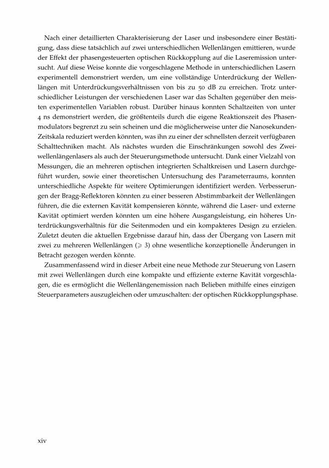
Figure 1.4: Discrete dual wavelength lasers: (a) Two parallel arranged distributed feedback laserswith a Y-junction to merge their beams [28]. (b) Two sequentially arranged DBRs toachieve the emission on two different wavelengths [29].
merging their beams on the chip overcomes some of these disadvantages. In [34], [35]and [28], discrete laser sources were implemented in parallel and their beams weremerged using a Y-shaped combiner as shown in Fig. 1.4 (a). In [36], two sequentiallyarranged sources were implemented in a vertical-cavity surface-emitting laser. Thesesources are very promising but are individual lasers with separated carrier reservoirs.Hence, they are unsuited for applications where the carrier coupling is crucial, e.g. forTHz or mmWave generation. Laser sources with a single gain section and two identicalDBRs were proposed to overcome this limitation [37], [29] as shown in Fig. 1.4 (b). TheDBRs were arranged sequentially and provide single-mode emission when no DBR isbiased. Detuning one of the DBRs, results in a tunable wavelength separation between0.3 nm and 6.9 nm. A similar design was proposed in [38] with detuned DBRs rightaway.
Another way to achieve a dual-wavelength emission is to restrict the possible energytransitions directly in the gain material, e.g. semiconductor lasers with intrinsic multi-wavelength selection like edge-emitting quantum-dot lasers [39]. These lasers can emitsimultaneously from two different energy levels at the same time, but usually require spe-cific operating conditions. For two-section lasers, asymmetrically biasing allows to tunethe optical losses in the absorber section and has proven to achieve dual-wavelengthemission [40], [41], [42]. A similar approach to control the emission was achieved byconnecting the absorber section to ground over a tunable resistor [43]. Tuning the resis-tor tuned the losses in the cavity and allowed to either switch between the individualstates or to achieve a simultaneous emission on both states simultaneously. Quantum-dotlasers have shown to be highly temperature dependent, tuning the temperature allowsto either select specific states or to achieve a simultaneous emission [44], [45]. Anotherissue of these lasers is their Fabry-Perot cavity which leads to an emission on multiple-modes within each state [46]. Similar solutions to limit the number of emitting modeshave already been discussed above for single-wavelength lasers. In [47], a phase sensi-tive broadband optical feedback was applied and the length of the external feedbackcavity was tuned in a sub µm range. This lead to a recurring, but limited exchange inoptical power between the two states. Further studies revealed the emergence of multi-ple longitudinal modes within each state to show energy exchanges between each other,
7

introduction on dual-wavelength lasers
being the limiting factor for a full control of both states [48]. External grating feedbackwas applied to limit the number of modes per state in other experiments [25], [48], [45].More sophisticated solutions embedded distributed feedback gratings into their lasers toachieve a single mode emission [42]. The grating was coupled only to the excited-stateof the laser while the ground-state emitted on multiple modes. Asymmetrically biasingthe two sections also allowed for a single-mode emission on the ground-state.
Besides these huge efforts to control the laser emission, another challenge is the repli-cation of quantum-dot lasers. As their properties are highly dependent on the dot size,achieving a reliable manufacturing process is challenging. Even the embedded gratingsappeared to be insufficient to gain complete control over the dual-wavelength emission.Achieving stable and controllable dual-wavelength laser emission is a challenge, and itseems particularly hard to overcome all current limitations with a single device. Smartschemes therefore seem to be required to achieve dual-wavelength emission with a rel-atively simple structure. In this context, the design and manufacturing of Photonic In-tegrated Circuits through a generic foundry platform and Multi-Project-Wafer runs ap-pears as a practical and convenient solution and will be introduced in the next section.
8
1.4 generic foundry platform as a user
1.4 generic foundry platform as a user
Generic foundry platforms offer an easy and affordable access to a mass manufactur-ing process to build customized Photonic-Integrated-Circuits (PICs). The Multi-Project-Wafer (MPW) approach allows different participants to share a wafer and thus, to reducethe costs. Different platforms are available: Silicon , TriPleX and Indium-Phosphide. TheSilicon and TriPleX platforms focus on passive components with low propagation lossesand CMOS integration. This makes these platforms very attractive for hybrid integrationtogether with other platforms as lasers can not be directly manufactured using this tech-nology. Indium Phosphide (InP) targets the telecom wavelengths around 1550 nm. Twofoundries offer a participation with similar performances, the Fraunhofer Heinrich HertzInstitute (HHI) located in Berlin, Germany and SMART Photonics located in Eindhoven,The Netherlands. For this thesis, SMART Photonics has been chosen as a foundry dueto earlier participations, the well known processes and the lower costs which allow formore development cycles in the course of a PhD. Each participant has an predefined areafor a custom design and several copies of this design are distributed over the wafer anddiced into individual PICs after manufacturing. Although identical in design, they mightperform differently due to their location on the wafer. Multiple active and passive ele-ments can be implemented onto such a PIC to achieve a high density of components. Toease the use and to allow an easy access to these platforms also for non-experts, a librarywith predefined building blocks is provided by the foundry. A thorough overview overthe development of the photonic integration technology is given in [49], [50], [51], [52]and [53]. Only the most important aspects for each component are given in the followingto be able to understand the laser concepts presented in this thesis.
• SOA: The semiconductor-optical-amplifier (SOA) is based on a Quantum-well struc-ture and is mainly used for light amplification. At threshold, the center frequencyof the gain spectrum is around 1550 nm. With increasing gain current the gaindominantly increases for shorter wavelengths up to a total width of about 150-200 nm [49]. The length is the only parameter which can be adapted in the designprocess.
• Waveguide: The waveguides are used to direct the light on the chip and can be im-plemented with two different etching depths for strong and weak confinement ofthe light. Shallowly etched waveguides allow to guide the light with lower losses,however, result in low bending radii because of the low refractive index contrast.Deeply etched waveguides have slightly higher losses, but allow for much smallerbending radii which is beneficial wherever compactness is crucial. Several prede-fined shapes are provided, usually the length and radius, as well as offset in caseof S-bend waveguides, can be adapted.
• Isolation section: These components are required to avoid cross talk between dif-ferent active components. They are based on waveguides but with the conductivetop cladding removed to avoid current leakage. The length can be adapted anddetermines the resistance of the component.
• MMI splitter: Multimode-Interference (MMI) splitters are used wherever a signalhas to be split or merged. Different numbers of input and output ports are available.
9
introduction on dual-wavelength lasers
1x1 MMI splitters can be used to remove higher order transversal modes. 1x2 MMIsplitters are used to split up or merge a signal with a ratio of 3 dB. 2x2 MMIsplitters can also provide a splitting ratio of 3 dB as well as odd splitting ratios. Inthe laser concepts presented in this thesis, splitting ratios of 85:15 are used.
• MIR: Multimode-Interference-Reflectors (MIRs) are broadband mirrors, availablewith a single or a double input port. The 1-port version acts as a normal mirrorwhile the 2-port version can be used to split light with a 50:50 ratio when light issend in via one channel. These 2-port MIRs are ideal as a outcoupling mirror forlaser cavities.
• EOPM: The Electro-optical-phase-modulator (EOPM) allows to change the phaseof the light when a negative voltage is applied. The electro optic effect changes therefractive index and subsequently the optical path length. The EOPM can only beadapted in length, a voltage of 8 V allows for a phase shift of π for a 1 mm longEOPM section.
• Transition section: Various building blocks are available in different etching depths,depending if low losses or compactness is desired. However, some building blockslike SOAs are only available in shallow etching. To be able to connect differentetching depths, transition sections are provided.
• DBR: Distributed-Bragg-Reflectors (DBRs) are narrow bandwidth mirrors. Due tothe material choices made by the foundry, their coupling coefficient is fixed to50 cm−1 and only the length and the pitch can be adapted. The maximal DBRlength is 500 µm with a reflectivity of 97 %. The pitch can be adapted to achievethe desired central DBR wavelength. The fixed coupling coefficient results in a fixedrelation between the DBR length, its spectral bandwidth and the reflectivity.
• Metal track: The metal track is used to route electrical connections across the PICand can cross waveguides. It can be adapted in length and width to adapt for therequired current of a component.
Implementing a custom design using this set of building blocks also requires the com-pliance to safety margins between different components. This can make fitting a densedesign onto a PIC challenging and time consuming. Each active component has a metalcontact and can either be probed by a needle or routed to the edge of the PIC using themetal tracks for packaging. Packaging solutions are provided by independent companiesand ease the use of the PICs for electrical and optical connectivity.
Different multi-wavelength lasers emitting around 1550 nm have already been imple-mented using such platforms. In Fig. 1.5 (a), multiple lasers were combined using anarrayed waveguide grating to achieve a 16-channel laser source with spectral separationsof 0.8 nm [54]. A similar laser has been demonstrated in [57] with 8 channels. The ar-rayed waveguide grating allows to merge the beams of the 16 different laser sources intoone single beam for outcoupling and also serves as a intracavity wavelength selectiveelement. The laser itself is a Fabry-Perot resonator formed by the edges of the PIC, se-lection of a specific wavelength is achieved by biasing the corresponding SOA channel.In (b), a four-channel Fabry-Perot laser, spectrally separated by 3.2 nm, was demon-strated [55]. Here, the arrayed waveguide grating is used to apply a wavelength selective
10
1.4 generic foundry platform as a user
(a)
(b)
(c)
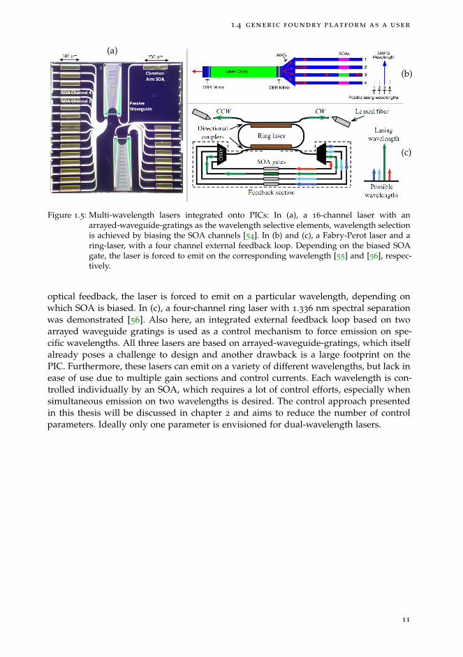
Figure 1.5: Multi-wavelength lasers integrated onto PICs: In (a), a 16-channel laser with anarrayed-waveguide-gratings as the wavelength selective elements, wavelength selectionis achieved by biasing the SOA channels [54]. In (b) and (c), a Fabry-Perot laser and aring-laser, with a four channel external feedback loop. Depending on the biased SOAgate, the laser is forced to emit on the corresponding wavelength [55] and [56], respec-tively.
optical feedback, the laser is forced to emit on a particular wavelength, depending onwhich SOA is biased. In (c), a four-channel ring laser with 1.336 nm spectral separationwas demonstrated [56]. Also here, an integrated external feedback loop based on twoarrayed waveguide gratings is used as a control mechanism to force emission on spe-cific wavelengths. All three lasers are based on arrayed-waveguide-gratings, which itselfalready poses a challenge to design and another drawback is a large footprint on thePIC. Furthermore, these lasers can emit on a variety of different wavelengths, but lack inease of use due to multiple gain sections and control currents. Each wavelength is con-trolled individually by an SOA, which requires a lot of control efforts, especially whensimultaneous emission on two wavelengths is desired. The control approach presentedin this thesis will be discussed in chapter 2 and aims to reduce the number of controlparameters. Ideally only one parameter is envisioned for dual-wavelength lasers.
11
introduction on dual-wavelength lasers
1.5 influence of optical feedback on lasers
Semiconductor lasers have very high conversion efficiencies from electricity to light byup to 73 % [58], hence, laser oscillation is achieved even for low facet reflectivities. Semi-conductor lasers with cleaved facets have reflectivities of about 30 % and to improveefficiency, highly reflective coatings are applied to the back facet and low reflective coat-ings are applied to the front facet [59]. This leads to the fact that semiconductor lasersare easily affected by back reflections from any optical component and usually opticalisolators are used. The optical feedback can have various effects, it can be used to se-lect modes, to suppress side modes, to stabilise the laser emission and can also lead todynamical behaviour.
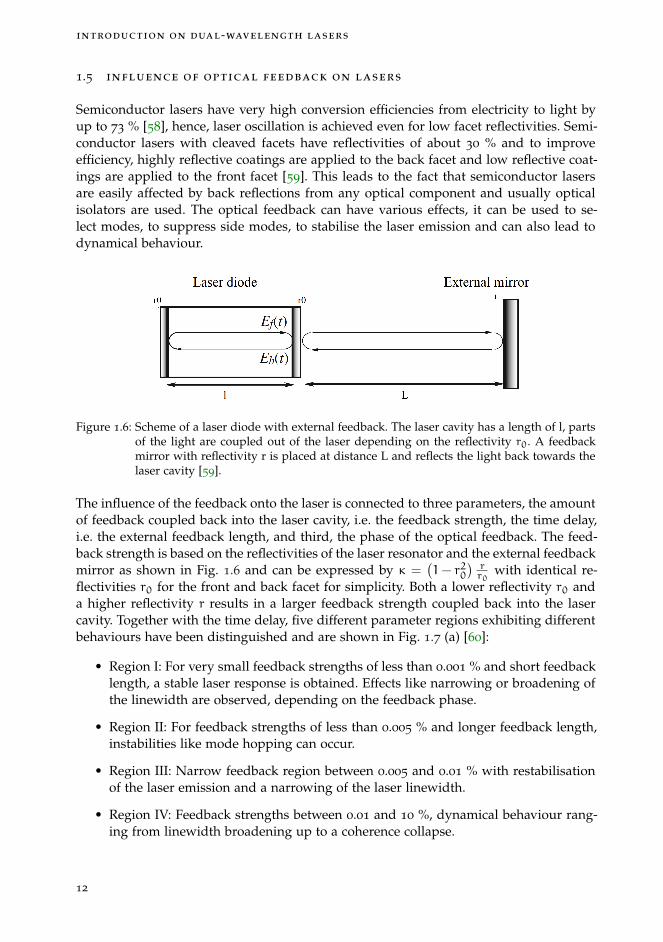
Figure 1.6: Scheme of a laser diode with external feedback. The laser cavity has a length of l, partsof the light are coupled out of the laser depending on the reflectivity r0. A feedbackmirror with reflectivity r is placed at distance L and reflects the light back towards thelaser cavity [59].
The influence of the feedback onto the laser is connected to three parameters, the amountof feedback coupled back into the laser cavity, i.e. the feedback strength, the time delay,i.e. the external feedback length, and third, the phase of the optical feedback. The feed-back strength is based on the reflectivities of the laser resonator and the external feedbackmirror as shown in Fig. 1.6 and can be expressed by κ =
(1− r20
)rr0
with identical re-flectivities r0 for the front and back facet for simplicity. Both a lower reflectivity r0 anda higher reflectivity r results in a larger feedback strength coupled back into the lasercavity. Together with the time delay, five different parameter regions exhibiting differentbehaviours have been distinguished and are shown in Fig. 1.7 (a) [60]:
• Region I: For very small feedback strengths of less than 0.001 % and short feedbacklength, a stable laser response is obtained. Effects like narrowing or broadening ofthe linewidth are observed, depending on the feedback phase.
• Region II: For feedback strengths of less than 0.005 % and longer feedback length,instabilities like mode hopping can occur.
• Region III: Narrow feedback region between 0.005 and 0.01 % with restabilisationof the laser emission and a narrowing of the laser linewidth.
• Region IV: Feedback strengths between 0.01 and 10 %, dynamical behaviour rang-ing from linewidth broadening up to a coherence collapse.
12

1.5 influence of optical feedback on lasers
• Region V: Large feedback strengths beyond 10 %, extended cavity regime withthe laser operating as a long cavity laser with a short active region. Usually ananti-reflection coating is required to reach this region.
(a)
(b)
Figure 1.7: In (a), five different regions describe stable to unstable laser behaviour, depending onthe feedback strength and feedback delay [60]. In (b), for the short cavity regime (verti-cal dotted line) and for C < 1, stable emission can be achieved even for high feedbackstrengths [61].
However, the behaviours in these regions have been observed for long time delays, i.e.when the delay is longer than the period of the relaxation oscillation frequency of thelaser. In Fig. 1.7 (b), the stability of a laser with a short feedback cavity is shown. Thefeedback cavity round trip time corresponding to the relaxation frequency is indicatedby the vertical dotted line at τνr. For all lengths longer than this, unstable regions arefound as discussed above. However, for shorter feedback lengths below the relaxationoscillation frequency, even high feedback strengths do not destabilize the laser. Therefore,the short cavity regime is considered to be more stable than the long cavity regime. Thisstability information has been expressed with the C-parameter as a first approximationfor stability. It takes the feedback strength and feedback length of the laser into accountand reads as follows: C = κτ
τin
√1+α2. τ and τin are the external and internal round
trip times, respectively, and α the linewidth enhancement factor. As visible in Fig. 1.7 (b),values of C < 1 are a first indication of a stable laser operation under optical feedback.
Besides the feedback strength and length, also the feedback phase can have a crucialimpact on the laser emission. Tuning the feedback phase for single wavelength lasersusually tunes the outcoupling losses and results in changes of the output power or canresult in a narrowed or broadened linewidth as mentioned for feedback region I. How-
13
introduction on dual-wavelength lasers
ever, when considering two modes, also two different feedback phases have to be takeninto account.
Each mode can have a different feedback phase when coupled back into the laser cavityand two extreme cases can occur. Either both of these feedback phases are are identical,i.e. they are in phase, or they are out of phase. While the former results in modulationsof the output power like in the single-mode case, the latter has a much more complexinfluence on the laser and has been studied in [47] and [48]. In these works, changes of
2 4 6 8 100
5
10
15
Ou
tpu
t p
ow
er
(a. u
.)
Piezo−actuator displacement (µm)
0
0.01
0.02
Piezo-actuator displacement (µm)
0O
utp
ut P
ow
er
(a. u
.)1 20
(b)(a)
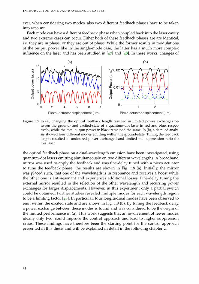
Figure 1.8: In (a), changing the optical feedback length resulted in limited power exchanges be-tween the ground- and excited-state of a quantum-dot laser in red and blue, respec-tively, while the total output power in black remained the same. In (b), a detailed analy-sis showed four different modes emitting within the ground-state. Tuning the feedbacklength resulted in undesired power exchanged and limited the suppression ratio forthis laser.
the optical feedback phase on a dual-wavelength emission have been investigated, usingquantum-dot lasers emitting simultaneously on two different wavelengths. A broadbandmirror was used to apply the feedback and was fine-delay tuned with a piezo actuatorto tune the feedback phase, the results are shown in Fig. 1.8 (a). Initially, the mirrorwas placed such, that one of the wavelength is in resonance and receives a boost whilethe other one is anti-resonant and experiences additional losses. Fine-delay tuning theexternal mirror resulted in the selection of the other wavelength and recurring powerexchanges for larger displacements. However, in this experiment only a partial switchcould be obtained. Further studies revealed multiple modes for each wavelength regionto be a limiting factor [48]. In particular, four longitudinal modes have been observed toemit within the excited state and are shown in Fig. 1.8 (b). By tuning the feedback delay,a power exchange between these modes is found and was considered to be the origin ofthe limited performance in (a). This work suggests that an involvement of fewer modes,ideally only two, could improve the control approach and lead to higher suppressionratios. These findings have therefore been the starting point for the control approachpresented in this thesis and will be explained in detail in the following chapter 2.
14

1.6 objectives and outline of this work
1.6 objectives and outline of this work
In this PhD thesis we aim at gaining a full control over dual-wavelength semiconductorlasers using optical feedback. In particular, the goal is to enable fine tuning of the opticaloutput powers between two wavelengths, ideally by only tuning a single parameter,which is the optical feedback phase. The main objectives are:
• First, identify the critical parameters for this control approach using theoreticalinvestigations. Then, determine optimal parameters for the optical feedback cavityto achieve the most efficient switching. Then, evaluate the control capability ofthe dual-wavelength emission by only changing the feedback parameters. Finally,address the effect of the feedback phase onto the switching capabilities as well asonto the robustness and limitations when changing their values.
• Second, demonstrate the control approach with on-chip devices including an inte-grated optical feedback cavity. Using an MPW approach, we aim to design differentdual-wavelength lasers and implement them together with our proposed controlapproach onto a PIC.
• Using this demonstrator, we aim to achieve significant insights on the dual-wavelengthswitching properties, in particular the extinction ratios and switching speeds. Asour lasers are designed to only emit on two distinct modes, we expect to achievehigh extinction ratios of at least 20 dB, exceeding previous demonstrations [47].Moreover, as the phase modulator allows for very fast modulations, we also expectto obtain switching times in the low nano-second range [62].
• Finally, using an independent laser system with a variable external feedback, weaim to evaluate the switching potential and degree of extinction for different feed-back delays and different feedback strengths. This will allow us to identify thelimitations of this control approach and possibly propose improvements for futuredesigns.
This thesis is structured as follows:
In chapter 2, we present the proposed control approach. The general idea is based on arelative phase shift between the involved modes as we will highlight in detail. We willuse a numerical model to study the peculiarities of the phase sensitive optical feedbackto better understand the behaviour when the feedback parameters are changed. We willthen use these simulations to determine the ideal operating conditions for our lasersand will also use them to determine the required external cavity length and feedbackstrength to achieve optimal performances.
In chapter 3, we present the design of customized dual-wavelength lasers. First, wepresent different laser concepts as well as simulations to determine the exact emittingwavelengths for each laser. Then we discuss the experimental setup and characteristicsfor each laser together with a DBR and temperature analysis.
In chapter 4, we discuss the implementation of our lasers and the feedback cavity ontoa PIC. First, we design tailored feedback cavities using the wavelengths determined in
15

introduction on dual-wavelength lasers
the simulations in chapter 3, and implement them onto the PIC. Then, we present ex-perimental results when tuning the feedback phase and discuss the operating rangeunder varying laser and feedback conditions. Last but not least, we present results onthe switching speed.
In chapter 5, we highlight the limitations of our lasers as well as the control approach.First, we adapt the control approach to two discrete devices, a quantum-dot laser and aexternal cavity diode laser to study the performance under varying feedback delays andspectral separations. Then, we will discuss the limitations on the DBR performances andpropose improvements for different laser concepts as well as for the feedback cavity.
In chapter 6, we will summarize the contributions of this work and outline future re-search topics to further advance this control technique towards an implementations forfuture applications.
16

2 C O N T R O L A P P R O A C H F O RD U A L - WAV E L E N G T H E M I S S I O N
In this chapter, we propose a novel control approach for dual-wavelength lasers basedon a phase sensitive optical feedback and study it by simulations. In the first section 2.1,we will introduce the concept of this approach in detail. Then, we will use a theoreticalmodel to describe the two electric fields with their individual feedback phases in sec-tion 2.2. Using the two feedback phases, we will map all possible relative phase shiftsbetween them and study varying laser and feedback parameters to identify the most effi-cient control performance in section 2.3. We will then reduce the parameter space to theparameters addressable in the experiment and study the requirements on the feedbackstrength to achieve an equal optical output power between the wavelengths. Then, wefurther reduce the parameter space to only two points in the phase space exhibiting thebest switching capabilities. With this, we will be able to study variations of the injectioncurrent and feedback strength onto different intrinsic laser parameters. Finally, we willstudy the switching speed to identify the best operating points for a fast switch.
17

control approach for dual-wavelength emission
DWL
Mirror
Phase
modulator(a)
Round trip time (a.u.)
Rea
l(E)
(a.u
.)
(b)
T1 T2
Figure 2.1: In (a), a schematic representation of the proposed control approach is shown, the dual-wavelength laser emits on λ1 & λ2. The laser facet and the mirror form the externalfeedback cavity consisting of a phase modulator. In (b), the spectral evolution of λ1 &λ2 into the feedback cavity is shown, exhibiting a relative phase shift of π around thepoints T1 & T2. With the mirror positioned such that (T1) is resonant to the lasing modeafter a full cavity round trip, a boost for λ1 achieved while λ2 experiences extra losses.The phase modulator allows to tune the optical path length towards a resonance of λ2indicated by (T2).
2.1 control approach
The fundamental idea of the control approach proposed in this thesis exploits the Fabry-Perot effect in the optical feedback cavity. The schematic of a dual-wavelength laser withan external feedback cavity is considered in Fig. 2.1 (a). If a wavelength emitted by thelaser resonates in the external feedback cavity, it will receive a boost in gain. If the wave-length is anti-resonant, it will experience additional losses and is disfavoured. For twodifferent wavelengths, the ideal case would be to achieve resonance for one wavelengthand anti-resonance for the other. This way, the resonant wavelength is boosted whilethe second wavelength is disfavoured. To achieve this condition, the evolution of twodifferent wavelengths into a feedback cavity is considered in Fig. 2.1 (b). The two wave-lengths evolve differently into the feedback cavity with an increasing relative phase shiftbetween them. For resonance of one wavelength and anti-resonance for the other, ide-ally a relative phase-shift of π has to be achieved after a full round trip in the feedbackcavity as indicated with (T1). Changing the emission in favour of the suppressed wave-length can be done by changing the optical path length, i.e. changing the cavity roundtrip time, to achieve resonance for the second mode indicated with (T2). In a free-spacesetup, changing the optical path length can be achieved by fine-delay tuning the externalmirror using a piezoelectric-actuator. However, for improved stability, speed and preci-sion, a monolithic solution should be preferred by using a phase modulator as shown in(a). The phase modulator uses for instance the electro-optic effect to change the refractiveindex and subsequently the optical path length when a voltage is tuned. If the two wave-lengths are spectrally close to each other, they will experience the same refractive indexchanges and the Fabry-Perot effect can be tuned in favour of the second mode (T2). The
18

2.1 control approach
Round trip time (a.u.)
Re
al(E
) (a
.u.)
T1
T2
T3
Figure 2.2: Evolution of three spectrally equidistant modes. The ideal relative phase shifts for theircontrol is 2π/3. T1, T2 & T3 correspond to the ideal feedback cavity round trip for themto be resonant and favoured for emission. The cavity length to achieve this relativephase shift depends on the number of modes and differs for the cavity length shownin Fig. 2.1.
position of the points (T1) & (T2) depend on the spectral separation of the wavelengths,hence, the round trip time has to be adapted for each individual dual-wavelength laser.
This control approach is not limited to just two wavelengths but can be extended ton wavelengths. For this, an equidistant distribution of the phase shifts ∆φ between thewavelengths has to be achieved, meeting the condition ∆φ = 2π/n. For two modes aphase shift of π is ideal while for three modes a relative phase shift of 2π/3 is optimaland is shown in Fig. 2.2. The ideal round trip times to select a specific wavelength areindicated with T1, T2 & T3 and can be addressed using a phase modulator. The maximalnumber of wavelengths which can be controlled using a single feedback section hasyet to be determined. In this PhD thesis, we aim to demonstrate the feasibility of thiscontrol approach using only two wavelengths to study its peculiarities, demonstrate theapproach experimentally and determine its limits. These insights could then be used tofurther develop this approach towards a multi-wavelength control in the future.
The performance of the control approach is dependent on two types of parametersthat we classify as intrinsic versus addressable parametersand will be introduced inthe following section 2.2. The intrinsic parameters are laser based parameters like thegain difference between the two wavelengths and the mode coupling. As the controlapproach is based on modulating the gain in the laser cavity, an identical gain for bothwavelengths is desired. If the gain difference is too large or the carrier coupling tooweak, a compensation might not be possible or only a partial switch might be achieved.Both of these parameters can not be controlled and are device dependent. Howeveraddressable parameters like the optical feedback strength or the injection current canbe controlled and allow to compensate for suboptimal intrinsic parameters. To assessthe degree in which this is possible, we perform numerical simulations to study theparameter dependencies in the following.
19

control approach for dual-wavelength emission
2.2 simulation model
For the theoretical studies on the laser behaviour, we used the multi-mode extension ofthe single-mode Lang-Kobayashi equations introduced and studied in [63]. In particular,we used the model B which takes two carrier reservoirs into account to describe twofree-carrier density gratings burned into the laser cavity. These two carrier gratings arespatially burned by the standing wave pattern of the two considered modes and areconnected via a cross-saturation parameter β. Each wavelength burns carriers from onepool, a value of β = 0 describes two decoupled carrier pools whereas β = 1 correspondsto one single carrier pool for both wavelength. Studying values between 0 < β < 1 allowsus to evaluate the potential of our control approach to obtain a full control over the laseremission. Throughout all simulations, we assume that the coupling between the carrierreservoirs is symmetrical. Two equations describe the electrical fields E1 and E2 of twolongitudinal modes with varying feedback delays e−iφ1 and e−iφ2 . They are coupled totwo equation for the free-carrier density N1 and N2 as follows:
dE1dt
=1
2(1+ iα) (g1N1 − γ1)E1 + κE1 (t− τ) · e−iφ1 (2.1)
dE2dt
=1
2(1+ iα) (g2N2 − γ2)E2 + κE2 (t− τ) · e−iφ2 (2.2)
dN1dt
= J−N1τs
−N1
(g1 |E1|
2 + g2β |E2|2)
(2.3)
dN2dt
= J−N2τs
−N2
(g1β |E1|
2 + g2 |E2|2)
(2.4)
If not stated otherwise, we used a linewidth enhancement factor of α = 3 and a feedbackdelay of τ = 50, normalized by the photon lifetime τp. We added a low noise term toreach steady state solution quicker as well as to avoid unstable solutions. We introduced
a noise term of 1e− 10 for the amplitude and phase by√β · g1/2 · (E1 + E2 − 1) · rand
with rand being a Gaussian random number with zero mean and unit variance. Thisterm is added to every mode after each calculation step when computing the time series.This noise term is only included to ensure that our simulations do not remain stuck onunstable steady-states, it does not to qualitatively reproduce the effect of a real sponta-neous emission noise. We will indicate the injection current J with the pump parameterP = J/Jth− 1, with J and Jth being the current and the threshold current, respectively. Tostudy the impact of the optical feedback phase onto the laser emission, we will vary thefeedback strength κ, the gain for each of the modes g1 & g2 and the coupling coefficientβ in the following simulations. The equation is then solved using a 4-th order RungeKutta method to obtain the time traces for each of the wavelengths.
20
2.2 simulation model
0 0.5 1 1.5 2 2.5 3Time (a.u.) 104
0
0.05
0.1
0.15
Opt
ical
pow
er (
a.u.
)
1
2
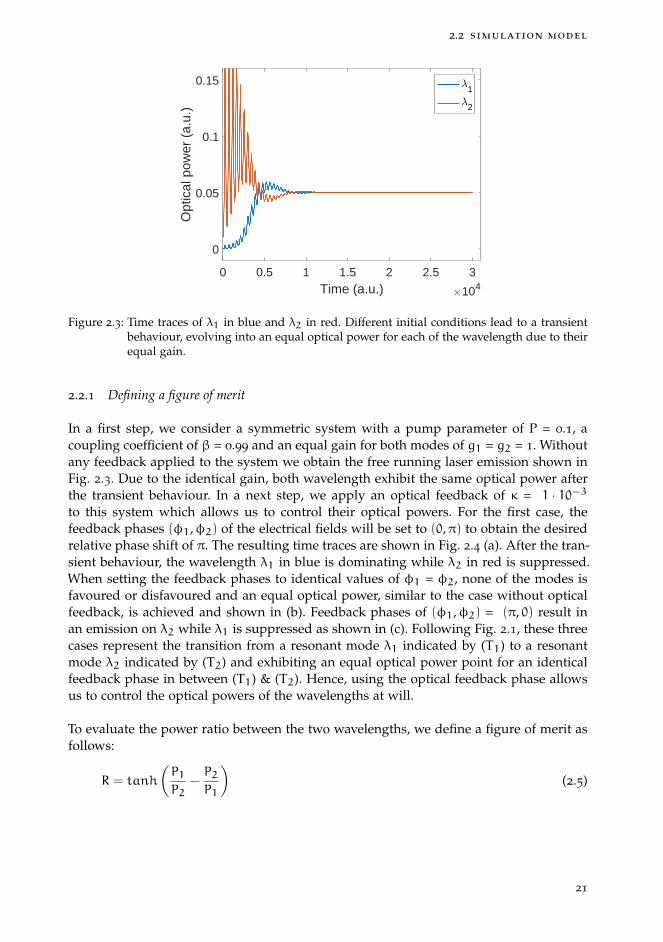
Figure 2.3: Time traces of λ1 in blue and λ2 in red. Different initial conditions lead to a transientbehaviour, evolving into an equal optical power for each of the wavelength due to theirequal gain.
2.2.1 Defining a figure of merit
In a first step, we consider a symmetric system with a pump parameter of P = 0.1, acoupling coefficient of β = 0.99 and an equal gain for both modes of g1 = g2 = 1. Withoutany feedback applied to the system we obtain the free running laser emission shown inFig. 2.3. Due to the identical gain, both wavelength exhibit the same optical power afterthe transient behaviour. In a next step, we apply an optical feedback of κ = 1 · 10−3to this system which allows us to control their optical powers. For the first case, thefeedback phases (φ1,φ2) of the electrical fields will be set to (0,π) to obtain the desiredrelative phase shift of π. The resulting time traces are shown in Fig. 2.4 (a). After the tran-sient behaviour, the wavelength λ1 in blue is dominating while λ2 in red is suppressed.When setting the feedback phases to identical values of φ1 = φ2, none of the modes isfavoured or disfavoured and an equal optical power, similar to the case without opticalfeedback, is achieved and shown in (b). Feedback phases of (φ1,φ2) = (π, 0) result inan emission on λ2 while λ1 is suppressed as shown in (c). Following Fig. 2.1, these threecases represent the transition from a resonant mode λ1 indicated by (T1) to a resonantmode λ2 indicated by (T2) and exhibiting an equal optical power point for an identicalfeedback phase in between (T1) & (T2). Hence, using the optical feedback phase allowsus to control the optical powers of the wavelengths at will.
To evaluate the power ratio between the two wavelengths, we define a figure of merit asfollows:
R = tanh
(P1P2
−P2P1
)(2.5)
21

control approach for dual-wavelength emission
0 1 2 3Time (a.u.) 104
0
0.05
0.1
0.15
Opt
ical
pow
er (
a.u.
)
1
2
(a)
0 1 2 3Time (a.u.) 104
0
0.05
0.1
0.15
Opt
ical
pow
er (
a.u.
)
1
2
(b)
0 1 2 3Time (a.u.) 104
0
0.05
0.1
0.15
Opt
ical
pow
er (
a.u.
)
1
2
(c)
0 1 2 3Time (a.u.) 104
-1
-0.5
0
0.5
1
R
(d)
0 1 2 3Time (a.u.) 104
-1
-0.5
0
0.5
1R
(e)
0 1 2 3Time (a.u.) 104
-1
-0.5
0
0.5
1
R
(f)
Figure 2.4: Temporal evolution for λ1 & λ2 for different feedback phases in (a) - (c). In (a), thephases have been set to (φ1,φ2) = (0,π), in (b) to identical phases of φ1 = φ2 and in (c)to (φ1,φ2) = (π, 0). In (d) - (f), the R values are plotted, quantifying the power ratiosbetween the wavelengths with values of -1 to +1, representing emission on λ2 and λ1,respectively, values of 0 represent equal optical powers.
with the optical powers P1 & P2 for the wavelengths λ1 & λ2, respectively. This approachallows us to specify the outcome of the simulation by one single parameter and simplifiesthe analysis in the following studies. The tanh allows for a figure of merit with valuesbetween +1 and -1, a +1 represents the sole emission on λ1 with λ2 suppressed, a valueof 0 corresponds to an equal emission on both wavelengths and a -1 represents the soleemission on λ2 while λ1 is suppressed. In Fig. 2.4 (d) - (f), the evolution of R has beencalculated for each case of (a) - (c), respectively. In (a), the emission starts on λ2 due to theinitial starting conditions and evolves towards a sole emission on λ1. This corresponds toan evolution from -1 to +1 in panel (d). For the equal phases in (b), an evolution from λ2to an equal power of both wavelengths is achieved, corresponding to a transition from-1 to 0 in panel (e). In (c), the emission on λ2 is persisting at all times, correspondingto a constant value of -1 in panel (f). Hence, R allows to evaluate the system behaviourby only one parameter. In the rest of this work, we will only consider the value of Rtaken when the system reaches a steady-state, i.e. we discard transient and dynamicalbehaviours.
22

2.3 phase dependency of switching performance
2.3 phase dependency of switching performance
To analyse the laser behaviour for all possible relative phase shifts, we vary the opticalfeedback phases φ1 & φ2 in a range from 0 to 2π. Taking the steady-state solutions ofR for each of the simulation outcome allows us to achieve mappings of the entire phasespace as shown in Fig. 2.5 (a) - (d). By varying specific parameters we can study theimpact on different relative phase shifts.
The first mapping Fig. 2.5 (a) represents an ideal set of parameters as a referencepoint. We assumed an identical gain of g1 = g2 = 1 together with a coupling coefficientof β = 0.99 and a feedback strength of κ = 3·10−4. This set of parameters leads to amapping with two dominant areas, the large blue and red region correspond to the soleemission of λ1 & λ2, respectively. The extreme cases for these two areas (φ1,φ2) = (0,π)for the blue region and (π, 0) for the red region, modulo 2π, correspond to the steadystate solutions in panel (a) & (c) of Fig. 2.4. The identical gain for both wavelengthsleads to this symmetrical case with equal power points along the lines of equal phasesφ1 = 2π±φ2 in green. An ideal coupling coefficient of β = 1 would lead to a completeredirection of the carriers to the favoured wavelength. The two areas would have valuesof either +1 or -1, with sharp edges separating them along the diagonal lines and withoutequal optical power points. However, as this is an behaviour unlikely to be observed inan experiment, we refrain from studying this extreme case. Starting from this referencepoint, we either reduced the coupling which lead to panel (b), or we reduced the gain ofone mode which lead to panel (c).
When reducing the coupling as shown in Fig. 2.5 (b), we observed a much smoothertransition between the wavelengths. For this, we assumed a value of β = 0.98 whichhampers the carrier redistribution and only leads to a partial switch with values of upto R = ±0.6.
When assuming different values of gain, one mode is expected to show a domi-nant behaviour and is shown in panel (c). We assumed gain values of g1 = 0.999 &g2 = 1, whereas the coupling coefficient and feedback strength was kept to β = 0.99 andκ = 3·10−4. As visible in panel (c), the blue region is much larger, i.e. λ1 is dominant forlarge range of relative phase shifts due to the higher gain. Only for a very small regionaround (φ1,φ2) = (π, 0), a partial switch up to a point of an equal power with R = 0.2is obtained.
In practice, a real laser source could possibly exhibit both effects at once. A loweredmode coupling could originate from limited carrier exchanges in the gain medium anddepending on the shape of the gain profile, the gain for each mode could be different.Therefore, both, the reduced coupling coefficient of β = 0.98 as well as the asymmetricgains of g1 = 0.999 & g2 = 1 are assumed in (d), combining the cases (b) and (c). Thetransitions between the different areas are very smooth and only a small modulation intheir power ratio of about R = ± 0.1 is achieved. Increasing the optical feedback strengthallows for a much better control, hence, we increased the optical feedback strength to avalue of κ = 9·10−4 to achieve the mapping shown in Fig. 2.6. This increase in feedbackstrength is sufficient to regain the full control over the laser emission and to achievea full switch between the wavelengths. Furthermore, the increase in feedback strengthreveals an asymmetry for the different areas. This could results in different slopes forthe transitions from (φ1,φ2) = (0,π) to (π, 2π) compared to the transition from (π, 0) to
23

control approach for dual-wavelength emission
2
0
2
-1
-0.5
0
0.5
1
0 2
1
2
0
2
0 2
1
-1
-0.5
0
0.5
1
(a) (b)
(c) (d)
R
R
Figure 2.5: Phase space with all possible relative feedback phases for λ1 & λ2. Blue and red re-gions correspond to the sole emission of λ1 and λ2, respectively, while green regionsrepresent equal optical powers. In (a), ideal conditions are assumed with equal gaing1 = g2 = 1 and a coupling coefficient of β = 0.99. In (b), only the coupling is reducedto β = 0.98 and g1 = g2 = 1, in (c) only the gain g1 = 0.999 with β = 0.99 and in (d),both, β = 0.98 and g1 = 0.999 are assumed.
24
2.3 phase dependency of switching performance
0 2
1
2
0
2
-1
-0.5
0
0.5
1
R
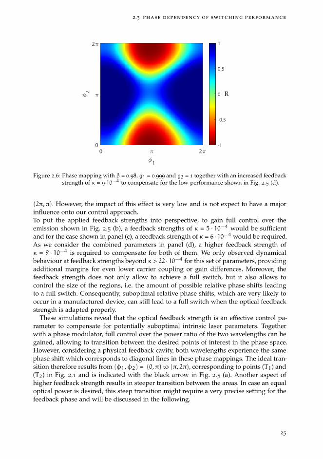
Figure 2.6: Phase mapping with β = 0.98, g1 = 0.999 and g2 = 1 together with an increased feedbackstrength of κ = 9·10−4 to compensate for the low performance shown in Fig. 2.5 (d).
(2π,π). However, the impact of this effect is very low and is not expect to have a majorinfluence onto our control approach.To put the applied feedback strengths into perspective, to gain full control over theemission shown in Fig. 2.5 (b), a feedback strengths of κ = 5 · 10−4 would be sufficientand for the case shown in panel (c), a feedback strength of κ = 6 · 10−4 would be required.As we consider the combined parameters in panel (d), a higher feedback strength ofκ = 9 · 10−4 is required to compensate for both of them. We only observed dynamicalbehaviour at feedback strengths beyond κ > 22 ·10−4 for this set of parameters, providingadditional margins for even lower carrier coupling or gain differences. Moreover, thefeedback strength does not only allow to achieve a full switch, but it also allows tocontrol the size of the regions, i.e. the amount of possible relative phase shifts leadingto a full switch. Consequently, suboptimal relative phase shifts, which are very likely tooccur in a manufactured device, can still lead to a full switch when the optical feedbackstrength is adapted properly.
These simulations reveal that the optical feedback strength is an effective control pa-rameter to compensate for potentially suboptimal intrinsic laser parameters. Togetherwith a phase modulator, full control over the power ratio of the two wavelengths can begained, allowing to transition between the desired points of interest in the phase space.However, considering a physical feedback cavity, both wavelengths experience the samephase shift which corresponds to diagonal lines in these phase mappings. The ideal tran-sition therefore results from (φ1,φ2) = (0,π) to (π, 2π), corresponding to points (T1) and(T2) in Fig. 2.1 and is indicated with the black arrow in Fig. 2.5 (a). Another aspect ofhigher feedback strength results in steeper transition between the areas. In case an equaloptical power is desired, this steep transition might require a very precise setting for thefeedback phase and will be discussed in the following.
25

control approach for dual-wavelength emission
0 /2Feedback phase
-1
-0.5
0
0.5
1R
(a)
0 /2Feedback phase
-1
-0.5
0
0.5
1
R
(b)
Increasing κ
Figure 2.7: Transition from (φ1,φ2) = (0,π) to (π, 2π), i.e. transitioning along the arrow in Fig.2.5 (a). Shown are solutions for different feedback strengths in the range of κ = 0 to 22 ·10−4 in steps of 2 · 10−4. The transition in (a) corresponds to the parameters used forFig. 2.5 (a) while (b) corresponds to the parameters used in for Fig. 2.5 (d). Partialswitches are achieved around κ ≈ 2.5 · 10−4 and full switches beyond κ ≈ 9·10−4.
2.3.1 Achieving a balanced optical power
In this section, we focus on achieving an equal optical power between the wavelengthsand study the dependency of the optical feedback strength under different parameters.For a detailed analysis, we reduce the phase space to the transition between the pointsof (φ1,φ2) = (0,π) and (π, 2π) along the arrow shown in Fig. 2.5 (a). This correspondsto an optimal transition induced by the phase modulator as desired in our experiments.
We study two sets of parameters to compare their impact on the capability of thesystem to reach an equal output power for the two wavelengths. First, we use the sameoperation point than already discussed for Fig. 2.5 (a) with β = 0.99 and g1 = g2 = 1 andvary the feedback strength in a range between κ = 0 to 22 · 10−4 in steps of 2 · 10−4. Withthis, we obtain the results shown in Fig. 2.7 (a). With the symmetrical gain consideredand no feedback applied, we expect an equal optical power between the modes andno influence of the feedback phase. This case corresponds to the horizontal blue line.Increasing the feedback strength to κ ≈ 2 · 10−4 allows for a partial switch and withfeedback strength beyond κ ≈ 3 · 10−4 a full control over the laser emission is achieved.However, as the laser will not exhibit this highly symmetrical behaviour in practice, weconsidered a second set of parameters with asymmetrical parameter settings. We usedthe same operation point already discussed for Fig. 2.5 (d) with a coupling coefficientof β = 0.98 and g1 = 0.999 & g2 = 1 together with the same variations in feedbackstrength of κ = 0 to 22 · 10−4 to obtain the results shown in Fig. 2.7 (b). Without opticalfeedback applied, the emission is in favour of λ2 with values of R ≈ -0.5, representedby the horizontal blue line and is a result from the asymmetric gain of the wavelengths.With increasing feedback strength, an equal optical power can be achieved with feedbackstrength around κ ≈ 2.5 · 10−4 at a feedback delay of π. To gain full control over the
26
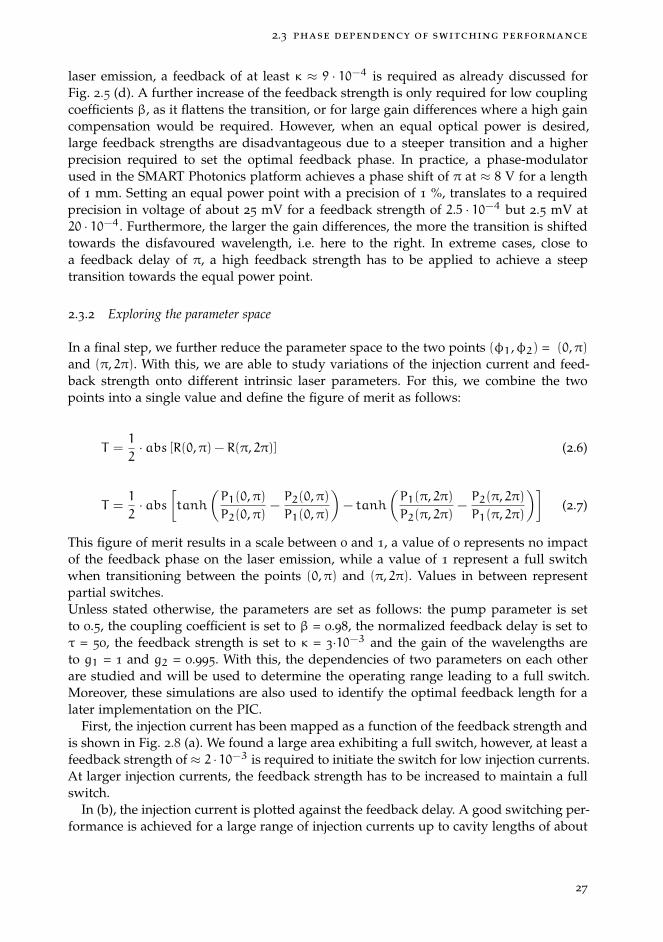
2.3 phase dependency of switching performance
laser emission, a feedback of at least κ ≈ 9 · 10−4 is required as already discussed forFig. 2.5 (d). A further increase of the feedback strength is only required for low couplingcoefficients β, as it flattens the transition, or for large gain differences where a high gaincompensation would be required. However, when an equal optical power is desired,large feedback strengths are disadvantageous due to a steeper transition and a higherprecision required to set the optimal feedback phase. In practice, a phase-modulatorused in the SMART Photonics platform achieves a phase shift of π at ≈ 8 V for a lengthof 1 mm. Setting an equal power point with a precision of 1 %, translates to a requiredprecision in voltage of about 25 mV for a feedback strength of 2.5 · 10−4 but 2.5 mV at20 · 10−4. Furthermore, the larger the gain differences, the more the transition is shiftedtowards the disfavoured wavelength, i.e. here to the right. In extreme cases, close toa feedback delay of π, a high feedback strength has to be applied to achieve a steeptransition towards the equal power point.
2.3.2 Exploring the parameter space
In a final step, we further reduce the parameter space to the two points (φ1,φ2) = (0,π)and (π, 2π). With this, we are able to study variations of the injection current and feed-back strength onto different intrinsic laser parameters. For this, we combine the twopoints into a single value and define the figure of merit as follows:
T =1
2· abs [R(0,π) − R(π, 2π)] (2.6)
T =1
2· abs
[tanh
(P1(0,π)P2(0,π)
−P2(0,π)P1(0,π)
)− tanh
(P1(π, 2π)P2(π, 2π)
−P2(π, 2π)P1(π, 2π)
)](2.7)
This figure of merit results in a scale between 0 and 1, a value of 0 represents no impactof the feedback phase on the laser emission, while a value of 1 represent a full switchwhen transitioning between the points (0,π) and (π, 2π). Values in between representpartial switches.Unless stated otherwise, the parameters are set as follows: the pump parameter is setto 0.5, the coupling coefficient is set to β = 0.98, the normalized feedback delay is set toτ = 50, the feedback strength is set to κ = 3·10−3 and the gain of the wavelengths areto g1 = 1 and g2 = 0.995. With this, the dependencies of two parameters on each otherare studied and will be used to determine the operating range leading to a full switch.Moreover, these simulations are also used to identify the optimal feedback length for alater implementation on the PIC.
First, the injection current has been mapped as a function of the feedback strength andis shown in Fig. 2.8 (a). We found a large area exhibiting a full switch, however, at least afeedback strength of ≈ 2 · 10−3 is required to initiate the switch for low injection currents.At larger injection currents, the feedback strength has to be increased to maintain a fullswitch.
In (b), the injection current is plotted against the feedback delay. A good switching per-formance is achieved for a large range of injection currents up to cavity lengths of about
27
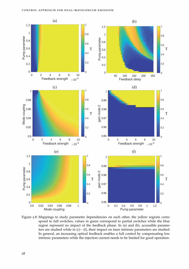
control approach for dual-wavelength emission
0 2 4 6 8 10Feedback strength 10-3
0
0.2
0.4
0.6
0.8
1
1.2P
um
p p
ara
me
ter
0
0.2
0.4
0.6
0.8
1(a)
T
50 100 150 200 250Feedback delay
0
0.2
0.4
0.6
0.8
1
1.2
Pu
mp
pa
ram
ete
r
0
0.2
0.4
0.6
0.8
1
(b)
T
0 2 4 6 8 10Feedback strength 10-3
0.9
0.92
0.94
0.96
0.98
1
Mo
de
co
up
ling
0
0.2
0.4
0.6
0.8
1(c)
T
0 2 4 6 8 10Feedback strength 10-3
0.95
0.96
0.97
0.98
0.99
1
ga
in m
od
e 2
0
0.2
0.4
0.6
0.8
1(d)
T
0.9 0.92 0.94 0.96 0.98 1Mode coupling
0
0.2
0.4
0.6
0.8
1
1.2
Pu
mp
pa
ram
ete
r
0
0.2
0.4
0.6
0.8
1
(e)
T
Pump parameter
0.95
0.96
0.97
0.98
0.99
1
ga
in m
od
e 2
0
0.2
0.4
0.6
0.8
1
1.210.80.60.40.20
(f)
T
Figure 2.8: Mappings to study parameter dependencies on each other, the yellow regions corre-spond to full switches, values in green correspond to partial switches while the blueregion represent no impact of the feedback phase. In (a) and (b), accessible parame-ters are studied while in (c) - (f), their impact on laser intrinsic parameters are studied.In general, an increasing optical feedback enables a full control by compensating lowintrinsic parameters while the injection current needs to be limited for good operation.
28
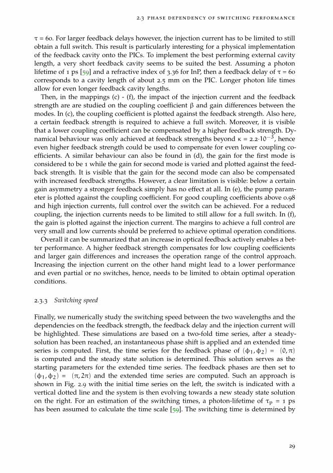
2.3 phase dependency of switching performance
τ = 60. For larger feedback delays however, the injection current has to be limited to stillobtain a full switch. This result is particularly interesting for a physical implementationof the feedback cavity onto the PICs. To implement the best performing external cavitylength, a very short feedback cavity seems to be suited the best. Assuming a photonlifetime of 1 ps [59] and a refractive index of 3.36 for InP, then a feedback delay of τ = 60
corresponds to a cavity length of about 2.5 mm on the PIC. Longer photon life timesallow for even longer feedback cavity lengths.
Then, in the mappings (c) - (f), the impact of the injection current and the feedbackstrength are are studied on the coupling coefficient β and gain differences between themodes. In (c), the coupling coefficient is plotted against the feedback strength. Also here,a certain feedback strength is required to achieve a full switch. Moreover, it is visiblethat a lower coupling coefficient can be compensated by a higher feedback strength. Dy-namical behaviour was only achieved at feedback strengths beyond κ = 2.2·10−3, henceeven higher feedback strength could be used to compensate for even lower coupling co-efficients. A similar behaviour can also be found in (d), the gain for the first mode isconsidered to be 1 while the gain for second mode is varied and plotted against the feed-back strength. It is visible that the gain for the second mode can also be compensatedwith increased feedback strengths. However, a clear limitation is visible: below a certaingain asymmetry a stronger feedback simply has no effect at all. In (e), the pump param-eter is plotted against the coupling coefficient. For good coupling coefficients above 0.98
and high injection currents, full control over the switch can be achieved. For a reducedcoupling, the injection currents needs to be limited to still allow for a full switch. In (f),the gain is plotted against the injection current. The margins to achieve a full control arevery small and low currents should be preferred to achieve optimal operation conditions.
Overall it can be summarized that an increase in optical feedback actively enables a bet-ter performance. A higher feedback strength compensates for low coupling coefficientsand larger gain differences and increases the operation range of the control approach.Increasing the injection current on the other hand might lead to a lower performanceand even partial or no switches, hence, needs to be limited to obtain optimal operationconditions.
2.3.3 Switching speed
Finally, we numerically study the switching speed between the two wavelengths and thedependencies on the feedback strength, the feedback delay and the injection current willbe highlighted. These simulations are based on a two-fold time series, after a steady-solution has been reached, an instantaneous phase shift is applied and an extended timeseries is computed. First, the time series for the feedback phase of (φ1,φ2) = (0,π)is computed and the steady state solution is determined. This solution serves as thestarting parameters for the extended time series. The feedback phases are then set to(φ1,φ2) = (π, 2π) and the extended time series are computed. Such an approach isshown in Fig. 2.9 with the initial time series on the left, the switch is indicated with avertical dotted line and the system is then evolving towards a new steady state solutionon the right. For an estimation of the switching times, a photon-lifetime of τp = 1 pshas been assumed to calculate the time scale [59]. The switching time is determined by
29
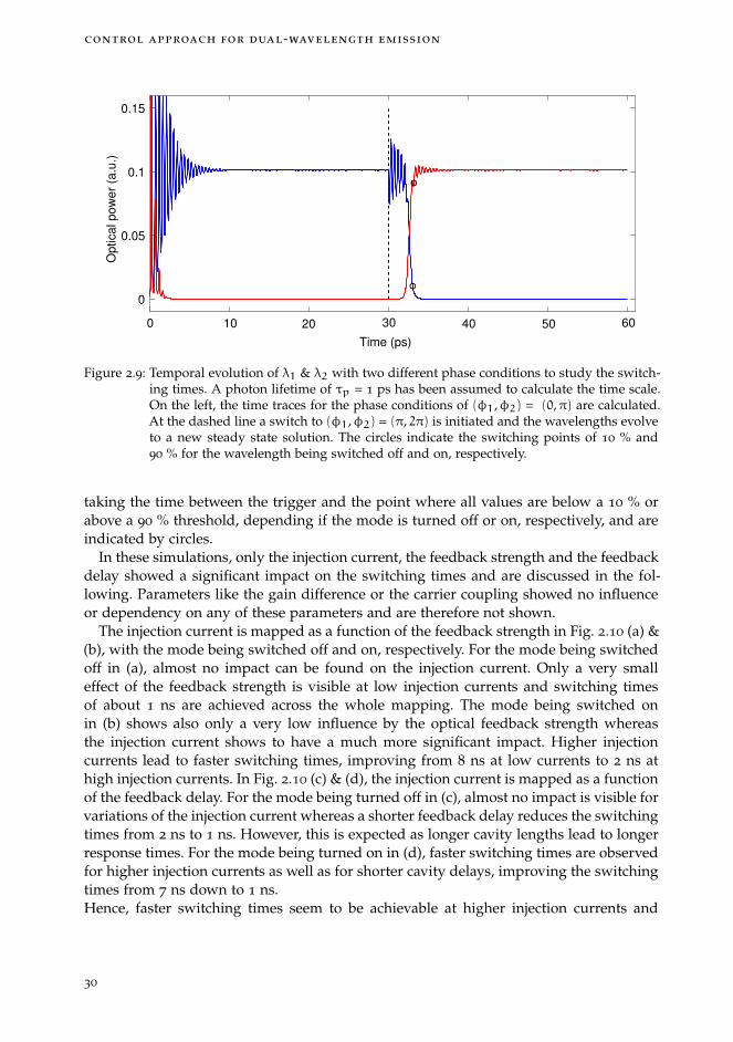
control approach for dual-wavelength emission
Time (ps)
0
0.05
0.1
0.15O
ptica
l p
ow
er
(a.u
.)
0 10 20 30 40 50 60
Figure 2.9: Temporal evolution of λ1 & λ2 with two different phase conditions to study the switch-ing times. A photon lifetime of τp = 1 ps has been assumed to calculate the time scale.On the left, the time traces for the phase conditions of (φ1,φ2) = (0,π) are calculated.At the dashed line a switch to (φ1,φ2) = (π, 2π) is initiated and the wavelengths evolveto a new steady state solution. The circles indicate the switching points of 10 % and90 % for the wavelength being switched off and on, respectively.
taking the time between the trigger and the point where all values are below a 10 % orabove a 90 % threshold, depending if the mode is turned off or on, respectively, and areindicated by circles.
In these simulations, only the injection current, the feedback strength and the feedbackdelay showed a significant impact on the switching times and are discussed in the fol-lowing. Parameters like the gain difference or the carrier coupling showed no influenceor dependency on any of these parameters and are therefore not shown.
The injection current is mapped as a function of the feedback strength in Fig. 2.10 (a) &(b), with the mode being switched off and on, respectively. For the mode being switchedoff in (a), almost no impact can be found on the injection current. Only a very smalleffect of the feedback strength is visible at low injection currents and switching timesof about 1 ns are achieved across the whole mapping. The mode being switched onin (b) shows also only a very low influence by the optical feedback strength whereasthe injection current shows to have a much more significant impact. Higher injectioncurrents lead to faster switching times, improving from 8 ns at low currents to 2 ns athigh injection currents. In Fig. 2.10 (c) & (d), the injection current is mapped as a functionof the feedback delay. For the mode being turned off in (c), almost no impact is visible forvariations of the injection current whereas a shorter feedback delay reduces the switchingtimes from 2 ns to 1 ns. However, this is expected as longer cavity lengths lead to longerresponse times. For the mode being turned on in (d), faster switching times are observedfor higher injection currents as well as for shorter cavity delays, improving the switchingtimes from 7 ns down to 1 ns.Hence, faster switching times seem to be achievable at higher injection currents and
30
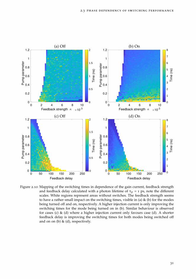
2.3 phase dependency of switching performance
0 2 4 6 8 10
Feedback strength 10-3
1.2
1
0.8
0.6
0.4
0.2
0
Pu
mp
pa
ram
ete
r
0
0.5
1
1.5
2
0 2 4 6 8 10
Feedback strength 10-3
1.2
1
0.8
0.6
0.4
0.2
0 0
1
2
3
4
5
6
7
8
50 100 150 200 250
Feedback delay
1.2
1
0.8
0.6
0.4
0.2
0 0
0.5
1
1.5
2
0
1.2
1
0.8
0.6
0.4
0.2
050 100 150 200 250
Feedback delay
0 0
1
2
3
4
5
6
7
8
Pu
mp
pa
ram
ete
rP
um
p p
ara
me
ter
Pu
mp
pa
ram
ete
r
Tim
e (
ns)
Tim
e (
ns)
Tim
e (
ns)
Tim
e (
ns)
(a) Off (b) On
(c) Off (d) On
Figure 2.10: Mapping of the switching times in dependence of the gain current, feedback strengthand feedback delay calculated with a photon lifetime of τp = 1 ps, note the differentscales. White regions represent areas without switches. The feedback strength seemsto have a rather small impact on the switching times, visible in (a) & (b) for the modesbeing turned off and on, respectively. A higher injection current is only improving theswitching times for the mode being turned on in (b). Similar behaviour is observedfor cases (c) & (d) where a higher injection current only favours case (d). A shorterfeedback delay is improving the switching times for both modes being switched offand on on (b) & (d), respectively.
31

control approach for dual-wavelength emission
shorter feedback delays, whereas the feedback strength does not seem to be a crucialparameter. We have seen that the feedback strength allows to gain a full control over thelaser emission in previous sections. Finding a low influence of the feedback strength onthe switching times is particularly interesting as it allows to achieve a full laser controlwithout influencing the switching times. To put the switching times into perspective,other simulations performed on dual-wavelength switching have been conducted in [55],[62], [64] and [65] and have been discussed for in Fig. 1.5 (b) & (c). Their simulations arebased the same model and switching times of down to 1 ns have been obtained. However,the major difference in their approach is the use of SOAs to induce a switch, hence, ahigher feedback strength leads to better switching times. Experimental switching timesof 31 ns have been reported in [62] with a wavelength transition time of 5 ns. Hence, ourapproach could lead to significantly faster switching times than other solutions.
32
2.4 conclusion
2.4 conclusion
To conclude this chapter, we first proposed a novel control approach based on a phasesensitive optical feedback loop to control the power ratio between two modes. First,we introduced a simulation model to determine and study the most crucial parametersleading to the best performances. We mapped all possible relative phase shifts betweenthe two wavelengths and found large regions exhibiting a full switch. Using the opti-cal feedback strength as an active control allowed us to obtain a full switch even forsuboptimal relative phase shifts. This finding might be crucial in case manufacturingtolerances lead to slight deviations in the spectral separation, i.e. to an imperfect relativephase shift, which could impede the control approach. We then focused on achieving anequal optical power between the wavelengths by using the feedback strength as a controlmechanism. We found that increasing the feedback strength allows to compensate largegain differences and low carrier couplings. However, these increased feedback strengthsrequire a precise setting of the feedback phase to obtain an equal optical power. In a laststep we focused on exploring the parameter space to find good laser operation pointswhich can be used as indicators for later experimental work. Moreover, we also found anoptimal parameter region for the implementation of feedback cavity on the PIC. We iden-tified two major points: first, a larger feedback strength enables a better control whereasthe injection current has to be limited to obtain a better switching performance. This isa good indicator when aiming for a full emission control in a later experiment. Second,we found a shorter feedback cavity to be beneficial for the best switching performanceas well as fastest switching times.
In the next chapter, we will discuss the design and optimization process of our dual-wavelength lasers. The goal is to determine the exact emitting wavelengths already inthe design stage to implement corresponding feedback cavities to achieve the optimalrelative phase shift of π in chapter 4.
33

3 I N T E G R AT E D D U A L - WAV E L E N G T H L A S E R S
In this chapter, we design different dual-wavelength lasers, that will then be used later on,to demonstrate our control approach. Four different laser concepts, capable of emittingsimultaneously on two different wavelengths, will be presented. We aim to determine theprecise emitting wavelengths of our lasers by simulations to implement correspondingoptical feedback-sections in a next step as will be discussed in chapter 4. We use acircuit simulator as an optimisation tool, but also to determine the precise wavelengthseach laser will emit on. These wavelengths are then basis for the implementation ofcorresponding optical feedback-sections in chapter 4. In the first section 3.1, the differentdual-wavelength laser concepts will be presented and the characteristics and limitationsof each concept will be discussed. In the second section 3.2, the experimental results of afirst MPW participation will be presented and are the basis for the optimisation processof each laser discussed in section 3.3 which were then implemented onto a second MWPrun. The experimental setup and practical aspects of operating the PIC will be discussedin section 3.4. Their characterisation will be presented in section 3.5, together with theimpact a change in current or temperature has on the DBR structures.
35
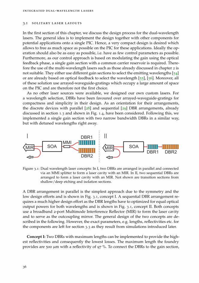
integrated dual-wavelength lasers
3.1 solitary laser layouts
In the first section of this chapter, we discuss the design process for the dual-wavelengthlasers. The general idea is to implement the design together with other components forpotential applications onto a single PIC. Hence, a very compact design is desired whichallows to free as much space as possible on the PIC for these applications. Ideally the op-eration should also be as easy as possible, i.e. have as few control parameters as possible.Furthermore, as our control approach is based on modulating the gain using the opticalfeedback phase, a single gain section with a common carrier reservoir is required. There-fore the use of the multi-wavelength lasers such as those already discussed in chapter 2 isnot suitable. They either use different gain sections to select the emitting wavelengths [54]or are already based on optical feedback to select the wavelength [55], [56]. Moreover, allof these solution use arrayed-waveguide-gratings which occupy a large amount of spaceon the PIC and are therefore not the first choice.
As no other laser sources were available, we designed our own custom lasers. Fora wavelength selection, DBRs have been favoured over arrayed-waveguide-gratings forcompactness and simplicity in their design. As an orientation for their arrangements,the discrete devices with parallel [28] and sequential [29] DBR arrangements, alreadydiscussed in section 1.3 and shown in Fig. 1.4, have been considered. Following this, weimplemented a single gain section with two narrow bandwidth DBRs in a similar way,but with detuned wavelengths right away.
DBR1
DBR2
MMI
MIR SOA SOA
DBR1 DBR2MIR
I II
Figure 3.1: Dual wavelength laser concepts: In I, two DBRs are arranged in parallel and connectedvia an MMI splitter to form a laser cavity with an MIR. In II, two sequential DBRs arearranged to form a laser cavity with an MIR. Not shown are transition sections fromshallow/deep etching and isolation sections.
A DBR arrangement in parallel is the simplest approach due to the symmetry and thelow design efforts and is shown in Fig. 3.1, concept I. A sequential DBR arrangement re-quires a much higher design effort as the DBR lengths have to optimized for equal opticaloutput powers for both wavelengths and is shown in Fig. 3.1, concept II. Both conceptsuse a broadband 2-port Multimode Interference Reflector (MIR) to form the laser cavityand to serve as the outcoupling mirror. The general design of the two concepts are de-scribed in the following. However, the exact parameters, e.g. lengths, reflectivities etc. forthe components are left for section 3.3 as they result from simulations introduced later.
Concept I: Two DBRs with maximum lengths can be implemented to provide the high-est reflectivities and consequently the lowest losses. The maximum length the foundryprovides are 500 µm with a reflectivity of 97 %. To connect the DBRs to the gain section,
36

3.1 solitary laser layouts
bend waveguides are used to connect them via an MMI splitter to the SOA. Anotherwaveguide then connects the SOA to one port of the MIR with a reflectivity of ≈ 50 %to form the laser cavity. The second port is used to couple light out of the laser. Thisapproach results in a long laser cavity as the DBRs need to be spatially separated formanufacturing. The bending radius for the waveguides connecting the DBRs to the MMIsplitter is however limited, hence, long waveguides have to be implemented. However,a long cavity results in a small longitudinal mode separation which can lead to a multi-mode emission if the reflection bandwidth of the DBR is too large. Hence, the selectivityof the DBRs need to be sufficiently high to select individual modes. As the couplingcoefficient for the DBRs is fixed by the foundry, the DBR lengths have to be reducedto improve their selectivity. Shorter DBRs have a curved top instead of a flat top whichincreases the wavelength dependency. However, this would increase the losses and hastherefore been avoided. Instead, the longitudinal mode separation has been improved byminimizing the cavity length. For that, deeply etched waveguides with small bendingradii have been used to achieve the shortest cavity length possible. To avoid transitionsections between different etching depths, as they increases the cavity length and alsoadd additional losses, every component should ideally be implemented deeply etched toachieve the most compact design. However, SOAs are only available in shallow etchingwhich makes transition sections unavoidable. This result in a trade-off between maximalcompactness to achieve a large longitudinal wavelength separation and a longer cavitylength with less components and lower losses but a smaller wavelength separation. As adual-wavelength emission on two single modes is crucial, the compactness of the designis favoured. Hence, every component has been implemented in deep etching, except theSOA which required two transition sections on either side. Furthermore, mode-filtersto avoid emission on higher order transversal modes have not been included to reducethe cavity length. Nevertheless, a major drawback of this approach is the transparencyof the DBRs at each others wavelength. This results in optical output at three differentpoints and in undesired losses. To overcome this issue, the laser cavity should not betransparent and consequently suggests a sequential arrangement of the DBRs. This way,the transmitted light by one DBR is confined to the laser cavity by the second DBR aswill be discussed in the following.
Concept II: For this concept, two DBRs are arranged sequentially to improve outputpower, reduce the cavity length and subsequently increase the longitudinal wavelengthseparation. However, these benefits come with a much higher design effort to optimizethe DBRs for an equal optical output power for both wavelengths. The sequential DBRarrangement avoids the mutual transparencies of the DBRs, therefore results in reducedlosses which consequently lowers the laser threshold and improves the optical outputpower. To minimize losses, the DBR lengths should be as long as possible to providehighest reflectivities. However, this leads to a very long cavity length formed by DBR2and could potentially lead to a multi-mode emission. Hence, also for this concept, atrade-off between high reflectivities for low losses and short DBRs for high selectivitiesand single-mode emission has to be considered. Moreover, this consideration also has toinclude the correct lengths for an equal output power of both wavelengths. To find thebest set of parameters, simulations will be used in section 3.3. For this layout, no MMIsplitter or s-bend waveguides are required, allowing for the implementation of the DBRs
37
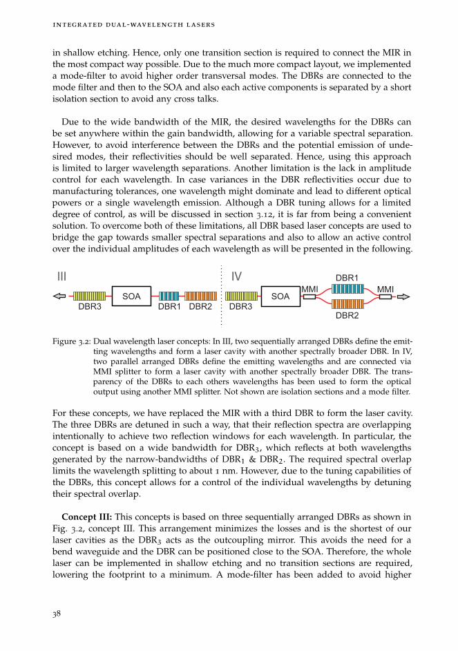
integrated dual-wavelength lasers
in shallow etching. Hence, only one transition section is required to connect the MIR inthe most compact way possible. Due to the much more compact layout, we implementeda mode-filter to avoid higher order transversal modes. The DBRs are connected to themode filter and then to the SOA and also each active components is separated by a shortisolation section to avoid any cross talks.
Due to the wide bandwidth of the MIR, the desired wavelengths for the DBRs canbe set anywhere within the gain bandwidth, allowing for a variable spectral separation.However, to avoid interference between the DBRs and the potential emission of unde-sired modes, their reflectivities should be well separated. Hence, using this approachis limited to larger wavelength separations. Another limitation is the lack in amplitudecontrol for each wavelength. In case variances in the DBR reflectivities occur due tomanufacturing tolerances, one wavelength might dominate and lead to different opticalpowers or a single wavelength emission. Although a DBR tuning allows for a limiteddegree of control, as will be discussed in section 3.12, it is far from being a convenientsolution. To overcome both of these limitations, all DBR based laser concepts are used tobridge the gap towards smaller spectral separations and also to allow an active controlover the individual amplitudes of each wavelength as will be presented in the following.
DBR1 DBR2DBR3
DBR1
DBR2
DBR3
MMI MMISOA
III IV
SOA
Figure 3.2: Dual wavelength laser concepts: In III, two sequentially arranged DBRs define the emit-ting wavelengths and form a laser cavity with another spectrally broader DBR. In IV,two parallel arranged DBRs define the emitting wavelengths and are connected viaMMI splitter to form a laser cavity with another spectrally broader DBR. The trans-parency of the DBRs to each others wavelengths has been used to form the opticaloutput using another MMI splitter. Not shown are isolation sections and a mode filter.
For these concepts, we have replaced the MIR with a third DBR to form the laser cavity.The three DBRs are detuned in such a way, that their reflection spectra are overlappingintentionally to achieve two reflection windows for each wavelength. In particular, theconcept is based on a wide bandwidth for DBR3, which reflects at both wavelengthsgenerated by the narrow-bandwidths of DBR1 & DBR2. The required spectral overlaplimits the wavelength splitting to about 1 nm. However, due to the tuning capabilities ofthe DBRs, this concept allows for a control of the individual wavelengths by detuningtheir spectral overlap.
Concept III: This concepts is based on three sequentially arranged DBRs as shown inFig. 3.2, concept III. This arrangement minimizes the losses and is the shortest of ourlaser cavities as the DBR3 acts as the outcoupling mirror. This avoids the need for abend waveguide and the DBR can be positioned close to the SOA. Therefore, the wholelaser can be implemented in shallow etching and no transition sections are required,lowering the footprint to a minimum. A mode-filter has been added to avoid higher
38

3.1 solitary laser layouts
order transversal modes and isolation sections have been implemented between eachactive component.
Concept IV: Although we identified the parallel laser arrangement to have higherlosses due to their transparency to each other, we aimed to exploit this peculiarity inthis concept. We therefore combined the outputs of DBR1 & DBR2 via an MMI andmerged their beams to serve as an optical output to improve the optical output power asshown in Fig. 3.2, concept IV. For compactness of the laser cavity, deep etching has beenused for both MMIs and DBR1 & DBR2. This approach is not directly comparable to theother laser concepts as the transparency of the DBRs to each other also allows the opticalfeedback to easily enter the laser cavity. This approach therefore represents an ambitiousattempt to achieve controllable dual-wavelength laser with a maximum output powerfor a wavelength separation around 1 nm.
39
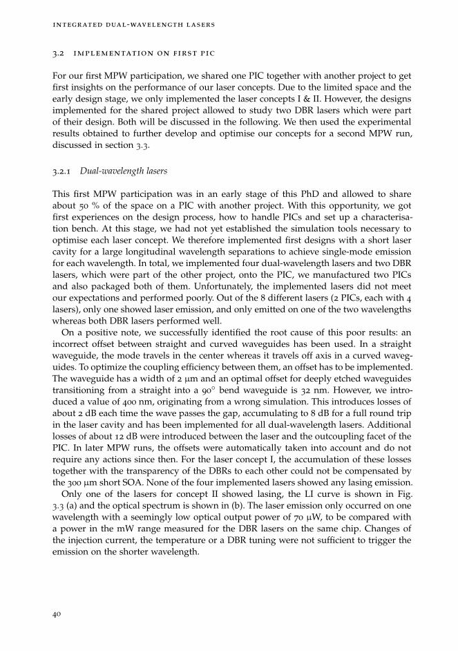
integrated dual-wavelength lasers
3.2 implementation on first pic
For our first MPW participation, we shared one PIC together with another project to getfirst insights on the performance of our laser concepts. Due to the limited space and theearly design stage, we only implemented the laser concepts I & II. However, the designsimplemented for the shared project allowed to study two DBR lasers which were partof their design. Both will be discussed in the following. We then used the experimentalresults obtained to further develop and optimise our concepts for a second MPW run,discussed in section 3.3.
3.2.1 Dual-wavelength lasers
This first MPW participation was in an early stage of this PhD and allowed to shareabout 50 % of the space on a PIC with another project. With this opportunity, we gotfirst experiences on the design process, how to handle PICs and set up a characterisa-tion bench. At this stage, we had not yet established the simulation tools necessary tooptimise each laser concept. We therefore implemented first designs with a short lasercavity for a large longitudinal wavelength separations to achieve single-mode emissionfor each wavelength. In total, we implemented four dual-wavelength lasers and two DBRlasers, which were part of the other project, onto the PIC, we manufactured two PICsand also packaged both of them. Unfortunately, the implemented lasers did not meetour expectations and performed poorly. Out of the 8 different lasers (2 PICs, each with 4
lasers), only one showed laser emission, and only emitted on one of the two wavelengthswhereas both DBR lasers performed well.
On a positive note, we successfully identified the root cause of this poor results: anincorrect offset between straight and curved waveguides has been used. In a straightwaveguide, the mode travels in the center whereas it travels off axis in a curved waveg-uides. To optimize the coupling efficiency between them, an offset has to be implemented.The waveguide has a width of 2 µm and an optimal offset for deeply etched waveguidestransitioning from a straight into a 90
◦ bend waveguide is 32 nm. However, we intro-duced a value of 400 nm, originating from a wrong simulation. This introduces losses ofabout 2 dB each time the wave passes the gap, accumulating to 8 dB for a full round tripin the laser cavity and has been implemented for all dual-wavelength lasers. Additionallosses of about 12 dB were introduced between the laser and the outcoupling facet of thePIC. In later MPW runs, the offsets were automatically taken into account and do notrequire any actions since then. For the laser concept I, the accumulation of these lossestogether with the transparency of the DBRs to each other could not be compensated bythe 300 µm short SOA. None of the four implemented lasers showed any lasing emission.
Only one of the lasers for concept II showed lasing, the LI curve is shown in Fig.3.3 (a) and the optical spectrum is shown in (b). The laser emission only occurred on onewavelength with a seemingly low optical output power of 70 µW, to be compared witha power in the mW range measured for the DBR lasers on the same chip. Changes ofthe injection current, the temperature or a DBR tuning were not sufficient to trigger theemission on the shorter wavelength.
40

3.2 implementation on first pic
1540 1541 1542 1551 1552 1553
Wavelength (nm)
-60
-40
-20
0
Op
t. p
ow
er
(dB
m)
15 20 25 30 35 40
Current (mA)
0
0.02
0.04
0.06
0.08O
pt. p
ow
er
(mW
)
Figure 3.3: LI curve of the laser concept II for first PIC generation. Optical spectrum for the laserconcept II at a gain current of 36 mA, emission could only be achieved at the longerwavelengths with a single mode emission at 1551.8 nm and a SMSR of about 45 dB. Thelower wavelength could not be triggered by any means.
The origin for this is not clear, however, two possible issues could be identified: highlosses due to the wrongly implemented offsets or unbalanced DBRs. For this laser, DBRlengths of DBR1 = 200µm and DBR2 = 370µm have been implemented with wavelengthsof 1540 nm & 1550 nm, respectively. Possibly a shortening of DBR1 or an increase ofthe DBR2 length could lead to simultaneous dual-wavelength emission. To improve ourdesigns and overcome this issue, we will perform simulation work for the second gener-ation of dual-wavelength lasers to optimize the DBR lengths in section 3.3.
3.2.2 Single-wavelength DBR laser
DBR1 DBR2
SOA
Figure 3.4: Schematic of DBR laser, implemented with two different SOA lengths of 500 µm and1500 µm with identical central DBR wavelength for each laser individually.
Studying the DBR lasers allowed us to have a reference point in terms of optical outputpower and spectral tuning capabilities for our dual-wavelength lasers. The DBR laserconsists of a SOA section and two spectrally identical DBRs illustrated in Fig. 3.4. TheDBR lasers have an SOA lengths of 500 µm and 1500 µm and have been implementedwith the parameters detailed in Tab. 3.1. DBR1 on the left, serves as a highly reflectivemirror, while the DBR1 on the right was kept short to serve as an outcoupling mirror.We expected single mode emission for the shorter DBR laser and multi-mode emissionfor the longer DBR laser due to its long laser cavity.The LI curve for the 500 µm long DBR laser without any DBR currents applied is shownin Fig. 3.5 (a) and exhibits a maximum optical output power of 2.2 mW at 100 mA. The
41
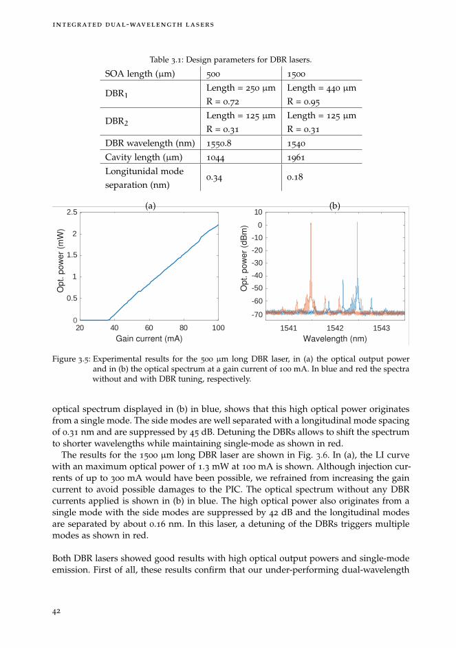
integrated dual-wavelength lasers
Table 3.1: Design parameters for DBR lasers.
SOA length (µm) 500 1500
DBR1Length = 250 µmR = 0.72
Length = 440 µmR = 0.95
DBR2Length = 125 µmR = 0.31
Length = 125 µmR = 0.31
DBR wavelength (nm) 1550.8 1540
Cavity length (µm) 1044 1961
Longitunidal modeseparation (nm)
0.34 0.18
20 40 60 80 100
Gain current (mA)
0
0.5
1
1.5
2
2.5
Op
t. p
ow
er
(mW
)
1541 1542 1543Wavelength (nm)
-70
-60
-50
-40
-30
-20
-10
0
10
Op
t. p
ow
er
(dB
m)
(a) (b)
Figure 3.5: Experimental results for the 500 µm long DBR laser, in (a) the optical output powerand in (b) the optical spectrum at a gain current of 100 mA. In blue and red the spectrawithout and with DBR tuning, respectively.
optical spectrum displayed in (b) in blue, shows that this high optical power originatesfrom a single mode. The side modes are well separated with a longitudinal mode spacingof 0.31 nm and are suppressed by 45 dB. Detuning the DBRs allows to shift the spectrumto shorter wavelengths while maintaining single-mode as shown in red.
The results for the 1500 µm long DBR laser are shown in Fig. 3.6. In (a), the LI curvewith an maximum optical power of 1.3 mW at 100 mA is shown. Although injection cur-rents of up to 300 mA would have been possible, we refrained from increasing the gaincurrent to avoid possible damages to the PIC. The optical spectrum without any DBRcurrents applied is shown in (b) in blue. The high optical power also originates from asingle mode with the side modes are suppressed by 42 dB and the longitudinal modesare separated by about 0.16 nm. In this laser, a detuning of the DBRs triggers multiplemodes as shown in red.
Both DBR lasers showed good results with high optical output powers and single-modeemission. First of all, these results confirm that our under-performing dual-wavelength
42

3.2 implementation on first pic
40 60 80 100
Gain current (mA)
0
0.2
0.4
0.6
0.8
1
1.2
1.4
Op
t. p
ow
er
(mW
)
1550 1551 1552 1553Wavelength (nm)
-60
-50
-40
-30
-20
-10
0
10
Op
t. p
ow
er
(dB
m)
(a) (b)
Figure 3.6: Experimental results for the 1500 µm long DBR laser, in (a) the optical output powerand in (b) the optical spectrum at a gain current of 100 mA. In blue and red the spectrawithout and with DBR tuning, respectively.(Lowered spectral resolution of the OSA of0.02 nm.)
lasers are in fact the result of a failure in our implementation process. This is evidentwhen comparing the optical power levels of both DBR lasers with up to 2.2 mW tothe dual-wavelength laser layout II, only emitting with 0.07 mW. Clearly high lossesare the origin of this limited performance. Following these results, we implemented500 µm long SOAs in our next generation of dual-wavelength lasers. The lengths of ourdual-wavelength laser cavities are in the same range than the ones of the 500 µm longDBR laser, hence, single-mode emission with a high optical output powers can also beexpected for our laser concepts.
43

integrated dual-wavelength lasers
3.3 optimization of dual-wavelength concepts
With the insights gained from our first MPW run, we aimed to improve each laser con-cept for a second MPW participation. In this section, we determine the ideal DBR param-eters to ensure the best performance as well as to determine the expected wavelengthdifferences the lasers will emit on. These wavelengths will then be the starting point todesign customized optical feedback cavities for each laser concept in chapter 4. Withthe results obtained from the DBR lasers, we fixed the SOA lengths of all laser con-cepts to 500 µm. In a next step, the DBR lengths will be determined using the circuitsolver Lumerical Interconnect. The software solution provides a set of building blockswhich can be adapted to the specific platform used. At the development stage of the soft-ware, no dedicated library for the foundry platform was available. We therefore adaptedeach component in compliance with the foundry manual to achieve the best startingconditions possible. The foundry provided refractive indices, dimensions of waveguides,mirror reflectivities as well as the coupling coefficient for the DBRs. For the gain curve,no experimental data could be implemented, we therefore used a standard Lorentzianline shape to model it. An example of an implementation into the simulator is shown inFig. 3.7 and represents the laser concept I, shown in Fig. 3.1.
Figure 3.7: Example layout for a circuit simulation of laser concept I using the software solutionLumerical Interconnect. Each component corresponds to a counterpart, implementedin the physical laser layout.
To model the behaviour of this laser, we have implemented two DBRs on the right handside, with the coupling coefficient being fixed to a value of 50 cm−1 according to thefoundry specifications. Each DBR is connected to the MMI splitter via an s-shaped waveg-uide which is then connected to the SOA via a short waveguide. On the other side ofthe SOA, another short waveguide connects the SOA with an s-shaped waveguide to theMIR. This s-shaped waveguide is the best solution to achieve a short laser cavity andto couple light out. The short waveguide sections on both sides of the SOA are imple-mented to compensate for the lengths of components like modefilters and transition- andisolation-sections used in the physical implementation of the PIC. These waveguides areadapted for each laser design individually and allows us to model the physical imple-mentation on the PIC as close as possible.
44

3.3 optimization of dual-wavelength concepts
In the first step of the optimization, each laser layout was implemented into the PIC de-sign software Optodesigner in the most compact way possible and the resulting length ofeach component was determined. In the second step, these layouts were then transferredto the circuit simulator including the lengths of each component. In a last step, the DBRlengths were varied to find the best operation point meeting the following conditions:Firstly, both wavelengths should exhibit an equal optical output power, and secondly,the SMSR should be maximized to prevent a potential emission on multiple modes.
To ensure a good robustness of the emission properties for each laser, the gain currentas well as the DBR lengths were varied in a small range around the optimal parametersto verify that the desired features were kept. However, additional factors had to be takeninto account when designing the DBRs: As the coupling coefficient is fixed, the length,bandwidth and reflectivity are related to each other. Long DBRs with high reflectivitiesreduce the losses of the laser and lead to a lower thresholds. However, this also limitsthe optical power which can be coupled out of the laser via the DBR. Moreover, it alsoreduces the selectivity of the DBRs and leads to long cavity lengths which can potentiallyresult in a multi-mode emission due to the small longitudinal mode separation. Hence,to increase the optical output power and selectivity, shorter DBRs can be beneficial. Theyhave a lower bandwidth and improve the selectivity together with the larger longitudi-nal mode separation due to the resulting shorter cavity. However, if chosen too short,high losses and low output powers could be the result and might even pose a risk of notreaching laser threshold. We therefore aimed for an optimal trade-off between opticaloutput power and a spectral selectivity. In particular, for cases where two DBRs are ar-ranged sequentially (concept I & III), we made the first DBR (DBR1) significantly shorterthan the second one to be sure that single-mode emission would be obtained for bothwavelengths.
The simulation results achieved for laser concepts I & II are shown in Fig. 3.8 (I) &(II), respectively. We achieved an equal output power for both, with multiple side modesappearing in the spectrum. In particular for concept II, we were not able to achieve ahigher suppression ratio than 10 dB for the side mode. However, as the even longer cav-ity length of the 1500 µm long DBR laser also exhibited single mode emission, we alsoexpected to achieve single mode emission for this laser. The simulation results for laserconcepts III & IV are shown in Fig. 3.8 (III) & (IV), respectively. In both concept, we wereable to achieve two dominant modes, exhibiting an equal optical power with high sidemode suppression ratios. The simulations were particularly important for these conceptsas the emission is not expected at the central DBR wavelengths, but instead at the inter-section point of the overlapping DBR spectra. Hence, the first expected wavelength isbetween the central wavelengths of DBR1 & DBR3 and the second wavelength betweenDBR2 & DBR3.All design parameters are summarized in Tab. 3.2, together with the resulting laser cav-ity lengths as well as the expected emitting wavelengths. The laser cavity lengths werecalculated by adding the length of each component together with the effective DBRlengths calculated by Leff = 1
2κ · tanh (κ · Lg) [66] with κ being the coupling coefficientof 50 cm−1. Furthermore, as the detuning of the the DBR1 & DBR2 in concept III & IVallows for some control of the optical powers, we implemented them with a wavelengthshift of +0.3 nm onto the manufactured PIC. This requires a tuning of the DBRs to achievethe optimal operation wavelength, but allows to achieve a larger spectral separations for
45

integrated dual-wavelength lasers
studying purposes. These results are the basis for the implementation of correspondingfeedback cavities in the next chapter 4.
(I) (III)
(II) (IV)
Figure 3.8: Simulation results for laser concept I to IV, denoted with (I) to (IV), respectively. In (I)& (II), a spectral separation of 10 nm and in (III) & (IV) a 1 nm spectral separation isachieved. We aimed for an equal optical power and high side mode suppression in allconcepts.
46

3.3 optimization of dual-wavelength concepts
Table 3.2: Implemented DBR parameter for different laser layouts together with the resulting lasercavity length and the expected emitting wavelengths. The feedback cavity parameter aregiven here for simplicity and overview but will be discussed in chapter 4.
Concept I II III IV
∆λ (nm) 10 10 1 1
DBRwavelength (nm)
λ1 = 1535
λ2 = 1545
λ1 = 1545
λ2 = 1535
λ1 = 1541∗
λ2 = 1539∗
λ3 = 1540
λ1 = 1541∗
λ2 = 1539∗
λ3 = 1540
DBR length(µm)
DBR1 = 500
DBR2 = 500
DBR1 = 250
DBR2 = 500
DBR1 = 200
DBR2 = 350
DBR3 = 250
DBR1 = 450
DBR2 = 450
DBR3 = 350
R0.97
0.97
0.72
0.97
0.58
0.89
0.72
0.96
0.96
0.97
DBRbandwidth (nm)
1.08
1.08
1.47
1.08
1.72
1.23
1.47
1.11
1.11
1.09
Expectedwavelength (nm)
λ1 = 1535.07λ2 = 1544.88
λ1 = 1544.55λ2 = 1535.44
λ1 = 1540.52λ2 = 1539.45
λ1 = 1540.65λ2 = 1539.42
Cavitylength (µm)
1253.80
1082.41396.3
881.01149.0
1129.9
Longitudinal modespacing (nm)
0.28
0.33
0.25
0.40
0.31
0.31
Feedback SOAlength (µm)
300 300 300 300
EOPM length(µm)
1200 1200 1200 1200
Feedback length(µm)
2500
2500
4850
2400 2800
*DBR wavelength has been implemented onto the PIC with +0.3 nm longer wavelength
47
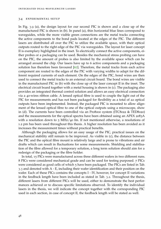
integrated dual-wavelength lasers
3.4 experimental setup
In Fig. 3.9 (a), the design layout for our second PIC is shown and a close up of themanufactured PIC is shown in (b). In panel (a), thin horizontal blue lines correspond towaveguides, while the more visible green connections are the metal tracks connectingthe active components to the bond pads located at the edges of the PIC. The differentlasers are distributed all over the PIC to utilize the available space, with their opticaloutputs routed to the right edge of the PIC via waveguides. The layout for laser conceptII is exemplary highlighted in the inset. To electrically connect the active components, ei-ther probes or a packaging can be used. Besides the mechanical stress probing can haveon the PIC, the amount of probes is also limited by the available space which can bearranged around the chip. Our lasers have up to 6 active components and a packagingsolution has therefore been favoured [67]. Therefore, the metal tracks from each activecomponent are routed to the edges of the PIC with varying widths to adapt for the dif-ferent required currents of each element. On the edges of the PIC, bond wires are thenused to connect the metal tracks to an external circuit board. The bond wires are visiblein the manufactured PIC in (b) with the close up of the laser concept II in the inset. Theelectrical circuit board together with a metal housing is shown in (c). The packaging alsoprovides an integrated thermal control solution and allows an easy electrical connectionvia a 40-wires ribbon cable. A lensed optical fibre is used to couple the light out of thePIC for measurements and has not been packaged for flexibility as a total of 22 opticaloutputs have been implemented. Instead, the packaged PIC is mounted to allow align-ment of the lensed optical fibre to one of the optical outputs using a microscope, showin (d). The currents have been controlled via an Pro8000 system (ITC8022 & TED8020)and the measurements for the optical spectra have been obtained using an APEX 2083Awith a resolution down to 5 MHz/40 fm. If not mentioned otherwise, a resolutions of1.2 pm has been used throughout this thesis. A higher resolution has been avoided as itincreases the measurement times without practical benefits.
Although the packaging allows for an easy usage of the PIC, practical issues on themechanical stability still remain to be improved. As visible in (c), the distance betweenthe PIC and the optical fibre mount is relatively large and is prone to vibrations and airdrafts which can result in fluctuations for some measurements. Shielding and stabilisa-tion of the fibre allowed for a temporary solution, a long term solution should aim for aredesign of the packaging or the fibre holder.
In total, 15 PICs were manufactured across three different wafers in two different runs.8 PICs were considered mechanical grade and can be used for testing purposed. 7 PICswere considered as good cells of which 5 have been packaged. The PICs are listed in Tab.3.3 and denoted with A - E, including their wafer identification and their position on thewafer. Each of these PICs contains the concepts I - IV, however, for concept II variationsin the feedback length have been included as stated in Tab. 3.2. Throughout the thesis,different lasers from different PICs will be used, either to demonstrate the best perfor-mances achieved or to discuss specific limitations observed. To identify the individuallasers in the thesis, we will indicate the concept together with the corresponding PICused in each section, in case of concept II, the feedback length will be stated as well.
48
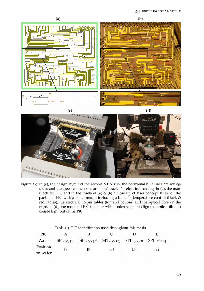
3.4 experimental setup
(a) (b)
(c) (d)
Figure 3.9: In (a), the design layout of the second MPW run, the horizontal blue lines are waveg-uides and the green connections are metal tracks for electrical routing. In (b), the man-ufactured PIC and in the insets of (a) & (b) a close up of laser concept II. In (c), thepackaged PIC with a metal mount including a build in temperature control (black &red cables), the electrical 40-pin cables (top and bottom) and the optical fibre on theright. In (d), the mounted PIC together with a microscope to align the optical fibre tocouple light out of the PIC.
Table 3.3: PIC identification used throughout this thesis.
PIC A B C D E
Wafer SPL 553-5 SPL 553-6 SPL 553-5 SPL 553-6 SPL 461-4
Positionon wafer
J8 J8 B8 B8 F11
49
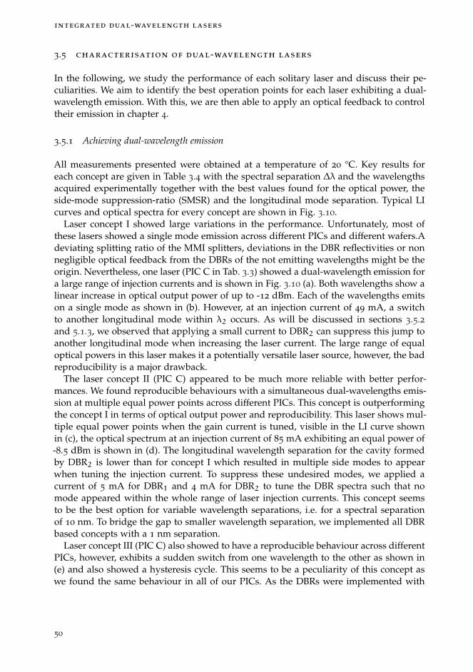
integrated dual-wavelength lasers
3.5 characterisation of dual-wavelength lasers
In the following, we study the performance of each solitary laser and discuss their pe-culiarities. We aim to identify the best operation points for each laser exhibiting a dual-wavelength emission. With this, we are then able to apply an optical feedback to controltheir emission in chapter 4.
3.5.1 Achieving dual-wavelength emission
All measurements presented were obtained at a temperature of 20 °C. Key results foreach concept are given in Table 3.4 with the spectral separation ∆λ and the wavelengthsacquired experimentally together with the best values found for the optical power, theside-mode suppression-ratio (SMSR) and the longitudinal mode separation. Typical LIcurves and optical spectra for every concept are shown in Fig. 3.10.
Laser concept I showed large variations in the performance. Unfortunately, most ofthese lasers showed a single mode emission across different PICs and different wafers.Adeviating splitting ratio of the MMI splitters, deviations in the DBR reflectivities or nonnegligible optical feedback from the DBRs of the not emitting wavelengths might be theorigin. Nevertheless, one laser (PIC C in Tab. 3.3) showed a dual-wavelength emission fora large range of injection currents and is shown in Fig. 3.10 (a). Both wavelengths show alinear increase in optical output power of up to -12 dBm. Each of the wavelengths emitson a single mode as shown in (b). However, at an injection current of 49 mA, a switchto another longitudinal mode within λ2 occurs. As will be discussed in sections 3.5.2and 5.1.3, we observed that applying a small current to DBR2 can suppress this jump toanother longitudinal mode when increasing the laser current. The large range of equaloptical powers in this laser makes it a potentially versatile laser source, however, the badreproducibility is a major drawback.
The laser concept II (PIC C) appeared to be much more reliable with better perfor-mances. We found reproducible behaviours with a simultaneous dual-wavelengths emis-sion at multiple equal power points across different PICs. This concept is outperformingthe concept I in terms of optical output power and reproducibility. This laser shows mul-tiple equal power points when the gain current is tuned, visible in the LI curve shownin (c), the optical spectrum at an injection current of 85 mA exhibiting an equal power of-8.5 dBm is shown in (d). The longitudinal wavelength separation for the cavity formedby DBR2 is lower than for concept I which resulted in multiple side modes to appearwhen tuning the injection current. To suppress these undesired modes, we applied acurrent of 5 mA for DBR1 and 4 mA for DBR2 to tune the DBR spectra such that nomode appeared within the whole range of laser injection currents. This concept seemsto be the best option for variable wavelength separations, i.e. for a spectral separationof 10 nm. To bridge the gap to smaller wavelength separation, we implemented all DBRbased concepts with a 1 nm separation.
Laser concept III (PIC C) also showed to have a reproducible behaviour across differentPICs, however, exhibits a sudden switch from one wavelength to the other as shown in(e) and also showed a hysteresis cycle. This seems to be a peculiarity of this concept aswe found the same behaviour in all of our PICs. As the DBRs were implemented with
50
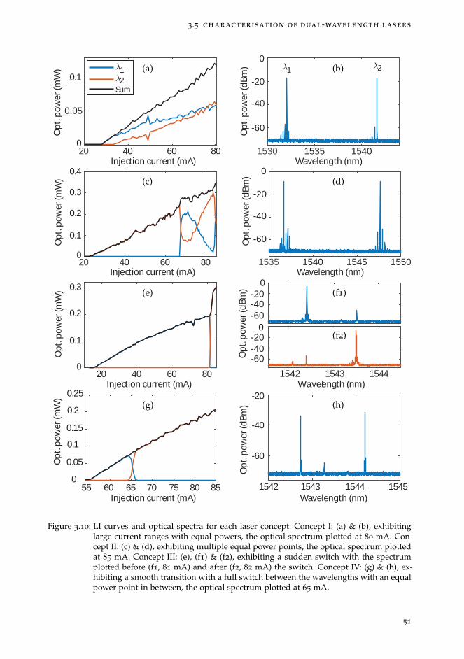
3.5 characterisation of dual-wavelength lasers
20 40 60 800
0.05
0.1
Opt
. pow
er (m
W)
1530 1535 1540Wavelength (nm)
-60
-40
-20
0
Opt
. pow
er (d
Bm)
1535 1540 1545 1550Wavelength (nm)
-60
-40
-20
0
Opt
. pow
er (d
Bm)
20 40 60 800
0.1
0.2
0.3
0.4
Opt
. pow
er (m
W)
20 40 60 800
0.1
0.2
0.3
Opt
. pow
er (m
W)
-60-40-20
0
1542 1543 1544Wavelength (nm)
-60-40-20
0
Opt
. pow
er (d
Bm)
12
Sum
1 2
55 60 65 70 75 80 85Injection current (mA)
0
0.05
0.1
0.15
0.2
Opt
. pow
er (m
W)
1542 1543 1544 1545Wavelength (nm)
-60
-40
-20
Opt
. pow
er (d
Bm)
0.25Injection current (mA)
Injection current (mA)
Injection current (mA)
(a) (b)
(c) (d)
(e) (f1)
(f2)
(g) (h)
Figure 3.10: LI curves and optical spectra for each laser concept: Concept I: (a) & (b), exhibitinglarge current ranges with equal powers, the optical spectrum plotted at 80 mA. Con-cept II: (c) & (d), exhibiting multiple equal power points, the optical spectrum plottedat 85 mA. Concept III: (e), (f1) & (f2), exhibiting a sudden switch with the spectrumplotted before (f1, 81 mA) and after (f2, 82 mA) the switch. Concept IV: (g) & (h), ex-hibiting a smooth transition with a full switch between the wavelengths with an equalpower point in between, the optical spectrum plotted at 65 mA.
51
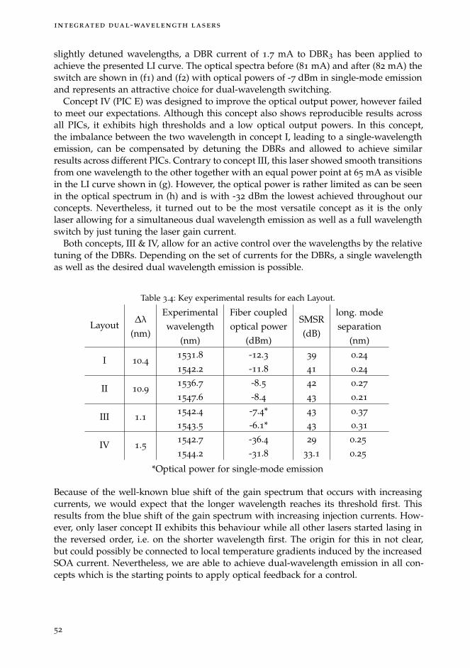
integrated dual-wavelength lasers
slightly detuned wavelengths, a DBR current of 1.7 mA to DBR3 has been applied toachieve the presented LI curve. The optical spectra before (81 mA) and after (82 mA) theswitch are shown in (f1) and (f2) with optical powers of -7 dBm in single-mode emissionand represents an attractive choice for dual-wavelength switching.
Concept IV (PIC E) was designed to improve the optical output power, however failedto meet our expectations. Although this concept also shows reproducible results acrossall PICs, it exhibits high thresholds and a low optical output powers. In this concept,the imbalance between the two wavelength in concept I, leading to a single-wavelengthemission, can be compensated by detuning the DBRs and allowed to achieve similarresults across different PICs. Contrary to concept III, this laser showed smooth transitionsfrom one wavelength to the other together with an equal power point at 65 mA as visiblein the LI curve shown in (g). However, the optical power is rather limited as can be seenin the optical spectrum in (h) and is with -32 dBm the lowest achieved throughout ourconcepts. Nevertheless, it turned out to be the most versatile concept as it is the onlylaser allowing for a simultaneous dual wavelength emission as well as a full wavelengthswitch by just tuning the laser gain current.
Both concepts, III & IV, allow for an active control over the wavelengths by the relativetuning of the DBRs. Depending on the set of currents for the DBRs, a single wavelengthas well as the desired dual wavelength emission is possible.
Table 3.4: Key experimental results for each Layout.
Layout∆λ
(nm)
Experimentalwavelength
(nm)
Fiber coupledoptical power
(dBm)
SMSR(dB)
long. modeseparation
(nm)
I 10.41531.81542.2
-12.3-11.8
39
41
0.24
0.24
II 10.91536.71547.6
-8.5-8.4
42
43
0.27
0.21
III 1.11542.41543.5
-7.4*-6.1*
43
43
0.37
0.31
IV 1.51542.71544.2
-36.4-31.8
29
33.10.25
0.25
*Optical power for single-mode emission
Because of the well-known blue shift of the gain spectrum that occurs with increasingcurrents, we would expect that the longer wavelength reaches its threshold first. Thisresults from the blue shift of the gain spectrum with increasing injection currents. How-ever, only laser concept II exhibits this behaviour while all other lasers started lasing inthe reversed order, i.e. on the shorter wavelength first. The origin for this in not clear,but could possibly be connected to local temperature gradients induced by the increasedSOA current. Nevertheless, we are able to achieve dual-wavelength emission in all con-cepts which is the starting points to apply optical feedback for a control.
52

3.5 characterisation of dual-wavelength lasers
We found that the laser wavelengths were not very accurately predicted by our sim-ulation (neither the wavelength nor the wavelength splitting): they have been shifted toshorter as well as to longer wavelengths, indicating high variances in the target wave-lengths of the DBRs across different wafers. Moreover, the wavelength separation is ofmajor importance, we found severe variations across our lasers with spectral separa-tions of about 10 % in all of our lasers as denoted in Tab. 3.4. A tuning of the DBRswas expected to allow for a match of the experimental- and design-wavelengths in thisevent. Unfortunately, the DBR tuning lead to a single-wavelength emission instead of achange in the spectral separation. This is caused by a reduction in the DBR reflectivitywith increasing DBR current and will be discussed in the following. The impact of theDBR tuning onto an laser simultaneously emitting on two wavelengths and the resultingsingle-wavelength emission will be discussed in section 5.1.3.
3.5.2 DBR characterisation
We have seen different impacts of a DBR tuning onto the laser emission in the exper-iments. By tuning the DBR current, we were able to trigger the second wavelength toachieve a dual-wavelength emission or could limit the number of emitting modes byincreasing the DBR current. Here, we focus onto the spectral response of a DBR to un-derstand the origin of these behaviours. We study DBR2 of laser concept II from PIc(C) when subject to a DBR current as a representative example, the same behaviours arefound in other DBRs. One side of this DBR has been connected to the laser and the otherside has been routed to the edge of the PIC for characterisation. We used an optical cir-culator to separate the beams coupled into and out of the PIC and used a tunable lasersource to measured the reflection spectrum of the DBR via an OSA. The work presentedin this section has been achieved in the framework of the master thesis of Robbe de Mey,under supervision of M.Sc. R. Pawlus and Prof. M. Virte [68].The DBR has a length of 350 µm, is centred at a wavelength of 1535 nm and allows fora maximum current of 21 mA. The resulting reflection spectra are shown in Fig. 3.11 (a).The modulations visible around the maxima result from back-reflections from the edgeof the PIC when coupling light onto the waveguide. With increasing DBR current, thereflectivity spectrum shifts to shorter wavelengths while also decreasing in width and inreflectivity. The evolution of the spectral width with increasing current is shown in (b)and results in a decrease of about 0.3 nm. The evolution of the reflectivity is shown in (c)with a reduction in reflectivity of 1.2 dB.
As we have only limited control ability over the lasers, especially for laser layouts I &II, this behaviour could be exploited to our advantage (though overall quite detrimental).As some lasers only show single-wavelength emission, a current can be applied to theDBR of the emitting wavelength to reduce its reflectivity and increase its losses. In somecases, this allowed to trigger the suppressed mode and lead to a dual-wavelength emis-sion. In other cases when the laser was emitting simultaneously on two wavelengthstogether with multiple undesired side modes, a small DBR current lead to a selectionof one particular mode while suppressing the side modes. Thus, leading to an idealdual-wavelength emission on two modes and might be related to two effects at once,the reduction in spectral bandwidth and the tuning of the wavelength. The narrower
53

integrated dual-wavelength lasers
(a)
0 5 10 15 20DBR current (mA)
-28
-27.5
-27
-26.5
-26
Max
ref
lect
ivity
(dB
m)
1.2
1.4
1.6
Spe
ctra
l wid
th (
nm)
(b)
(c)
Figure 3.11: The spectral evolution of the DBR is shown in panel (a), the current is tuned from 0 mAto 21 mA, shifting the optical spectrum to shorter wavelengths. In (b), the evolution ofthe spectral width as a function of the DBR current. In (c), the reduction in reflectivityas a function of the DBR current.
DBR spectrum allows for an easier selection of a particular mode and the shift alignsthe central DBR wavelength with the longitudinal mode. Moreover, as this also reducesthe reflectivity, a too large DBR current can lead to a complete suppression of one ofthe wavelength up to a point of a single wavelength emission. This peculiarity will bediscussed in detail in section 5.1.3 as it limits the performance of our lasers.
The temperature of the PIC has also a major impact on the DBR performance, as shownfor different LI curves ranging in temperature from 15
◦C to 35◦C in 5
◦C steps in Fig.3.12 (a). Here, we characterise the laser concept IV as it allowed for a single-wavelengthemission to conduct these measurements and a direct access to also characterise theDBR. At a temperature of 15
◦C, we find a laser threshold of 38 mA and the thresholdshifts to 55 mA at 30
◦C, already showing a flattening of the curve. At 35◦C no lasing
could be achieved within the current limit of the SOA. We changed the temperature in arange from 15
◦C to 25◦C and measured the reflection spectra of DBR2, the results are
shown in (b). The DBR has a length is 450 µm and a central wavelength of 1541.3 nm.While changing the temperature, the spectral width and the reflectivity remain unaltered.The deviations in the maximum reflectivity originate from the realignment if the fibrerequired when the temperature is changed, thus changing the coupled power into andout of the PIC. A shift of 1.2 nm was achieved for the temperature range of 10
◦C, e.g. aspectral shift of 0.12 nm/◦C. Wavelength shifts ranging from 0.11 nm/°C to 0.19 nm/°Chave been observed characterising other DBRs.
Shifting the DBR spectrum with the temperature can be used to set a precise wave-length within the tuning range, however, with the risk of a higher threshold and a loweroptical output power. As our dual-wavelength lasers also exhibit a deviation from thedesign to the experimental wavelengths, we could compensate for it to a certain de-
54

3.5 characterisation of dual-wavelength lasers
40 60 80 100Current (mA)
0
0.1
0.2
0.3
0.4
0.5
0.6
0.7O
pt. p
ower
(m
W)
(a)
1540 1541 1542 1543 1544 1545
Wavelength (nm)
-40
-35
-30
-25
-20
-15
-10
Ref
lect
ed p
ower
(dB
m)
(b)
Figure 3.12: In (a), the LI curve for temperature from 15◦C to 35
◦C is shown, the threshold shiftsto higher currents with increasing temperature. At a temperature of 35
◦C, no lasingis achieved. In (b), the spectral evolution of the DBR for a temperature range from15
◦C to 25◦C is shown, an increase in temperature shifts the spectrum to longer
wavelengths by 1.2 nm.
gree. However, the crucial parameter for our control approach is the spectral separationbetween the two wavelengths. This feature turned out to remain constant as both wave-length experience the same wavelength shift. Therefore, lower temperatures seem to beadvantageous for higher optical output powers. But, at temperatures around 15
◦C con-densation is visible on the PIC due to humidity and we therefore set our operatingtemperature to 20
◦C for all our experiments. Furthermore, we also found a shift in theDBR spectrum when a nearby device like an SOA or a neighbouring DBR was operatedwith high currents. The resulting temperature gradient within the PIC shifted the DBRspectrum to longer wavelengths. Although it would require further investigations to beconfirmed, we think that this feature might be, at least in part, at the origin of the spec-tral evolution opposed to the blue-shift of the gain spectrum that we observed in someof our lasers. Yet, our work does not allow us to confirm it for now.
55

integrated dual-wavelength lasers
3.6 conclusion
To conclude this chapter, we presented four different dual-wavelength laser concepts andoptimized them with the insights gained from a first MPW participation towards a sec-ond generation. For the optimization, we used a circuit simulator to determine optimalDBR lengths for dual-wavelength emission, but also to determine the exact wavelengtheach of the lasers will emit on. We then presented experimental results for each laserand found simultaneous or sequential dual-wavelength emission across all structuresand discussed their peculiarities. Layouts II & III showed to be the best performing con-cepts with high output powers and reproducible results across different PICs and waferswhich suggests a good robustness of the designs. Finally, we also presented DBR char-acteristics under varying currents and temperatures and discussed their impact on thelaser emission. With the resulting wavelengths obtained from the simulations, we imple-mented customized feedback cavities presented in the next chapter. Together with theoperation points for dual-wavelength emission determined in this chapter, we will thenbe able to demonstrate the control capabilities of our feedback approach.
56
4 A M P L I T U D E C O N T R O L V I AP H A S E - C O N T R O L L E D O P T I C A L F E E D B A C K
In this chapter, we use the optical feedback phase to control the laser emission of ourdual-wavelength lasers. In the first section 4.1, we discuss the implementation of the op-tical feedback sections onto the PIC. With the knowledge of the expected wavelength foreach laser concept from the simulations, we implement a customized feedback sectionfor each laser. In the second section 4.2, we present the experimental results on the ampli-tude control for each laser concept, using the operation points for the dual-wavelengthlasers determined in the previous chapter. In the next section 4.3, we study the impact ofa varying laser and feedback currents to evaluate control potential when deviating froman equal-power point and map the maximal operating range of our control approach. Inthe last section 4.4, we discuss the switching speed between the different wavelengthswhich are competitive to other solutions implemented on this MPW platform.
57

amplitude control via phase controlled optical feedback
DWL MIR
External cavity length
EOPM
SOA
MMI
Figure 4.1: Schematic of the implemented feedback section. The emission of the dual-wavelengthlaser is split into a measurement and feedback path. The light in the feedback sectionpasses an SOA to control the feedback strength, an EOPM to control the feedback phaseand is reflected back towards the laser using an MIR.
4.1 feedback cavity design on pic
For each laser, an optical feedback section with a specific external cavity length is mono-lithically integrated, schematically shown in Fig. 4.1. The output from each laser concept,either from the 2-port MMI splitter for concepts I & II or from the DBR output for con-cepts III & IV, is guided into an 2x2 MMI splitter with a splitting ratio of 85:15. The 15 %are guided to the feedback section, passing an SOA and an EOPM before being reflectedback to the laser cavity via an 1-port MIR. The SOA has a length of 300 µm, identicalfor all lasers, and allows to control the feedback strength. The EOPM has a length of1200 µm, also identical for all lasers, and allows to achieve a feedback delay of 2π for adesign voltage of 8 V which results from the light passing the EOPM twice. The EOPMsections have a breakdown voltage above 15 V. With the 1200 µm length used here, thisupper limit correspond to feedback phase shift of 4π (two times 2π for one round trip).Each of these active components is separated by an isolation section, ranging between30 µm and 75 µm, depending on the neighbouring components, to avoid any cross-talks.Then, a 1-port MIR is used to reflect the light back towards the laser cavity. Accumulat-ing the splitting ratios and reflectivities for all components results to about 1.5 % of thelight being send back towards the laser cavity. This is valid when assuming no lossesof the light for the round trip and transparency of the SOA. As the reflectivities of theoutcoupling mirrors differ for each laser concept, the actual amount of feedback enteringthe laser cavity varies. With a reflectivity of 50 % for the MIR, about 0.8 % is expectedto be coupled back into the laser cavities of concept I & II while about 0.6 % is expectedto be coupled back for laser concept III with a DBR3 reflectivity of 58 %. Laser conceptIV is rather special because of the DBR transparencies to each others wavelengths. Thisallows the optical feedback to fully enter the laser cavity via the transparent DBR and toabout 4 % via the reflective DBR. Together with the 1x2 MMI splitter to merge the laserbeams in this laser, about 0.4 % are expected to be coupled into the laser cavity.
An unknown factor is the required current for the feedback SOA to reach transparency.Due to the gain spectrum of the SOA, this characteristic is wavelength dependent andcannot be easily estimated from our available data. Dedicated test structures need to beimplemented in a future design to estimate it. This is, in fact, quite important in our case:
58

4.1 feedback cavity design on pic
Below transparency, the SOA acts as an attenuator while it amplifies the feedback abovetransparency.
As each laser is expected to emit on specific wavelengths, their feedback cavities haveto be adapted in length individually. To achieve this, the waveguide between the EOPMsection and the 1-port MIR is implemented with different lengths. To calculate the cor-responding feedback cavity length, the spectral separation of the wavelengths has to beused to calculate the beat length Lbeat = λ1·λ2
n·(λ1−λ2)for λ1 > λ2 with n being the re-
fractive index. To obtain the desired relative phase shift of π after a full round trip inthe feedback cavity, a delay of half the length Lbeat is required. This length can be ex-tended by a number m of full cycles of the beat length to accommodate for additionalcomponents to be placed inside the cavity and it follows:
Ldelay = (m+ 0.5) · Lbeat (4.1)
m should be chosen to be minimal to improve robustness against high optical feedbackstrengths as discussed in section 1.5. To obtain the length of the physical feedback cavity,Ldelay needs to be divided by a factor of two to obtain the implemented lengths stated inTab. 3.2 on page 47, ranging from 2400 µm to 4850 µm. For laser II, two identical laserswhere implemented together with two different feedback cavity lengths to study theinfluence of much larger delay lengths. All feedback lengths are expected to be withinthe short cavity regime, thus, reducing the risk of potential dynamical behaviour to aminimum. The second output of the MMI with a transmission of 85 % is guided to theedge of the PIC to couple the light out for measurements. To avoid reflections from theedge of the PIC, an angled facet of 7
◦ is implemented together with an anti-reflectioncoating to reduce the reflections below -40 dB. This is much lower than the expectedfeedback strength from our feedback section and should therefore not influence ourcontrol approach.
59
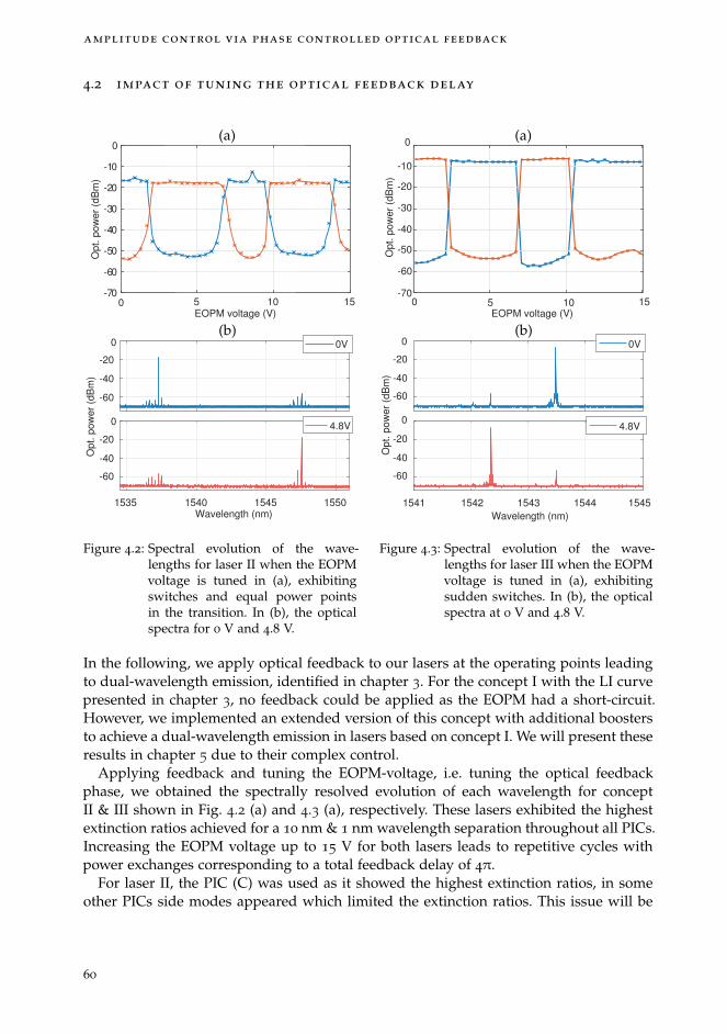
amplitude control via phase controlled optical feedback
4.2 impact of tuning the optical feedback delay
0 10EOPM voltage (V)
-70
-60
-50
-40
-30
-20
-10
0
Op
t. p
ow
er
(dB
m)
-60
-40
-20
0 0V
1535 1540 1545 1550Wavelength (nm)
-60
-40
-20
0
Op
t. p
ow
er
(dB
m)
4.8V
5 15
(a)
(b)
Figure 4.2: Spectral evolution of the wave-lengths for laser II when the EOPMvoltage is tuned in (a), exhibitingswitches and equal power pointsin the transition. In (b), the opticalspectra for 0 V and 4.8 V.
10 15EOPM voltage (V)
-60
-40
-20
0 0V
1541 1542 1543 1544 1545
Wavelength (nm)
-60
-40
-20
0
Op
t. p
ow
er
(dB
m)
4.8V
5-70
0
-60
-50
-40
-30
-20
-10
Op
t. p
ow
er
(dB
m)
0(a)
(b)
Figure 4.3: Spectral evolution of the wave-lengths for laser III when the EOPMvoltage is tuned in (a), exhibitingsudden switches. In (b), the opticalspectra at 0 V and 4.8 V.
In the following, we apply optical feedback to our lasers at the operating points leadingto dual-wavelength emission, identified in chapter 3. For the concept I with the LI curvepresented in chapter 3, no feedback could be applied as the EOPM had a short-circuit.However, we implemented an extended version of this concept with additional boostersto achieve a dual-wavelength emission in lasers based on concept I. We will present theseresults in chapter 5 due to their complex control.
Applying feedback and tuning the EOPM-voltage, i.e. tuning the optical feedbackphase, we obtained the spectrally resolved evolution of each wavelength for conceptII & III shown in Fig. 4.2 (a) and 4.3 (a), respectively. These lasers exhibited the highestextinction ratios achieved for a 10 nm & 1 nm wavelength separation throughout all PICs.Increasing the EOPM voltage up to 15 V for both lasers leads to repetitive cycles withpower exchanges corresponding to a total feedback delay of 4π.
For laser II, the PIC (C) was used as it showed the highest extinction ratios, in someother PICs side modes appeared which limited the extinction ratios. This issue will be
60

4.2 impact of tuning the optical feedback delay
discussed in chapter 5. An extinction ratio of up to 38.6 dB has been achieved as shownin Fig. 4.2 (a). The two wavelengths are shown in panel (b) for 0 V & 4.8 V. Setting theEOPM voltage precisely to the wavelength transition points allows to balance their opti-cal output powers to achieve a simultaneous dual-wavelength emission. To obtain theseresults, a feedback current of 12 mA has been applied. This laser concept demonstratedto be quite robust and showed similar results across other PICs. However, the overallperformance varies as undesired side modes appeared in some cases and limited theperformance severely as will be discussed in detail in chapter 5.
10 15
EOPM voltage (V)
-70
-60
-50
-40
-30
-20
-10
0
Op
t. p
ow
er
(dB
m)
1
2
3
-60
-40
-20
0
-60
-40
-20
0
Op
t. p
ow
er
(dB
m)
1541.5 1542 1542.5 1543 1543.5
Wavelength (nm)
-60
-40
-20
0
1.3V
3.6V
5.5V
0 5
(a) (b)
Figure 4.4: In (a), sequential selection of three wavelengths by a tuning of the feedback phase. In(b), the corresponding optical spectra for the individually selected wavelengths.
For laser III, the PIC (C) was used as it exhibited the highest optical power and the high-est suppression ratio, however, PIC (A) & (B) showed almost identical results. For thisconcept, we obtained even higher extinction ration of up to 50.5 dB as displayed in Fig.4.3 (a). It shows the spectrally resolved evolution for each wavelength, exhibiting multi-ple sudden switches between the wavelengths. As already observed for the solitary laser,it is not possible to achieve a simultaneous emission on both wavelengths in this laser,even using the phase controlled optical feedback. We also found a hysteresis cycle ofabout 0.6 V when increasing and decreasing the EOPM voltage. However, the hysteresisas well as the sudden switches are related to the laser itself and not to the feedback con-trol approach. The optical spectra for voltages of 0 V and 4.8 V are shown in (b). Beyond14 V, we observe a saturation as λ1 can not be triggered any more at these high voltages.A feedback current of 6.9 mA has been applied to achieve this result. Furthermore, asthe DBRs can be individually tuned, we were also able to identify an operation point ex-hibiting three distinct modes which can be individually selected by tuning the feedbackphase. Their spectral evolution is shown in Fig. 4.4 (a) and exhibits a sequential selectionof the three modes when the feedback phase is tuned. The emission of λ1, λ2 and λ3 areshown in (b) in blue, red and yellow, respectively. We found the same behaviour withthe possibility to select two or three modes and sequentially select them also in PIC (B),suggesting this behaviour to be a laser specific characteristic. To obtain these results, the
61

amplitude control via phase controlled optical feedback
operation point of the laser was changed to an injection current of 60.1 mA, togetherwith a higher feedback current of 10.2 mA and a DBR3 current of 6 mA to detune theDBRs such that three neighbouring modes are involved in the emission.
-60
-40
-20
1542 1543 1544 1545
Wavelength (nm)
-60
-40
-20
Op
t. p
ow
er
(dB
m)
EOPM voltage (V)
-60
-50
-40
-30
-20
Op
t. p
ow
er
(dB
m)
0 1 2 3 5 6 7 8
(a) (b)
Figure 4.5: Spectral evolution of the wavelength when changing the feedback phase for concept IVin (a). The optical spectra is shown in (d) for 0 V and 5 V.
For Laser IV, the PIC (E) was used, although other lasers showed even higher extinctionratios (about 5 dB), this laser showed to emit only at two wavelengths for any given laseror feedback current. For this reason, it will be used also for further studies in the follow-ing section and is therefore presented here. Without optical feedback, the equal-powerpoint is around 65 mA, however, applying feedback to this operating point resulted inthe sole emission of one wavelength and a tuning of the optical feedback phase had noimpact. Only an increase of the laser current up to 71.5 mA allowed to obtain a switchand is shown in Fig. 4.5 (a) with an extinction ratio of up to 29 dB. The EOPM voltagewas limited to 8 V, corresponding to a phase shift of 2π which allows for a full switchingcycle between the wavelengths and avoids excessive load. In (b), the two wavelengths areshown with a spectral separation of 1.5 nm without the appearance of any side modes.The origin of the required increase in injection current to obtain the switch is not fullyunderstood yet. This laser also exhibits a very low output power, but is the only laserexhibiting a full switch between the wavelengths as well as an equal optical power whenthe injection current and the feedback phase are tuned. Therefore, it will be used to studyvariations in the laser and injection current in the following sections.
To conclude, we found deviations in the spectral separation of at least 10 % in all of ourlasers. Nevertheless, we were able to demonstrate high extinction ratios for the presentedconcept. This is a good indication of the robustness of the control approach as it showsa relatively low demand on precise relative phase shifts between the wavelengths. Inthe simulations discussed in chapter 2, we identified a relative phase shift of π betweentwo wavelengths to be optimal to transition between the points (φ1,φ2) = (0,π) →(π, 0). However, also suboptimal relative phase shifts allow for a full switch. They arerepresented by diagonal transitions, parallel to the arrow shown in Fig. 2.5 on page 24,and result from a mismatch of the spectral separations to the feedback cavity lengths.
62

4.2 impact of tuning the optical feedback delay
Nevertheless, we achieve a good performances for each laser concept despite thesedeviations in the spectral separations. Furthermore, we found that the EOPM voltageallows for large margins as a particular wavelength is selected for a relatively large rangeof voltages. It confirms that a precise setting of the feedback phase is not crucial.
To apply the optical feedback for the different concepts, we increased the feedbackcurrent until we achieved a full suppression of one wavelength. For laser concepts II &III, the starting point for this suppression was around 5 mA, below this feedback current,no influence on the optical spectra has been found. For laser concept IV, a lower feedbackcurrent of 3 mA already showed an impact due to the mutual DBR transparencies. Whentuning the EOPM voltage, the concepts II & IV showed smooth transitions between thewavelengths, allowing for an easy adjustment of an equal optical power point while thelaser concept III exhibited sudden jumps between the wavelengths as well as a hysteresiscycle. Overall, lasers II & III showed the best performances with the highest extinctionratios and high optical power. For concept III, even a discrete tuning of three modescould be demonstrated. The operation of the solitary lasers I & IV is rather difficultwhereas the feedback control also allowed for high extinction ratios in these lasers.
So far, we only applied the control approach to equal optical power points. In thefollowing section, we analyse to which extend a control can be achieved when divertingfrom this point. We will use laser IV as the smooth and full transition between thewavelengths for the solitary laser as well as the contribution of only two wavelengthwithout any side modes makes this laser an ideal candidate to conduct this experiment.
63
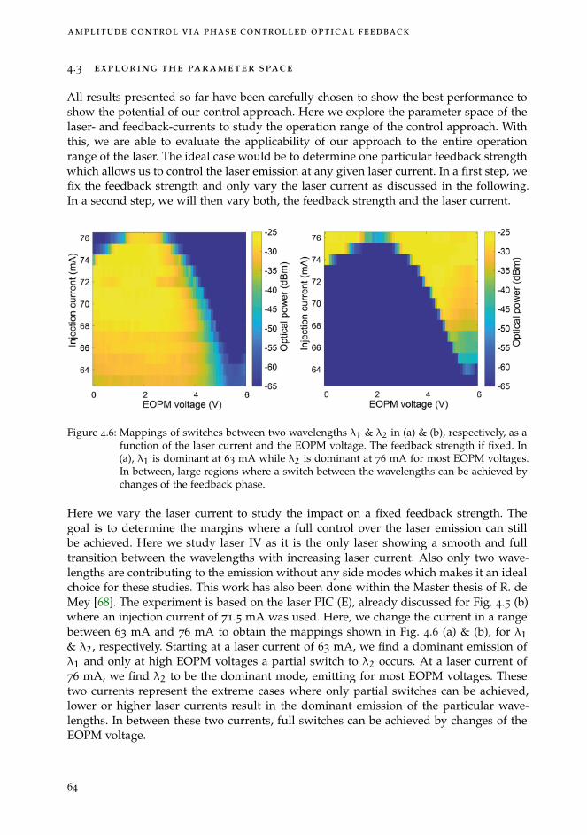
amplitude control via phase controlled optical feedback
4.3 exploring the parameter space
All results presented so far have been carefully chosen to show the best performance toshow the potential of our control approach. Here we explore the parameter space of thelaser- and feedback-currents to study the operation range of the control approach. Withthis, we are able to evaluate the applicability of our approach to the entire operationrange of the laser. The ideal case would be to determine one particular feedback strengthwhich allows us to control the laser emission at any given laser current. In a first step, wefix the feedback strength and only vary the laser current as discussed in the following.In a second step, we will then vary both, the feedback strength and the laser current.
Figure 4.6: Mappings of switches between two wavelengths λ1 & λ2 in (a) & (b), respectively, as afunction of the laser current and the EOPM voltage. The feedback strength if fixed. In(a), λ1 is dominant at 63 mA while λ2 is dominant at 76 mA for most EOPM voltages.In between, large regions where a switch between the wavelengths can be achieved bychanges of the feedback phase.
Here we vary the laser current to study the impact on a fixed feedback strength. Thegoal is to determine the margins where a full control over the laser emission can stillbe achieved. Here we study laser IV as it is the only laser showing a smooth and fulltransition between the wavelengths with increasing laser current. Also only two wave-lengths are contributing to the emission without any side modes which makes it an idealchoice for these studies. This work has also been done within the Master thesis of R. deMey [68]. The experiment is based on the laser PIC (E), already discussed for Fig. 4.5 (b)where an injection current of 71.5 mA was used. Here, we change the current in a rangebetween 63 mA and 76 mA to obtain the mappings shown in Fig. 4.6 (a) & (b), for λ1& λ2, respectively. Starting at a laser current of 63 mA, we find a dominant emission ofλ1 and only at high EOPM voltages a partial switch to λ2 occurs. At a laser current of76 mA, we find λ2 to be the dominant mode, emitting for most EOPM voltages. Thesetwo currents represent the extreme cases where only partial switches can be achieved,lower or higher laser currents result in the dominant emission of the particular wave-lengths. In between these two currents, full switches can be achieved by changes of theEOPM voltage.
64

4.3 exploring the parameter space
In the solitary laser without feedback, the transition between the wavelengths occurswithin a range of 2 mA. This result shows, that applying our control approach allowsto extend the operation range to a larger laser current range of 13 mA. Furthermore,these results were obtained with a fixed optical feedback strength, however, in the sim-ulations we already discussed that a higher feedback strength can be used to increasethe operating range in case partial switches are achieved and will be discussed in thefollowing.
We study the maximal achievable control range over the laser emission by varyingthe optical feedback strength and the laser current to achieve the mappings shown inFig. 4.7. The measurements have been obtained by sweeping the EOPM voltage for everycombination of laser and feedback current. To present these mapping, we had to reducethe parameter space and merged the EOPM voltages to one figure of merit, describing ifa switch has been achieved or not when the EOPM voltage is tuned.
To analyse this, we set two different thresholds, one corresponding to the wavelengthbeing turned on and one for being turned off. To determine if a switch is achieved, eachof the wavelengths has to trigger both of the thresholds when the EOPM voltage is tuned,i.e. it is either being turned on or off when the voltage is tuned. This procedure has beendone with both wavelengths individually and a switch was only registered when bothwavelengths exhibited a switch at the same EOPM voltages. A switch was consideredwhen the wavelengths showed a power exchange of at least 10 dB.
To obtain the experimental results, we used an optical filter to select a wavelengthand measured the optical power with a photo diode. This was a fast measurement tech-nique, however, required the sequential measurements of both wavelength individually.Comparing the measurement times to using an OSA for each parameter setting, wouldhave result in a ten-fold measurement time. Nevertheless, we still encountered a dropin the fibre coupled optical power over time, hence, the obtained results do not allow tocompare absolute values in amplitude. Due to the use of the photo diode, we also didnot obtain any indication on the influence of a multi-mode emission affecting the extinc-tion ratios. Furthermore, we also discard information on which wavelength is emittingat which EOPM voltage and even if dynamical behaviour occurs and only focus on thequestion if a switch between the wavelengths can be achieved or not.
We mapped the individual operation ranges of laser concept I , II and IV, shown in Fig.4.7. The results are represented by white and black markers, representing no switchesand full switches, repectively.
In (a), the mapping for laser IV, already discussed in section 4.6, is shown. The PIC (E)is used which exhibits only two modes was therefore the ideal choice to perform thesemeasurements. We found that the operation range can be extended until the maximallaser current when the feedback current is also increased. With increasing laser current,the required feedback has also to be increased to maintain a full control. This is con-nected to the shift of the gain spectrum with increasing laser current. This shows thatthe feedback strength enables a much larger operation range in which the laser emissioncan be controlled.
In Fig. 4.7 (b), the mapping for laser I of PIC (C) and in (c) & (d) the mappings for twolaser concepts II are shown for PIC (B) & (C), respectively. Large areas exhibiting a fullswitch are found in all mappings. A minimal amount of feedback has to be applied toachieve switching, ranging from 5 mA to 10 mA. For large laser and feedback currents
65

amplitude control via phase controlled optical feedback
areas without switches are also visible where one wavelength is dominant. Differentwhite areas can also correspond to different wavelengths being dominant, in particularabove and below the black areas in (a) and (c). For both lasers II with different feedbacklengths, we were able to obtain large areas exhibiting full switches.
The areas for large laser and feedback currents in panel (b) & (d) exhibiting alternatingresults, i.e. multiple switches and no switches next to each other, could be related to amulti modes emission as this severely limits the extinction ratios and might thereforenot be sufficiently reduced to trigger the 10 dB detection threshold. However, this is alaser specific characteristic and requires further improvements of the lasers itself. Withan improved dual-wavelength laser, the mapping suggests that a full control of the emis-sion could be possible for large laser and feedback currents. This demonstrates that thefeedback based control approach is quite versatile and can be adapted to a variety ofdifferent laser operation points.
66

4.3 exploring the parameter space
Feedback current (mA)
55
60
65
70
75
80
85
La
se
r cu
rre
nt (m
A)
Feedback current (mA)
30
40
50
60
70
80
La
se
r cu
rre
nt (m
A)
Feedback current (mA)
30
40
50
60
70
80
La
se
r cu
rre
nt (m
A)
Feedback current (mA)
30
40
50
60
70
80
La
se
r cu
rre
nt (m
A)
403020100 403020100
403020100 403020100
(a) (b)
(c) (d)
Figure 4.7: Mappings showing the switching potential for varying laser and feedback current.Black markers represent full switches and white marker represent no switches. In (a),laser IV is shown, in (b) laser I and in (c) & (d), laser II is shown. Adapting both pa-rameters allows to achieve a full control over the laser emission for almost all lasercurrents.
67
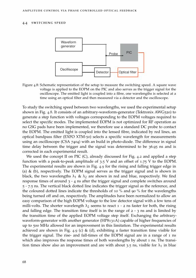
amplitude control via phase controlled optical feedback
4.4 switching speed
Waveform
generator
Oscilliscope
PICProbe
Detector Optical filter
Figure 4.8: Schematic representation of the setup to measure the switching speed. A square wavevoltage is applied to the EOPM on the PIC and also serves as the trigger signal for theoscilloscope. The emitted light is coupled into a fibre, one wavelengths is selected at atime using an optical filter and then measured via a detector and the oscilloscope.
To study the switching speed between two wavelengths, we used the experimental setupshown in Fig. 4.8. It consists of an arbitrary-waveform-generator (Tektronix AWG520) togenerate a step function with voltages corresponding to the EOPM voltages required toselect the specific modes. The implemented EOPM is not optimized for RF operation asno GSG pads have been implemented, we therefore use a standard DC probe to contactthe EOPM. The emitted light is coupled into the lensed fibre, indicated by red lines, anoptical bandpass filter (EXFO XTM-50) selects a specific wavelength for measurementsusing an oscilloscope (CSA 7404) with an build in photo-diode. The difference in signaltime delay between the trigger and the signal was determined to be 36.95 ns and iscorrected in each experimental result.
We used the concept II on PIC (C), already discussed for Fig. 4.2 and applied a stepfunction with a peak-to-peak amplitude of 3.5 V and an offset of 1.75 V to the EOPM.The experimental results are shown in Fig. 4.9 for the rising and falling trigger edge in(a) & (b), respectively. The EOPM signal serves as the trigger signal and is shown inblack, the two wavelengths λ1 & λ2 are shown in red and blue, respectively. We findresponse times of around 3 - 4 ns after the trigger signal and complete switches around5 - 7.5 ns. The vertical black dotted line indicates the trigger signal as the reference, andthe coloured dotted lines indicate the thresholds of 10 % and 90 % for the wavelengthsbeing turned off and on, respectively. The amplitudes have been normalized to allow aneasy comparison of the high EOPM voltage to the low detector signal with a few tens ofmilli-volts. The shorter wavelength λ2 seems to react 1 - 2 ns faster for both, the risingand falling edge. The transition time itself is in the range of 2 - 3 ns and is limited bythe transition time of the applied EOPM voltage step itself. Exchanging the arbitrary-waveform-generator with another generator (HP8131A) capable of higher frequencies ofup to 500 MHz allowed for an improvement in this limitation. The experimental resultsachieved are shown in Fig. 4.9 (c) & (d), exhibiting a faster transition time visible forthe trigger signal. The rise- and fall-times of the EOPM signal are in a range of 1 nswhich also improves the response times of both wavelengths by about 1 ns. The transi-tion times show also an improvement and are with about 3.5 ns, visible for λ1 in blue
68

4.4 switching speed
Time (ns)
Am
plit
ud
e (
a.u
.)
-0.2
0
0.2
0.4
0.6
0.8
1
1.2
-10 -5 0 5 10 15 20 25 30Time (ns)
Am
plit
ud
e (
a.u
.)
-0.2
0
0.2
0.4
0.6
0.8
1
1.2
-10 -5 0 5 10 15 20 25 30
Time (ns)
Am
plit
ud
e (
a.u
.)
-0.2
0
0.2
0.4
0.6
0.8
1
1.2
-10 -5 0 5 10 15 20 25 30Time (ns)
Am
plit
ud
e (
a.u
.)
-0.2
0
0.2
0.4
0.6
0.8
1
1.2
-10 -5 0 5 10 15 20 25 30
(a) (b)
(c) (d)
Figure 4.9: Switching speed measurements for laser II. In black the trigger signal serving as areference, in blue the mode being turned off and in red the mode being turned on.In (a) & (c), for the rising trigger edge and in (b) & (d) the falling trigger edge. In(c) & (d), the laser and operation points are identical to (a) & (b), however with awaveform generator capable of higher frequencies which results in faster response andswitching times. However, dynamics appear which show the current limitation of thenon optimized setup for RF operation.
in (d), the fastest we obtained. However, the arbitrary-waveform-generator itself showeda transient behaviour and reached its desired amplitude only much later which alsointroduced a corresponding laser response. The varying EOPM voltage also influencesfeedback phase and consequently changes the operation voltage which results in unde-sired power exchanges visible around 6 ns and 25 ns. This represents a current technicallimitation and prevents even faster transition times. As the electro-optic effect used inEOPM is capable of much higher frequencies, a dedicated RF-setup with GSG probescould prevent these modulations to achieve maximal performance. Thorough studies onthe impact of the laser current or the optical feedback strength on the switching timesare currently out of reach as carefully chosen operation points have been used for thesemeasurements. Either undesired modes are triggered or dynamical behaviour appears,
69

amplitude control via phase controlled optical feedback
both hampering the performance. This also limits our interpretation with respect to thepresented simulations. The limitations and potential improvements on this will be dis-cussed in the following chapter 5.
70

4.5 conclusion
4.5 conclusion
In this chapter, we implemented feedback cavities to every laser with an SOA to controlthe feedback strength and an EOPM to control the feedback phase. We then applied ourcontrol approach to the different lasers operated at the equal power points identified inthe laser chapter. We were able to demonstrated switching ratios of up to 50 dB as well asequal power points by only tuning the feedback phase. To investigate the operation rangeof our control approach, we studied different laser currents. We found that the feedbackphase allows to control the laser emission even for laser currents deviating from the equalpower points. We explored also parameter space of laser currents and feedback strengthsto extend the operation range to a maximum. We found that our control approach canbe applied to a large range of laser currents by adapting the feedback strength. Thisshows the flexibility of our control approach which is not limited to single operationpoints. Finally, we investigated the switching times between the wavelengths and foundvalues of down to 3.5 ns. While conducting the experiments presented in the last twochapters, we encountered several limitations in the laser operation. This restricted severalexperiments and did not allow to study important details. In the following chapter, wewill discuss these issues in detail, point out weaknesses in the laser designs and proposeimproved structures for a next MPW participation.
71


5 L I M I TAT I O N S O F P E R F O R M A N C E S
In this chapter, we will highlight the current limitations of our lasers as well as the con-trol approach and propose improvements. In particular, we identified a limited tuningof the spectral wavelength separation or a low wavelength selectivity of the DBRs topossibly result in a multi-mode emission which limits the flexibility of our lasers. Thishinders our study of the control approach and restricts the operation points to only afew sets of parameters. Hence, we were not able to answer two major questions to as-sess the robustness of the control approach so far: First, how the extinction ratio behaveswith varying relative-phase shifts and, second, how the maximal achievable extinctionratio scales for different spectral separations. We followed three different approaches togain further insights into this issue. As the implemented feedback section on our PICsare fixed, we used two external setups, either using a quantum-dot laser or an externalcavity diode laser, together with a freely tunable external feedback delay. The third ap-proach is based on a DBR tuning to change the spectral separation on PIC. Unfortunately,different hurdles and limitation lead to a limited outcome in all three experiments as willbe discussed in the first section 5.1. In the next section 5.2, we will discuss the variabil-ity of our results from different wafers and PICs. After this, we will discuss the poorperformance of concept I and present an extended version of the laser to overcome thepresent limitations. Then, we discuss the impact of a multi-mode emission on the extinc-tion ratio as well as the transient behaviour when switching between two wavelengths.Next, we highlight potential improvements for our integrated laser concepts. The secondgeneration of our PIC design showed convincing results for most of our laser concepts.However, besides the best lasers with good results presented in the chapter 4, it alsorevealed drawbacks and design flaws which we will addressed in section 5.3. Our goalis to identify the most crucial parameters which can lead to substantial improvements intheir performance and to a successful third PIC generation.
73
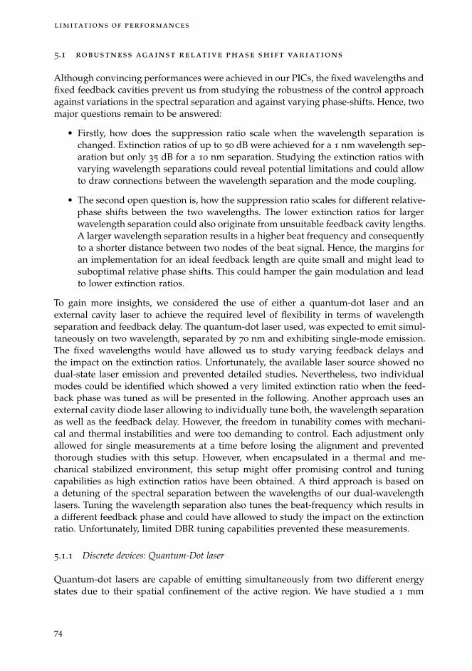
limitations of performances
5.1 robustness against relative phase shift variations
Although convincing performances were achieved in our PICs, the fixed wavelengths andfixed feedback cavities prevent us from studying the robustness of the control approachagainst variations in the spectral separation and against varying phase-shifts. Hence, twomajor questions remain to be answered:
• Firstly, how does the suppression ratio scale when the wavelength separation ischanged. Extinction ratios of up to 50 dB were achieved for a 1 nm wavelength sep-aration but only 35 dB for a 10 nm separation. Studying the extinction ratios withvarying wavelength separations could reveal potential limitations and could allowto draw connections between the wavelength separation and the mode coupling.
• The second open question is, how the suppression ratio scales for different relative-phase shifts between the two wavelengths. The lower extinction ratios for largerwavelength separation could also originate from unsuitable feedback cavity lengths.A larger wavelength separation results in a higher beat frequency and consequentlyto a shorter distance between two nodes of the beat signal. Hence, the margins foran implementation for an ideal feedback length are quite small and might lead tosuboptimal relative phase shifts. This could hamper the gain modulation and leadto lower extinction ratios.
To gain more insights, we considered the use of either a quantum-dot laser and anexternal cavity laser to achieve the required level of flexibility in terms of wavelengthseparation and feedback delay. The quantum-dot laser used, was expected to emit simul-taneously on two wavelength, separated by 70 nm and exhibiting single-mode emission.The fixed wavelengths would have allowed us to study varying feedback delays andthe impact on the extinction ratios. Unfortunately, the available laser source showed nodual-state laser emission and prevented detailed studies. Nevertheless, two individualmodes could be identified which showed a very limited extinction ratio when the feed-back phase was tuned as will be presented in the following. Another approach uses anexternal cavity diode laser allowing to individually tune both, the wavelength separationas well as the feedback delay. However, the freedom in tunability comes with mechani-cal and thermal instabilities and were too demanding to control. Each adjustment onlyallowed for single measurements at a time before losing the alignment and preventedthorough studies with this setup. However, when encapsulated in a thermal and me-chanical stabilized environment, this setup might offer promising control and tuningcapabilities as high extinction ratios have been obtained. A third approach is based ona detuning of the spectral separation between the wavelengths of our dual-wavelengthlasers. Tuning the wavelength separation also tunes the beat-frequency which results ina different feedback phase and could have allowed to study the impact on the extinctionratio. Unfortunately, limited DBR tuning capabilities prevented these measurements.
5.1.1 Discrete devices: Quantum-Dot laser
Quantum-dot lasers are capable of emitting simultaneously from two different energystates due to their spatial confinement of the active region. We have studied a 1 mm
74
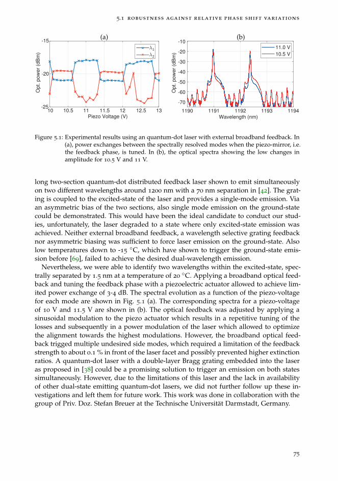
5.1 robustness against relative phase shift variations
10 10.5 11 11.5 12 12.5 13Piezo Voltage (V)
-25
-20
-15O
pt. p
ow
er
(dB
m)
1
2
1190 1191 1192 1193 1194Wavelength (nm)
-70
-60
-50
-40
-30
-20
-10
Op
t. p
ow
er
(dB
m)
11.0 V
10.5 V
(a) (b)
Figure 5.1: Experimental results using an quantum-dot laser with external broadband feedback. In(a), power exchanges between the spectrally resolved modes when the piezo-mirror, i.e.the feedback phase, is tuned. In (b), the optical spectra showing the low changes inamplitude for 10.5 V and 11 V.
long two-section quantum-dot distributed feedback laser shown to emit simultaneouslyon two different wavelengths around 1200 nm with a 70 nm separation in [42]. The grat-ing is coupled to the excited-state of the laser and provides a single-mode emission. Viaan asymmetric bias of the two sections, also single mode emission on the ground-statecould be demonstrated. This would have been the ideal candidate to conduct our stud-ies, unfortunately, the laser degraded to a state where only excited-state emission wasachieved. Neither external broadband feedback, a wavelength selective grating feedbacknor asymmetric biasing was sufficient to force laser emission on the ground-state. Alsolow temperatures down to -15
◦C, which have shown to trigger the ground-state emis-sion before [69], failed to achieve the desired dual-wavelength emission.
Nevertheless, we were able to identify two wavelengths within the excited-state, spec-trally separated by 1.5 nm at a temperature of 20
◦C. Applying a broadband optical feed-back and tuning the feedback phase with a piezoelectric actuator allowed to achieve lim-ited power exchange of 3-4 dB. The spectral evolution as a function of the piezo-voltagefor each mode are shown in Fig. 5.1 (a). The corresponding spectra for a piezo-voltageof 10 V and 11.5 V are shown in (b). The optical feedback was adjusted by applying asinusoidal modulation to the piezo actuator which results in a repetitive tuning of thelosses and subsequently in a power modulation of the laser which allowed to optimizethe alignment towards the highest modulations. However, the broadband optical feed-back trigged multiple undesired side modes, which required a limitation of the feedbackstrength to about 0.1 % in front of the laser facet and possibly prevented higher extinctionratios. A quantum-dot laser with a double-layer Bragg grating embedded into the laseras proposed in [38] could be a promising solution to trigger an emission on both statessimultaneously. However, due to the limitations of this laser and the lack in availabilityof other dual-state emitting quantum-dot lasers, we did not further follow up these in-vestigations and left them for future work. This work was done in collaboration with thegroup of Priv. Doz. Stefan Breuer at the Technische Universität Darmstadt, Germany.
75
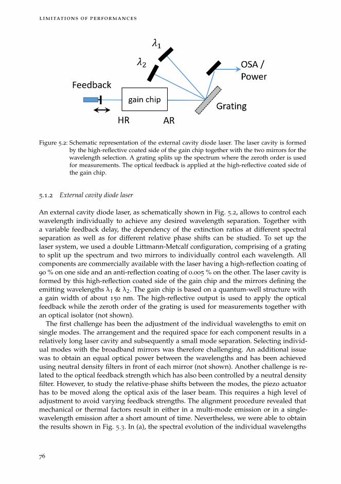
limitations of performances
Figure 5.2: Schematic representation of the external cavity diode laser. The laser cavity is formedby the high-reflective coated side of the gain chip together with the two mirrors for thewavelength selection. A grating splits up the spectrum where the zeroth order is usedfor measurements. The optical feedback is applied at the high-reflective coated side ofthe gain chip.
5.1.2 External cavity diode laser
An external cavity diode laser, as schematically shown in Fig. 5.2, allows to control eachwavelength individually to achieve any desired wavelength separation. Together witha variable feedback delay, the dependency of the extinction ratios at different spectralseparation as well as for different relative phase shifts can be studied. To set up thelaser system, we used a double Littmann-Metcalf configuration, comprising of a gratingto split up the spectrum and two mirrors to individually control each wavelength. Allcomponents are commercially available with the laser having a high-reflection coating of90 % on one side and an anti-reflection coating of 0.005 % on the other. The laser cavity isformed by this high-reflection coated side of the gain chip and the mirrors defining theemitting wavelengths λ1 & λ2. The gain chip is based on a quantum-well structure witha gain width of about 150 nm. The high-reflective output is used to apply the opticalfeedback while the zeroth order of the grating is used for measurements together withan optical isolator (not shown).
The first challenge has been the adjustment of the individual wavelengths to emit onsingle modes. The arrangement and the required space for each component results in arelatively long laser cavity and subsequently a small mode separation. Selecting individ-ual modes with the broadband mirrors was therefore challenging. An additional issuewas to obtain an equal optical power between the wavelengths and has been achievedusing neutral density filters in front of each mirror (not shown). Another challenge is re-lated to the optical feedback strength which has also been controlled by a neutral densityfilter. However, to study the relative-phase shifts between the modes, the piezo actuatorhas to be moved along the optical axis of the laser beam. This requires a high level ofadjustment to avoid varying feedback strengths. The alignment procedure revealed thatmechanical or thermal factors result in either in a multi-mode emission or in a single-wavelength emission after a short amount of time. Nevertheless, we were able to obtainthe results shown in Fig. 5.3. In (a), the spectral evolution of the individual wavelengths
76
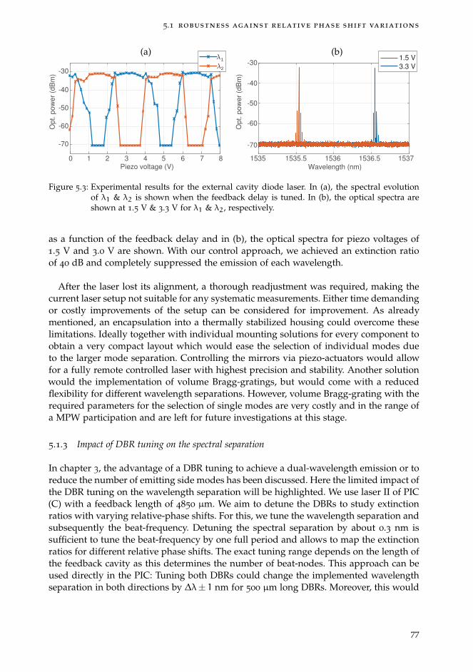
5.1 robustness against relative phase shift variations
1535 1535.5 1536 1536.5 1537
Wavelength (nm)
-70
-60
-50
-40
-30
Op
t. p
ow
er
(dB
m)
Piezo voltage (V)
-70
-60
-50
-40
-30
Op
t. p
ow
er
(dB
m)
1
2
0 1 2 3 4 5 6 7 8
1.5 V
3.3 V
(a) (b)
Figure 5.3: Experimental results for the external cavity diode laser. In (a), the spectral evolutionof λ1 & λ2 is shown when the feedback delay is tuned. In (b), the optical spectra areshown at 1.5 V & 3.3 V for λ1 & λ2, respectively.
as a function of the feedback delay and in (b), the optical spectra for piezo voltages of1.5 V and 3.0 V are shown. With our control approach, we achieved an extinction ratioof 40 dB and completely suppressed the emission of each wavelength.
After the laser lost its alignment, a thorough readjustment was required, making thecurrent laser setup not suitable for any systematic measurements. Either time demandingor costly improvements of the setup can be considered for improvement. As alreadymentioned, an encapsulation into a thermally stabilized housing could overcome theselimitations. Ideally together with individual mounting solutions for every component toobtain a very compact layout which would ease the selection of individual modes dueto the larger mode separation. Controlling the mirrors via piezo-actuators would allowfor a fully remote controlled laser with highest precision and stability. Another solutionwould the implementation of volume Bragg-gratings, but would come with a reducedflexibility for different wavelength separations. However, volume Bragg-grating with therequired parameters for the selection of single modes are very costly and in the range ofa MPW participation and are left for future investigations at this stage.
5.1.3 Impact of DBR tuning on the spectral separation
In chapter 3, the advantage of a DBR tuning to achieve a dual-wavelength emission or toreduce the number of emitting side modes has been discussed. Here the limited impact ofthe DBR tuning on the wavelength separation will be highlighted. We use laser II of PIC(C) with a feedback length of 4850 µm. We aim to detune the DBRs to study extinctionratios with varying relative-phase shifts. For this, we tune the wavelength separation andsubsequently the beat-frequency. Detuning the spectral separation by about 0.3 nm issufficient to tune the beat-frequency by one full period and allows to map the extinctionratios for different relative phase shifts. The exact tuning range depends on the length ofthe feedback cavity as this determines the number of beat-nodes. This approach can beused directly in the PIC: Tuning both DBRs could change the implemented wavelengthseparation in both directions by ∆λ± 1 nm for 500 µm long DBRs. Moreover, this would
77
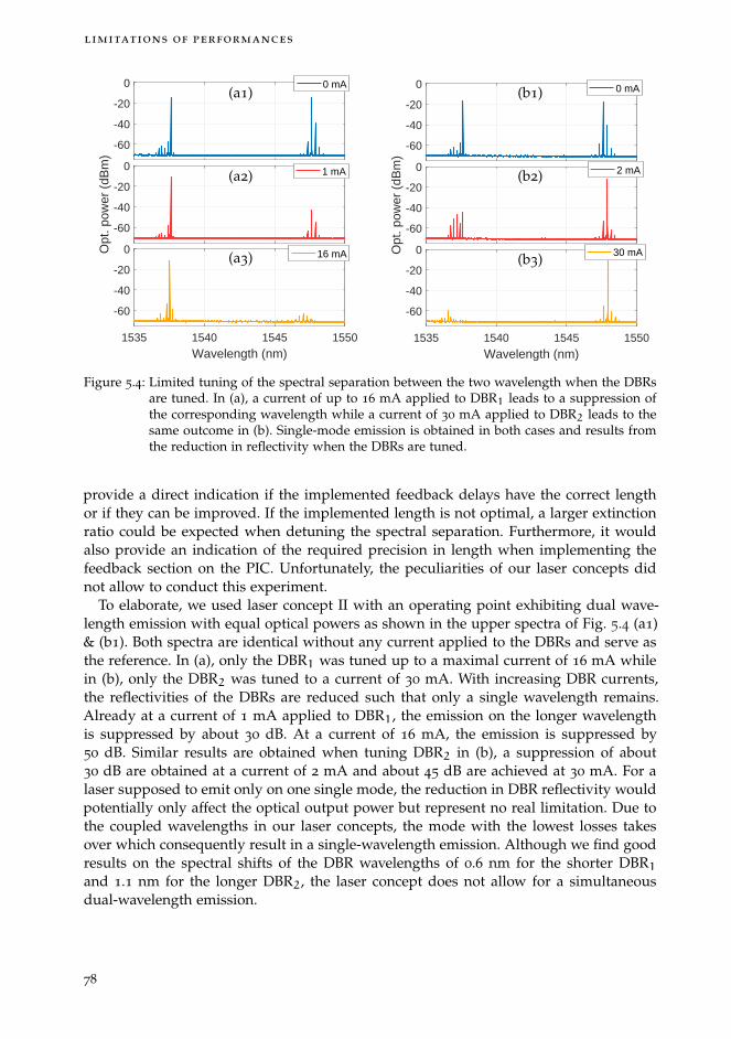
limitations of performances
-60
-40
-20
0 0 mA
-60
-40
-20
0
Opt
. pow
er (
dBm
)
1 mA
1535 1540 1545 1550
Wavelength (nm)
-60
-40
-20
0 16 mA
(a1)
(a2)
(a3)
-60
-40
-20
0 0 mA
-60
-40
-20
0
Opt
. pow
er (
dBm
)
2 mA
1535 1540 1545 1550
Wavelength (nm)
-60
-40
-20
0 30 mA
(b1)
(b2)
(b3)
Figure 5.4: Limited tuning of the spectral separation between the two wavelength when the DBRsare tuned. In (a), a current of up to 16 mA applied to DBR1 leads to a suppression ofthe corresponding wavelength while a current of 30 mA applied to DBR2 leads to thesame outcome in (b). Single-mode emission is obtained in both cases and results fromthe reduction in reflectivity when the DBRs are tuned.
provide a direct indication if the implemented feedback delays have the correct lengthor if they can be improved. If the implemented length is not optimal, a larger extinctionratio could be expected when detuning the spectral separation. Furthermore, it wouldalso provide an indication of the required precision in length when implementing thefeedback section on the PIC. Unfortunately, the peculiarities of our laser concepts didnot allow to conduct this experiment.
To elaborate, we used laser concept II with an operating point exhibiting dual wave-length emission with equal optical powers as shown in the upper spectra of Fig. 5.4 (a1)& (b1). Both spectra are identical without any current applied to the DBRs and serve asthe reference. In (a), only the DBR1 was tuned up to a maximal current of 16 mA whilein (b), only the DBR2 was tuned to a current of 30 mA. With increasing DBR currents,the reflectivities of the DBRs are reduced such that only a single wavelength remains.Already at a current of 1 mA applied to DBR1, the emission on the longer wavelengthis suppressed by about 30 dB. At a current of 16 mA, the emission is suppressed by50 dB. Similar results are obtained when tuning DBR2 in (b), a suppression of about30 dB are obtained at a current of 2 mA and about 45 dB are achieved at 30 mA. For alaser supposed to emit only on one single mode, the reduction in DBR reflectivity wouldpotentially only affect the optical output power but represent no real limitation. Due tothe coupled wavelengths in our laser concepts, the mode with the lowest losses takesover which consequently result in a single-wavelength emission. Although we find goodresults on the spectral shifts of the DBR wavelengths of 0.6 nm for the shorter DBR1and 1.1 nm for the longer DBR2, the laser concept does not allow for a simultaneousdual-wavelength emission.
78

5.1 robustness against relative phase shift variations
Nevertheless, it is possible to compensate for the suppressed wavelength by also tun-ing the second DBR. Tuning both DBRs results in a reduction in reflectivity for both ofthem and simultaneous dual-wavelength emission is maintained. In particular, the dual-wavelength emission for the spectrum shown in (a3) with 16 mA applied to DBR1 canbe restored by increasing the current of DBR2 to about 15 mA. Although this results ina spectral shift for both DBRs to shorter wavelengths, it does not change the spectralseparation significantly. Hence, applying DBR currents for the purpose of changing thespectral separation has been avoided as this is also adds heat to the system. The DBRshave only been tuned to either achieve a simultaneous dual-wavelength emission when-ever a single-wavelength emission occurred, or to suppress the emission of undesiredside modes as the bandwidth is reduced as well. About 8 mA would have been requiredto either tune DBR1 or DBR2 to achieve the required change in spectral separation of0.3 nm. As this was not feasible in our laser concepts, we left these studies for futurework.
79
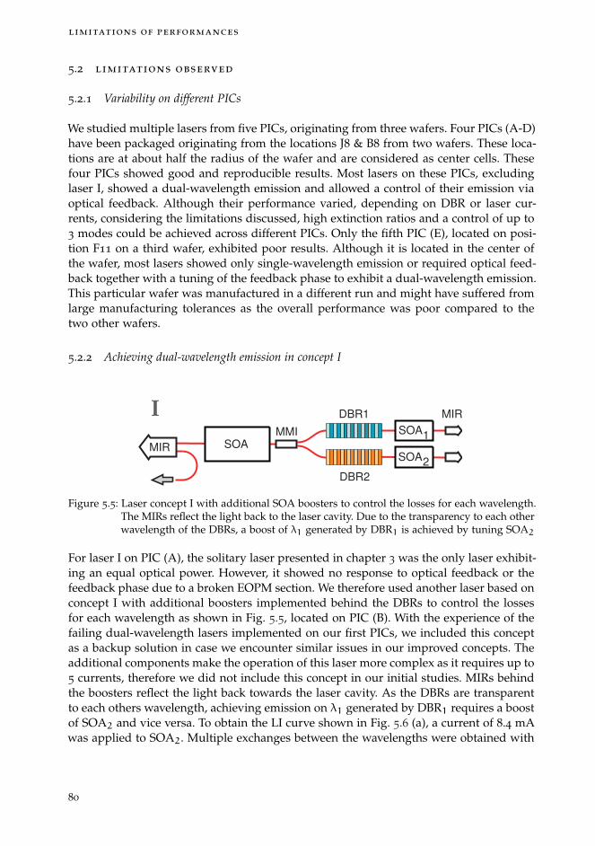
limitations of performances
5.2 limitations observed
5.2.1 Variability on different PICs
We studied multiple lasers from five PICs, originating from three wafers. Four PICs (A-D)have been packaged originating from the locations J8 & B8 from two wafers. These loca-tions are at about half the radius of the wafer and are considered as center cells. Thesefour PICs showed good and reproducible results. Most lasers on these PICs, excludinglaser I, showed a dual-wavelength emission and allowed a control of their emission viaoptical feedback. Although their performance varied, depending on DBR or laser cur-rents, considering the limitations discussed, high extinction ratios and a control of up to3 modes could be achieved across different PICs. Only the fifth PIC (E), located on posi-tion F11 on a third wafer, exhibited poor results. Although it is located in the center ofthe wafer, most lasers showed only single-wavelength emission or required optical feed-back together with a tuning of the feedback phase to exhibit a dual-wavelength emission.This particular wafer was manufactured in a different run and might have suffered fromlarge manufacturing tolerances as the overall performance was poor compared to thetwo other wafers.
5.2.2 Achieving dual-wavelength emission in concept I
DBR1
DBR2
MMI
MIR SOA
MIRI
SOA
SOA1
2
Figure 5.5: Laser concept I with additional SOA boosters to control the losses for each wavelength.The MIRs reflect the light back to the laser cavity. Due to the transparency to each otherwavelength of the DBRs, a boost of λ1 generated by DBR1 is achieved by tuning SOA2
For laser I on PIC (A), the solitary laser presented in chapter 3 was the only laser exhibit-ing an equal optical power. However, it showed no response to optical feedback or thefeedback phase due to a broken EOPM section. We therefore used another laser based onconcept I with additional boosters implemented behind the DBRs to control the lossesfor each wavelength as shown in Fig. 5.5, located on PIC (B). With the experience of thefailing dual-wavelength lasers implemented on our first PICs, we included this conceptas a backup solution in case we encounter similar issues in our improved concepts. Theadditional components make the operation of this laser more complex as it requires up to5 currents, therefore we did not include this concept in our initial studies. MIRs behindthe boosters reflect the light back towards the laser cavity. As the DBRs are transparentto each others wavelength, achieving emission on λ1 generated by DBR1 requires a boostof SOA2 and vice versa. To obtain the LI curve shown in Fig. 5.6 (a), a current of 8.4 mAwas applied to SOA2. Multiple exchanges between the wavelengths were obtained with
80
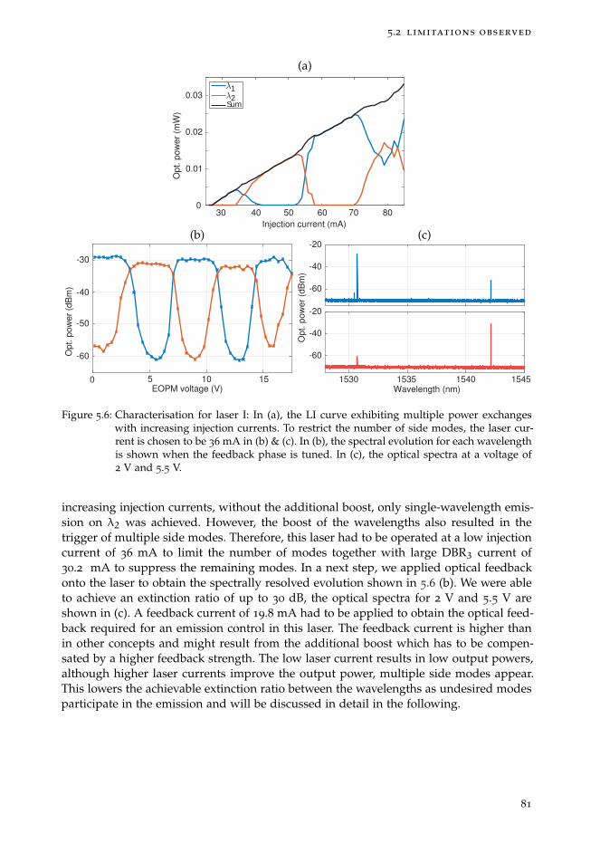
5.2 limitations observed
-60
-40
-20
1535 1540 15451530Wavelength (nm)
-60
-40
-20
Op
t. p
ow
er
(dB
m)
10 15EOPM voltage (V)
-60
-50
-40
-30
Op
t. p
ow
er
(dB
m)
50
Op
t. p
ow
er
(mW
)
12
Sum
Injection current (mA)
30 40 50 60 70 800
0.01
0.02
0.0312
Sum
(a)
(b) (c)
Figure 5.6: Characterisation for laser I: In (a), the LI curve exhibiting multiple power exchangeswith increasing injection currents. To restrict the number of side modes, the laser cur-rent is chosen to be 36 mA in (b) & (c). In (b), the spectral evolution for each wavelengthis shown when the feedback phase is tuned. In (c), the optical spectra at a voltage of2 V and 5.5 V.
increasing injection currents, without the additional boost, only single-wavelength emis-sion on λ2 was achieved. However, the boost of the wavelengths also resulted in thetrigger of multiple side modes. Therefore, this laser had to be operated at a low injectioncurrent of 36 mA to limit the number of modes together with large DBR3 current of30.2 mA to suppress the remaining modes. In a next step, we applied optical feedbackonto the laser to obtain the spectrally resolved evolution shown in 5.6 (b). We were ableto achieve an extinction ratio of up to 30 dB, the optical spectra for 2 V and 5.5 V areshown in (c). A feedback current of 19.8 mA had to be applied to obtain the optical feed-back required for an emission control in this laser. The feedback current is higher thanin other concepts and might result from the additional boost which has to be compen-sated by a higher feedback strength. The low laser current results in low output powers,although higher laser currents improve the output power, multiple side modes appear.This lowers the achievable extinction ratio between the wavelengths as undesired modesparticipate in the emission and will be discussed in detail in the following.
81

limitations of performances
10 12 14 16
EOPM voltage (V)
-45
-40
-35
-30
-25
-20
-15
-10O
pt. p
ow
er
(dB
m)
1
2
-60
-40
-20
0
1535 1540 1545 1550
Wavelength (nm)
-60
-40
-20
0
Op
t. p
ow
er
(dB
m)
-50
-40
-30
-20
-10
Op
t. p
ow
er
(dB
m)
1a
1b
Sum
2a
2b
2c
Sum
86420
10 12 14 16
EOPM voltage (V)
86420 10 12 14 16
EOPM voltage (V)
86420
-60
-50
-40
-30
-20
-10
Op
t. p
ow
er
(dB
m)
-60
1a 1b
2a
2b
2c
(a) (b)
(c) (d)
Figure 5.7: In (a), the limited suppression ratio of the two wavelength regions λ1 & λ2 is shown.The origin is the appearance of multiple side-modes shown in (b). In (c) & (d), theevolution and the energy exchange between the individual modes is shown. Tuning thefeedback phase results in the undesired selection of the side-modes which hampers thesuppression ratio.
5.2.3 Longitudinal modes
In this section, we will discuss the negative impact that neighbouring longitudinal modescan have on the proposed control approach. In some of the dual-wavelength lasers basedon an MIR, i.e. laser concepts I & II, the selectivity of the DBRs is not sufficient to selectone individual mode. Either multiple modes emit at once or a sequential selection ofdifferent modes occurs if the laser current or the EOPM voltage is tuned. Applying acurrent to the DBRs can counteract this behaviour as discussed in chapter 3. Here weuse a laser concept II with a feedback cavity length of 4850 µm from PIC (A), whichshowed an emission on up to five modes and will be used to demonstrate the interactionbetween the modes when the EOPM voltage is tuned. In Fig. 5.7 (a), the spectral evolu-tion of the two wavelength regions are shown in red and blue, i.e. for each wavelengthregion λ1 & λ2, the emitting modes were summed up to achieve this result. In (b), theoptical spectra at an EOPM voltage of 3.2 V and 14 V are shown, showing all five emit-ting modes indicated by λ1a to λ2c. The wavelength region of 1537 nm comprises of twomodes λ1a & λ1b exchanging their energy depending of the EOPM voltage. This can beseen in (c), where the individual modes are plotted together with their sum, correspond-
82

5.2 limitations observed
ing to λ1 in (a). It is visible that λ1b is the dominant mode, emitting for most of theEOPM voltages. However, around 2-4 V, 8 V and between 10-12 V, λ1a shows a parasiticemission whenever λ1b is turned on or off. As both modes can still be suppressed atthe same time, the disturbance is limited to a small voltage range. For the wavelengthregion around 1547 nm shown in (d), three modes compete about the available gain andcan not all be suppressed at the same time. While λ2c seems to dominate the emissionfor most of the EOPM voltages with λ2a & λ2b being suppressed by up to 40 dB, whenλ2c is suppressed, the remaining modes take over the emission. Although the individ-ual modes can be suppressed to a large degree, their sum shows only a modulation ofabout 10 dB. We find that the less modes are involved into the emission, the better ourcontrol capabilities are, resulting in higher suppression ratios and also in full switchesbetween the wavelengths. The reduction of emitting modes to a minimum has also beenpointed out in previous work on quantum-dot lasers [48] and was identified as a cru-cial parameter for this work. The emergence of multiple modes can be circumvented byeither reducing the gain current and subsequently the available gain, or by tuning theDBR currents. However, this restricts our lasers to a small operation range and suggestsan improvement of the DBR selectivities.
5.2.4 Transient dynamics for switching
0 100 200 300 400 500 600Time (ns)
-0.2
0
0.2
0.4
0.6
0.8
1
1.2
Am
plit
ud
e (
a.u
.)
1
Trigger2
-10 10 20 30 40 50Time (ns)
-0.2
0
0.2
0.4
0.6
0.8
1
1.2
Am
plit
ud
e (
a.u
.)
0
1
Trigger2
Figure 5.8: Transient behaviour with multiple switches between the two wavelengths λ1 & λ2 inred and blue, respectively, before reaching a stable state. The switch is initiated withthe trigger signal shown in black and indicated by the dotted line.
In chapter 4 the switching performances with switching times of a few nano-secondshave been demonstrated. However, these excellent performances are not observed for alllasers and operating conditions. In some cases, we observed that the laser could exhibitlong transients with several switches between λ1 & λ2 before reaching a stable state. Atypical example is shown in Fig. 5.8 (a) & (b) for laser III from PIC (B) with two differ-ent time scales. The reaction time for λ1 to initiate the switch is about 1 ns, visible in (a),however, it only exhibits a partial switch between 0 and 32 ns. Within this time, λ2 showsno reaction. Only after 32 ns a full switch between both wavelengths occurs. Unexpect-edly, after about 100 ns, another switch back to λ2 occurs with λ1 only being partiallysuppressed, visible in (b). These unexpected switches occur multiple times until reachingstable conditions beyond 500 ns. These switches are repetitive and do not change over
83

limitations of performances
time. The repetition times do not correspond to any round-trip lengths in the feedbackcavity or reflections due to cable length in the setup as they are in the range of tens ofmeter.
To gain more insights on this issue, we used a Fourier-Transform-Interferometer torecord time-resolved optical spectra. A special add-on for this interferometer allows toobtain the optical spectra of repetitive signals stepwise with a low nano-second timeresolution ∆t. Each trigger step n serves as a reference time t0, the optical spectrum isrecorded at different times t = t0 + n ·∆t to scan the spectral evolution over time. Thiswould have allowed us to observe the whole optical spectrum and would have givenvaluable insights on the switching dynamics and potential undesired side modes beingtriggered. Unfortunately, the dedicated control setup did not work as intended and onlyallowed for time resolutions in the µs-range. We therefore left these studies for futurework.
Moreover, the current setup is not optimized for high-frequency modulation. Althougha probe was used to bias the EOPM, the bond wires were connected to the electronicboards at all times to operate the laser and feedback SOAs. Hence, implementing anRF EOPM might overcome this limitation and could lead to a stable switch by using aGSG probe. The RF EOPM allows for a frequency bandwidth of up to 8 GHz and couldpotentially lead to even faster switching times.
84
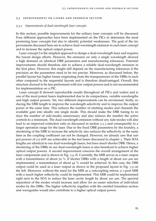
5.3 improvements on lasers and feedback section
5.3 improvements on lasers and feedback section
5.3.1 Improvements of dual-wavelength laser concepts
In this section, possible improvements for the solitary laser concepts will be discussed.Four different approaches have been implemented on the PICs to determine the mostpromising laser concepts but also to identify potential weaknesses. The goal of the im-provements discussed here are to achieve dual-wavelength emission in each laser conceptand to increase the optical output power.
Laser concept I is the simplest approach to design a dual-wavelength laser and requiresthe lowest design efforts. However, the emission on only a single wavelength showeda high demand on identical DBR parameters and manufacturing tolerances. Potentialimprovements should therefore aim to achieve a reliable dual-wavelength emission inthe first place. However, this might still depend on the manufacturing tolerances if theprecision on the parameters need to be too precise. Moreover, as discussed before, theparallel layout has higher losses originating from the transparencies of the DBRs to eachother compared to the sequential layouts and is therefore disadvantaged. Overall, thisstructure showed to be less performant with low output powers and is not recommendedfor implementation on a PIC.
Laser concept II showed reproducible results throughout all PICs and wafers and isone of the most potent lasers implemented due to its compactness, variable wavelengthsand high output powers. Yet, two different improvements can be envisioned, firstly, re-ducing the DBR length to improve the wavelength selectivity and to improve the outputpower at the same time. This reduces the number of emitting modes and channels theavailable gain into ideally one single mode. This should make the DBR tuning to re-duce the number of side-modes unnecessary and also reduces the number the activecontrols to a minimum. The dual-wavelength emission without any side-modes will alsolead to an improved extinction ratio as discussed in section 5.2.3 and consequently to alarger operation range for the laser. Due to the fixed DBR parameters by the foundry, ashortening of the DBR to increase the selectivity also reduces the reflectivity at the sametime as the coupling coefficient can not be changed. However, we already saw that out-put powers of 2.2 mW are achievable in the test lasers discussed in chapter 3. Their SOAlengths are identical to our dual-wavelength lasers, but have much shorter DBR. Hence, ashortening of the DBRs in our dual-wavelength lasers is also beneficial to achieve higheroptical output powers. A second improvement concerns the overall arrangement of thelaser components and is shown in Fig. 5.9, II. Currently, the MIR serves as a laser outputwith a transmittance of about 50 %. If shorter DBRs with a length of about 200 µm areimplemented, a transmittance of about 42 % would be achieved. In this case, the DBRoutput could be used as a laser output as shown in the proposed layout in Fig. 5.9 onthe left. Moreover, without the need for the MIR as a outcoupling mirror, a 1-port MIRwith a much higher reflectivity could be implemented. This MIR could be implementedright next to the SOA to reduce the laser cavity length by about 300 µm. The spectralseparation of the modes would increase and allow for an easier selection of individualmodes by the DBRs. The higher reflectivity together with the omitted transition sectionand waveguides would also contribute to a higher optical output power.
85
limitations of performances
Figure 5.9: Proposed improvements for laser concept II & III. In II, a 1-port MIR closes the cavitywhich improves optical output power. Shorter lengths for DBR1 & DBR2 to improvewavelength selectivity, also allow the use as an optical output. In III, the feedback couldbe applied to the output of DBR1 & DBR2 to reduce the footprint to a minimum. Thiswould also improve the output power via DBR3 as no MMI-splitter is required to applythe feedback.
Laser concept III also showed reproducible results throughout all PICs and waferswith the highest extinction ratios and a control of up to three wavelengths. The opticalpowers are the highest achieved and might result from the shorter DBRs implemented.This is a good indication that other laser concepts could benefit from shorter DBRs toimprove their output power. Nevertheless, in the design stage described in chapter 3,an equal optical power was favoured over a maximal power, leaving room for potentialincrease in optical power for future designs, i.e. circuit simulations could be performedwith the goal of maximizing the optical power. For testing purposes, 0.3 nm detunedDBRs compared to the optimal results from the simulations have been implementedto achieve a large range of wavelength separations. This could be neglected in futuredesigns to reduce the number of active control parameters and to ease the use for thelaser operation. Moreover, for this particular concept, a much more compact layout couldbe implemented as shown in Fig. 5.9, III. Due to the transmittance of DBR1 & DBR2of 42 % & 11 %, the feedback section could be implemented behind these two DBRs.The resulting feedback strength with about 5 % would be much stronger, but could becontrolled with the SOA. This arrangement would be much more compact and coulddiscard the MMI splitter in the current feedback section, hence improving the opticaloutput power as well.
The parallel arrangement of the DBRs in laser concept IV performed well. Comparingit to the poor performing concept I, the active control of the DBR overlaps allowed tocompensate for potential losses to achieve a dual-wavelength emission. Combining theoutputs of the two DBRs was intended to improve of the optical power resulting from theparallel DBR arrangement, however has a major design flaw. The mutual transparencyof the DBRs allows the feedback to fully enter the laser cavity. If the laser is emittingon the wavelength generated of DBR1, the light is emitted through DBR2 and vice versa.This also applies to the optical feedback phase. However, if the optical path lengths arenot identical, different phases will be reflected into the laser cavity which can result inundesired dynamics. Different optical path lengths are highly possible, either due tomanufacturing tolerances or due to different refractive indices due to different imple-mented DBR wavelength. To avoid this, the parallel outputs should not be combinedand neither used as an optical output, nor to control the feedback strength. Neverthe-less, this is the only laser concept capable of emitting simultaneously from two differentwavelengths with a 1 nm separation as laser concept III only showed sequential emission.
86
5.3 improvements on lasers and feedback section
Hence, shortening DBR3 and using it as an outcoupling mirror could lead to a promisinglaser source. However, also with the drawback of lower optical output powers due to theparallel DBR arrangement.
5.3.2 Optimization of the optical feedback cavity
We were able to demonstrate a dual wavelength control in all laser concepts. For allof these demonstrators, we implemented very long EOPM sections of 1200 µm into allof our feedback sections for research purposes. This allowed for multiple wavelengthswitches corresponding to feedback delays of up to 4π at the highest EOPM voltages.However, in practice a phase shift of π is sufficient to switch between two wavelengthsonce, hence, with a design voltage of 8 V, an EOPM length of 600 µm is sufficient. Con-sidering the feedback strength required to achieve a full switch, the feedback SOAs wereoperated in the range of 10 mA. Hence, a shorter feedback SOA with a length around100 µm would be sufficient to achieve the same feedback strength. Potentially the activecontrol of the feedback SOA could be avoided once the optimal feedback strength isdetermined. This could be achieved in two ways, either in designing a customized MMIsplitter to provide the optimal feedback strength, while also increasing the output powerof the laser at the same time. However, this is connected to a large design effort as nopredefined building blocks exist at this point. A simpler approach would be to includethe ideal feedback SOA length to achieve the desired feedback strength without biasing,i.e. adding the right amount of losses for the feedback cavity.
Shortening the SOA and EOPM section would reduce the minimal required lengthfor all components from 2400 µm to about 1600 µm, i.e. the feedback section can notbe shorter than this. For a 1 nm wavelength separation, the optimal feedback lengthis multiples of about 700 µm, corresponding to the distance of one node of the beat-frequency to another. Hence, the feedback length could be reduced to about 1750 µm.For a 10 nm separation the distance between the nodes is about 70 µm which allowsfor a reduction of the feedback section to about 1645 µm. This is a significant reductionin footprint by a factor of about 1.8. Moreover, a shorter cavity is more robust againstdynamical behaviours and allows for larger injection currents and faster switching timesas discussed in the simulations in chapter 2. However, the precise length of the feedbacksection has to be adapted to the expected wavelength for each laser individually. Thisapplies in particular for laser concepts III & IV where the overlapping DBRs define theemitting wavelengths and have to be determined by simulations.
87

limitations of performances
5.4 conclusion
To conclude, in this chapter we highlighted several limitations of our lasers and the feed-back control. In the beginning, we highlighted the open question on how the extinctionratio scales with varying spectral separation and suboptimal feedback phases to evalu-ate the limitations of the control approach. To get further insights on this, we presentedexperimental work using a discrete device, an external cavity diode laser as well as theDBR tuning of our dual-wavelength lasers. However, performance and stabilisation is-sues limited these studies and are therefore left for future work. Nevertheless, we wereable to get additional insight on the limited tuning capability of the spectral separationsbetween the wavelengths. Tuning one DBR results in a single-wavelength emission dueto the reduction in reflectivity of the DBR whereas a tuning of both DBRs results in ashift of both wavelengths to shorter wavelengths while maintaining the spectral separa-tion. Another limitation is the appearance of undesired side modes which hampers theperformance, limits the extinction ratios and requires improvements on the selectivityof the DBRs. Overall we experienced dynamics very rarely , however, when investigat-ing the switching speed we found unexpected switches in some lasers before reachinga stable state. This might be possible to prevent by optimizing the feedback section to-wards an RF compatible system. Finally, we discussed and proposed improvements forthe most promising laser concepts and the feedback section. Whereas improvements forthe feedback section aimed to reduce the footprint, the improvements for the lasers aremore comprehensive and aim to improve the general performance with more compactdevices and less control parameters for a successful next MPW participation.
88

6 C O N C L U S I O N
In this final chapter, we will summarize the essential points of this thesis and high-light the main achievements. We proposed a new technique to shape the emission of adual-wavelength laser based on a phase controlled optical feedback approach. To demon-strate this approach, we designed custom dual-wavelength lasers and implemented themtogether with our control approach successfully onto a PIC. We demonstrated high per-formances with this proof of concept and achieved extinction ratios of up to 50 dB withswitching times below 4 ns. In the first section 6.1 we will recapitulate the goal andachievements made in each chapter. Finally, in the second section 6.2 we will draw pos-sible perspectives for future work.
89
conclusion
6.1 main achievements
In the second chapter, we highlighted the fundamental working principle of the controlapproach.
• First, we presented the approach to control the amplitudes of two different wave-lengths using a phase controlled optical feedback. The underlying idea is to achievea relative phase shift of π between the wavelengths after a full round trip in thefeedback cavity. This way, one wavelength is in phase and will benefit from an ex-tra boost while the other wavelength is out of phase and suffers from extra losses.Detuning the feedback cavity on the wavelength scale changes the round-trip timein favour of the suppressed wavelength to achieve a switch.
• Then, we introduced the simulation model to obtain the best parameters to imple-ment an optimal feedback cavity onto a PIC. We studied the phase space given bythe two wavelengths and highlighted that a switch is possible for a large range ofrelative phase shifts and that even suboptimal conditions allow a full control overthe laser emission. Moreover, we discussed that the control approach is dependenton intrinsic laser parameter like the coupling coefficient β and the gain differencesbetween the two wavelengths. Then, we showed that the optical feedback strengthis a crucial parameter and emphasized that it allows to actively compensate for pos-sible bad intrinsic laser parameters appearing in a manufactured laser to achieve afull control. Furthermore, we also identified a short feedback cavity to be beneficialas it leads to the fastest switching times.
In the third chapter, we presented different solitary dual-wavelength laser concepts, dis-cussed the design and optimization process and presented their characteristics.
• First, we presented four different laser concepts with varying spectral separationsand optimized them using a circuit simulator. We optimized each concept for anequal optical power as well as for a high side mode suppression ratio. We also de-termined the exact wavelengths each laser will emit on as this is a crucial parameterfor the implementation of corresponding feedback cavities.
• Second, we characterized each laser concept and discussed their peculiarities: Wedemonstrated a dual-wavelength emission in all concepts. However, we also iden-tified the concepts II & III to perform the best across different PICs and wafers asthey showed to be the most reliable sources with the highest optical output powers.
• At last, we characterized DBRs under varying currents and temperatures and con-nected the observed effects to three different behaviours in our lasers. First weobserved a shift to shorter wavelengths, which was to be expected. The second ef-fect was a reduction in the spectral width by about 0.3 nm and the third effect wasa reduction in reflectivity by 1.2 dB. The two latter effects were unexpected but onthe one hand we exploited them to trigger dual-wavelength emission or to limit thenumber of emitting side modes. On the other hand, we connected the reduction inreflectivity to our limited capability of tuning the spectral separations of the twowavelengths.
90

6.1 main achievements
In the fourth chapter, we discussed the design of the optical feedback cavity and pre-sented experimental results on the tuning of the feedback phase.
• First, we discussed the layout of the feedback cavity and implemented individualfeedback cavities for each laser. We implemented an identical arrangement withan SOA and an EOPM for each of them and adapted the feedback cavities byvariations in the waveguide lengths.
• Second, we presented and discussed the control of two as well as three wavelengthsby tuning the optical feedback phase via the EOPM. We demonstrated extinctionratios of up to 35 dB for lasers with a 10 nm separation and even higher extinctionratios of 50 dB for lasers with a 1 nm separation. We highlighted that the repetitiveswitching cycles correspond to a 4π phase shift. Hence, we could confirm the un-derlying control mechanism to be the expected phase dependent loss modulations.
• Then, we explored the switching performance for different laser and feedback cur-rents and mapped their parameter space. We found that adapting the feedbackstrength enables for full switches for a large laser current range. However, the cur-rent limitations on the laser concepts prevent us form efficiently operating the laserfor most set of parameters.
• At last, we investigated the switching speed and obtained switching times of 3.5 nswith a non-optimized setup. These excellent results show that the feedback basedcontrol approach is capable of reaching very fast and competitive switching timesand could reach even faster switching considering a dedicated RF-setup.
In the last chapter, we identified different limitations of our laser concepts and proposedseveral improvements.
• First, we aimed to demonstrate our control approach using either a quantum-dotlaser or an external cavity diode laser and to benefit from the flexibility of their ex-ternal feedback arrangement. We conducted these experiments with the intentionto identify possible limitations of our control approach by studying different wave-length separations as well as different feedback phase shifts. Although we obtaineda 40 dB extinction ratio in the external cavity diode laser, limited performance ofboth sources did not allow for these studies and we therefore left them for futurework.
• We then studied the impact of the DBR tuning onto the spectral separation of thedual-wavelength laser. We showed that a DBR tuning lowers the DBR reflectivitywhich results in a single wavelength emission and severely limits the flexibility ofour lasers.
• Moreover, we emphasized that a multi-modes emission has a major impact on themaximal extinction ratios. We showed that an energy exchanges between differentmodes appear as each of them experiences different feedback phases. We connectedthis to a low wavelength selectivity of the DBR which can be improved by a short-ening of the DBR lengths.
91

conclusion
• Next, to overcome the weaknesses identified, we proposed different improvementsto enhance the performance, reliability and compactness towards advanced lasersources. We identified shorter DBRs to be beneficial to improve output powers andthe wavelength selectivity.
• At last, we identified potential improvements also for the external feedback cavity.First, we proposed a GSG connection to avoid the spurious signals discussed andto benefit from the fast electro-optic effect to reach highest switching speeds. Then,we proposed a reduction of the feedback SOA and EOPM lengths to achieve themost compact control approach. Moreover, implementing an optimal length for thefeedback SOA could provide the precise feedback strength for a passive SOA andthus, could reduce the control parameter to just a single voltage for the EOPM.
92
6.2 perspectives for future work
6.2 perspectives for future work
The photonic integration technology is constantly growing and mainly driven by telecom-munication applications. The higher demand on PICs and the further development to-wards standardized electrical and optical connections lowers the costs and PICs becomemore appealing for customers in other branches. Applications in the medical technolo-gies like optical coherence tomography, measurement tasks like fibre or gas sensing,image processing like LIDAR for drones and self-driving cars and spectrometers foragriculture to analyse the condition of seeds, fruits and vegetables are just a few ex-amples of the current market shares [70]. The benefits of a compact, cost effective andflexible design makes this technology interesting for various applications. With the con-trol approach presented in this thesis, we hope to contribute with an compact, energyefficient and easy to use method to control the emission of multi wavelength lasers forpotential applications. The compactness of the approach allows to implement opticalsources including our control approach together with analysis devices onto one singlechip. The single control voltage and the low requirements on the EOPM voltage makesthe operation very simple.
Nevertheless, to reach a mature level of this control approach, several improvementshave to be made and open research questions still have to be answered. As alreadypointed out in chapter 5, various improvements on the lasers have to be made towardssources with high output powers and reliable two-wavelength emission. Also improve-ments have been proposed for the feedback control, first to reduce the footprint on thePIC and second to implement GSG contacts to improve the switching performance. More-over, additional test structures are required to determine the amount of feedback sendback towards the laser cavity. To get insights on these issues, a new multi-project-waferparticipation is required. In addition, a participation to a different generic foundry plat-form like HHI could be envisioned: This would allow to compare the performances andto identify what impact the foundry specificities have on the control approach. A differ-ent coupling coefficient β or a different gain spectrum and consequently different gaindifferences could be expected.
Moreover, as we have already been able to demonstrate the control of three modes,the question arises of how many mode could be controlled using one feedback cavity.The first step would be to determine a limitation on the number of modes, this could forexample be the precision on the required feedback phase to select a specific mode. Then,a major challenge would be to generation more than two uniformly separated and welldefined wavelengths to be able to implement a corresponding feedback delay length. Therequired development stages might require several MPW participations to gain enoughinsights to obtain a demonstrator. An interesting aspect is also if an asymmetric wave-length separation could be controlled, e.g. three modes with a 1 nm & 2 nm separationbetween them. This could potentially require the implementation of multiple feedbackcavities with different feedback delays to achieve the required relative phase shifts. Thechallenge would then be, to implement the different feedback cavities onto the PIC and toaddress the desired feedback cavity in practice. A simple Mach-Zehnder-Interferometerto guide the light to a particular feedback cavity would fail: These interferometers selecta specific output by achieving a precise relative phase shift in their two arms, the emis-sion of a multi-wavelength laser is therefore not compatible as each mode would require
93

conclusion
a different relative phase shift. An MMI splitter with multiple outputs to select specificcavities with additional SOA gates could be one solution. Coupling the laser light out ofthe PIC and routing the light to different feedback channels via optical fibres could beanother solution. Both options could be feasible, but would suffer from high losses.
On another note, the proposed control approach can be adapted for every platform ordual-wavelength laser with a sufficient coupling and similar gain. The implementationon the PIC provided a high thermal and mechanical stability to build a demonstrator.The limitations of the control approach could however not be determined due to thefixed components. For this, an external cavity diode laser has been presented to study thesuppression ratio under different feedback delays and different spectral separations. Thismight reveal potential limitations which could also limit the implementation for specificapplications, e.g. for very large spectral separations. To conduct these experiments, anencapsulation of the setup into a mechanically and thermally stabilized box could besuccessful.
94

L I S T O F P U B L I C AT I O N S
Some of the materials, ideas and figures in this dissertation have appeared previously inthe following publications:
publications in peer reviewed journals
1. M. Virte, R. Pawlus, M. Sciamanna, K. Panajotov, and S. Breuer, "Energy exchangebetween modes in a multimode two-color quantum dot laser with optical feedback",Optics letters, 264955, 3205-3208 (2016)
2. R. Pawlus, S. Breuer, M. Virte, "Relative intensity noise reduction in a dual-statequantum-dot laser by optical feedback", Optics Letters, Vol. 42, Issue 21, pp. 4259-4262 (2017)
3. R. Pawlus, L. L. Columbo, P. Bardella, S. Breuer, M. Gioannini, "Intensity noisebehaviour of an InAs/InGaAs quantum dot laser emitting on ground and excitedstates", Optics Letters, Vol. 43, Issue 4, pp. 867-870 (2018)
4. R. Pawlus, R. de Mey, S. Breuer, M. Virte, "Dual-wavelength lasers on genericfoundry platform", (Submitted on 14 Oct 2019), arXiv:1911.03533
patents
1. R. Pawlus, S. Breuer, H. Thienpont, M. Virte, "Wavelength control of multi-wavelengthlaser", submitted 08 Oct. 2019, Application number EP19201970.1
contributions to workshops , national and international conferences
1. R. Pawlus, M. Gioannini, M. Virte, W. Elsässer, S. Breuer, "Investigations on therelative intensity noise of a two-state quantum dot laser", Oral, SPIE PhotonicsEurope, April 2016, 9892-29, Brussels, Belgium
2. M. Virte, R. Pawlus, W. Elsässer, K. Panajotov, M. Sciamanna, and S. Breuer, "Range-dependent effects of optical feedback on multimode two-color Quantum Dot Lasers",Oral, SPIE Photonics Europe, April 2016 , 9892-31, Brussels, Belgium
3. R. Pawlus, S. Breuer, M. Virte, "Relative intensity noise reduction in a two-colorquantum-dot laser by optical feedback control", Oral, IS-PALD, Sept. 2016 , Na-tional Tsing Hua University, Hsinchu, Taiwan
4. R. Pawlus, S. Breuer, M. Virte, "Impact of optical feedback onto the relative inten-sity noise of a two-state quantum-dot laser", Oral, ESLW, Oct. 2016 , TechnischeUniversitÀt Darmstadt, Darmstadt, Germany
95
list of publications
5. R. Pawlus, S. Breuer, M. Virte, "RIN improvement by optical feedback of a two-stateemitting QD laser", Oral, IS-PALD, Nov. 2017, Paris, France
6. R. Pawlus, L. L. Columbo, P. Bardella, S. Breuer, M. Gioannini, "Intensity noiseof a two-state quantum dot laser", Poster presentation, Deutsche PhysikalischeGesellschaft e.V., March 2018, HL 13.84, Berlin, Germany
7. R. Pawlus, S. Breuer, and M. Virte, "Compact dual-wavelength lasers on InP genericfoundry platform", Oral, Conference on Lasers and Electro-Optics, June 2019, CB-9.4, Munich, Germany
8. R. Pawlus, R. de Mey, S. Breuer, M. Virte, "Impact of DBR tuning on a dual-wavelength laser implemented on a generic foundry platform", Oral, IS-PALD, Nov.2019, Metz, France
9. R. Pawlus, R. de Mey, S. Breuer, M. Virte, "Control of dual-wavelength laser usingmonolithically integrated phase-controlled optical feedback", Oral, SPIE Europe,April 2020, Strassbourg, France
supervised master thesis
1. R. de Mey, "Tailoring Two-Color Laser Emission Using an Integrated FeedbackCavity", 2019
2. M. Skënderas, "Control of a Widely-Tunable Ring Laser Based On Cascaded Asym-metric Mach-Zehnder Interferometers", 2019
96
B I B L I O G R A P H Y
[1] A. Einstein, “The Quantum Theory of Radiation,” Physikalische Zeitschrift, vol. 18,no. 121, 1917.
[2] T. Numai, Fundamentals of Semiconductor Lasers. Springer-Verlag, 2004.
[3] Z. Alferov, “Double heterostructure lasers: Early days and future perspectives,”IEEE Journal on Selected Topics in Quantum Electronics, vol. 6, no. 6, pp. 832–840, 2000.
[4] J. Carroll, J. Whiteaway, and D. Plumb, Distributed Feedback Semiconductor Lasers. TheInstitution of Electrical Engineers, London, United Kingdom, 1998.
[5] E. U. Rafailov, The Physics and Engineering of Compact Quantum Dot-based Lasers forBiophotonics. John Wiley & Sons Inc., 2014.
[6] A. Markus, J. X. Chen, C. Paranthoen, A. Fiore, C. Platz, and O. Gauthier-Lafaye, “Si-multaneous two-state lasing in quantum-dot lasers,” Applied Physics Letters, vol. 82,no. 12, pp. 1818–1820, 2003.
[7] Z. Zhang, Q. Jiang, and R. Hogg, “Simultaneous three-state lasing in quantum dotlaser at room temperature,” Electronics Letters, vol. 46, no. 16, p. 1155, 2010.
[8] S. Ummethala, T. Harter, K. Koehnle, Z. Li, S. Muehlbrandt, Y. Kutuvantavida, J. Ke-mal, P. Marin-Palomo, J. Schaefer, A. Tessmann, S. K. Garlapati, A. Bacher, L. Hahn,M. Walther, T. Zwick, S. Randel, W. Freude, and C. Koos, “THz-to-optical conver-sion in wireless communications using an ultra-broadband plasmonic modulator,”Nature Photonics, vol. 13, no. 8, pp. 519–524, 2019.
[9] T. Nagatsuma, G. Ducournau, and C. C. Renaud, “Advances in terahertz commu-nications accelerated by photonics,” Nature Publishing Group, vol. 10, no. 6, pp. 371–379, 2016.
[10] I. White, R. Penty, M. Webster, Y. J. Chai, A. Wonfor, and S. Shahkooh, “Wavelengthswitching components for future photonic networks,” IEEE Communications Maga-zine, vol. 40, no. 9, pp. 74–81, 2002.
[11] S. Latkowski, A. Hänsel, N. Bhattacharya, T. De Vries, L. Augustin, K. Williams,M. Smit, and E. Bente, “Novel Widely Tunable Monolithically Integrated LaserSource,” IEEE Photonics Journal, vol. 7, no. 6, 2015.
[12] T. Mohr, S. Breuer, G. Giuliani, and W. Elsäßer, “Two-dimensional tomographic ter-ahertz imaging by homodyne self-mixing,” Optics Express, vol. 23, no. 21, p. 27221,2015.
[13] D. M. Mittleman, “Twenty years of terahertz imaging [Invited],” Optics Express,vol. 26, no. 8, p. 9417, 2018.
97

bibliography
[14] T. F. K. Reed and E. Drive, “CW Terahertz Wave Generation By Photomixing UsingA Two-longitudinal-mode Laser Diode,” Electronics letters, vol. 33, no. 24, pp. 2039–2040, 1997.
[15] M. Tani, O. Morikawa, S. Matsuura, and M. Hangyo, “Generation of terahertz radi-ation by photomixing with dual- and multiple-mode lasers,” Semiconductor Scienceand Technology, vol. 20, no. 7, pp. 151–163, 2005.
[16] S. Hoffmann and M. R. Hofmann, “Generation of Terahertz radiation with two colorsemiconductor lasers,” Laser and Photonics Reviews, vol. 1, no. 1, pp. 44–56, 2007.
[17] M. Theurer, T. Göbel, D. Stanze, U. Troppenz, F. Soares, N. Grote, and M. Schell,“Photonic-integrated circuit for continuous-wave THz generation,” Optics Letters,vol. 38, no. 19, pp. 3724–3726, 2013.
[18] M. D. Wheeler, I. R. Lambert, and M. N. R. Ashfold, “Two-colour laser-inducedgrating spectroscopy of iodine vapour,” Chemical Physics Letters, vol. 211, no. 4-5,pp. 381–384, 1993.
[19] J. Jágerská, P. Jouy, A. Hugi, B. Tuzson, H. Looser, M. Mangold, M. Beck,L. Emmenegger, and J. Faist, “Dual-wavelength quantum cascade laser for tracegas spectroscopy,” Applied Physics Letters, vol. 105, no. 16, 2014.
[20] J. Jágerská, P. Jouy, B. Tuzson, H. Looser, M. Mangold, P. Soltic, A. Hugi, R. Brönni-mann, J. Faist, and L. Emmenegger, “Simultaneous measurement of NO and NO_2
by dual-wavelength quantum cascade laser spectroscopy,” Optics Express, vol. 23,no. 2, p. 1512, 2015.
[21] M. Majumder, T. K. Gangopadhyay, A. K. Chakraborty, K. Dasgupta, and D. K.Bhattacharya, “Fibre Bragg gratings in structural health monitoring-Present statusand applications,” Sensors and Actuators A - Physical, vol. 147, no. 1, pp. 150–164,2008.
[22] U. Nawrot, T. Geernaert, B. De Pauw, D. Anastasopoulos, E. Reynders, G. De Roeck,and F. Berghmans, “Development of a mechanical strain amplifying transducer withBragg grating sensor for low-amplitude strain sensing,” Smart Materials and Struc-tures, vol. 26, no. 7, p. 75006, 2017.
[23] S. Hancock, P. Lewis, M. Foster, M. Disney, and J. P. Muller, “Measuring forests withdual wavelength lidar: A simulation study over topography,” Agricultural and ForestMeteorology, vol. 161, pp. 123–133, 2012.
[24] E. S. Douglas, J. Martel, Z. Li, G. Howe, K. Hewawasam, R. A. Marshall, C. L. Schaaf,T. A. Cook, G. J. Newnham, A. Strahler, and S. Chakrabarti, “Finding leaves inthe forest: The dual-wavelength Echidna lidar,” IEEE Geoscience and Remote SensingLetters, vol. 12, no. 4, pp. 776–780, 2015.
[25] M. Gioannini, M. Dommermuth, L. Drzewietzki, I. Krestnikov, D. Livshits,M. Krakowski, and S. Breuer, “Two-state semiconductor laser self-mixing velocime-try exploiting coupled quantum-dot emission-states: experiment, simulation andtheory,” Optics Express, vol. 22, no. 19, p. 23402, 2014.
98
bibliography
[26] B. Mason, G. A. Fish, S. P. DenBaars, and L. A. Coldren, “Widely tunable sam-pled grating DBR laser with integrated electroabsorption modulator,” IEEE Photon-ics Technology Letters, vol. 11, no. 6, pp. 638–640, 1999.
[27] M. Nakao, K. Sato, T. Nishida, and T. Tamamura, “Distributed Feedback Laser Ar-rays Fabricated by Synchrotron Orbital Radiation Lithography,” IEEE Journal on Se-lected Areas in Communications, vol. 8, no. 6, pp. 1178–1182, 1990.
[28] J. Huang, C. Sun, B. Xiong, and Y. Luo, “Y-branch integrated dual wavelengthlaser diode for microwave generation by sideband injection locking,” Optics Express,vol. 17, no. 23, pp. 20727–20734, 2009.
[29] S. D. Roh, T. S. Yeoh, R. B. Swint, A. E. Huber, C. Y. Woo, J. S. Hughes, and J. J. Cole-man, “Dual-Wavelength InGaAs-GaAs Ridge Waveguide Distributed Bragg Reflec-tor Lasers with Tunable Mode Separation,” IEEE Photonics Technology Letters, vol. 12,no. 10, pp. 1307–1309, 2000.
[30] A. Hurtado, M. Nami, I. D. Henning, M. J. Adams, and L. F. Lester, “Two-wavelength switching with a 1310-nm quantum dot distributed feedback laser,”IEEE Journal on Selected Topics in Quantum Electronics, vol. 19, no. 4, 2013.
[31] S. Hoffmann, M. Hofmann, M. Kira, and S. W. Koch, “Two-colour diode lasers forgeneration of THz radiation,” Semiconductor Science and Technology, vol. 20, no. 7,pp. 205–210, 2005.
[32] J. W. Wu, B. Nakarmi, T. Q. Hoai, and Y. H. Won, “Tunable two-color lasing emissionbased on fabry-perot laser diode combined with external cavity feedback,” IEEEPhotonics Journal, vol. 5, no. 1, 2013.
[33] C. C. Huang, C. H. Cheng, Y. S. Su, and C. F. Lin, “174-nm Mode Spacing in Dual-Wavelength Semiconductor Laser Using Nonidentical InGaAsP Quantum Wells,”IEEE Photonics Technology Letters, vol. 16, no. 2, pp. 371–373, 2004.
[34] M. L. Osowski, R. M. Lammert, and J. J. Coleman, “A dual-wavelength source withmonolithically integrated electroabsorption modulators and Y-junction coupler byselective-area MOCVD,” IEEE Photonics Technology Letters, vol. 9, no. 2, pp. 158–160,1997.
[35] J. H. Teng, S. J. Chua, Z. H. Zhang, Y. H. Huang, G. Li, and Z. J. Wang, “Dual-Wavelength Laser Source Monolithically Integrated with Y-Junction Coupler andIsolator Using Quantum-Well Intermixing,” IEEE Photonics Technology Letters, vol. 12,no. 10, pp. 1310–1312, 2000.
[36] M. Brunner, K. Gulden, R. Hövel, M. Moser, J. F. Carlin, R. P. Stanley, and M. Ilegems,“Continuous-Wave Dual-Wavelength Lasing in a Two-Section Vertical-Cavity Laser,”IEEE Photonics Technology Letters, vol. 12, no. 10, pp. 1316–1318, 2000.
[37] S. D. Roh, R. B. Swint, A. M. Jones, T. S. Yeoh, A. E. Huber, J. S. Hughes, and J. J.Coleman, “Dual-wavelength asymmetric cladding InGaAs-GaAs ridge waveguidedistributed bragg reflector lasers,” IEEE Photonics Technology Letters, vol. 11, no. 1,pp. 15–17, 1999.
99

bibliography
[38] H. Zhao, Y. Zhu, F. Li, and Y. Yu, “Wavelength bistability based on optical injectionin a novel tunable dual mode laser,” Optics Express, vol. 24, no. 4, p. 3817, 2016.
[39] M. Gioannini, “Ground-state power quenching in two-state lasing quantum dotlasers,” Journal of Applied Physics, vol. 111, no. 4, p. 43108, 2012.
[40] A. Markus, M. Rossetti, V. Calligari, D. Chek-Al-Kar, J. X. Chen, A. Fiore, andR. Scollo, “Two-state switching and dynamics in quantum dot two-section lasers,”Journal of Applied Physics, vol. 100, no. 11, p. 113104, 2006.
[41] H.-Y. Wang, H.-C. Cheng, S.-D. Lin, and C.-P. Lee, “Wavelength switching transitionin quantum dot lasers,” Applied Physics Letters, vol. 90, no. 8, p. 081112, 2007.
[42] N. A. Naderi, F. Grillot, K. Yang, J. B. Wright, A. Gin, and L. F. Lester, “Two-colormulti-section quantum dot distributed feedback laser,” Optics Express, vol. 18, no. 26,p. 27028, 2010.
[43] S. Breuer, M. Rossetti, L. Drzewietzki, I. Montrosset, M. Krakowski, M. Hopkinson,and W. Elsässer, “Dual-state absorber-photocurrent characteristics and bistability oftwo-section quantum-dot lasers,” IEEE Journal on Selected Topics in Quantum Electron-ics, vol. 19, no. 5, pp. 1–9, 2013.
[44] J. Lee and D. Lee, “Double-state lasing from semiconductor quantum dot laserdiodes caused by slow carrier relaxation,” J. Korean Phys. Soc., vol. 58, p. 239, 2011.
[45] R. Pawlus, L. L. Columbo, P. Bardella, S. Breuer, and M. Gioannini, “Intensity noisebehavior of an InAs/InGaAs quantum dot laser emitting on ground states and ex-cited states,” Optics Letters, vol. 43, no. 4, p. 867, 2018.
[46] A. Kovsh, I. Krestnikov, D. Livshits, S. Mikhrin, J. Weimert, and A. Zhukov, “Quan-tum dot laser with 75nm broad spectrum of emission,” Optics Letters, vol. 32, no. 7,pp. 793–795, 2007.
[47] M. Virte, S. Breuer, M. Sciamanna, and K. Panajotov, “Switching between groundand excited states by optical feedback in a quantum dot laser diode,” Applied PhysicsLetters, vol. 105, no. 12, p. 121109, 2014.
[48] M. Virte, R. Pawlus, M. Sciamanna, K. Panajotov, and S. Breuer, “Energy exchangebetween modes in a multimode two-color quantum dot laser with optical feedback,”Optics Letters, vol. 41, no. 14, p. 3205, 2016.
[49] M. Smit, X. Leijtens, H. Ambrosius, E. Bente, J. Van Der Tol, B. Smalbrugge, T. DeVries, E. J. Geluk, J. Bolk, R. Van Veldhoven, L. Augustin, P. Thijs, D. D’Agostino,H. Rabbani, K. Lawniczuk, S. Stopinski, S. Tahvili, A. Corradi, E. Kleijn, D. Dzi-brou, M. Felicetti, E. Bitincka, V. Moskalenko, J. Zhao, R. Santos, G. Gilardi, W. Yao,K. Williams, P. Stabile, P. Kuindersma, J. Pello, S. Bhat, Y. Jiao, D. Heiss, G. Roelkens,M. Wale, P. Firth, F. Soares, N. Grote, M. Schell, H. Debregeas, M. Achouche, J. L.Gentner, A. Bakker, T. Korthorst, D. Gallagher, A. Dabbs, A. Melloni, F. Morichetti,D. Melati, A. Wonfor, R. Penty, R. Broeke, B. Musk, and D. Robbins, “An introduc-tion to InP-based generic integration technology,” Semiconductor Science and Technol-ogy, vol. 29, no. 8, 2014.
100

bibliography
[50] K. A. Williams, E. A. J. M. Bente, D. Heiss, Y. Jiao, K. Ławniczuk, X. J. M. Leijtens, J. J.G. M. van der Tol, and M. K. Smit, “InP photonic circuits using generic integration[Invited],” Photonics Research, vol. 3, no. 5, pp. B60–B68, 2015.
[51] R. Soref, “Tutorial: Integrated-photonic switching structures,” APL Photonics, vol. 3,no. 2, pp. 1–18, 2018.
[52] F. Kish, V. Lal, P. Evans, S. W. Corzine, M. Ziari, T. Butrie, M. Reffle, H. S. Tsai,A. Dentai, J. Pleumeekers, M. Missey, M. Fisher, S. Murthy, R. Salvatore, P. Samra,S. Demars, N. Kim, A. James, A. Hosseini, P. Studenkov, M. Lauermann, R. Going,M. Lu, J. Zhang, J. Tang, J. Bostak, T. Vallaitis, M. Kuntz, D. Pavinski, A. Karanicolas,B. Behnia, D. Engel, O. Khayam, N. Modi, M. R. Chitgarha, P. Mertz, W. Ko, R. Ma-her, J. Osenbach, J. T. Rahn, H. Sun, K. T. Wu, M. Mitchell, and D. Welch, “System-on-Chip Photonic Integrated Circuits,” IEEE Journal of Selected Topics in QuantumElectronics, vol. 24, no. 1, pp. 1–24, 2018.
[53] M. Smit, K. Williams, and J. Van Der Tol, “Past, present, and future of InP-basedphotonic integration,” APL Photonics, vol. 4, no. 5, pp. 1–10, 2019.
[54] G. Carpintero, E. Rouvalis, K. Ławniczuk, M. Fice, C. C. Renaud, X. J. M. Leijtens,E. A. J. M. Bente, M. Chitoui, F. Van Dijk, and A. J. Seeds, “95 GHz millimeter wavesignal generation using an arrayed waveguide grating dual wavelength semiconduc-tor laser,” Optics Letters, vol. 37, no. 17, pp. 3657–3659, 2012.
[55] B. Docter, J. Pozo, S. Beri, I. V. Ermakov, J. Danckaert, M. K. Smit, and F. Karouta,“Discretely tunable laser based on filtered feedback for telecommunication applica-tions,” IEEE Journal on Selected Topics in Quantum Electronics, vol. 16, no. 5, pp. 1405–1412, 2010.
[56] I. V. Ermakov, S. Beri, M. Ashour, J. Danckaert, B. Docter, J. Bolk, X. J. Leijtens, andG. Verschaffelt, “Semiconductor ring laser with on-chip filtered optical feedbackfor discrete wavelength tuning,” IEEE Journal of Quantum Electronics, vol. 48, no. 2,pp. 129–136, 2012.
[57] M. J. R. Heck, A. La Porta, X. J. M. Leijtens, L. M. Augustin, T. de Vries, B. Smal-brugge, R. Notzel, R. Gaudino, D. J. Robbins, and M. K. Smit, “Monolithic AWG-based Discretely Tunable Laser Diode With Nanosecond Switching Speed,” IEEEPhotonics Technology Letters, vol. 21, no. 13, pp. 905–907, 2009.
[58] M. Kanskar, T. Earles, T. J. Goodnough, E. Stiers, D. Botez, and L. J. Mawst, “73%CW power conversion efficiency at 50 W from 970 nm diode laser bars,” ElectronicsLetters, vol. 41, no. 5, pp. 245–247, 2005.
[59] Junji Ohtsubo, Semiconductor Lasers: Stability, Instability and Chaos. Springer-Verlag,3 ed., 2013.
[60] R. W. Tkach and A. R. Chraplyvy, “Regimes of feedback effects in 1.5-um distributedfeedback lasers.,” Journal of Lightwave Technology, vol. LT-4, no. 11, pp. 1655–1661,1986.
101

bibliography
[61] N. Schunk and K. Petermann, “Stability Analysis for Laser Diodes with Short Exter-nal Cavities,” IEEE Photonics Technology Letters, vol. 1, no. 3, pp. 49–51, 1989.
[62] M. Khoder, R. M. Nguimdo, X. Leijtens, J. Bolk, J. Danckaert, and G. Verschaffelt,“Wavelength switching speed in semiconductor ring lasers with on-chip filteredoptical feedback,” IEEE Photonics Technology Letters, vol. 26, no. 5, pp. 520–523, 2014.
[63] I. V. Koryukin and P. Mandel, “Dynamics of semiconductor lasers with optical feed-back: Comparison of multimode models in the low-frequency fluctuation regime,”Physical Review A - Atomic, Molecular, and Optical Physics, vol. 70, no. 5 B, pp. 1–6,2004.
[64] M. Khoder, M. Radziunas, V. Tronciu, and G. Verschaffelt, “Study of wavelengthswitching time in tunable semiconductor micro-ring lasers: experiment and travel-ling wave description,” OSA Continuum, vol. 1, no. 4, p. 1226, 2018.
[65] G. Verschaffelt, M. Khoder, R. M. Nguimdo, X. Leijtens, J. Bolk, and J. Danckaert,“Wavelength tuning speed in semiconductor ring lasers using on-chip filtered opti-cal feedback,” Proc. of SPIE, vol. 26, no. 5, p. 913319, 2014.
[66] L. A. Coldren, S. W. Corzine, and M. L. Masanovic, Diode Lasers and Photonic Inte-grated Circuits. John Wiley & Sons Inc., 2012.
[67] Technobis, “www.technobis.com,” March 2020.
[68] R. de Mey, R. Pawlus, and M. Virte, Tailoring two-color laser emission using an in-tegrated feedback cavity. Master thesis, Vrije Universiteit Brussel - TONA/B-PHOT,2019.
[69] R. Pawlus, S. Breuer, and M. Virte, “RIN reduction in a dual-state QD laser byoptical feedback,” Optics Letters, vol. 42, no. 21, pp. 4259–4262, 2017.
[70] Jeppix, “www.jeppix.eu/vision,” March 2020.
102

A C K N O W L E D G M E N T S
Looking back 12 years ago, I was working as a technician for chromatography systems.Although I was an expert on the technical specificities, I never fundamentally understoodhow light could be used to distinguish different substances. I felt being hold back to un-derstand certain aspects of my work which kept me intrigued to learn more. Studyingphysics and following the path of optics opened my eyes and led to a unique experiencewhich now peaked in obtaining my PhD degree. Along this journey I had the joy to meetdifferent people and I would like to take the opportunity to thank them.
First, I would like to thank Klaus Renner, who not only taught me a great deal about allkind of manual skills, but also opened my horizon to possible career paths to continueto grow. You believed in me and motivated me to follow an academic path to find all theanswers and the satisfaction I was looking for. You were the driving person who got theball rolling, without you, I would have missed countless experiences, opportunities andfriendships in all these years. Obviously, you are also the one I like to blame for all thestress, struggle and pain I went through in my studies, but the benefits clearly out wagethe downsides. Thank you for believing in me, supporting me and being my mentor eversince!
Throughout my studies I was more and more intrigued by semiconductor lasers. To learnmore and get my hands on them, I joined the group of Stefan Breuer in 2014 for my Bach-elor and Master thesis. At that time, I could not have imagined the path this would leadto. I got the opportunity to improve my experimental skills, deepen my understandingof semiconductor lasers and became a member of an amazing team I enjoyed being partof. Thank you very much for including me into your group, guiding and support me inall these years and giving me the opportunity to grow.
Next I would like to thank Martin Virte, who was the mastermind behind all this work.I appreciate your balance of applying pressure whenever necessary, but also providingsupport and positive words when I needed them the most. I could always count on yourfull support whenever something was not going as planned. Your guidance and adviceswere invaluable and always helped me to see the bigger picture. Please keep your atti-tude and your enthusiasm so future generations of students may have the same positiveexperience throughout their studies as I did. Thank you!
103

bibliography
I would also like to thank Hugo Thienpont, the head of the Department of AppliedPhysics and Photonics, for the opportunity to join your group and becoming a part of B-PHOT. Thank you for your support and all the motivational words throughout the years.
Changing the country for my studies was a difficult and worrying decision. However, ar-riving at B-PHOT, I had the joy to share an office with Sidney Goossens, Urszula Nawrotand Agnieszka Gierej. You were the ones welcoming me, helping me to get settled andshowing me around in the city. You always created a nice atmosphere in the office I en-joyed being a part of. Throughout the years of our studies, we all went through differentphases, good ones and bad ones. We were celebrating the good times together and sup-porting each other in the bad ones. This clearly grew us together as a team and becametrue friendship which I hope will last for decades to come! The discomfort of changingthe country quickly turned into a great experience. Thank you for your support, yourtrust and your friendship!
Next I would like to thank Robbe de Mey who joined B-PHOT doing his Master thesis.Thank you for putting your trust in our small group and joining our team. Your workhelped me to understand different aspects of my project and found a nice place in thisthesis. Thank you very much!
I would also like to thank the whole B-PHOT team for the pleasant working environ-ment. Special thanks go to the secretary team and the administrative & IT support whoalways took care of all needs and issues I faced throughout these years. Without all yoursupport, achieving this goal would have been much more difficult, thank you all!
Next I would like to thank my jury for taking the time to carefully read my thesis andevaluating my work. I would also like to include the jury of my committee who sup-ported and guided me throughout these years. Although the annual evaluations havenot been the most pleasant times, the questions I faced always opened up a new way ofthinking and showed me a new point of view on the challenges I faced. This helped meto continuously develop my critical thinking, my approaches to solve issues and helpedme to grow as a person. Thank you!
Special thanks go also to SmartPhotonics in The Netherlands for their outstanding workof manufacturing the Photonic Integrated Circuits I was able to demonstrate my PhDproject with. I also thank the COBRA research institute for allowing me to use their lay-out of a 85:15 MMI splitter to improve my designs.
104
bibliography
Next I would like to thank my colleagues Christoph Weber, Andreas Herdt and DominikAuth at the Technische Universität in Darmstadt of who I was a member of for about9 months. Thank you for welcoming me in your group, the friendly environment andthe help to find myself around in the lab. I would also like to take the opportunity tothank my former colleagues Sébastien Blumenstein, Andreas Molitor and Till Mohr whointroduced me into the work of a PhD student which motivated me to pursue my ownPhD. Thank you all!
In all these years, there have been a few constants in my life who supported me uncon-ditionally, my friends and family.
Ständig mit Wissenschaftlern umgeben zu sein kann schon manchmal ganz schön anstren-gend sein. Ich möchte mich daher bei meinen Freunden bedanken, die es mir immerwieder erlaubt haben, den Kopf frei zu bekommen und Kraft zu tanken. Ich habe michimmer auf unsere regelmäßigen Treffen gefreut, es war immer eine ideale Möglichkeitdem Alltag zu entfliehen und die Heimat zu besuchen. Vielen Dank für all die schöneZeit!
Ich möchte mich auch bei Tim Ratajczyk für sämtliche Sporteinheiten und speziell denMountainbike Touren in all den Jahren bedanken. Diese Touren waren immer die idealeLösung, um den alltäglichen Stress mit jeder Menge Spaßabzubauen. Vielen Dank dafürund ich freue mich auf unsere zukünftigen Touren!
Zu guter Letzt möchte ich mich bei meinen Eltern Bedanken die mich bei allen meinenWünschen, Vorhaben und Phasen bedingungslos unterstütz haben. Ihr habt mir jederzeitallen Rückhalt gegeben, den ich während meiner Studienzeit gebraucht habe, in den let-zten 4 Jahren mehr denn je. Leider wart es auch ihr, die meine schlechten Launen un-mittelbar miterlebt haben wenn mal etwas mal nicht nach Plan lief. Für euer Verständnisund eure Geduld in dieser Zeit möchte ich mich herzlich bedanken! Speziell in den fi-nalen Monaten der Doktorandenzeit, die zur Fertigung dieser Thesis geführt haben, habtihr mir jederzeit den Rücken freigehalten und mich in allem unterstützt. Ohne euch wäredieses Projekt nicht möglich gewesen, herzlichen Dank dafür!
Robert PawlusBrussels, 15th June 2020
105

C U R R I C U L U M V I TA E
2016-2020
Joint PhD candidate at the Vrije Universiteit Brussels, Belgium and theTechnische Universität Darmstadt, Germany.
Working on tailoring multi-wavelength laser emission in semiconduc-tor lasers via optical feedback.
2009-2016 Studies of Physics at the Technische Universität Darmstadt, Germany.
Master degree in Physics
Thesis title "Investigations on the relative intensity noise of two-statequantum-dot semiconductor lasers"
107

Erklärung gemäß §9 Promotionsordnung
Hiermit versichere ich, dass ich die vorliegende Dissertation selbstständig angefer-tigt und keine anderen als die angegebenen Quellen und Hilfsmittel verwendet habe.Alle wörtlichen und paraphrasierten Zitate wurden angemessen kenntlich gemacht.Die Arbeit hat bisher noch nicht zu Prüfungszwecken gedient.
12.05.2020
Datum und Unterschrift