installation guide - 欧姆龙自动化(中国)有限公司官网 install and operate the c500...
TRANSCRIPT
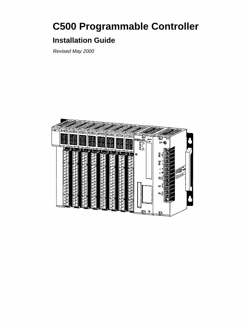
C500 Programmable ControllerInstallation GuideRevised May 2000

iv
!
!
!
v
Notice:OMRON products are manufactured for use according to proper procedures by a qualified operatorand only for the purposes described in this manual.
The following conventions are used to indicate and classify precautions in this manual. Always heedthe information provided with them. Failure to heed precautions can result in injury to people or dam-age to the product.
DANGER Indicates information that, if not heeded, is likely to result in loss of life or serious injury.
WARNING Indicates information that, if not heeded, could possibly result in loss of life or serious injury.
Caution Indicates information that, if not heeded, could result in relatively serious or minor injury, dam-age to the product, or faulty operation.
OMRON Product ReferencesAll OMRON products are capitalized in this manual. The word “Unit” is also capitalized when it refersto an OMRON product, regardless of whether or not it appears in the proper name of the product.
The abbreviation “Ch,” which appears in some displays and on some OMRON products, often means“word” and is abbreviated “Wd” in documentation in this sense.
The abbreviation “PC” means Programmable Controller and is not used as an abbreviation for any-thing else.
Visual AidsThe following headings appear in the left column of the manual to help you locate different types ofinformation.
Note Indicates information of particular interest for efficient and convenient operationof the product.
1, 2, 3... 1. Indicates lists of one sort or another, such as procedures, checklists, etc.
OMRON, 1990All rights reserved. No part of this publication may be reproduced, stored in a retrieval system, or transmitted, in anyform, or by any means, mechanical, electronic, photocopying, recording, or otherwise, without the prior written permis-sion of OMRON.
No patent liability is assumed with respect to the use of the information contained herein. Moreover, because OMRON isconstantly striving to improve its high-quality products, the information contained in this manual is subject to changewithout notice. Every precaution has been taken in the preparation of this manual. Nevertheless, OMRON assumes noresponsibility for errors or omissions. Neither is any liability assumed for damages resulting from the use of the informa-tion contained in this publication.

vi
TABLE OF CONTENTS
vii
PRECAUTIONS . . . . . . . . . . . . . . . . . . . . . . . . . . . . . . . . . 1 Intended Audience . . . . . . . . . . . . . . . . . . . . . . . . . . . . . . . . . . . . . . . . . . . . . . . . . . . . . . . . . . . 2 General Precautions . . . . . . . . . . . . . . . . . . . . . . . . . . . . . . . . . . . . . . . . . . . . . . . . . . . . . . . . . . 3 Safety Precautions . . . . . . . . . . . . . . . . . . . . . . . . . . . . . . . . . . . . . . . . . . . . . . . . . . . . . . . . . . . 4 Operating Environment Precautions . . . . . . . . . . . . . . . . . . . . . . . . . . . . . . . . . . . . . . . . . . . . . 5 Application Precautions . . . . . . . . . . . . . . . . . . . . . . . . . . . . . . . . . . . . . . . . . . . . . . . . . . . . . .
SECTION 1Introduction . . . . . . . . . . . . . . . . . . . . . . . . . . . . . . . . . . . .
1-1 What is a Control System? . . . . . . . . . . . . . . . . . . . . . . . . . . . . . . . . . . . . . . . . . . . . . . . . . 1-2 The Role of the PC . . . . . . . . . . . . . . . . . . . . . . . . . . . . . . . . . . . . . . . . . . . . . . . . . . . . . . . 1-3 How Does a PC Work? . . . . . . . . . . . . . . . . . . . . . . . . . . . . . . . . . . . . . . . . . . . . . . . . . . . .
SECTION 2Description of All Components . . . . . . . . . . . . . . . . . . . . .
2-1 CPU Rack . . . . . . . . . . . . . . . . . . . . . . . . . . . . . . . . . . . . . . . . . . . . . . . . . . . . . . . . . . . . . . 2-2 CPU Power Supply . . . . . . . . . . . . . . . . . . . . . . . . . . . . . . . . . . . . . . . . . . . . . . . . . . . . . . . 2-3 Expansion I/O Backplane . . . . . . . . . . . . . . . . . . . . . . . . . . . . . . . . . . . . . . . . . . . . . . . . . . 2-4 I/O Power Supply . . . . . . . . . . . . . . . . . . . . . . . . . . . . . . . . . . . . . . . . . . . . . . . . . . . . . . . . 2-5 I/O Control Unit . . . . . . . . . . . . . . . . . . . . . . . . . . . . . . . . . . . . . . . . . . . . . . . . . . . . . . . . . 2-6 I/O Interface Unit . . . . . . . . . . . . . . . . . . . . . . . . . . . . . . . . . . . . . . . . . . . . . . . . . . . . . . . . 2-7 I/O Units . . . . . . . . . . . . . . . . . . . . . . . . . . . . . . . . . . . . . . . . . . . . . . . . . . . . . . . . . . . . . . . 2-8 Memory Packs . . . . . . . . . . . . . . . . . . . . . . . . . . . . . . . . . . . . . . . . . . . . . . . . . . . . . . . . . .
SECTION 3Assembly . . . . . . . . . . . . . . . . . . . . . . . . . . . . . . . . . . . . . . .
3-1 Mounting the Units . . . . . . . . . . . . . . . . . . . . . . . . . . . . . . . . . . . . . . . . . . . . . . . . . . . . . . . 3-2 Memory Packs . . . . . . . . . . . . . . . . . . . . . . . . . . . . . . . . . . . . . . . . . . . . . . . . . . . . . . . . . . 3-3 System Configurations . . . . . . . . . . . . . . . . . . . . . . . . . . . . . . . . . . . . . . . . . . . . . . . . . . . .
SECTION 4System Connections . . . . . . . . . . . . . . . . . . . . . . . . . . . . . .
4-1 Current Consumption . . . . . . . . . . . . . . . . . . . . . . . . . . . . . . . . . . . . . . . . . . . . . . . . . . . . . 4-2 I/O Connections . . . . . . . . . . . . . . . . . . . . . . . . . . . . . . . . . . . . . . . . . . . . . . . . . . . . . . . . .
SECTION 5Installation Environment . . . . . . . . . . . . . . . . . . . . . . . . .
5-1 Cooling . . . . . . . . . . . . . . . . . . . . . . . . . . . . . . . . . . . . . . . . . . . . . . . . . . . . . . . . . . . . . . . . 5-2 Mounting Requirements . . . . . . . . . . . . . . . . . . . . . . . . . . . . . . . . . . . . . . . . . . . . . . . . . . . 5-3 Duct Work . . . . . . . . . . . . . . . . . . . . . . . . . . . . . . . . . . . . . . . . . . . . . . . . . . . . . . . . . . . . . 5-4 Preventing Noise . . . . . . . . . . . . . . . . . . . . . . . . . . . . . . . . . . . . . . . . . . . . . . . . . . . . . . . .
SECTION 6Power Considerations . . . . . . . . . . . . . . . . . . . . . . . . . . . . SECTION 7Safety Considerations . . . . . . . . . . . . . . . . . . . . . . . . . . . . Appendices
A Inspection and Maintenance . . . . . . . . . . . . . . . . . . . . . . . . . . . . . . . . . . . . . . . . . . . . . . . . . . B Specifications . . . . . . . . . . . . . . . . . . . . . . . . . . . . . . . . . . . . . . . . . . . . . . . . . . . . . . . . . . . . . . C Standard Models . . . . . . . . . . . . . . . . . . . . . . . . . . . . . . . . . . . . . . . . . . . . . . . . . . . . . . . . . . .
Glossary . . . . . . . . . . . . . . . . . . . . . . . . . . . . . . . . . . . . . . . Index . . . . . . . . . . . . . . . . . . . . . . . . . . . . . . . . . . . . . . . . . . Revision History . . . . . . . . . . . . . . . . . . . . . . . . . . . . . . . . .

ix
About this Manual:
This manual describes the installation of the C500 Programmable Controller and includes the sectionsdescribed below.
Please read this manual carefully and be sure you understand the information provided before attemptingto install and operate the C500 Programmable Controller. Be sure to read the following section beforeoperating the C500 Programmable Controller.
Section 1 is an introduction to Programmable Controllers. General information about what a Programma-ble Controller can do and how a Programmable Controller works is provided.
Section 2 provides a description of all the components of the C500. The names of all the individual partsof each Unit are given.
Section 3 explains how to assemble the C500. A detailed description of how to mount each Unit is pro-vided.
Section 4 outlines the system connections involved in installing a C500 Programmable Controller Sys-tems.
Section 5 contains the requirements for the installation environment of the C500. Suggestions for pre-venting electrical noise are included.
Section 6 explains the power considerations involved in installing the C500.
Section 7 lists safety considerations that should be kept in mind while installing the C500.
Appendixes , a Glossary , and an Index are also included.
WARNING Failure to read and understand the information provided in this manual may result inpersonal injury or death, damage to the product, or product failure. Please read eachsection in its entirety and be sure you understand the information provided in the sectionand related sections before attempting any of the procedures or operations given.
!

xi
PRECAUTIONS
This section provides general precautions for using the Programmable Controller (PC) and related devices.
The information contained in this section is important for the safe and reliable application of the PC. You must readthis section and understand the information contained before attempting to set up or operate a PC system.
1 Intended Audience . . . . . . . . . . . . . . . . . . . . . . . . . . . . . . . . . . . . . . . . . . . . . . . . . . . . . . . . . . . . 2 General Precautions . . . . . . . . . . . . . . . . . . . . . . . . . . . . . . . . . . . . . . . . . . . . . . . . . . . . . . . . . . . 3 Safety Precautions . . . . . . . . . . . . . . . . . . . . . . . . . . . . . . . . . . . . . . . . . . . . . . . . . . . . . . . . . . . . 4 Operating Environment Precautions . . . . . . . . . . . . . . . . . . . . . . . . . . . . . . . . . . . . . . . . . . . . . . 5 Application Precautions . . . . . . . . . . . . . . . . . . . . . . . . . . . . . . . . . . . . . . . . . . . . . . . . . . . . . . . .

!
!
!
!
3Safety Precautions
xii
1 Intended AudienceThis manual is intended for the following personnel, who must also have knowl-edge of electrical systems (an electrical engineer or the equivalent).
• Personnel in charge of installing FA systems.
• Personnel in charge of designing FA systems.
• Personnel in charge of managing FA systems and facilities.
2 General PrecautionsThe user must operate the product according to the performance specificationsdescribed in the operation manuals.
Before using the product under conditions which are not described in the manualor applying the product to nuclear control systems, railroad systems, aviationsystems, vehicles, combustion systems, medical equipment, amusementmachines, safety equipment, and other systems, machines, and equipment thatmay have a serious influence on lives and property if used improperly, consultyour OMRON representative.
Make sure that the ratings and performance characteristics of the product aresufficient for the systems, machines, and equipment, and be sure to provide thesystems, machines, and equipment with double safety mechanisms.
This manual provides information for programming and operating OMRON PCs.Be sure to read this manual before attempting to use the software and keep thismanual close at hand for reference during operation.
WARNING It is extremely important that a PC and all PC Units be used for the specifiedpurpose and under the specified conditions, especially in applications that candirectly or indirectly affect human life. You must consult with your OMRONrepresentative before applying a PC System to the abovementionedapplications.
3 Safety Precautions
WARNING Do not attempt to take any Unit apart while the power is being supplied. Doing somay result in electric shock.
WARNING Do not touch any of the terminals or terminal blocks while the power is beingsupplied. Doing so may result in electric shock.
WARNING Do not attempt to disassemble, repair, or modify any Units. Any attempt to do somay result in malfunction, fire, or electric shock.

!
!
!
!
!
5Application Precautions
xiii
4 Operating Environment Precautions
Caution Do not operate the control system in the following locations:
• Locations subject to direct sunlight.
• Locations subject to temperatures or humidity outside the range specified inthe specifications.
• Locations subject to condensation as the result of severe changes in tempera-ture.
• Locations subject to corrosive or flammable gases.
• Locations subject to dust (especially iron dust) or salts.
• Locations subject to exposure to water, oil, or chemicals.
• Locations subject to shock or vibration.
Caution Take appropriate and sufficient countermeasures when installing systems in thefollowing locations:
• Locations subject to static electricity or other forms of noise.
• Locations subject to strong electromagnetic fields.
• Locations subject to possible exposure to radioactivity.
• Locations close to power supplies.
Caution The operating environment of the PC system can have a large effect on the lon-gevity and reliability of the system. Improper operating environments can lead tomalfunction, failure, and other unforeseeable problems with the PC system. Besure that the operating environment is within the specified conditions at installa-tion and remains within the specified conditions during the life of the system.
5 Application PrecautionsObserve the following precautions when using the PC system.
WARNING Always heed these precautions. Failure to abide by the following precautionscould lead to serious or possibly fatal injury.
• Always ground the system to 100 Ω or less when installing the Units. Not con-necting to a ground of 100 Ω or less may result in electric shock.
• Always turn OFF the power supply to the PC before attempting any of the fol-lowing. Not turning OFF the power supply may result in malfunction or electricshock.
• Mounting or dismounting I/O Units, CPU Units, Memory Units, or any otherUnits.
• Assembling the Units.
• Setting DIP switches or rotary switches.
• Connecting cables or wiring the system.
• Connecting or disconnecting the connectors.
Caution Failure to abide by the following precautions could lead to faulty operation of thePC or the system, or could damage the PC or PC Units. Always heed these pre-cautions.
• Fail-safe measures must be taken by the customer to ensure safety in theevent of incorrect, missing, or abnormal signals caused by broken signal lines,momentary power interruptions, or other causes.

5Application Precautions
xiv
• Interlock circuits, limit circuits, and similar safety measures in external circuits(i.e., not in the Programmable Controller) must be provided by the customer.
• Always use the power supply voltages specified in this manual. An incorrectvoltage may result in malfunction or burning.
• Take appropriate measures to ensure that the specified power with the ratedvoltage and frequency is supplied. Be particularly careful in places where thepower supply is unstable. An incorrect power supply may result in malfunction.
• Install external breakers and take other safety measures against short-circuit-ing in external wiring. Insufficient safety measures against short-circuiting mayresult in burning.
• Do not apply voltages to the Input Units in excess of the rated input voltage.Excess voltages may result in burning.
• Do not apply voltages or connect loads to the Output Units in excess of themaximum switching capacity. Excess voltage or loads may result in burning.
• Disconnect the functional ground terminal when performing withstand voltagetests. Not disconnecting the functional ground terminal may result in burning.
• Be sure that all the mounting screws, terminal screws, and cable connectorscrews are tightened to the torque specified in this manual. Incorrect tighten-ing torque may result in malfunction.
• Leave the label attached to the Unit when wiring. Removing the label may re-sult in malfunction if foreign matter enters the Unit.
• Remove the label after the completion of wiring to ensure proper heat dissipa-tion. Leaving the label attached may result in malfunction.
• Double-check all wiring and switch settings before turning ON the power sup-ply. Incorrect wiring may result in burning.
• Wire correctly. Incorrect wiring may result in burning.
• Mount Units only after checking terminal blocks and connectors completely.
• Be sure that the terminal blocks, Memory Units, expansion cables, and otheritems with locking devices are properly locked into place. Improper lockingmay result in malfunction.
• Check the user program for proper execution before actually running it on theUnit. Not checking the program may result in an unexpected operation.
• Confirm that no adverse effect will occur in the system before attempting any ofthe following. Not doing so may result in an unexpected operation.
• Changing the operating mode of the PC.
• Force-setting/force-resetting any bit in memory.
• Changing the present value of any word or any set value in memory.
• Resume operation only after transferring to the new CPU Unit the contents ofthe DM Area, HR Area, and other data required for resuming operation. Notdoing so may result in an unexpected operation.
• Do not pull on the cables or bend the cables beyond their natural limit. Doingeither of these may break the cables.
• Do not place objects on top of the cables or other wiring lines. Doing so maybreak the cables.
• Use crimp terminals for wiring. Do not connect bare stranded wires directly toterminals. Connection of bare stranded wires may result in burning.
• When replacing parts, be sure to confirm that the rating of a new part is correct.Not doing so may result in malfunction or burning.
• Before touching a Unit, be sure to first touch a grounded metallic object in orderto discharge any static built-up. Not doing so may result in malfunction or dam-age.

1
SECTION 1Introduction
1-1 What is a Control System? . . . . . . . . . . . . . . . . . . . . . . . . . . . . . . . . . . . . . . . . . . . . . . . . . . 1-2 The Role of the PC . . . . . . . . . . . . . . . . . . . . . . . . . . . . . . . . . . . . . . . . . . . . . . . . . . . . . . . .
1-2-1 Input Devices . . . . . . . . . . . . . . . . . . . . . . . . . . . . . . . . . . . . . . . . . . . . . . . . . . . . . 1-2-2 Output Devices . . . . . . . . . . . . . . . . . . . . . . . . . . . . . . . . . . . . . . . . . . . . . . . . . . .
1-3 How Does a PC Work? . . . . . . . . . . . . . . . . . . . . . . . . . . . . . . . . . . . . . . . . . . . . . . . . . . . . .
Section 1Introduction
2
IntroductionThis section provides general information about Programmable Controllers(Systems) and how they fit into a Control System.
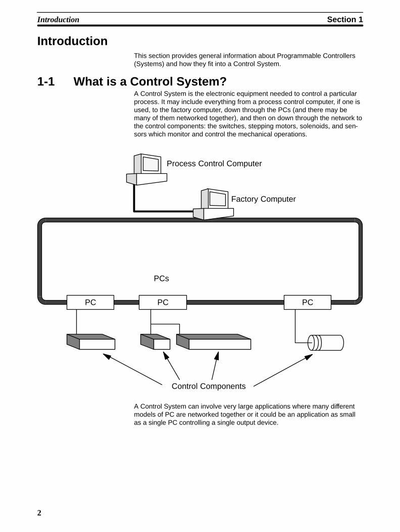
1-1 What is a Control System?A Control System is the electronic equipment needed to control a particularprocess. It may include everything from a process control computer, if one isused, to the factory computer, down through the PCs (and there may bemany of them networked together), and then on down through the network tothe control components: the switches, stepping motors, solenoids, and sen-sors which monitor and control the mechanical operations.
PC PC PC
PCs
Process Control Computer
Factory Computer
Control Components
A Control System can involve very large applications where many differentmodels of PC are networked together or it could be an application as smallas a single PC controlling a single output device.
Section 1Introduction
3
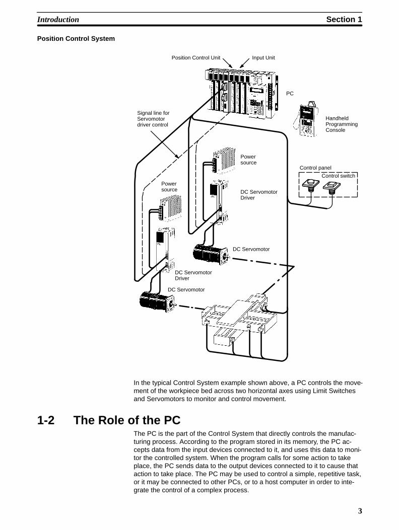
Position Control System
Control switch
Control panel
Signal line forServomotordriver control
Position Control Unit Input Unit
PC
HandheldProgrammingConsole
Powersource
DC ServomotorDriver
DC Servomotor
DC ServomotorDriver
DC Servomotor
Powersource
In the typical Control System example shown above, a PC controls the move-ment of the workpiece bed across two horizontal axes using Limit Switchesand Servomotors to monitor and control movement.
1-2 The Role of the PCThe PC is the part of the Control System that directly controls the manufac-turing process. According to the program stored in its memory, the PC ac-cepts data from the input devices connected to it, and uses this data to moni-tor the controlled system. When the program calls for some action to takeplace, the PC sends data to the output devices connected to it to cause thataction to take place. The PC may be used to control a simple, repetitive task,or it may be connected to other PCs, or to a host computer in order to inte-grate the control of a complex process.

Section 1Introduction
4
1-2-1 Input DevicesPCs can receive input from either automated or manual devices. The PCcould receive data from the user via a pushbutton switch, keyboard, or simi-lar device. Automated input could come from a variety of devices: micro-switches, timers, encoders, photosensors, and so on. Some devices, like theLimit Switch shown below, turn ON or OFF when the equipment actuallymakes contact with them. Other devices, like the Photoelectric Switch andProximity Switch shown below, use other means, such as light or inductance,in order to get information about the equipment being monitored.
Photoelectric Switch
Limit Switch
Proximity Switch
1-2-2 Output DevicesA PC can output to a myriad of devices for use in automated control. Almostanything that you can think of could be controlled (perhaps indirectly) by aPC. Some of the most common devices are motors, Solenoids, Servomotors,Stepping Motors, valves, switches, indicator lights, buzzers, and alarms.Some of these output devices, such as the motors, Solenoids, Servomotors,Stepping Motors, and valves, affect the controlled system directly. Others,such as the indicator lights, buzzers, and alarms, provide output to notify per-sonnel.
SolenoidServomotor
Stepping Motor
Section 1Introduction
5
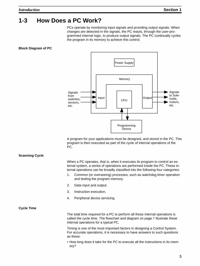
1-3 How Does a PC Work?PCs operate by monitoring input signals and providing output signals. Whenchanges are detected in the signals, the PC reacts, through the user-pro-grammed internal logic, to produce output signals. The PC continually cyclesthe program in its memory to achieve this control.
Block Diagram of PC
Power Supply
Input OutputCPU
Memory
ProgrammingDevice
Signalsfromswitches,sensors,etc.
Signalsto Sole-noids,motors,etc.
A program for your applications must be designed, and stored in the PC. Thisprogram is then executed as part of the cycle of internal operations of thePC.
Scanning Cycle
When a PC operates, that is, when it executes its program to control an ex-ternal system, a series of operations are performed inside the PC. These in-ternal operations can be broadly classified into the following four categories:
1. Common (or overseeing) processes, such as watchdog timer operationand testing the program memory.
2. Data input and output.
3. Instruction execution.
4. Peripheral device servicing.
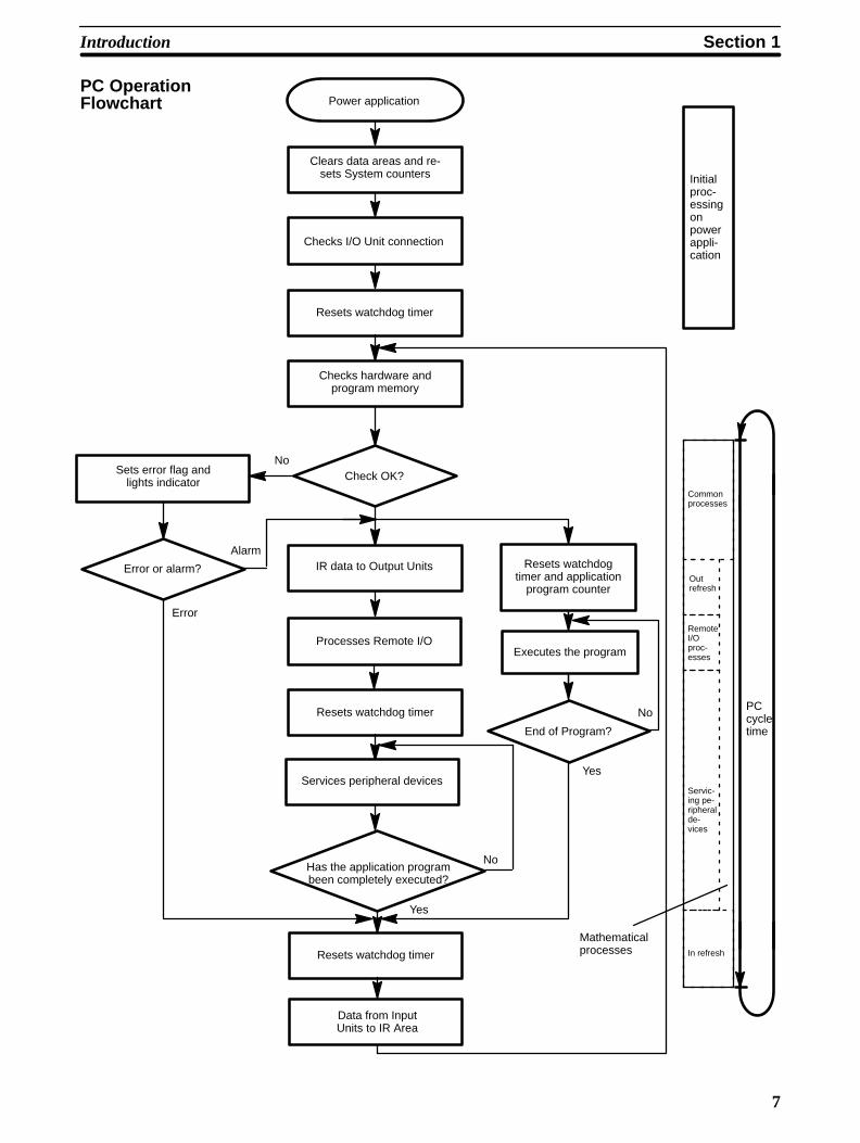
Cycle Time
The total time required for a PC to perform all these internal operations iscalled the cycle time. The flowchart and diagram on page 7 illustrate theseinternal operations for a typical PC.
Timing is one of the most important factors in designing a Control System.For accurate operations, it is necessary to have answers to such questionsas these:
• How long does it take for the PC to execute all the instructions in its mem-ory?

Section 1Introduction
6
• How long does it take for the PC to produce a control output in response toa given input signal?
The cycle time of the PC can be automatically calculated and monitored, butit is necessary to have an understanding of the timing relationships within thePC for effective System design and programming.
Section 1Introduction
7
Check OK?
IR data to Output Units
Power application
No
Yes
Checks I/O Unit connection
Resets watchdog timer
Clears data areas and re-sets System counters
Processes Remote I/O
Resets watchdog timer
Services peripheral devices
Checks hardware andprogram memory
Sets error flag andlights indicator
Error or alarm?
Error
Alarm
PCcycletime
Initialproc-essingonpowerappli-cation
PC OperationFlowchart
Has the application programbeen completely executed?
No
Yes
Resets watchdog timer
Data from InputUnits to IR Area
Commonprocesses
Outrefresh
Servic-ing pe-ripheralde-vices
In refresh
Resets watchdogtimer and application
program counter
Executes the program
End of Program?
No
RemoteI/Oproc-esses
Mathematicalprocesses
9
SECTION 2Description of All Components
2-1 CPU Rack . . . . . . . . . . . . . . . . . . . . . . . . . . . . . . . . . . . . . . . . . . . . . . . . . . . . . . . . . . . . . . . 2-2 CPU Power Supply . . . . . . . . . . . . . . . . . . . . . . . . . . . . . . . . . . . . . . . . . . . . . . . . . . . . . . . 2-3 Expansion I/O Backplane . . . . . . . . . . . . . . . . . . . . . . . . . . . . . . . . . . . . . . . . . . . . . . . . . . . 2-4 I/O Power Supply . . . . . . . . . . . . . . . . . . . . . . . . . . . . . . . . . . . . . . . . . . . . . . . . . . . . . . . . . 2-5 I/O Control Unit . . . . . . . . . . . . . . . . . . . . . . . . . . . . . . . . . . . . . . . . . . . . . . . . . . . . . . . . . . 2-6 I/O Interface Unit . . . . . . . . . . . . . . . . . . . . . . . . . . . . . . . . . . . . . . . . . . . . . . . . . . . . . . . . . 2-7 I/O Units . . . . . . . . . . . . . . . . . . . . . . . . . . . . . . . . . . . . . . . . . . . . . . . . . . . . . . . . . . . . . . . . 2-8 Memory Packs . . . . . . . . . . . . . . . . . . . . . . . . . . . . . . . . . . . . . . . . . . . . . . . . . . . . . . . . . . .
Section 2Description of All Components
10
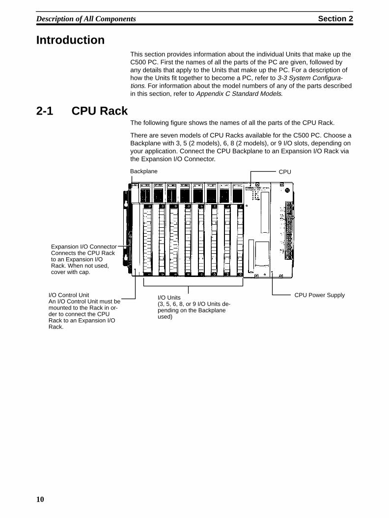
IntroductionThis section provides information about the individual Units that make up theC500 PC. First the names of all the parts of the PC are given, followed byany details that apply to the Units that make up the PC. For a description ofhow the Units fit together to become a PC, refer to 3-3 System Configura-tions. For information about the model numbers of any of the parts describedin this section, refer to Appendix C Standard Models.
2-1 CPU RackThe following figure shows the names of all the parts of the CPU Rack.
There are seven models of CPU Racks available for the C500 PC. Choose aBackplane with 3, 5 (2 models), 6, 8 (2 models), or 9 I/O slots, depending onyour application. Connect the CPU Backplane to an Expansion I/O Rack viathe Expansion I/O Connector.
Backplane
Expansion I/O ConnectorConnects the CPU Rackto an Expansion I/ORack. When not used,cover with cap.
I/O Control Unit An I/O Control Unit must bemounted to the Rack in or-der to connect the CPURack to an Expansion I/ORack.
I/O Units (3, 5, 6, 8, or 9 I/O Units de-pending on the Backplaneused)
CPU
CPU Power Supply
Section 2Description of All Components
11
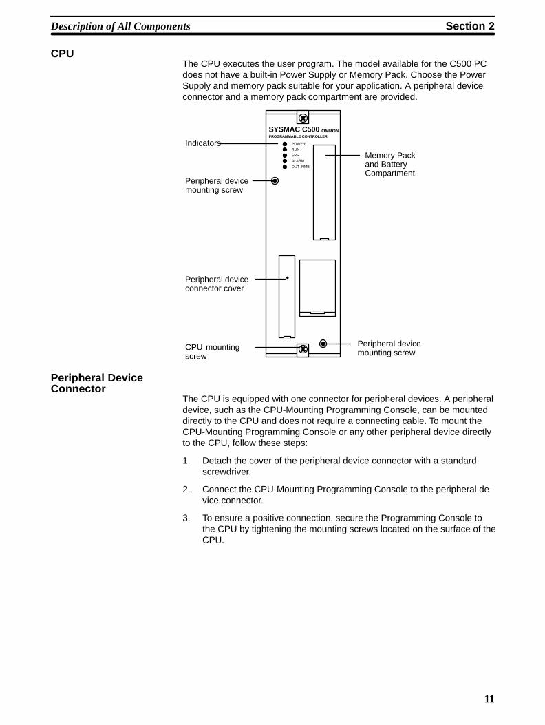
CPUThe CPU executes the user program. The model available for the C500 PCdoes not have a built-in Power Supply or Memory Pack. Choose the PowerSupply and memory pack suitable for your application. A peripheral deviceconnector and a memory pack compartment are provided.
SYSMAC C500PROGRAMMABLE CONTROLLER
POWER
RUN
ERR
ALARM
OUT INMB
•
Peripheral devicemounting screw
Peripheral deviceconnector cover
CPU mountingscrew
Memory Packand BatteryCompartment
OMRON
Peripheral devicemounting screw
Indicators
Peripheral DeviceConnector
The CPU is equipped with one connector for peripheral devices. A peripheraldevice, such as the CPU-Mounting Programming Console, can be mounteddirectly to the CPU and does not require a connecting cable. To mount theCPU-Mounting Programming Console or any other peripheral device directlyto the CPU, follow these steps:
1. Detach the cover of the peripheral device connector with a standardscrewdriver.
2. Connect the CPU-Mounting Programming Console to the peripheral de-vice connector.
3. To ensure a positive connection, secure the Programming Console tothe CPU by tightening the mounting screws located on the surface of theCPU.

Section 2Description of All Components
12
2-2 CPU Power SupplyThe CPU Power Supply is mounted to the rightmost slot of the CPU Rack.Three models of Power Supplies are available: 100 to 120 VAC, 200 to 240VAC, and 24 VDC. The following table summarizes the output capacity of thethree models and the current available for I/O Units mounted on the CPURack.
Model Supply Voltage OutputCapacity
Available Currentfor I/O Units
24 VDC OutputTerminal
3G2A5-PS221-E 100 to 120/200 to 240 VAC
7 A 5 VDC 5 A Provided
3G2A5-PS223-E200 to 240 VAC(selectable) 12 A 5 VDC 10 A Not provided
3G2A5-PS213-E 24 VDC 9 A 5 VDC 5 A Not provided
Note Be sure to keep the total power consumed by all the Units mountedon a Rack within the value stated in the table above. For example, donot mount I/O Units with a total current consumption of 6 A to a Racksupplied by a 7 A Power Supply. As shown in the table above, theavailable current for I/O Units is only 5 A. For details concerning cur-rent consumption, refer to Section 4 System Connections.
3G2A5-PS221-E
–
++
•
Mounting screwDo not loosen this screw.
Fuse holderContains a MF61NR fuse(3 A, 250 V, 6.35-dia. x32)
POWER indicatorLights when power is supplied.
Terminals forexternal connections
Mounting screwDo not loosen this screw.
AC input
Voltage selectorShort: 100 to 120 VOpen: 200 to 240 V
LG
GR
0.8 A, 24 VDC output
START input
RUN output
Connect a 100 to 120 VAC or 200 to240 VAC power source.
Short these terminals to select 100 to120 VAC. Open them to select 200 to240 VAC.
Ground this terminal at a resistance ofless than 100 Ω to improve noise im-munity or prevent electric shock.
Ground this terminal at a resistanceof less than 100 Ω to prevent electricshock.Use these terminals to supply powerto DC Input Units. Use a separatePower Supply if the I/O Unit requiresmore than 0.8 A. If a current higherthan 0.8 A is output, the PC stops.
These terminals are short-circuited asa factory-set condition. Remove theshort-circuit bracket to start or stopthe PC with an external signal. Nor-mally, leave them short-circuited.
These terminals are turned ON dur-ing RUN operation.
Section 2Description of All Components
13
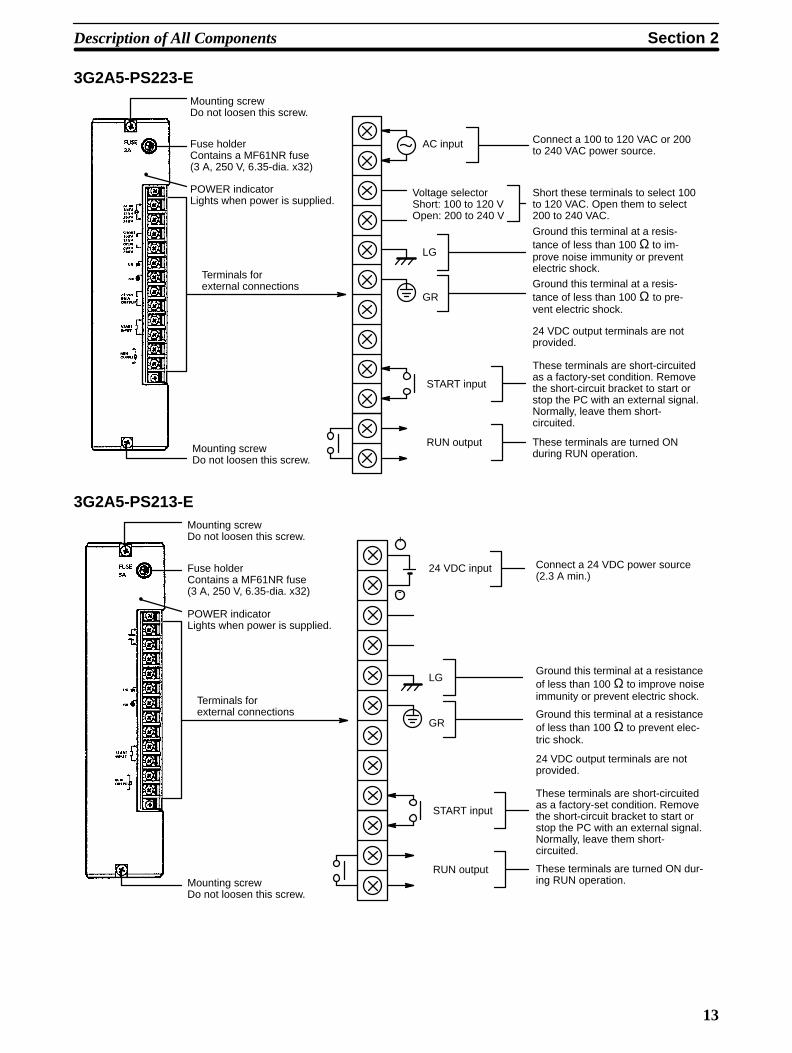
3G2A5-PS223-E
•
Mounting screwDo not loosen this screw.
Fuse holderContains a MF61NR fuse(3 A, 250 V, 6.35-dia. x32)
POWER indicatorLights when power is supplied.
Terminals forexternal connections
Mounting screwDo not loosen this screw.
AC input
Voltage selectorShort: 100 to 120 VOpen: 200 to 240 V
LG
GR
START input
RUN output
Connect a 100 to 120 VAC or 200to 240 VAC power source.
Short these terminals to select 100to 120 VAC. Open them to select200 to 240 VAC.
Ground this terminal at a resis-tance of less than 100 Ω to im-prove noise immunity or preventelectric shock.
Ground this terminal at a resis-tance of less than 100 Ω to pre-vent electric shock.
24 VDC output terminals are notprovided.
These terminals are short-circuitedas a factory-set condition. Removethe short-circuit bracket to start orstop the PC with an external signal.Normally, leave them short-circuited.
These terminals are turned ONduring RUN operation.
3G2A5-PS213-E
-
+
•
Mounting screwDo not loosen this screw.
Fuse holderContains a MF61NR fuse(3 A, 250 V, 6.35-dia. x32)
POWER indicatorLights when power is supplied.
Terminals forexternal connections
Mounting screwDo not loosen this screw.
24 VDC input
LG
GR
START input
RUN output
Connect a 24 VDC power source(2.3 A min.)
Ground this terminal at a resistanceof less than 100 Ω to improve noiseimmunity or prevent electric shock.
Ground this terminal at a resistanceof less than 100 Ω to prevent elec-tric shock.
24 VDC output terminals are notprovided.
These terminals are short-circuitedas a factory-set condition. Removethe short-circuit bracket to start orstop the PC with an external signal.Normally, leave them short-circuited.
These terminals are turned ON dur-ing RUN operation.
Section 2Description of All Components
14
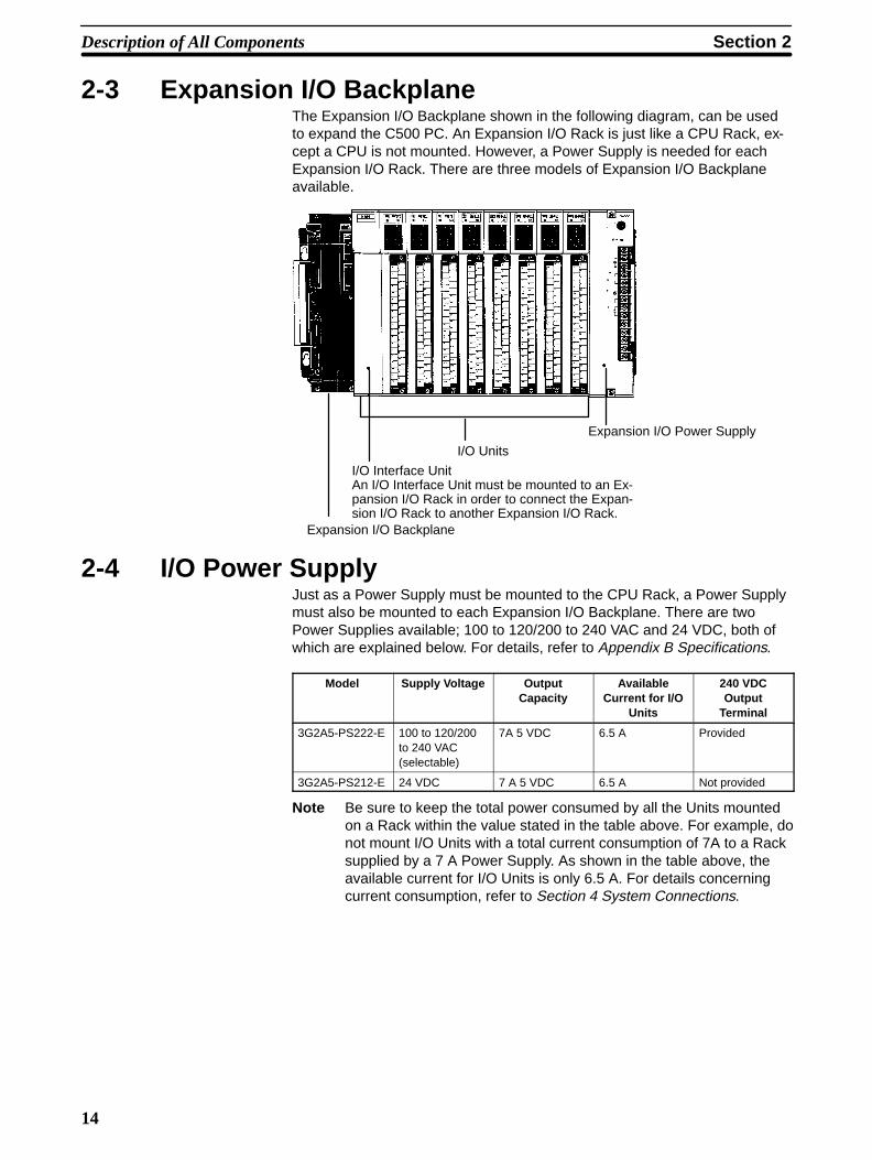
2-3 Expansion I/O BackplaneThe Expansion I/O Backplane shown in the following diagram, can be usedto expand the C500 PC. An Expansion I/O Rack is just like a CPU Rack, ex-cept a CPU is not mounted. However, a Power Supply is needed for eachExpansion I/O Rack. There are three models of Expansion I/O Backplaneavailable.
Expansion I/O Backplane
I/O Interface UnitAn I/O Interface Unit must be mounted to an Ex-pansion I/O Rack in order to connect the Expan-sion I/O Rack to another Expansion I/O Rack.
I/O Units
Expansion I/O Power Supply
2-4 I/O Power SupplyJust as a Power Supply must be mounted to the CPU Rack, a Power Supplymust also be mounted to each Expansion I/O Backplane. There are twoPower Supplies available; 100 to 120/200 to 240 VAC and 24 VDC, both ofwhich are explained below. For details, refer to Appendix B Specifications.
Model Supply Voltage OutputCapacity
AvailableCurrent for I/O
Units
240 VDCOutput
Terminal
3G2A5-PS222-E 100 to 120/200to 240 VAC(selectable)
7A 5 VDC 6.5 A Provided
3G2A5-PS212-E 24 VDC 7 A 5 VDC 6.5 A Not provided
Note Be sure to keep the total power consumed by all the Units mountedon a Rack within the value stated in the table above. For example, donot mount I/O Units with a total current consumption of 7A to a Racksupplied by a 7 A Power Supply. As shown in the table above, theavailable current for I/O Units is only 6.5 A. For details concerningcurrent consumption, refer to Section 4 System Connections.

Section 2Description of All Components
15
3G2A5-PS222-E
Connect a 100 to 120 VAC or 200 to240 VAC power source
Short these terminals to select 100 to120 VAC. Open them to select 200 to240 VAC.
Ground this terminal at a resistanceof less than 100 Ω to improve noiseimmunity or prevent electric shock.
Ground this terminal at a resistanceof less than 100 Ω to prevent electricshock.
Use these terminals to supply powerto DC Input Units. Use a separatePower Supply if the I/O Unit operateon more than 0.8 A. If a current higherthan 0.8 A is output, the PC stops.
These terminals are used to supplyexternal DC Input Units. If the Unit re-quires more than 0.8 A a separatesupply must be used. The PC shuts offautomatically if a current of more than0.8 A is drawn from the supply.
•
Mounting screwDo not loosen this screw.
Fuse holderContains a MF61NR fuse(3 A, 250 V, 6.35-dia. x32)
POWER indicatorLights when power is supplied.
Terminals forexternal connections
Mounting screwDo not loosen this screw.
AC input
Voltage selectorShort: 100 to 120 VOpen: 200 to 240 V
LG
GR+
-0.8 A, 24 VDC output
3G2A5-PS212-E
•
Mounting screwDo not loosen this screw.
Fuse holderContains a MF61NR fuse(3 A, 250 V, 6.35-dia. x32)
POWER indicatorLights when power is supplied.
Terminals forexternal connections
Mounting screwDo not loosen this screw.
LG
GR
+
-
24 VDC input Connect a 24-VDC power source (2.3A min.)
Ground this terminal at a resistanceof less than 100 Ω to improve noiseimmunity or prevent electric shock.
Ground this terminal at a resistanceof less than 100 Ω to prevent electricshock.
Section 2Description of All Components
16
2-5 I/O Control UnitAn I/O Control Unit must be mounted to the CPU Rack in order to connectthe CPU Rack to an Expansion I/O Rack. An I/O Control Unit can bemounted even if no Expansion I/O Rack is used.
2-6 I/O Interface UnitAn I/O Interface Unit is needed on each Expansion I/O Rack, in order to ex-pand the PC. If there is not an I/O Interface Unit on each Expansion I/ORack, data communication cannot take place. The I/O Interface Unit ismounted to the leftmost I/O position on the Expansion I/O Backplane.
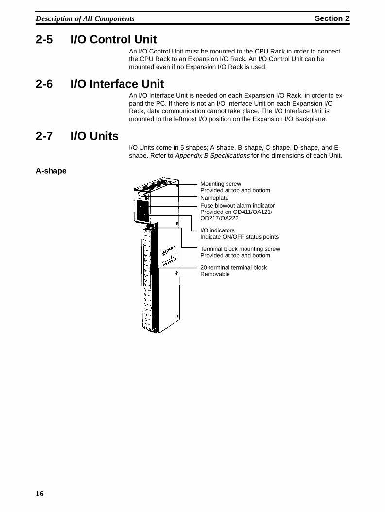
2-7 I/O UnitsI/O Units come in 5 shapes; A-shape, B-shape, C-shape, D-shape, and E-shape. Refer to Appendix B Specifications for the dimensions of each Unit.
A-shape
Mounting screwProvided at top and bottomNameplateFuse blowout alarm indicatorProvided on OD411/OA121/OD217/OA222
I/O indicatorsIndicate ON/OFF status points
Terminal block mounting screwProvided at top and bottom
20-terminal terminal blockRemovable
Section 2Description of All Components
17
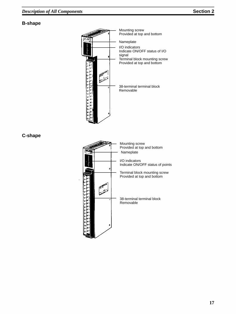
B-shapeMounting screwProvided at top and bottom
Nameplate
I/O indicatorsIndicate ON/OFF status of I/OsignalTerminal block mounting screwProvided at top and bottom
38-terminal terminal blockRemovable
C-shape
Mounting screwProvided at top and bottomNameplate
I/O indicatorsIndicate ON/OFF status of points
Terminal block mounting screwProvided at top and bottom
38-terminal terminal blockRemovable
Section 2Description of All Components
18
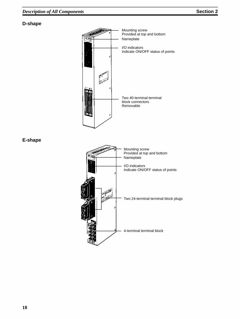
D-shapeMounting screwProvided at top and bottomNameplate
I/O indicatorsIndicate ON/OFF status of points
Two 40-terminal terminalblock connectorsRemovable
E-shape
Mounting screwProvided at top and bottomNameplate
I/O indicatorsIndicate ON/OFF status of points
Two 24-terminal terminal block plugs
4-terminal terminal block

!
Section 2Description of All Components
19
2-8 Memory PacksThe Memory Pack fits into the slot located on the left side of the CPU. Be-cause the Memory Pack is not provided with the PC upon delivery, a MemoryPack must be selected and installed in the CPU. There are two MemoryPacks available, either RAM or ROM, that can be used in the C500H PC.
RAM PackData can be randomly written to and read from the RAM Pack, making it pos-sible to enter your own program into the CPU. However, because this is not afixed program, the memory of the RAM Pack is erased when power is notsupplied to the CPU or when the RAM Pack is removed from the CPU.
Caution Do not remove the battery in the CPU when the RAM Pack has been removedfrom the CPU.
RAM Pack
CHIP 0 CHIP 1 CHIP 264 128
Two models of RAM Packs are available, which vary in memory capacity:16K, and 24K words. Refer to Appendix C Standard Models for model num-bers.
Using a Programming Console, execute FUN (01) and a search operation tocheck the amount of memory available.
Section 2Description of All Components
20
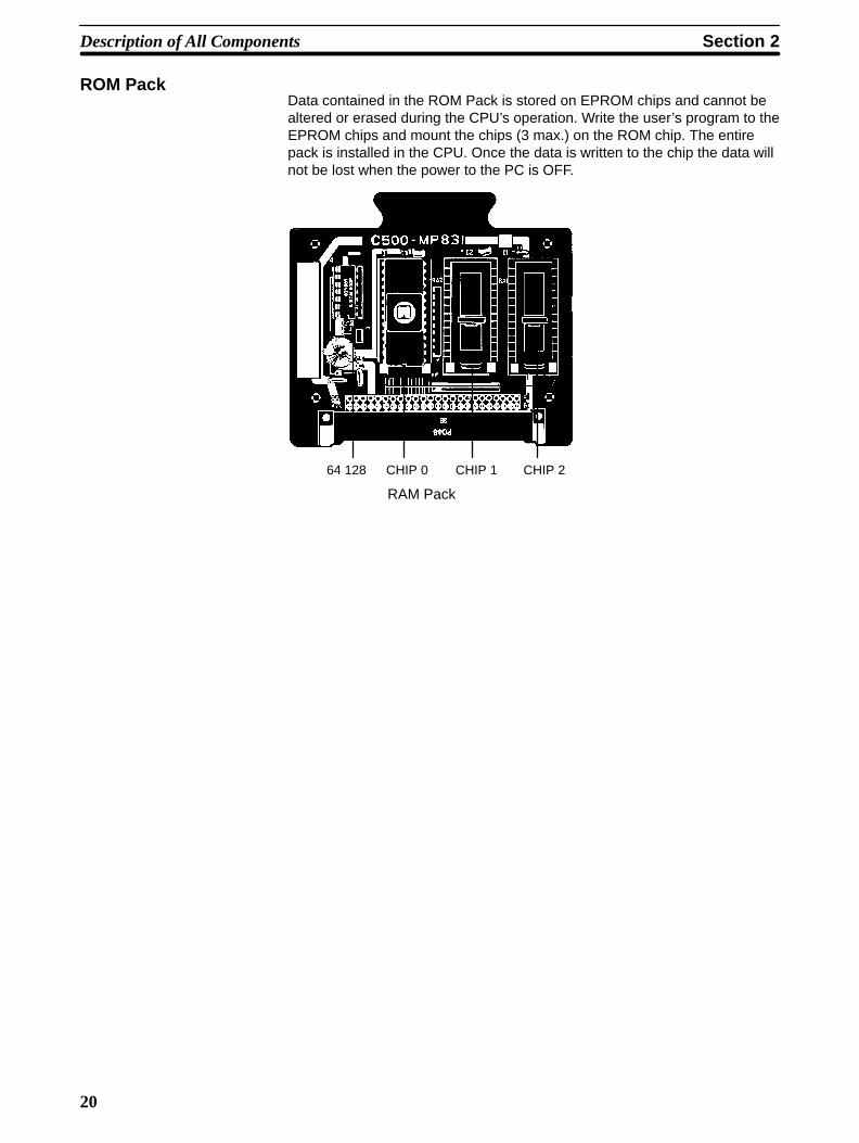
ROM PackData contained in the ROM Pack is stored on EPROM chips and cannot bealtered or erased during the CPU’s operation. Write the user’s program to theEPROM chips and mount the chips (3 max.) on the ROM chip. The entirepack is installed in the CPU. Once the data is written to the chip the data willnot be lost when the power to the PC is OFF.
RAM Pack
CHIP 0 CHIP 1 CHIP 264 128

21
SECTION 3Assembly
3-1 Mounting the Units . . . . . . . . . . . . . . . . . . . . . . . . . . . . . . . . . . . . . . . . . . . . . . . . . . . . . . . . 3-2 Memory Packs . . . . . . . . . . . . . . . . . . . . . . . . . . . . . . . . . . . . . . . . . . . . . . . . . . . . . . . . . . . 3-3 System Configurations . . . . . . . . . . . . . . . . . . . . . . . . . . . . . . . . . . . . . . . . . . . . . . . . . . . . .
Section 3Assembly
22
IntroductionWhen we speak of a PC, we usually think of it as a single object. But actuallyeven the simplest PCs are usually composed of several different devices. Infact a single PC can be physically spread throughout a building, but we stillcall it one PC.
In this section, we will start with a Backplane and use all the Units discussedin Section 2 Description of All Components to build a PC.
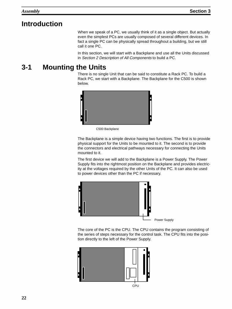
3-1 Mounting the UnitsThere is no single Unit that can be said to constitute a Rack PC. To build aRack PC, we start with a Backplane. The Backplane for the C500 is shownbelow.
C500 Backplane
The Backplane is a simple device having two functions. The first is to providephysical support for the Units to be mounted to it. The second is to providethe connectors and electrical pathways necessary for connecting the Unitsmounted to it.
The first device we will add to the Backplane is a Power Supply. The PowerSupply fits into the rightmost position on the Backplane and provides electric-ity at the voltages required by the other Units of the PC. It can also be usedto power devices other than the PC if necessary.
Power Supply
The core of the PC is the CPU. The CPU contains the program consisting ofthe series of steps necessary for the control task. The CPU fits into the posi-tion directly to the left of the Power Supply.
CPU
Section 3Assembly
23
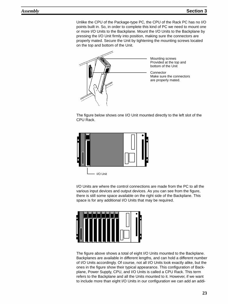
Unlike the CPU of the Package-type PC, the CPU of the Rack PC has no I/Opoints built in. So, in order to complete this kind of PC we need to mount oneor more I/O Units to the Backplane. Mount the I/O Units to the Backplane bypressing the I/O Unit firmly into position, making sure the connectors areproperly mated. Secure the Unit by tightening the mounting screws locatedon the top and bottom of the Unit.
Mounting screwsProvided at the top andbottom of the Unit
ConnectorMake sure the connectorsare properly mated.
The figure below shows one I/O Unit mounted directly to the left slot of theCPU Rack.
I/O Unit
I/O Units are where the control connections are made from the PC to all thevarious input devices and output devices. As you can see from the figure,there is still some space available on the right side of the Backplane. Thisspace is for any additional I/O Units that may be required.
The figure above shows a total of eight I/O Units mounted to the Backplane.Backplanes are available in different lengths, and can hold a different numberof I/O Units accordingly. Of course, not all I/O Units look exactly alike, but theones in the figure show their typical appearance. This configuration of Back-plane, Power Supply, CPU, and I/O Units is called a CPU Rack. This termrefers to the Backplane and all the Units mounted to it. However, if we wantto include more than eight I/O Units in our configuration we can add an addi-
Section 3Assembly
24
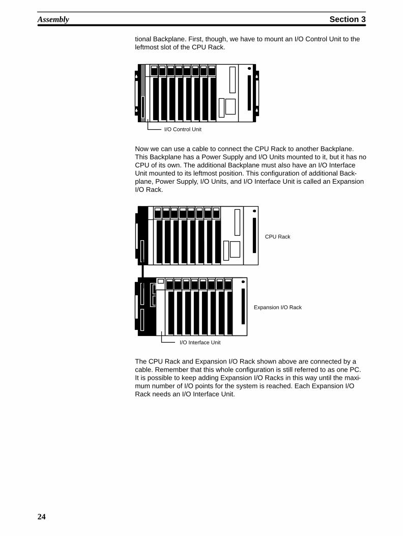
tional Backplane. First, though, we have to mount an I/O Control Unit to theleftmost slot of the CPU Rack.
I/O Control Unit
Now we can use a cable to connect the CPU Rack to another Backplane.This Backplane has a Power Supply and I/O Units mounted to it, but it has noCPU of its own. The additional Backplane must also have an I/O InterfaceUnit mounted to its leftmost position. This configuration of additional Back-plane, Power Supply, I/O Units, and I/O Interface Unit is called an ExpansionI/O Rack.
I/O Interface Unit
CPU Rack
Expansion I/O Rack
The CPU Rack and Expansion I/O Rack shown above are connected by acable. Remember that this whole configuration is still referred to as one PC.It is possible to keep adding Expansion I/O Racks in this way until the maxi-mum number of I/O points for the system is reached. Each Expansion I/ORack needs an I/O Interface Unit.
!
Section 3Assembly
25
3-2 Memory PacksThe CPU has a removable Memory Pack that stores the user program. TwoMemory Packs are available, in either RAM or ROM. You can write your ownprogram into the RAM Pack or you can copy a program that has alreadybeen written to an EPROM chip and mount it in the ROM Pack. The EPROMChip must be mounted to the PROM Writer in order for the program to bewritten to it. Then the EPROM Chip must be mounted to the ROM Pack.
Mounting the EPROMChip to the ROM Pack
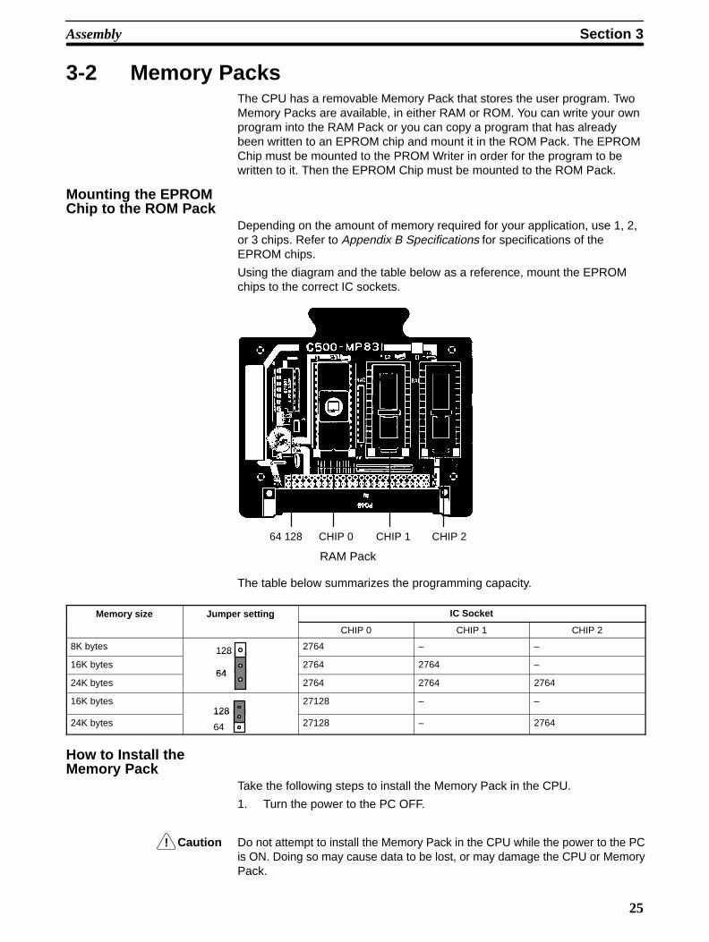
Depending on the amount of memory required for your application, use 1, 2,or 3 chips. Refer to Appendix B Specifications for specifications of theEPROM chips.
Using the diagram and the table below as a reference, mount the EPROMchips to the correct IC sockets.
RAM Pack
CHIP 0 CHIP 1 CHIP 264 128
The table below summarizes the programming capacity.
Memory size Jumper setting IC Sockety p g
CHIP 0 CHIP 1 CHIP 2
8K bytes 128 2764 – –
16K bytes64
128
2764 2764 –
24K bytes64
2764 2764 2764
16K bytes128
27128 – –
24K bytes 64
12827128 – 2764
How to Install theMemory Pack
Take the following steps to install the Memory Pack in the CPU.
1. Turn the power to the PC OFF.
Caution Do not attempt to install the Memory Pack in the CPU while the power to the PCis ON. Doing so may cause data to be lost, or may damage the CPU or MemoryPack.

Section 3Assembly
26
2. Using a standard screwdriver, remove the Memory Pack compartmentcover located on the front panel of the CPU. Push in the latch on thecover and slide the cover upward.
Use a standard screwdriver to remove the MemoryPack compartment cover.
SYSMAC C500PROGRAMMABLE CONTROLLER
POWER
RUN
ERR
ALARM
OUT INMB
•
OMRON
3. Insert the Memory Pack (component side facing left) into the Memorycompartment. When the Unit is almost completely inserted into the CPU,there may be a slight resistance as the Memory Pack connector mateswith the connector inside the CPU. Continue pushing on the MemoryPack until it is inserted completely into the CPU.
Memory Pack(ROM or RAM Pack)
Memory Unit guide
4. Reattach the memory compartment cover.
How to Remove theMemory Pack
Follow the steps below to remove the Memory Pack from the CPU.
1. Turn the power to the PC OFF.
2. Using a standard screwdriver, remove the Memory Pack compartmentcover located on the front panel of the CPU. Push in the latch on thecover and slide the cover upward.
3. Pull the Memory Pack up and out.
Section 3Assembly
27
Note Memory in the RAM Pack is erased when the Memory Pack isremoved from the CPU and when the CPU Unit is removed fromthe Rack.
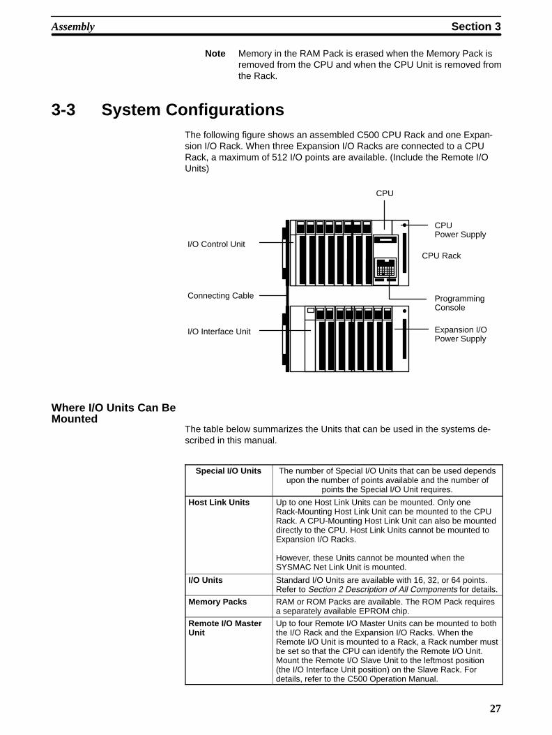
3-3 System ConfigurationsThe following figure shows an assembled C500 CPU Rack and one Expan-sion I/O Rack. When three Expansion I/O Racks are connected to a CPURack, a maximum of 512 I/O points are available. (Include the Remote I/OUnits)
I/O Control Unit
I/O Interface Unit
CPU
CPU Power Supply
CPU Rack
ProgrammingConsole
Expansion I/OPower Supply
Connecting Cable
Where I/O Units Can BeMounted
The table below summarizes the Units that can be used in the systems de-scribed in this manual.
Special I/O Units The number of Special I/O Units that can be used dependsupon the number of points available and the number of
points the Special I/O Unit requires.
Host Link Units Up to one Host Link Units can be mounted. Only oneRack-Mounting Host Link Unit can be mounted to the CPURack. A CPU-Mounting Host Link Unit can also be mounteddirectly to the CPU. Host Link Units cannot be mounted toExpansion I/O Racks.
However, these Units cannot be mounted when theSYSMAC Net Link Unit is mounted.
I/O Units Standard I/O Units are available with 16, 32, or 64 points.Refer to Section 2 Description of All Components for details.
Memory Packs RAM or ROM Packs are available. The ROM Pack requiresa separately available EPROM chip.
Remote I/O MasterUnit
Up to four Remote I/O Master Units can be mounted to boththe I/O Rack and the Expansion I/O Racks. When theRemote I/O Unit is mounted to a Rack, a Rack number mustbe set so that the CPU can identify the Remote I/O Unit.Mount the Remote I/O Slave Unit to the leftmost position(the I/O Interface Unit position) on the Slave Rack. Fordetails, refer to the C500 Operation Manual.

Section 3Assembly
28
The following table summarizes specific Units that can and cannot bemounted in the CPU and Expansion Racks and the number that can be usedin each PC. For more information about the Units, refer to the C500 Opera-tion Manual.
Unit CPU Rack Expansion Rack
16-, 32-, 64-point I/O YES YES
Special I/O YES YES
I/O Link YES YES
PC Link YES (2 max.) NO
Host Link YES (2 max.)* NO
SYSMAC Net Link YES (1 max.) NO
Remote I/O Master YES YES
Remote I/O Slave NO YES
*One Rack-mounting Host Link Unit can be mounted to the CPU Rack and one CPU-mounting Host Link Unit can be mounted directly tothe CPU Unit.
Notes 1. The Position Control Unit and the PID Unit each require two I/O slots on the CPU Rack and the Expansion I/O Racks
2. The following Units can only be mounted to one of the three orfive rightmost slots on the CPU Backplane, depending on whichBackplane is used. PC LinkHost LinkSYSMAC Net Link
3. When two or more PCs are linked by the PC Link Unit, a maxi-mum of 32 PC Link Units can be used (linking 31 PCs), in anynumber of subsystems.
4. SYSMAC Net Link and Host Link cannot be mounted simultane-ously.

29
SECTION 4System Connections
4-1 Current Consumption . . . . . . . . . . . . . . . . . . . . . . . . . . . . . . . . . . . . . . . . . . . . . . . . . . . . . . 4-2 I/O Connections . . . . . . . . . . . . . . . . . . . . . . . . . . . . . . . . . . . . . . . . . . . . . . . . . . . . . . . . . .
Section 4System Connections
30
IntroductionIn the preceding sections we have covered all the parts of a PC and how theyshould be assembled. This section provides detailed information on PC connec-tions.
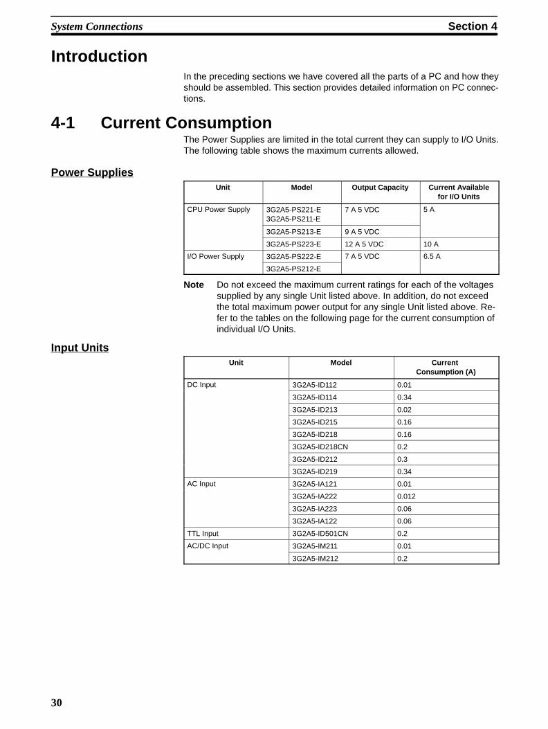
4-1 Current ConsumptionThe Power Supplies are limited in the total current they can supply to I/O Units.The following table shows the maximum currents allowed.
Power SuppliesUnit Model Output Capacity Current Available
for I/O Units
CPU Power Supply 3G2A5-PS221-E3G2A5-PS211-E
7 A 5 VDC 5 A
3G2A5-PS213-E 9 A 5 VDC
3G2A5-PS223-E 12 A 5 VDC 10 A
I/O Power Supply 3G2A5-PS222-E 7 A 5 VDC 6.5 Ay
3G2A5-PS212-E
Note Do not exceed the maximum current ratings for each of the voltagessupplied by any single Unit listed above. In addition, do not exceedthe total maximum power output for any single Unit listed above. Re-fer to the tables on the following page for the current consumption ofindividual I/O Units.
Input UnitsUnit Model Current
Consumption (A)
DC Input 3G2A5-ID112 0.01
3G2A5-ID114 0.34
3G2A5-ID213 0.02
3G2A5-ID215 0.16
3G2A5-ID218 0.16
3G2A5-ID218CN 0.2
3G2A5-ID212 0.3
3G2A5-ID219 0.34
AC Input 3G2A5-IA121 0.01
3G2A5-IA222 0.012
3G2A5-IA223 0.06
3G2A5-IA122 0.06
TTL Input 3G2A5-ID501CN 0.2
AC/DC Input 3G2A5-IM211 0.01
3G2A5-IM212 0.2
Section 4System Connections
31
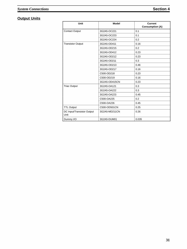
Output UnitsUnit Model Current
Consumption (A)
Contact Output 3G2A5-OC221 0.1
3G2A5-OC223 0.1
3G2A5-OC224 0.2
Transistor Output 3G2A5-OD411 0.16
3G2A5-OD215 0.2
3G2A5-OD412 0.23
3G2A5-OD212 0.23
3G2A5-OD211 0.3
3G2A5-OD213 0.46
3G2A5-OD217 0.16
C500-OD218 0.23
C500-OD219 0.16
3G2A5-OD415CN 0.23
Triac Output 3G2A5-OA121 0.3
3G2A5-OA222 0.3
3G2A5-OA223 0.45
C500-OA225 0.2
C500-OA226 0.45
TTL Output C500-OD501CN 0.25
DC Input/Transistor OutputUnit
3G2A5-MD211CN 0.26
Dummy I/O 3G2A5-DUM01 0.035
Section 4System Connections
32
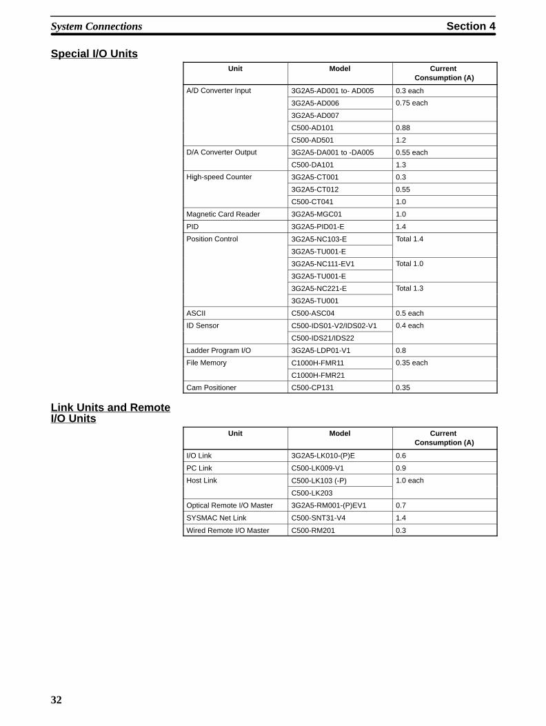
Special I/O UnitsUnit Model Current
Consumption (A)
A/D Converter Input 3G2A5-AD001 to- AD005 0.3 each
3G2A5-AD006 0.75 each
3G2A5-AD007
C500-AD101 0.88
C500-AD501 1.2
D/A Converter Output 3G2A5-DA001 to -DA005 0.55 each
C500-DA101 1.3
High-speed Counter 3G2A5-CT001 0.3g
3G2A5-CT012 0.55
C500-CT041 1.0
Magnetic Card Reader 3G2A5-MGC01 1.0
PID 3G2A5-PID01-E 1.4
Position Control 3G2A5-NC103-E Total 1.4
3G2A5-TU001-E
3G2A5-NC111-EV1 Total 1.0
3G2A5-TU001-E
3G2A5-NC221-E Total 1.3
3G2A5-TU001
ASCII C500-ASC04 0.5 each
ID Sensor C500-IDS01-V2/IDS02-V1 0.4 each
C500-IDS21/IDS22
Ladder Program I/O 3G2A5-LDP01-V1 0.8
File Memory C1000H-FMR11 0.35 eachy
C1000H-FMR21
Cam Positioner C500-CP131 0.35
Link Units and RemoteI/O Units
Unit Model Current Consumption (A)
I/O Link 3G2A5-LK010-(P)E 0.6
PC Link C500-LK009-V1 0.9
Host Link C500-LK103 (-P) 1.0 each
C500-LK203
Optical Remote I/O Master 3G2A5-RM001-(P)EV1 0.7
SYSMAC Net Link C500-SNT31-V4 1.4
Wired Remote I/O Master C500-RM201 0.3
Section 4System Connections
33
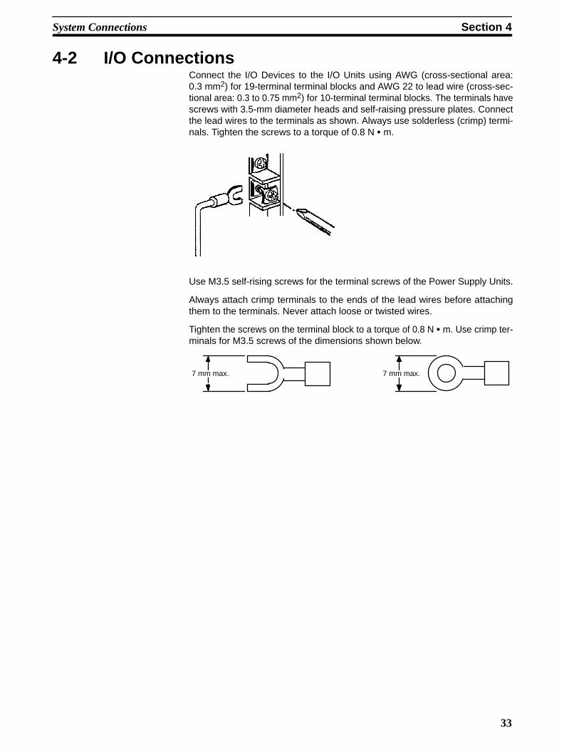
4-2 I/O ConnectionsConnect the I/O Devices to the I/O Units using AWG (cross-sectional area:0.3 mm2) for 19-terminal terminal blocks and AWG 22 to lead wire (cross-sec-tional area: 0.3 to 0.75 mm2) for 10-terminal terminal blocks. The terminals havescrews with 3.5-mm diameter heads and self-raising pressure plates. Connectthe lead wires to the terminals as shown. Always use solderless (crimp) termi-nals. Tighten the screws to a torque of 0.8 N m.
Use M3.5 self-rising screws for the terminal screws of the Power Supply Units.
Always attach crimp terminals to the ends of the lead wires before attachingthem to the terminals. Never attach loose or twisted wires.
Tighten the screws on the terminal block to a torque of 0.8 N m. Use crimp ter-minals for M3.5 screws of the dimensions shown below.
7 mm max.7 mm max.
Section 4System Connections
34
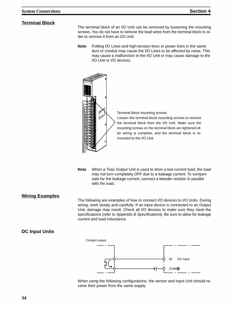
Terminal BlockThe terminal block of an I/O Unit can be removed by loosening the mountingscrews. You do not have to remove the lead wires from the terminal block in or-der to remove it from an I/O Unit.
Note Putting I/O Lines and high-tension lines or power lines in the sameduct or conduit may cause the I/O Lines to be affected by noise. Thismay cause a malfunction in the I/O Unit or may cause damage to theI/O Unit or I/O devices.
Terminal block mounting screwsLoosen the terminal block mounting screws to remove
the terminal block from the I/O Unit. Make sure themounting screws on the terminal block are tightened af-
ter wiring is complete, and the terminal block is re-mounted to the I/O Unit.
Note When a Triac Output Unit is used to drive a low-current load, the loadmay not turn completely OFF due to a leakage current. To compen-sate for the leakage current, connect a bleeder resistor in parallelwith the load.
Wiring ExamplesThe following are examples of how to connect I/O devices to I/O Units. Duringwiring, work slowly and carefully. If an input device is connected to an OutputUnit, damage may result. Check all I/O devices to make sure they meet thespecifications (refer to Appendix B Specifications). Be sure to allow for leakagecurrent and load inductance.
DC Input Units
COM
Contact output
IN DC input
When using the following configurations, the sensor and Input Unit should re-ceive their power from the same supply.
Section 4System Connections
35
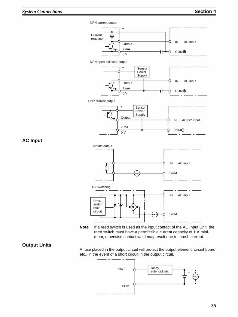
+
COM
NPN current output
IN DC input
0 V
Output
7 mA
Current regulator
+
COM
NPN open-collector output
SensorPowerSupply
IN DC input
0 V
Output
7 mA
+
COM
PNP current output
SensorPowerSupply
IN AC/DC input
0 V
Output
7 mA
AC Input
COM
Contact output
IN AC input
COM
AC Switching
IN AC input
Prox.switchmaincircuit
Note If a reed switch is used as the input contact of the AC Input Unit, thereed switch must have a permissible current capacity of 1 A mini-mum, otherwise contact weld may result due to inrush current.
Output UnitsA fuse placed in the output circuit will protect the output element, circuit board,etc., in the event of a short circuit in the output circuit.
COM
OUT Relay,solenoid, etc. +

37
SECTION 5Installation Environment
5-1 Cooling . . . . . . . . . . . . . . . . . . . . . . . . . . . . . . . . . . . . . . . . . . . . . . . . . . . . . . . . . . . . . . . . . 5-2 Mounting Requirements . . . . . . . . . . . . . . . . . . . . . . . . . . . . . . . . . . . . . . . . . . . . . . . . . . . . 5-3 Duct Work . . . . . . . . . . . . . . . . . . . . . . . . . . . . . . . . . . . . . . . . . . . . . . . . . . . . . . . . . . . . . . 5-4 Preventing Noise . . . . . . . . . . . . . . . . . . . . . . . . . . . . . . . . . . . . . . . . . . . . . . . . . . . . . . . . .
!
Section 5Installation Environment
38
IntroductionThis section details the necessary environment and conditions for installationof the PC. For specific instructions on mounting Units and wiring for I/O andpower, refer to Section 3-3 System Configurations and 4-2 I/O Connections.
Caution Static electricity can cause damage to PC components. Your body can carry anelectrostatic charge, especially when the humidity is low. Before touching the PCbe sure to first touch a grounded metallic object, such as a water pipe, in order todischarge any static build-up.
5-1 CoolingThere are two points to consider in order to ensure that the PC does notoverheat. The first is the clearance between the Racks, and the second isinstallation of a cooling fan.
Clearance BetweenRacks
The Racks need to have sufficient room between each other to allow for I/Owiring, and additional room to ensure that the I/O wiring does not hampercooling. However, the Racks must be mounted so that the length of the con-necting cable does not exceed 2 m, and the total length of the ConnectingCables between all Racks does not exceed 12 m. For details about cablelengths, refer to Appendix C Standard Models. As a general rule, about 70 to120 mm should be left between any two Racks.
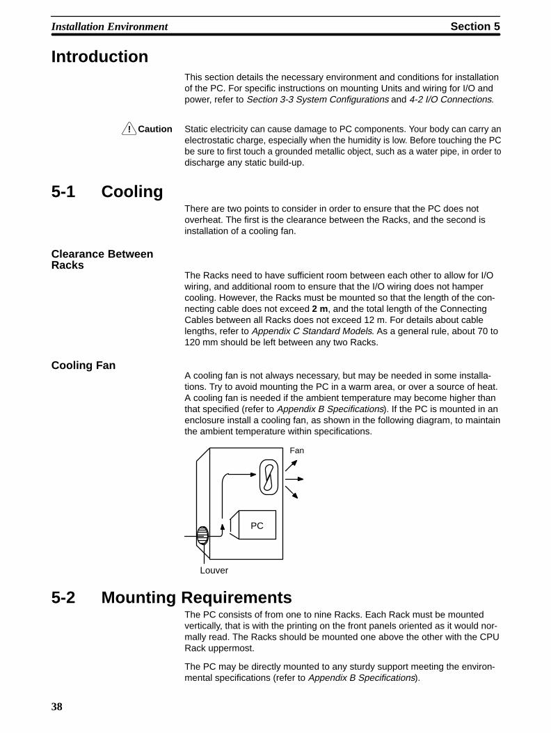
Cooling FanA cooling fan is not always necessary, but may be needed in some installa-tions. Try to avoid mounting the PC in a warm area, or over a source of heat.A cooling fan is needed if the ambient temperature may become higher thanthat specified (refer to Appendix B Specifications). If the PC is mounted in anenclosure install a cooling fan, as shown in the following diagram, to maintainthe ambient temperature within specifications.
PC
Fan
Louver
5-2 Mounting RequirementsThe PC consists of from one to nine Racks. Each Rack must be mountedvertically, that is with the printing on the front panels oriented as it would nor-mally read. The Racks should be mounted one above the other with the CPURack uppermost.
The PC may be directly mounted to any sturdy support meeting the environ-mental specifications (refer to Appendix B Specifications).
Section 5Installation Environment
39
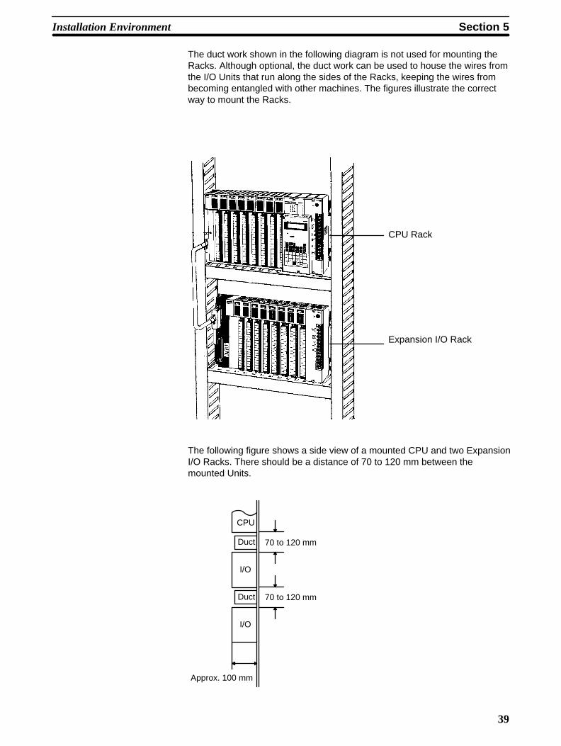
The duct work shown in the following diagram is not used for mounting theRacks. Although optional, the duct work can be used to house the wires fromthe I/O Units that run along the sides of the Racks, keeping the wires frombecoming entangled with other machines. The figures illustrate the correctway to mount the Racks.
CPU Rack
Expansion I/O Rack
The following figure shows a side view of a mounted CPU and two ExpansionI/O Racks. There should be a distance of 70 to 120 mm between themounted Units.
CPU
Duct
I/O
70 to 120 mm
Approx. 100 mm
Duct
I/O
70 to 120 mm
Section 5Installation Environment
40
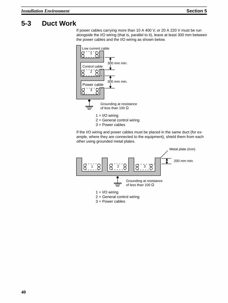
5-3 Duct WorkIf power cables carrying more than 10 A 400 V, or 20 A 220 V must be runalongside the I/O wiring (that is, parallel to it), leave at least 300 mm betweenthe power cables and the I/O wiring as shown below.
Low current cable
Control cable
Power cable
300 mm min.
300 mm min.
1
2
3
Grounding at resistanceof less than 100 Ω
1 = I/O wiring2 = General control wiring3 = Power cables
If the I/O wiring and power cables must be placed in the same duct (for ex-ample, where they are connected to the equipment), shield them from eachother using grounded metal plates.
Metal plate (iron)
1 2 3
200 mm min.
Grounding at resistanceof less than 100 Ω
1 = I/O wiring2 = General control wiring3 = Power cables
Section 5Installation Environment
41
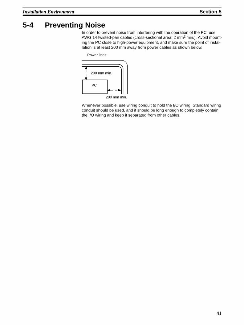
5-4 Preventing NoiseIn order to prevent noise from interfering with the operation of the PC, useAWG 14 twisted-pair cables (cross-sectional area: 2 mm2 min.). Avoid mount-ing the PC close to high-power equipment, and make sure the point of instal-lation is at least 200 mm away from power cables as shown below.
PC
200 mm min.
200 mm min.
Power lines
Whenever possible, use wiring conduit to hold the I/O wiring. Standard wiringconduit should be used, and it should be long enough to completely containthe I/O wiring and keep it separated from other cables.

43
SECTION 6Power Considerations
Section 6Power Considerations
44
IntroductionUse a commercially available 100 to 120 VAC, 200 to 240 VAC, or 24 VDCpower source, according to the PC you are using (refer to Appendix B Speci-fications). Expansion I/O Racks, if used, must also be connected to thepower source. If possible, use independent power sources for the PC, inputdevices, and output devices. All Racks of the PC may be connected to onepower source.
GroundingThe Line Ground (LG) terminal is a noise-filtered neutral terminal that doesnot normally require grounding. If electrical noise is a problem, however, thisterminal should be connected to the Ground (GR) terminal.
To avoid electrical shock, attach a grounded (earth ground) AWG 14 wire(cross-sectional area: 2 mm2 min.) to the GR terminal. The resistance toground must be less than 100 Ω. Do not use a wire longer than 20 m. Caremust be taken, because ground resistance is affected by environmental con-ditions such as soil composition, water content, time of year, and the lengthof time since the wire was laid underground.
PC operation may be adversely affected if the ground wire is shared withother equipment, or if the ground wire is attached to the metal structure of abuilding. When using an Expansion I/O Rack, the Rack must also begrounded to the GR terminal. The same ground can be used for all connec-tions.
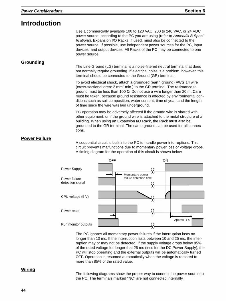
Power FailureA sequential circuit is built into the PC to handle power interruptions. Thiscircuit prevents malfunctions due to momentary power loss or voltage drops.A timing diagram for the operation of this circuit is shown below.
Momentary powerfailure detection time
Approx. 1 s
Power Supply
Power failuredetection signal
CPU voltage (5 V)
Power reset
Run monitor outputs
OFF ON
The PC ignores all momentary power failures if the interruption lasts nolonger than 10 ms. If the interruption lasts between 10 and 25 ms, the inter-ruption may or may not be detected. If the supply voltage drops below 85%of the rated voltage for longer that 25 ms (less for the DC Power Supply), thePC will stop operating and the external outputs will be automatically turnedOFF. Operation is resumed automatically when the voltage is restored tomore than 85% of the rated value.
WiringThe following diagrams show the proper way to connect the power source tothe PC. The terminals marked “NC” are not connected internally.

Section 6Power Considerations
45
AC Connections
-
+
-
+
1:1 isolationtransformer
Screw (4 mm head withselfraising pressure plate)
Voltage selectorShort: 100 to 120 VACOpen: 200 to 240 VACShort-circuit these termi-nals with the shortingbracket supplied as anaccessory to select 100to 120 VAC supply volt-age. For 200 to 240 VACleave them open.
Isolation transformer• Noise between the PCand ground can be sig-nificantly reduced byconnecting a 1-to-1 iso-lation transformer. Donot ground the secon-dary coil of the trans-former.
Power line• Use AWG 14 twisted-pair cable (cross-sec-tional area: 2 mm2 min.)
Breaker
AC power source
• Supply 100 to 120or 200 to 240 VAC• Keep voltage fluc-tuations within thespecified range (referto Appendix B Speci-fications)
Voltage selectorShort: 100 to 120 VACOpen: 200 to 240 VACShort-circuit these terminalswith the shorting bracketsupplied as an accessory toselect 100 to 120 VAC sup-ply voltage. For 200 to 240VAC, leave them open.
Screw (4 mm head withselfraising pressure plate)
3G2A5-PS221-E/223-E
3G2A5-PS222-E
8.6 mm max.
Be sure to use a wire of at least 1.25 mm2 inthickness.Use M4 screws for tightening crimp termi-nals. Use ring crimp terminals for wiring. Donot connect bare stranded wires directly toterminal blocks.
Caution Tighten the screws on the terminal block of the ACPower Supply Unit to a torque of 1.2 N m. Loosescrews may result in burning or malfunction.
!
Section 6Power Considerations
46
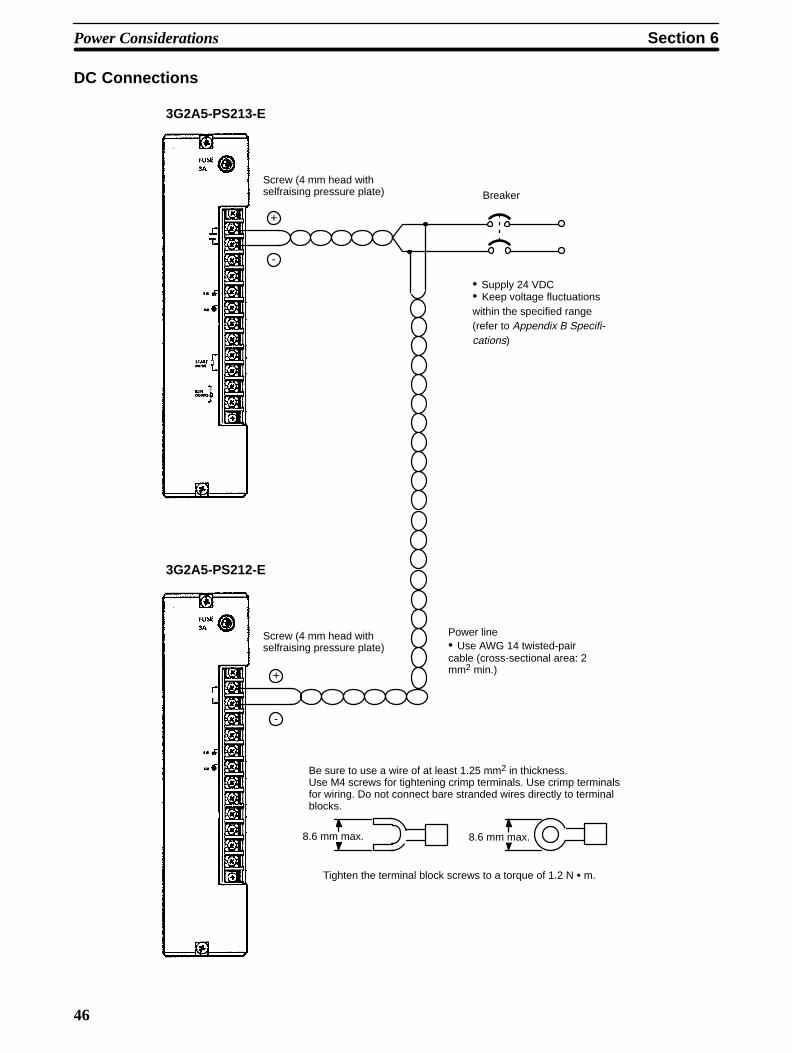
DC Connections
Screw (4 mm head withselfraising pressure plate)
z
Power line• Use AWG 14 twisted-paircable (cross-sectional area: 2mm2 min.)
• Supply 24 VDC• Keep voltage fluctuationswithin the specified range(refer to Appendix B Specifi-cations)
Screw (4 mm head withselfraising pressure plate)
3G2A5-PS212-E
3G2A5-PS213-E
-
+
-
+
Breaker
8.6 mm max.8.6 mm max.
Be sure to use a wire of at least 1.25 mm2 in thickness.Use M4 screws for tightening crimp terminals. Use crimp terminalsfor wiring. Do not connect bare stranded wires directly to terminalblocks.
Tighten the terminal block screws to a torque of 1.2 N m.
!
Section 6Power Considerations
47
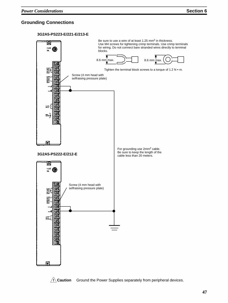
Grounding Connections
Screw (4 mm head withselfraising pressure plate)
3G2A5-PS223-E/221-E/213-E
3G2A5-PS222-E/212-E
Screw (4 mm head withselfraising pressure plate)
For grounding use 2mm2 cable.Be sure to keep the length of thecable less than 20 meters.
8.6 mm max.8.6 mm max.
Be sure to use a wire of at least 1.25 mm2 in thickness.Use M4 screws for tightening crimp terminals. Use crimp terminalsfor wiring. Do not connect bare stranded wires directly to terminalblocks.
Tighten the terminal block screws to a torque of 1.2 N m.
Caution Ground the Power Supplies separately from peripheral devices.

49
SECTION 7Safety Considerations
Section 7Safety Considerations
50
IntroductionThere are certain safety requirements to be considered when installing thePC. Some of these, such as the emergency stop circuit (refer to Power Sup-ply), are part of the initial wiring. The considerations described below shouldbe kept in mind when operating the PC and when connecting I/O devices tothe PC.
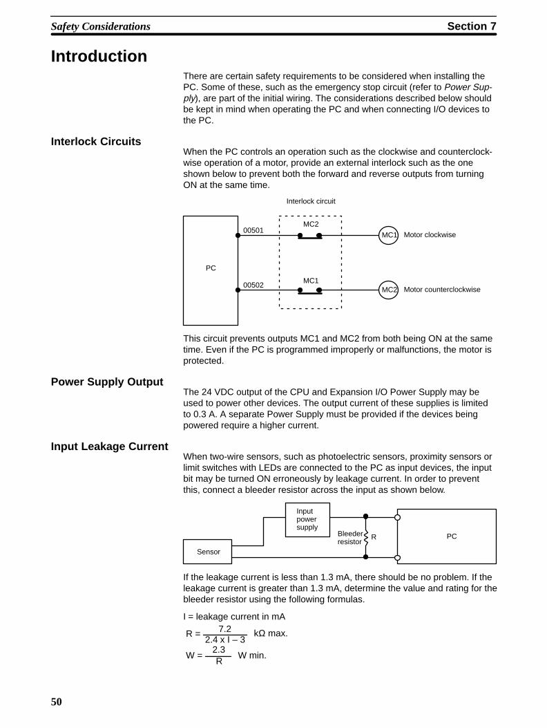
Interlock CircuitsWhen the PC controls an operation such as the clockwise and counterclock-wise operation of a motor, provide an external interlock such as the oneshown below to prevent both the forward and reverse outputs from turningON at the same time.
PC
MC2
MC1
00501
00502
MC1
MC2
Motor clockwise
Motor counterclockwise
Interlock circuit
This circuit prevents outputs MC1 and MC2 from both being ON at the sametime. Even if the PC is programmed improperly or malfunctions, the motor isprotected.
Power Supply OutputThe 24 VDC output of the CPU and Expansion I/O Power Supply may beused to power other devices. The output current of these supplies is limitedto 0.3 A. A separate Power Supply must be provided if the devices beingpowered require a higher current.
Input Leakage CurrentWhen two-wire sensors, such as photoelectric sensors, proximity sensors orlimit switches with LEDs are connected to the PC as input devices, the inputbit may be turned ON erroneously by leakage current. In order to preventthis, connect a bleeder resistor across the input as shown below.
Sensor
Inputpowersupply
Bleeder resistor
R PC
If the leakage current is less than 1.3 mA, there should be no problem. If theleakage current is greater than 1.3 mA, determine the value and rating for thebleeder resistor using the following formulas.
I = leakage current in mA7.2
2.4 x I – 3R = kΩ max.
W =2.3R
W min.
Section 7Safety Considerations
51
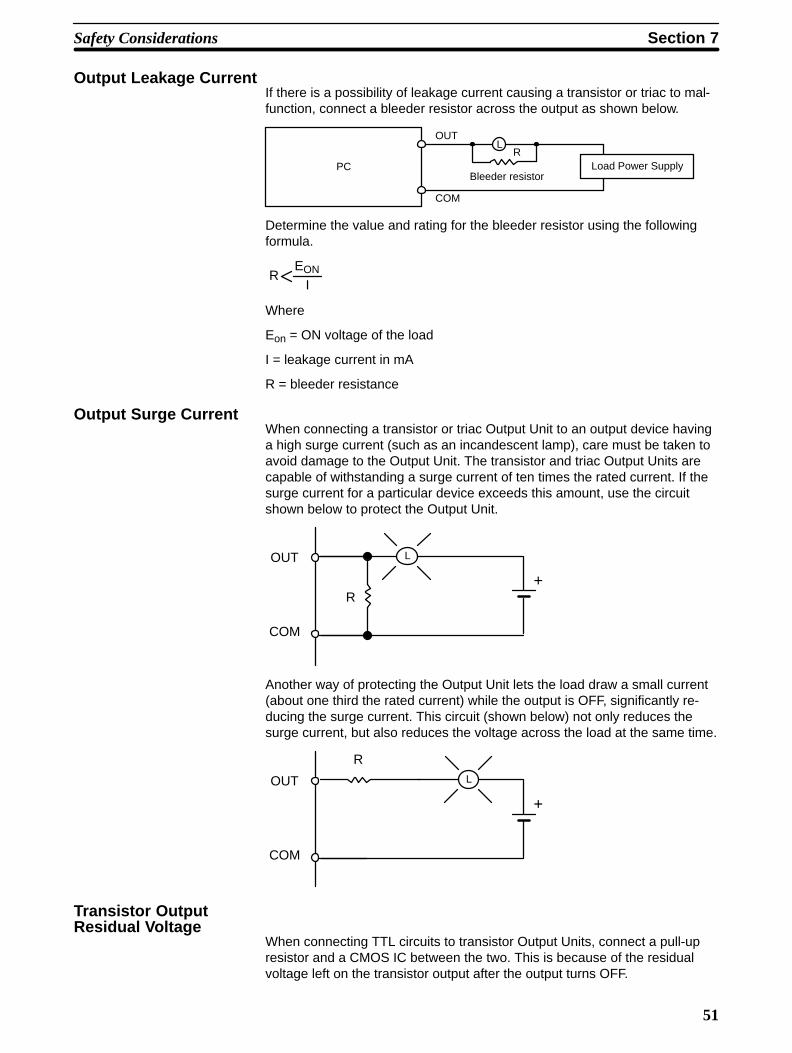
Output Leakage CurrentIf there is a possibility of leakage current causing a transistor or triac to mal-function, connect a bleeder resistor across the output as shown below.
PC Load Power Supply
OUT
COM
Bleeder resistor
LR
Determine the value and rating for the bleeder resistor using the followingformula.
EON
IR
Where
Eon = ON voltage of the load
I = leakage current in mA
R = bleeder resistance
Output Surge CurrentWhen connecting a transistor or triac Output Unit to an output device havinga high surge current (such as an incandescent lamp), care must be taken toavoid damage to the Output Unit. The transistor and triac Output Units arecapable of withstanding a surge current of ten times the rated current. If thesurge current for a particular device exceeds this amount, use the circuitshown below to protect the Output Unit.
R
L
+
OUT
COM
Another way of protecting the Output Unit lets the load draw a small current(about one third the rated current) while the output is OFF, significantly re-ducing the surge current. This circuit (shown below) not only reduces thesurge current, but also reduces the voltage across the load at the same time.
RL
+
OUT
COM
Transistor OutputResidual Voltage
When connecting TTL circuits to transistor Output Units, connect a pull-upresistor and a CMOS IC between the two. This is because of the residualvoltage left on the transistor output after the output turns OFF.
Section 7Safety Considerations
52
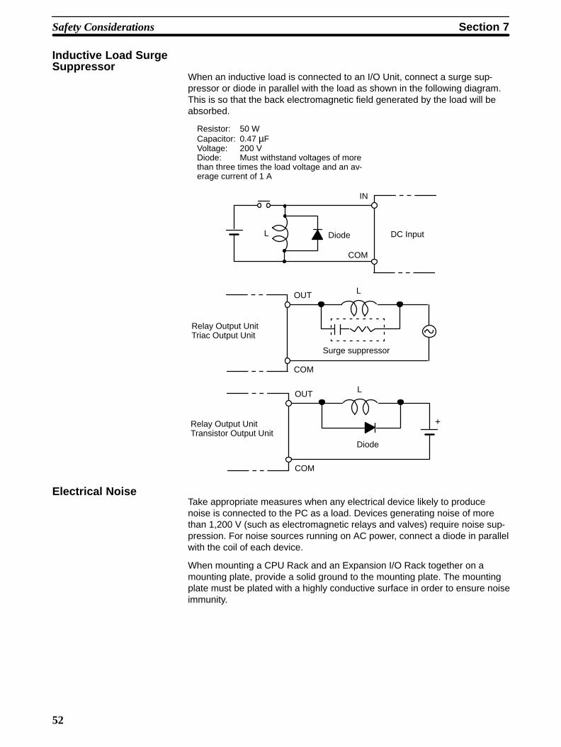
Inductive Load SurgeSuppressor
When an inductive load is connected to an I/O Unit, connect a surge sup-pressor or diode in parallel with the load as shown in the following diagram.This is so that the back electromagnetic field generated by the load will beabsorbed.
Relay Output UnitTransistor Output Unit
LOUT
COM
Surge suppressor
LOUT
COM
Relay Output UnitTriac Output Unit
+
Diode
L
IN
COM
Diode DC Input
Resistor: 50 WCapacitor: 0.47 µFVoltage: 200 VDiode: Must withstand voltages of morethan three times the load voltage and an av-erage current of 1 A
Electrical NoiseTake appropriate measures when any electrical device likely to producenoise is connected to the PC as a load. Devices generating noise of morethan 1,200 V (such as electromagnetic relays and valves) require noise sup-pression. For noise sources running on AC power, connect a diode in parallelwith the coil of each device.
When mounting a CPU Rack and an Expansion I/O Rack together on amounting plate, provide a solid ground to the mounting plate. The mountingplate must be plated with a highly conductive surface in order to ensure noiseimmunity.

53
Appendices
A Inspection and Maintenance . . . . . . . . . . . . . . . . . . . . . . . . . . . . . . . . . . . . . . . . . . . . . . . . . . . . B Specifications . . . . . . . . . . . . . . . . . . . . . . . . . . . . . . . . . . . . . . . . . . . . . . . . . . . . . . . . . . . . . . . C Standard Models . . . . . . . . . . . . . . . . . . . . . . . . . . . . . . . . . . . . . . . . . . . . . . . . . . . . . . . . . . . .
54
A Inspection and Maintenance
Certain consumable items in a PC (such as fuses, relays, or batteries) needoccasional replacement. This Appendix explains how to replace each ofthese items. Refer to Appendix B Specifications for the specifications of indi-vidual consumable items. Always keep spare items on hand so that they canbe used as immediate replacements.
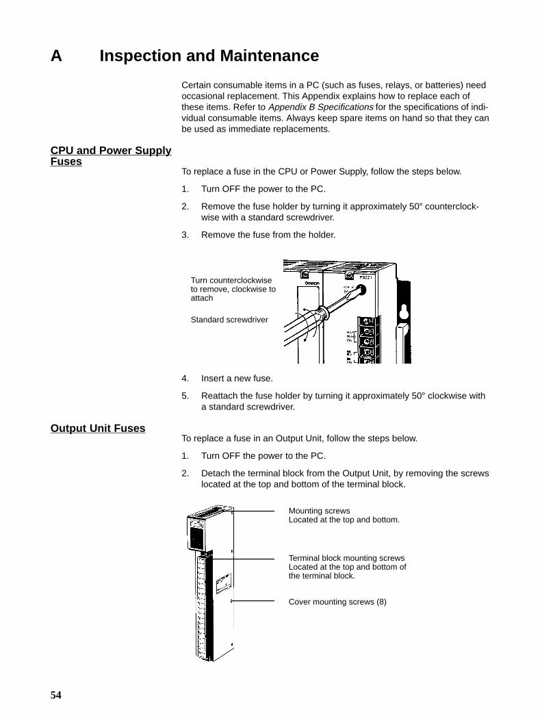
CPU and Power SupplyFuses
To replace a fuse in the CPU or Power Supply, follow the steps below.
1. Turn OFF the power to the PC.
2. Remove the fuse holder by turning it approximately 50° counterclock-wise with a standard screwdriver.
3. Remove the fuse from the holder.
Turn counterclockwiseto remove, clockwise toattach
Standard screwdriver
4. Insert a new fuse.
5. Reattach the fuse holder by turning it approximately 50° clockwise witha standard screwdriver.
Output Unit FusesTo replace a fuse in an Output Unit, follow the steps below.
1. Turn OFF the power to the PC.
2. Detach the terminal block from the Output Unit, by removing the screwslocated at the top and bottom of the terminal block.
Mounting screwsLocated at the top and bottom.
Terminal block mounting screwsLocated at the top and bottom ofthe terminal block.
Cover mounting screws (8)
Appendix AInspection and Maintenance
55
3. Remove the screws that mount the Output Unit to the Backplane. Pullingthe Unit toward you, remove the Output Unit from the Backplane.
4. There are eight screws on each side of the Output Unit. Remove thesescrews to detach the case from the cover.
5. Pull out the printed circuit board.
6. Insert a new fuse.
7. Reassemble in reverse order.
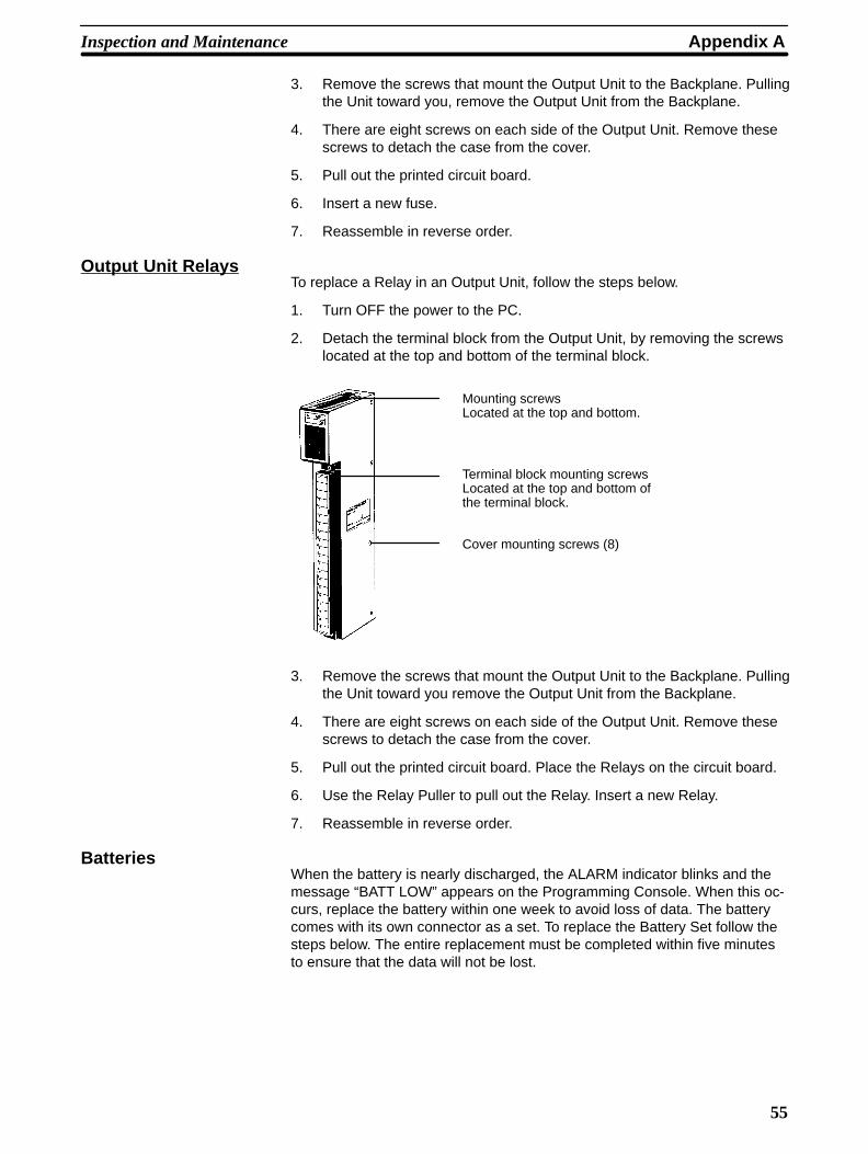
Output Unit RelaysTo replace a Relay in an Output Unit, follow the steps below.
1. Turn OFF the power to the PC.
2. Detach the terminal block from the Output Unit, by removing the screwslocated at the top and bottom of the terminal block.
Mounting screwsLocated at the top and bottom.
Terminal block mounting screwsLocated at the top and bottom ofthe terminal block.
Cover mounting screws (8)
3. Remove the screws that mount the Output Unit to the Backplane. Pullingthe Unit toward you remove the Output Unit from the Backplane.
4. There are eight screws on each side of the Output Unit. Remove thesescrews to detach the case from the cover.
5. Pull out the printed circuit board. Place the Relays on the circuit board.
6. Use the Relay Puller to pull out the Relay. Insert a new Relay.
7. Reassemble in reverse order.
BatteriesWhen the battery is nearly discharged, the ALARM indicator blinks and themessage “BATT LOW” appears on the Programming Console. When this oc-curs, replace the battery within one week to avoid loss of data. The batterycomes with its own connector as a set. To replace the Battery Set follow thesteps below. The entire replacement must be completed within five minutesto ensure that the data will not be lost.
Inspection and Maintenance Appendix A
56
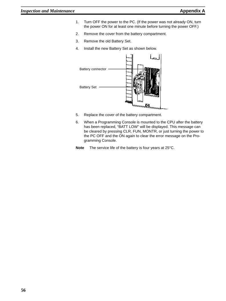
1. Turn OFF the power to the PC. (If the power was not already ON, turnthe power ON for at least one minute before turning the power OFF.)
2. Remove the cover from the battery compartment.
3. Remove the old Battery Set.
4. Install the new Battery Set as shown below.
Battery connector
Battery Set
5. Replace the cover of the battery compartment.
6. When a Programming Console is mounted to the CPU after the batteryhas been replaced, “BATT LOW” will be displayed. This message canbe cleared by pressing CLR, FUN, MONTR, or just turning the power tothe PC OFF and the ON again to clear the error message on the Pro-gramming Console.
Note The service life of the battery is four years at 25°C.
57
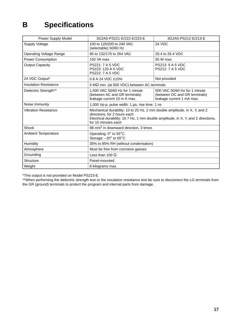
B Specifications
Power Supply Model 3G2A5-PS221-E/222-E/223-E 3G2A5-PS212-E/213-E
Supply Voltage 100 to 120/200 to 240 VAC(selectable) 50/60 Hz
24 VDC
Operating Voltage Range 85 to 132/170 to 264 VAC 20.4 to 26.4 VDC
Power Consumption 150 VA max. 55 W max.
Output Capacity PS221: 7 A 5 VDCPS223: 120 A 5 VDCPS222: 7 A 5 VDC
PS213: 9 A 5 VDCPS212: 7 A 5 VDC
24 VDC Output* 0.8 A 24 VDC ±10% Not provided
Insulation Resistance 5 MΩ min. (at 500 VDC) between AC terminals
Dielectric Strength** 1,500 VAC 50/60 Hz for 1 minute(between AC and GR terminals)leakage current 10 m A max.
500 VAC 50/60 Hz for 1 minute(between DC and GR terminals)leakage current 1 mA max.
Noise Immunity 1,000 Vp-p, pulse width: 1 µs, rise time: 1 ns
Vibration Resistance Mechanical durability: 10 to 25 Hz, 2 mm double amplitude, in X, Y, and Zdirections, for 2 hours eachElectrical durability: 16.7 Hz, 1 mm double amplitude, in X, Y, and Z directions,for 10 minutes each
Shock 98 m/s2 in downward direction, 3 times
Ambient Temperature Operating: 0° to 55°CStorage: –20° to 65°C
Humidity 35% to 85% RH (without condensation)
Atmosphere Must be free from corrosive gasses
Grounding Less than 100 ΩStructure Panel-mounted
Weight 8 kilograms max.
*This output is not provided on Model PS223-E.**When performing the dielectric strength test or the insulation resistance test be sure to disconnect the LG terminals fromthe GR (ground) terminals to protect the program and internal parts from damage.
Appendix BSpecifications
58
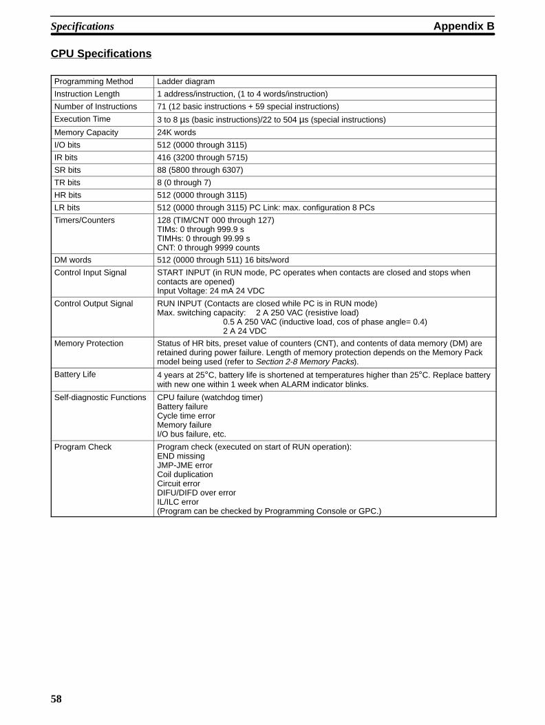
CPU Specifications
Programming Method Ladder diagram
Instruction Length 1 address/instruction, (1 to 4 words/instruction)
Number of Instructions 71 (12 basic instructions + 59 special instructions)
Execution Time 3 to 8 µs (basic instructions)/22 to 504 µs (special instructions)
Memory Capacity 24K words
I/O bits 512 (0000 through 3115)
IR bits 416 (3200 through 5715)
SR bits 88 (5800 through 6307)
TR bits 8 (0 through 7)
HR bits 512 (0000 through 3115)
LR bits 512 (0000 through 3115) PC Link: max. configuration 8 PCs
Timers/Counters 128 (TIM/CNT 000 through 127)TIMs: 0 through 999.9 sTIMHs: 0 through 99.99 sCNT: 0 through 9999 counts
DM words 512 (0000 through 511) 16 bits/word
Control Input Signal START INPUT (in RUN mode, PC operates when contacts are closed and stops whencontacts are opened)Input Voltage: 24 mA 24 VDC
Control Output Signal RUN INPUT (Contacts are closed while PC is in RUN mode)Max. switching capacity: 2 A 250 VAC (resistive load)
0.5 A 250 VAC (inductive load, cos of phase angle= 0.4)2 A 24 VDC
Memory Protection Status of HR bits, preset value of counters (CNT), and contents of data memory (DM) areretained during power failure. Length of memory protection depends on the Memory Packmodel being used (refer to Section 2-8 Memory Packs).
Battery Life 4 years at 25°C, battery life is shortened at temperatures higher than 25°C. Replace batterywith new one within 1 week when ALARM indicator blinks.
Self-diagnostic Functions CPU failure (watchdog timer)Battery failureCycle time errorMemory failureI/O bus failure, etc.
Program Check Program check (executed on start of RUN operation):END missingJMP-JME errorCoil duplicationCircuit errorDIFU/DIFD over errorIL/ILC error(Program can be checked by Programming Console or GPC.)

Specifications Appendix B
59
DC Input Units
3G2A5-ID112 3G2A5-ID213
Input Voltage 5 to 12 VAC10%/15% 12 to 24 VAC10%/15%
Input Impedance 560 Ω 2.2 kΩInput Current 16 mA typical (at 12 VDC) 10 mA typical (at 24 VDC)
ON Voltage 4.0 VDC min. 10.2 VDC min.
OFF Voltage 1.5 VDC max. 3.0 VDC max.
ON ResponseTime
1.5 ms max. 1.5 ms max.
OFF ResponseTime
1.5 ms max. 1.5 ms max.
No. of Points 16 (8 points/common, 2 circuits) 16 (8 points/common, 2 circuits)
Internal CurrentConsumption
10 mA 5 VDC max. 20 mA 5 VDC max.
Weight 450 grams max. 450 grams max.
CircuitConfiguration
Inter-nalCircuit
COM
COM
IN 00to
IN 06IN 07
IN 08to
IN 14IN 15
6.8kΩ
6.8kΩ
560 Ω
560 Ω
Two-wire sensors cannot be connected.
Inter-nalCircuit
1.8kΩ
1.8kΩ
2.2 kΩ
2.2 kΩ
COM
COM
IN 00to
IN 06IN 07
IN 08to
IN 14IN 15
Inter-nalCircuit
1.8kΩ
1.8kΩ
TerminalConnections
+
COM
NC
0
1
2
3
4
5
6
7
8
9
10
11
12
13
14
15 16171819NC
0123456789101112131415
COM
+5 to 12 VDC
5 to 12 VDC+
COM
NC
0
1
2
3
4
5
6
7
8
9
10
11
12
13
14
15 16171819NC
0123456789101112131415
COM
+12 to 24 VDC
12 to 24 VDC
Dimensions A-shape A-shape
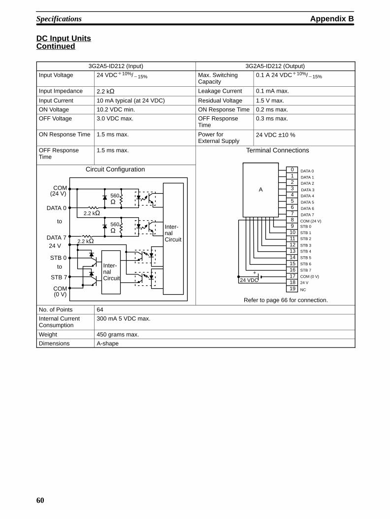
Appendix BSpecifications
60
DC Input UnitsContinued
3G2A5-ID212 (Input) 3G2A5-ID212 (Output)
Input Voltage 24 VDC10%/15% Max. SwitchingCapacity
0.1 A 24 VDC10%/15%
Input Impedance 2.2 kΩ Leakage Current 0.1 mA max.
Input Current 10 mA typical (at 24 VDC) Residual Voltage 1.5 V max.
ON Voltage 10.2 VDC min. ON Response Time 0.2 ms max.
OFF Voltage 3.0 VDC max. OFF ResponseTime
0.3 ms max.
ON Response Time 1.5 ms max. Power forExternal Supply
24 VDC ±10 %
OFF ResponseTime
1.5 ms max. Terminal Connections
Inter-nalCircuit
COM
COM
to
to
560Ω
2.2 kΩ
560Ω
Inter-nalCircuit
2.2 kΩ
(24 V)
DATA 0
DATA 7
STB 0
STB 7
24 V
(0 V)
Circuit Configuration
16171819 NC
0123456789101112131415
+24 VDC
A
DATA 0
DATA 1
DATA 2
DATA 3
DATA 4
DATA 5
DATA 6
DATA 7
COM (24 V)STB 0
STB 1
STB 2
STB 3
STB 4
STB 5
STB 6
STB 7
COM (0 V)
24 V
Refer to page 66 for connection.
No. of Points 64
Internal CurrentConsumption
300 mA 5 VDC max.
Weight 450 grams max.
Dimensions A-shape

Specifications Appendix B
61
DC Input Units Continued3G2A5-ID215 3G2A5-ID218
Input Voltage 12 to 24 VDC10%/15%
Input Impedance 2.2 kΩInput Current 10 mA typical (at 24 VDC)
ON Voltage 10.2 VDC min.
OFF Voltage 3.0 VDC max.
ON Response Time 15 ms max. 1.5 ms max.
OFF Response Time 15 ms max. 1.5 ms max.
No. of Points 32 (8 points/common, 4 circuits)
Internal CurrentConsumption
160 mA 5 VDC max.
Weight 450 grams max.
CircuitConfiguration
COM
COM
IN 00to
IN 07
IN 15
IN 08to
COM
COM
IN 00to
IN 07
IN 15
IN 08to
Inter-nalCircuit
2.2 kΩ
ID215: 680 ΩID218: 750 Ω
2.2 kΩ
I
II
ID215: 680 ΩID218: 750 Ω
Terminal Connections
+
COM
NC
0
1
2
3
4
5
6
7
8
9
10
11
12
13
14
15 161718
0123456789101112131415
COM
to 24 VDC
+to 24 VDC
+
COM
NC
0
1
2
3
4
5
6
7
8
9
10
11
12
13
14
15161718
0123456789101112131415
COM
12 to 24 VDC
+12 to 24 VDC
A B
+
+ +
+
I II
Dimensions B-shape
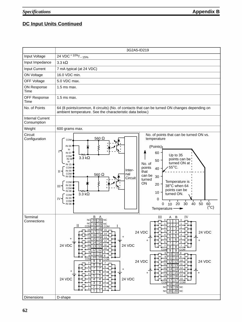
Appendix BSpecifications
62
DC Input Units Continued
3G2A5-ID219
Input Voltage 24 VDC10%/15%
Input Impedance 3.3 kΩInput Current 7 mA typical (at 24 VDC)
ON Voltage 16.0 VDC min.
OFF Voltage 5.0 VDC max.
ON ResponseTime
1.5 ms max.
OFF ResponseTime
1.5 ms max.
No. of Points 64 (8 points/common, 8 circuits) (No. of contacts that can be turned ON changes depending onambient temperature. See the characteristic data below.)
Internal CurrentConsumption
Weight 600 grams max.
CircuitConfiguration
Inter-nalCircuit
COM
COM
IN 00
to
IN 07
IN 15
3.3 kΩ
560 Ω
IN 08
to
3.3 kΩ
560 Ω
COMIN 00COMIN 08
I
II
III
IV
COMIN 00COMIN 08
COMIN 00COMIN 08
0
10
20
30
40
50
60
0 10 20 30 40 50 60
(Points)
(°C)Temperature
No. ofpointsthatcan beturnedON
No. of points that can be turned ON vs.temperature
Up to 35points can beturned ON at55°C.
Temperature is38°C when 64points can beturned ON.
TerminalConnections
161718
131415
1920
161718
131415
1920
+
NC
0
1
2
3
4
5
6
7
8
9
10
11
12
13
14
15
COM
+
A B123456789101112
123456789101112
COM
NC
+
NC
0
1
2
3
4
5
6
7
8
9
10
11
12
13
14
15
COM
+
COM
NC
+
NC
0
1
2
3
4
5
6
7
8
9
10
11
12
13
14
15
COM
+
AB
161718
123456789101112131415
1920
161718
123456789101112131415
1920
COM
NC
+
NC
0
1
2
3
4
5
6
7
8
9
10
11
12
13
14
15
COM
+
COM
NC
24 VDC
24 VDC
24 VDC
24 VDC 24 VDC
24 VDC
III
III IV
24 VDC
24 VDC
Dimensions D-shape
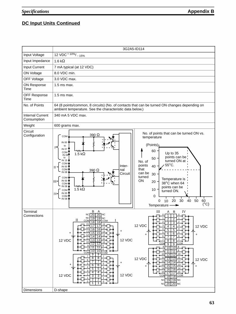
Specifications Appendix B
63
DC Input Units Continued
3G2A5-ID114
Input Voltage 12 VDC10%/15%
Input Impedance 1.6 kΩInput Current 7 mA typical (at 12 VDC)
ON Voltage 8.0 VDC min.
OFF Voltage 3.0 VDC max.
ON ResponseTime
1.5 ms max.
OFF ResponseTime
1.5 ms max.
No. of Points 64 (8 points/common, 8 circuits) (No. of contacts that can be turned ON changes depending onambient temperature. See the characteristic data below.)
Internal CurrentConsumption
340 mA 5 VDC max.
Weight 600 grams max.
CircuitConfiguration
Inter-nalCircuit
COM
COM
IN 00
to
IN 07
IN 15
1.5 kΩ
390 Ω
IN 08
to
1.5 kΩ
390 Ω
COMIN 00COMIN 08
I
II
III
IV
COMIN 00COMIN 08
COMIN 00COMIN 08
0
10
20
30
40
50
60
0 10 20 30 40 50 60
(Points)
(°C)Temperature
No. ofpointsthatcan beturnedON
No. of points that can be turned ON vs.temperature
Up to 35points can beturned ON at55°C.
Temperature is38°C when 64points can beturned ON.
TerminalConnections
161718
131415
1920
161718
131415
1920
+
NC
0
1
2
3
4
5
6
7
8
9
10
11
12
13
14
15
COM
+
A B123456789101112
123456789101112
COM
NC
+
NC
0
1
2
3
4
5
6
7
8
9
10
11
12
13
14
15
COM
+
COM
NC
+
NC
0
1
2
3
4
5
6
7
8
9
10
11
12
13
14
15
COM
+
AB
161718
123456789101112131415
1920
161718
123456789101112131415
1920
COM
NC
+
NC
0
1
2
3
4
5
6
7
8
9
10
11
12
13
14
15
COM
+
COM
NCIII IV
12 VDC
III
12 VDC
12 VDC
12 VDC
12 VDC
12 VDC
12 VDC
12 VDC
Dimensions D-shape
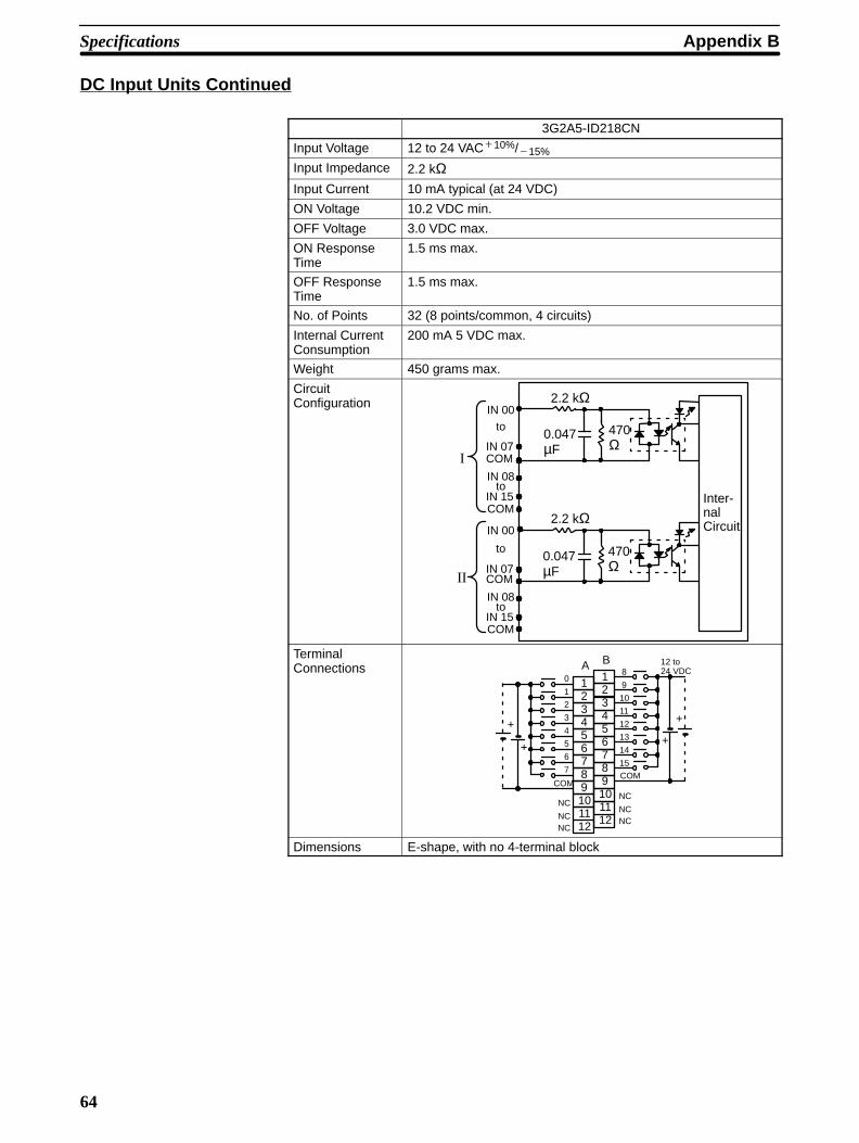
Appendix BSpecifications
64
DC Input Units Continued
3G2A5-ID218CN
Input Voltage 12 to 24 VAC10%/15%
Input Impedance 2.2 kΩInput Current 10 mA typical (at 24 VDC)
ON Voltage 10.2 VDC min.
OFF Voltage 3.0 VDC max.
ON ResponseTime
1.5 ms max.
OFF ResponseTime
1.5 ms max.
No. of Points 32 (8 points/common, 4 circuits)
Internal CurrentConsumption
200 mA 5 VDC max.
Weight 450 grams max.
CircuitConfiguration
Inter-nalCircuit
COM
COM
IN 00to
IN 07
IN 15
2.2 kΩ
2.2 kΩ
IN 08to
COM
COM
IN 00
to
IN 07
IN 15
IN 08to
0.047µF
0.047µF
470Ω
470Ω
I
II
TerminalConnections
+
0
1
2
3
4
5
6
7
123456789101112
COM
NC
8
9
10
11
12
13
14
15
123456789101112
COM
A B
++
+
NCNC
NC
NCNC
12 to24 VDC
Dimensions E-shape, with no 4-terminal block
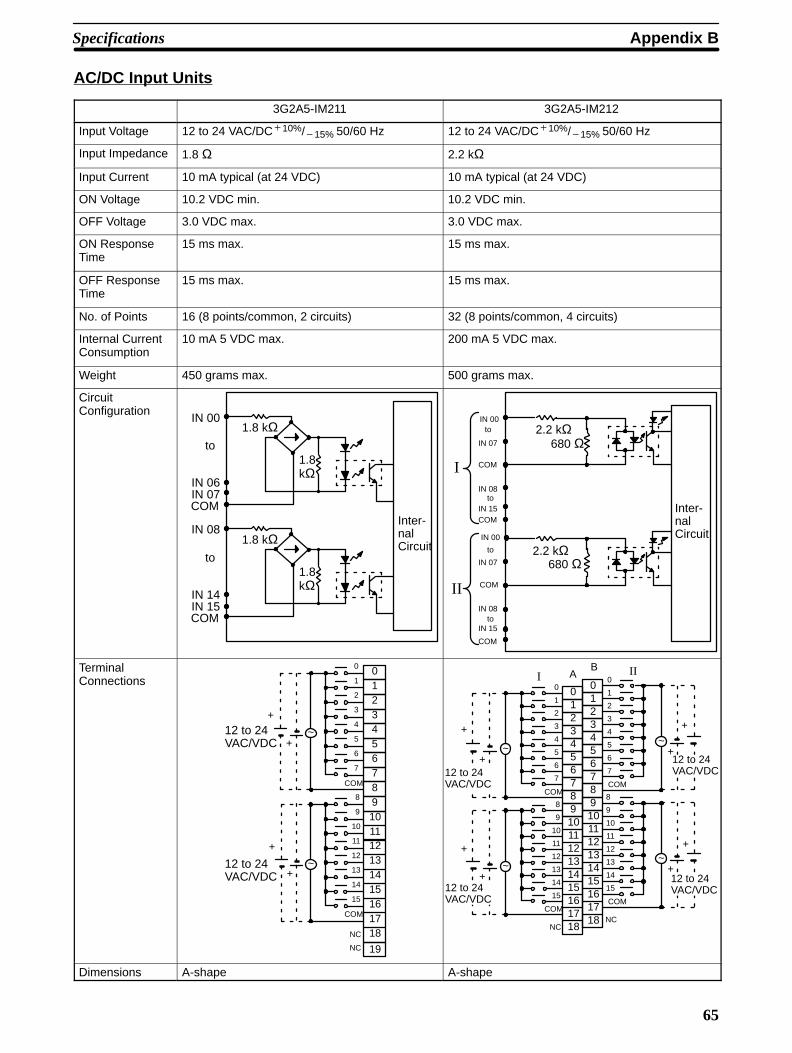
Specifications Appendix B
65
AC/DC Input Units
3G2A5-IM211 3G2A5-IM212
Input Voltage 12 to 24 VAC/DC10%/15% 50/60 Hz 12 to 24 VAC/DC10%/15% 50/60 Hz
Input Impedance 1.8 Ω 2.2 kΩ
Input Current 10 mA typical (at 24 VDC) 10 mA typical (at 24 VDC)
ON Voltage 10.2 VDC min. 10.2 VDC min.
OFF Voltage 3.0 VDC max. 3.0 VDC max.
ON ResponseTime
15 ms max. 15 ms max.
OFF ResponseTime
15 ms max. 15 ms max.
No. of Points 16 (8 points/common, 2 circuits) 32 (8 points/common, 4 circuits)
Internal CurrentConsumption
10 mA 5 VDC max. 200 mA 5 VDC max.
Weight 450 grams max. 500 grams max.
CircuitConfiguration
Inter-nalCircuit
1.8kΩ
1.8 kΩIN 00
IN 06IN 07
to
COM
1.8kΩ
1.8 kΩIN 08
IN 14IN 15
to
COM
Inter-nalCircuit
COM
COM
IN 00to
IN 07
IN 15
2.2 kΩ680 Ω
2.2 kΩ680 Ω
IN 08to
COM
COM
IN 00
to
IN 07
IN 15
IN 08to
I
II
TerminalConnections
~
~
15
COM
+
+
COM
NC
0
1
2
3
4
5
6
7
8
9
10
11
12
13
14
15 161718
01234567891011121314
+
+
19NC
12 to 24VAC/VDC
12 to 24VAC/VDC
12 to 24VAC/VDC
12 to 24VAC/VDC
12 to 24VAC/VDC
12 to 24VAC/VDC
2345
COM
NC
0
1
2
3
4
5
6
7
8
9
10
11
12
13
14
15 161718
01
6789101112131415
COM
COM
NC
0
1
2
3
4
5
6
7
8
9
10
11
12
13
14
15161718
0123456789101112131415
COM
AB III
~+
~+
~
~
+
+
+
+
+
+
Dimensions A-shape A-shape
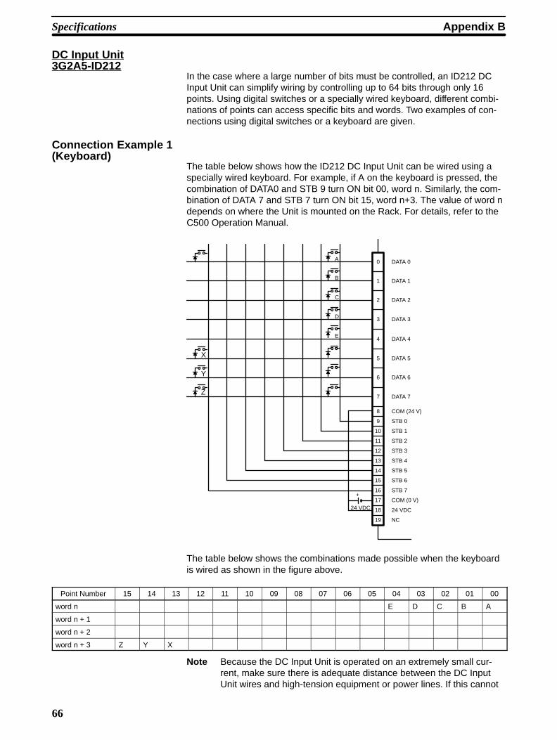
Appendix BSpecifications
66
DC Input Unit3G2A5-ID212
In the case where a large number of bits must be controlled, an ID212 DCInput Unit can simplify wiring by controlling up to 64 bits through only 16points. Using digital switches or a specially wired keyboard, different combi-nations of points can access specific bits and words. Two examples of con-nections using digital switches or a keyboard are given.
Connection Example 1(Keyboard)
The table below shows how the ID212 DC Input Unit can be wired using aspecially wired keyboard. For example, if A on the keyboard is pressed, thecombination of DATA0 and STB 9 turn ON bit 00, word n. Similarly, the com-bination of DATA 7 and STB 7 turn ON bit 15, word n+3. The value of word ndepends on where the Unit is mounted on the Rack. For details, refer to theC500 Operation Manual.
+
0
1
2
3
4
5
6
7
8
9
10
11
12
13
14
15
16
17
18
19
24 VDC
A
B
C
D
E
DATA 0
DATA 1
DATA 2
DATA 3
DATA 4
DATA 5
DATA 6
DATA 7
COM (24 V)
STB 0
STB 1
STB 2
STB 3
STB 4
STB 5
STB 6
STB 7
COM (0 V)
24 VDC
NC
X
Y
Z
The table below shows the combinations made possible when the keyboardis wired as shown in the figure above.
Point Number 15 14 13 12 11 10 09 08 07 06 05 04 03 02 01 00
word n E D C B A
word n + 1
word n + 2
word n + 3 Z Y X
Note Because the DC Input Unit is operated on an extremely small cur-rent, make sure there is adequate distance between the DC InputUnit wires and high-tension equipment or power lines. If this cannot
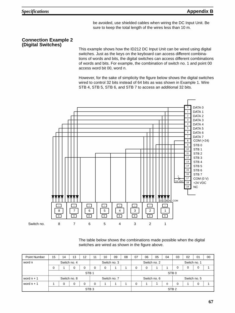
Specifications Appendix B
67
be avoided, use shielded cables when wiring the DC Input Unit. Besure to keep the total length of the wires less than 10 m.
Connection Example 2(Digital Switches)
This example shows how the ID212 DC Input Unit can be wired using digitalswitches. Just as the keys on the keyboard can access different combina-tions of words and bits, the digital switches can access different combinationsof words and bits. For example, the combination of switch no. 1 and point 00access word bit 00, word n.
However, for the sake of simplicity the figure below shows the digital switcheswired to control 32 bits instead of 64 bits as was shown in Example 1. WireSTB 4, STB 5, STB 6, and STB 7 to access an additional 32 bits.
-
+
-
+
-
+
-
+
-
+
-
+
-
+
-
+
8 7 6 5 4 3 2 1
+
0
1
2
3
4
5
6
7
8
9
10
11
12
13
14
15
16
17
18
19
24 VDC
D C B A COM
DATA 0DATA 1DATA 2DATA 3DATA 4DATA 5DATA 6DATA 7COM (+24)
STB 0STB 1STB 2STB 3STB 4STB 5STB 6STB 7COM (0 V)+24 VDCNC
Switch no. 8 7 6 5 4 3 2 1
The table below shows the combinations made possible when the digitalswitches are wired as shown in the figure above.
Point Number 15 14 13 12 11 10 09 08 07 06 05 04 03 02 01 00
word n Switch no. 4 Switch no. 3 Switch no. 2 Switch no. 1
0 1 0 0 0 0 1 1 0 0 1 1 0 0 0 1
STB 1 STB 0
word n + 1 Switch no. 8 Switch no. 7 Switch no. 6 Switch no. 5
word n + 1 1 0 0 0 0 1 1 1 0 1 1 0 0 1 0 1
STB 3 STB 2
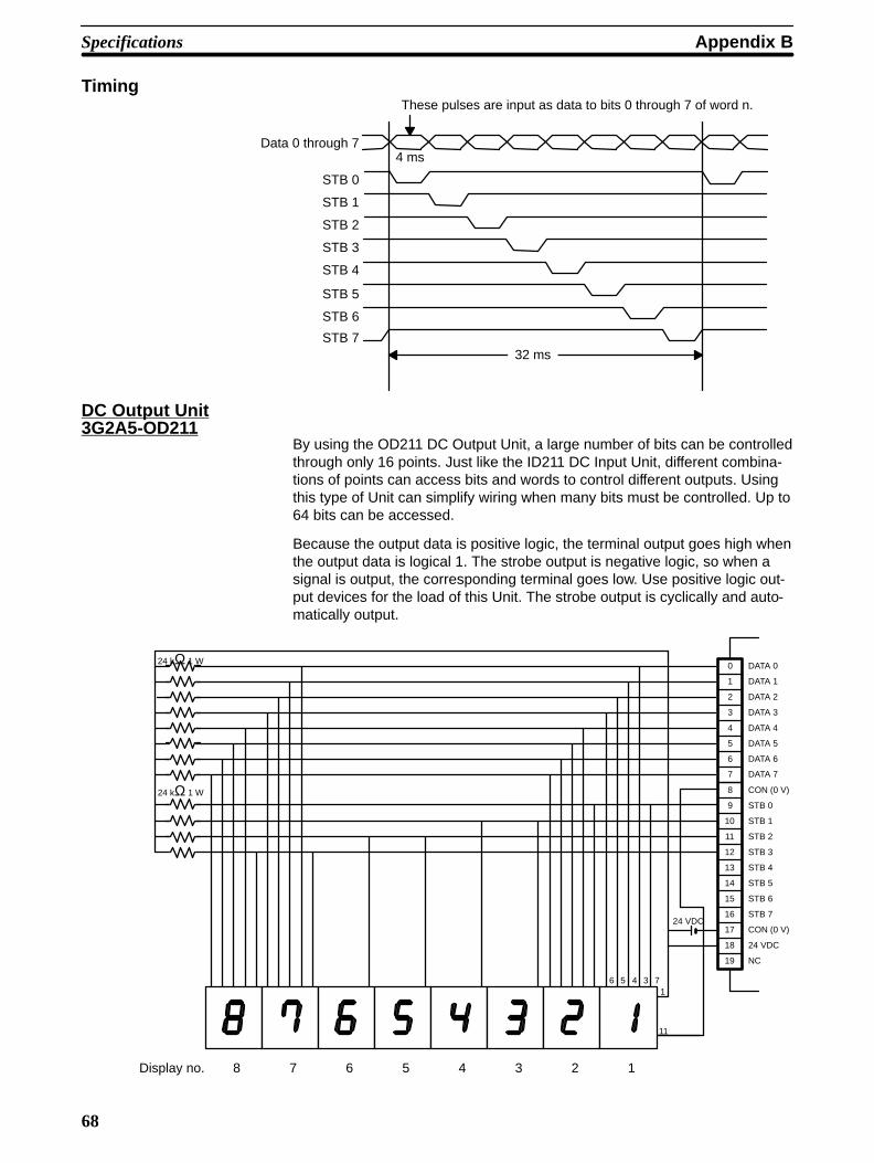
Appendix BSpecifications
68
TimingThese pulses are input as data to bits 0 through 7 of word n.
32 ms
4 msData 0 through 7
STB 0
STB 1
STB 2
STB 3
STB 4
STB 5
STB 6
STB 7
DC Output Unit3G2A5-OD211
By using the OD211 DC Output Unit, a large number of bits can be controlledthrough only 16 points. Just like the ID211 DC Input Unit, different combina-tions of points can access bits and words to control different outputs. Usingthis type of Unit can simplify wiring when many bits must be controlled. Up to64 bits can be accessed.
Because the output data is positive logic, the terminal output goes high whenthe output data is logical 1. The strobe output is negative logic, so when asignal is output, the corresponding terminal goes low. Use positive logic out-put devices for the load of this Unit. The strobe output is cyclically and auto-matically output.
0
1
2
3
4
5
6
7
8
9
10
11
12
13
14
15
16
17
18
19
24 VDC
6 5 4 31
11
7
Display no. 8 7 6 5 4 3 2 1
24 kΩ 1 W
24 kΩ 1 W
DATA 0
DATA 1
DATA 2
DATA 3
DATA 4
DATA 5
DATA 6
DATA 7
CON (0 V)
STB 0
STB 1
STB 2
STB 3
STB 4
STB 5
STB 6
STB 7
CON (0 V)
24 VDC
NC
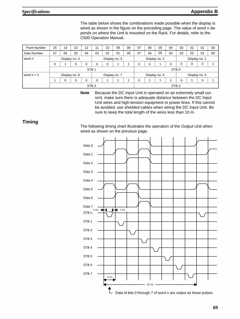
Specifications Appendix B
69
The table below shows the combinations made possible when the display iswired as shown in the figure on the preceding page. The value of word n de-pends on where the Unit is mounted on the Rack. For details, refer to theC500 Operation Manual.
Point Number 15 14 13 12 11 10 09 08 07 06 05 04 03 02 01 00
Data Number 07 06 05 04 03 02 01 00 07 06 05 04 03 02 01 00
word n Display no. 4 Display no. 3 Display no. 2 Display no. 1
0 1 0 0 0 0 1 1 0 0 1 0 0 0 0 1
STB 1 STB 0
word n + 1 Display no. 8 Display no. 7 Display no. 6 Display no. 5
1 0 0 0 0 1 1 1 0 1 1 0 0 1 0 1
STB 3 STB 2
Note Because the DC Input Unit is operated on an extremely small cur-rent, make sure there is adequate distance between the DC InputUnit wires and high-tension equipment or power lines. If this cannotbe avoided, use shielded cables when wiring the DC Input Unit. Besure to keep the total length of the wires less than 10 m.
TimingThe following timing chart illustrates the operation of the Output Unit whenwired as shown on the previous page.
Data 0
Data 1
Data 2
Data 3
Data 4
Data 5
Data 6
Data 7
STB 0
STB 1
STB 2
STB 3
STB 4
STB 5
STB 6
STB 7
1 ms2 ms
1 ms
4 ms
32 ms
Data of bits 0 through 7 of word n are output as these pulses.

Appendix BSpecifications
70
TTL Input Units3G2A5-ID501CN
Input Voltage 5 VDC ±10%
Input Impedance 1 kΩInput Current 3.5 mA typical (at 24 VDC)
ON Voltage 3 VDC min.
OFF Voltage 1 VDC max.
ON ResponseTime
1.5 ms max.
OFF ResponseTime
1.5 ms max.
No. of Points 32 (8 points/common, 4 circuits)
Internal CurrentConsumption
200 mA 5 VDC max.
Weight 450 grams max.
CircuitConfiguration
Inter-nalCircuit
COM
COM
IN 00to
IN 07
IN 15
1 kΩ
3.3 kΩ
1 kΩ
3.3 kΩ
IN 08to
COM
COM
IN 00
to
IN 07
IN 15
IN 08to
I
IIII
TerminalConnections
+
0
1
2
3
4
5
6
7
123456789101112
COMNC
8
9
10
11
12
13
14
15
123456789101112
COM
A B
+
+
+
5 VDC5 VDC
NCNC
NC
NCNC
1 kΩ
3.3kΩ
IN
COM
Use a synchronous TTL buffer.
(TTL/LS-TTL/CMOS buffer)
Dimensions E-shape, with no 4-terminal block

Specifications Appendix B
71
Triac Output Units
3G2A5-OA121 3G2A5-OA222
Max. switching Capacity
1 A 132 VAC, 50/60 Hz (4 A/common, 5 A/Unit) 1 A 250 VAC, 50/60 Hz (4 A/common, 5 A/Unit)
Min. switchingCapacity
10 mA (resistive load)40 mA (inductive load) 10 VAC
10 mA (resistive load)40 mA (inductive load) 10 VAC
Leakage Current 3 mA (100 VAC) max. 3 mA (100 VAC) max., 6 mA (200 VAC) max.
Residual Voltage 1.2 V max. 1.2 V max.
ON Response Time 1 ms max. 1 ms max.
OFF Response Time 1/2 of load frequency max. 1/2 of load frequency max.
No. of Points 16 (8 points/common, 2 circuits) 16 (8 points/common, 2 circuits)
Internal Current Consumption
300 mA 5 VDC max. 300 mA 5 VDC max.
Fuse Capacity 5 A 250 V (two fuses) 5 A 250 V (two fuses)
Weight 500 grams max. 500 grams max.
CircuitConfiguration
Inter-nalCircuit
OUT 00
OUT 07COM
OUT 08
OUT 15
to
to
COM
Fuse/fuse blowoutdetection circuit
22
Ω
0.022 µF
Fuse/fuse blowoutdetection circuit
22
Ω
0.022 µF
OUT 06
OUT 14
The fuse used in this diagram is 5 A 250 V6.35 dia. x 32.
Inter-nalCircuit
OUT 00
OUT 07COM
OUT 08
OUT 15
to
to
COM
Fuse/fuse blowoutdetection circuit
22
Ω
0.022 µF
Fuse/fuse blowoutdetection circuit
22
Ω
0.022 µF
OUT 06
OUT 14
The fuse used in this diagram is 5 A 250 V6.35 dia. x 32.
TerminalConnections
L
L
L
L
L
L
L
L
L
L
L
L
L
L
L
L
2345
COM
0
1
2
3
4
5
6
7
8
9
10
11
12
13
14
15 161718
01
6789101112131415
COM
~
~
19NC
NC
132 VAC max.
132 VAC max.
L
L
L
L
L
L
L
L
L
L
L
L
L
L
L
L
2345
COM
0
1
2
3
4
5
6
7
8
9
10
11
12
13
14
15 161718
01
6789101112131415
COM
~
~
19NC
NC
250 VAC max.
250 VAC max.
Dimensions A-shape A-shape
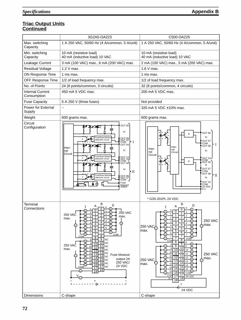
Appendix BSpecifications
72
Triac Output UnitsContinued
3G2A5-OA223 C500-OA225
Max. switching Capacity
1 A 250 VAC, 50/60 Hz (4 A/common, 5 A/unit) 1 A 250 VAC, 50/60 Hz (4 A/common, 5 A/unit)
Min. switchingCapacity
10 mA (resistive load)40 mA (inductive load) 10 VAC
10 mA (resistive load)40 mA (inductive load) 10 VAC
Leakage Current 3 mA (100 VAC) max., 6 mA (200 VAC) max. 2 mA (100 VAC) max., 5 mA (200 VAC) max.
Residual Voltage 1.2 V max. 1.6 V max.
ON Response Time 1 ms max. 1 ms max.
OFF Response Time 1/2 of load frequency max. 1/2 of load frequency max.
No. of Points 24 (8 points/common, 3 circuits) 32 (8 points/common, 4 circuits)
Internal Current Consumption
450 mA 5 VDC max. 200 mA 5 VDC max.
Fuse Capacity 5 A 250 V (three fuses) Not provided
Power for ExternalSupply
– 320 mA 5 VDC ±10% max.
Weight 600 grams max. 600 grams max.
CircuitConfiguration
Inter-nalCircuit
OUT 00
OUT 07COM
to
OUT 06
OUT 15COM
Fuse/fuse blowoutdetection circuit
OUT 14Fuse/fuse blowoutdetection circuit
Fuse/fuse blowoutdetection circuit
x
OUT 04
to
OUT 00
OUT 07COM
to
OUT 06
Fuseblowoutoutput
I
II
Inter-nalCircuit
Inter-nalCircuit
OUT 00
OUT 07COM
to
OUT 15COM
*
I
II
*
OUT 08
OUT 00
OUT 07COM
to
OUT 08
OUT 15
to
COM24 VDC0 V
to
* G3S-201PL 24 VDC
TerminalConnections
~
L
~+
2345
COM
01234567
89
101112131415 16
1718
01
6789101112131415
COM
01234567
161718
0123456789101112131415
COM
AB III
~~
NCNCNCNCNCNCNCNCNC
V
250 VACmax.
250 VACmax.
250 VACmax.
Fuse blowoutoutput 2A250 VAC/24 VDC
LLLL
LLLL
LLLLLL
LL
LLLL
LLLL
L
L
L
L
L
L
L
L
L
L
L
L
L
L
L
L
L
L
L
L
L
L
L
L
L
L
L
L
L
L
L
L
+
24 VDC
2345
COM
0
1
2
3
4
5
6
7
8
9
10
11
12
13
14
15 161718
01
6789101112131415
COM
COM
0
1
2
3
4
5
6
7
8
9
10
11
12
13
14
15161718
0123456789101112131415
COM
AB III
~
~
~
~
250 VACmax.
0 V
250 VACmax.
250 VACmax.
250 VACmax.
24 VDC
Dimensions C-shape C-shape
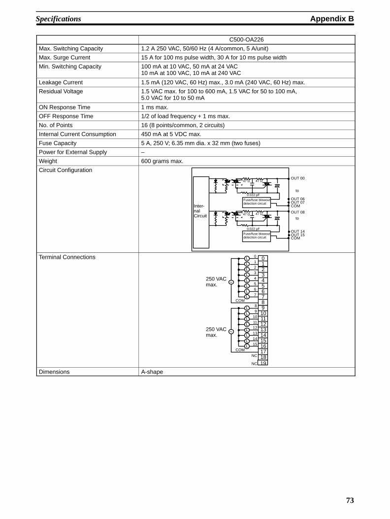
Specifications Appendix B
73
C500-OA226
Max. Switching Capacity 1.2 A 250 VAC, 50/60 Hz (4 A/common, 5 A/unit)
Max. Surge Current 15 A for 100 ms pulse width, 30 A for 10 ms pulse width
Min. Switching Capacity 100 mA at 10 VAC, 50 mA at 24 VAC10 mA at 100 VAC, 10 mA at 240 VAC
Leakage Current 1.5 mA (120 VAC, 60 Hz) max., 3.0 mA (240 VAC, 60 Hz) max.
Residual Voltage 1.5 VAC max. for 100 to 600 mA, 1.5 VAC for 50 to 100 mA,5.0 VAC for 10 to 50 mA
ON Response Time 1 ms max.
OFF Response Time 1/2 of load frequency + 1 ms max.
No. of Points 16 (8 points/common, 2 circuits)
Internal Current Consumption 450 mA at 5 VDC max.
Fuse Capacity 5 A, 250 V; 6.35 mm dia. x 32 mm (two fuses)
Power for External Supply –
Weight 600 grams max.
Circuit Configuration
Inter-nalCircuit
OUT 00
OUT 07COM
to
OUT 06
OUT 15COM
OUT 14
OUT 08
to
47 Ω
0.022 µF
47 Ω
Fuse/fuse blowoutdetection circuit
47 Ω 47 Ω
0.022 µF
Fuse/fuse blowoutdetection circuit
Terminal Connections
~
2345
COM
01234567
89
101112131415 16
1718
01
6789101112131415
COM
~250 VACmax.
250 VACmax.
LLLLLLLL
LLLL
LLLL
19
NC
NC
Dimensions A-shape
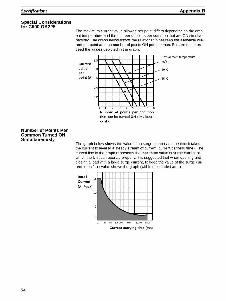
Appendix BSpecifications
74
Special Considerationsfor C500-OA225
The maximum current value allowed per point differs depending on the ambi-ent temperature and the number of points per common that are ON simulta-neously. The graph below shows the relationship between the allowable cur-rent per point and the number of points ON per common. Be sure not to ex-ceed the values depicted in the graph.
1.0
0.8
0.6
0.4
0.2
0 1 2 3 4 5 6 7 8
Currentvalueperpoint (A)
Number of points per commonthat can be turned ON simultane -ously.
25°C
40°C
55°C
Environment temperature
Number of Points PerCommon Turned ONSimultaneously
The graph below shows the value of an surge current and the time it takesthe current to level to a steady stream of current (current-carrying time). Thecurved line in the graph represents the maximum value of surge current atwhich the Unit can operate properly. It is suggested that when opening andclosing a load with a large surge current, to keep the value of the surge cur-rent to half the value shown the graph (within the shaded area).
0
10
5
15
10 30 50 100 200 500 1,000 5.000
InrushCurrent(A. Peak)
Current-carrying time (ms)
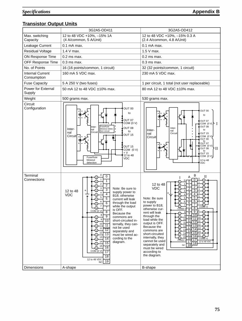
Specifications Appendix B
75
Transistor Output Units3G2A5-OD411 3G2A5-OD412
Max. switching Capacity
12 to 48 VDC +10%, –15% 1A (4 A/common, 5 A/Unit)
12 to 48 VDC +10%, –15% 0.3 A (2.4 A/common, 4.8 A/Unit)
Leakage Current 0.1 mA max. 0.1 mA max.
Residual Voltage 1.4 V max. 1.5 V max.
ON Response Time 0.2 ms max. 0.2 ms max.
OFF Response Time 0.3 ms max. 0.3 ms max.
No. of Points 16 (16 points/common, 1 circuit) 32 (32 points/common, 1 circuit)
Internal Current Consumption
160 mA 5 VDC max. 230 mA 5 VDC max.
Fuse Capacity 5 A 250 V (two fuses) 1 per circuit, 1 total (not user replaceable)
Power for ExternalSupply
50 mA 12 to 48 VDC ±10% max. 80 mA 12 to 48 VDC ±10% max.
Weight 500 grams max. 530 grams max.
CircuitConfiguration
Fuse/fuseblowout detec-tion circuit
Fuse/fuseblowoutdetection
Inter-nalCircuit
Inter-nalCircuit
OUT 00
OUT 07COM
OUT 15
OUT 15
(0 V)
to
to
COM (0 V)
12 to 48VDC
OUT 08
+ V
Inter-nalCircuit
Inter-nalCircuit
OUT 00
OUT 07COMOUT 08
OUT 15
(0 V)
to
to
12 to 48VDC
COM (0 V)OUT 00
OUT 07
COM (0 V)OUT 15
OUT 08COM (0 V)
to
I
II
to
TerminalConnections
L
L
L
L
L
L
L
L
L
L
L
L
L
L
L
L
15
COM (0 V)
0
1
2
3
4
5
6
7
8
9
10
11
12
13
14
15 161718
01234567891011121314
+
19
COM (0 V)
12 to 48 VDCNC
12 to 48VDC
Note: Be sure tosupply power toB18; otherwisecurrent will leakthrough the loadwhile the outputis OFF.Because thecommons areshort-circuited in-ternally, they can-not be usedseparately andmust be wired ac-cording to thediagram.
L
L
L
L
L
L
L
L
L
L
L
L
L
L
L
L
L
L
L
L
L
L
L
L
L
L
L
L
L
L
L
L
2345
0
12
3
4
5
6
7
8
9
10
11
12
13
14
15 161718
01
6789101112131415
COM(0 V)
0
12
3
4
5
6
7
8
9
1011
12
13
14
15161718
0123456789101112131415
A B III
+
COM(0 V)
COM(0 V)
COM(0 V)
12 to 48 VDC
12 to 48VDC
NC
Note: Be sureto supplypower to B18;otherwise cur-rent will leakthrough theload while theoutput is OFF.Because thecommons areshort-circuitedinternally, theycannot be usedseparately andmust be wiredaccording tothe diagram.
Dimensions A-shape B-shape
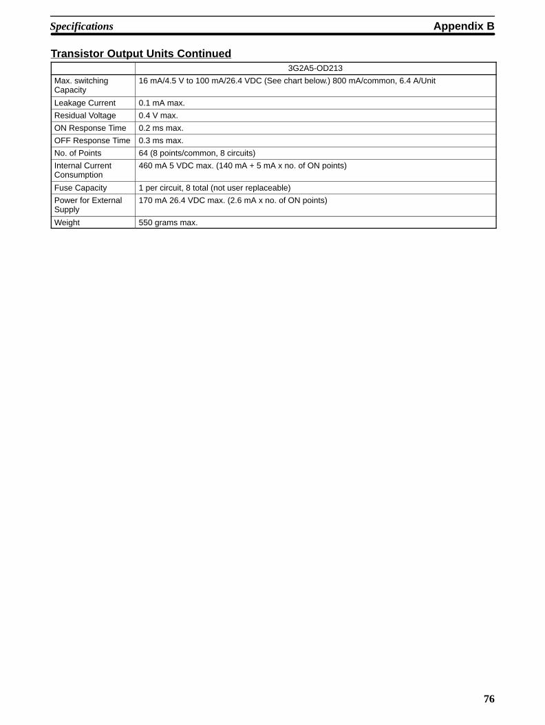
Specifications Appendix B
76
Transistor Output Units Continued3G2A5-OD213
Max. switching Capacity
16 mA/4.5 V to 100 mA/26.4 VDC (See chart below.) 800 mA/common, 6.4 A/Unit
Leakage Current 0.1 mA max.
Residual Voltage 0.4 V max.
ON Response Time 0.2 ms max.
OFF Response Time 0.3 ms max.
No. of Points 64 (8 points/common, 8 circuits)
Internal Current Consumption
460 mA 5 VDC max. (140 mA + 5 mA x no. of ON points)
Fuse Capacity 1 per circuit, 8 total (not user replaceable)
Power for ExternalSupply
170 mA 26.4 VDC max. (2.6 mA x no. of ON points)
Weight 550 grams max.

Appendix BSpecifications
77
3G2A5-OD213
Circuit Configuration
InternalCircuit
4.5 to26.4 VDC
OUT 00to
OUT 07
COM
OUT 08
OUT 15
COM
to
OUT 00to
OUT 07COM
OUT 08
OUT 15COM
to
13 k
10 k
13 k
10 k
I4.5 to26.4 VDC
4.5 to26.4 VDC
4.5 to26.4 VDC
IV
Fuse
Fuse
Units manufactured on or before October 31st, 1999(manufacturing numbers 31X9 or earlier*)
InternalCircuit
4.5 to26.4 VDC
OUT 00to
OUT 07
COM
OUT 08
OUT 15
COM
to
6.8 k
15 k
6.8 k
15 k
I4.5 to26.4 VDC
Fuse
Fuse
Units manufactured on or after November 1st, 1999(manufacturing numbers 01Y9 or later*)
OUT 00to
OUT 07COM
OUT 08
OUT 15COM
to
4.5 to26.4 VDC
4.5 to26.4 VDC
IV
*Manufacturing Numbers
Y9Year: Last digit of calendar year; e.g., 1999→9, 2000→0
Month: 1 to 9 (January to September), X (October), Y (November), Z (December)
Day: 01 to 31
0
50
100
0 10 20.4
16
4.5 26.4(V)
(mA)
Voltage for external supply
Max.switchingcapacity
Max. switching capacity

Specifications Appendix B
78
3G2A5-OD213
TerminalConnections
L
L
L
L
L
L
L
L
L
L
L
L
L
L
L
L
L
L
L
L
L
L
L
L
L
L
L
L
L
L
L
L
L
L
L
L
L
L
L
L
L
L
L
L
L
L
L
L
L
L
L
L
L
L
L
L
L
L
L
L
L
L
L
L
161718
131415
1920
161718
131415
1920
+
0
1
2
3
4
5
6
7
8
9
10
11
12
13
14
15
COM
+
A B123456789101112
123456789101112
COM
+
0
1
2
3
4
5
6
7
8
9
10
11
12
13
14
15
COM
+
COM
+
0
1
2
3
4
5
6
7
8
9
10
11
12
13
14
15
COM
+
AB
161718
123456789101112131415
1920
161718
123456789101112131415
1920
COM
+
0
1
2
3
4
5
6
7
8
9
10
11
12
13
14
15
COM
+
COM
III III IV
4.5 to 26.4 VDC
When wiring outputcircuits, be sure touse the correct polar-ity for the externalpower supplies. Wir-ing with incorrectpolarity may result inerroneous operationof the load.
Dimensions D-shape
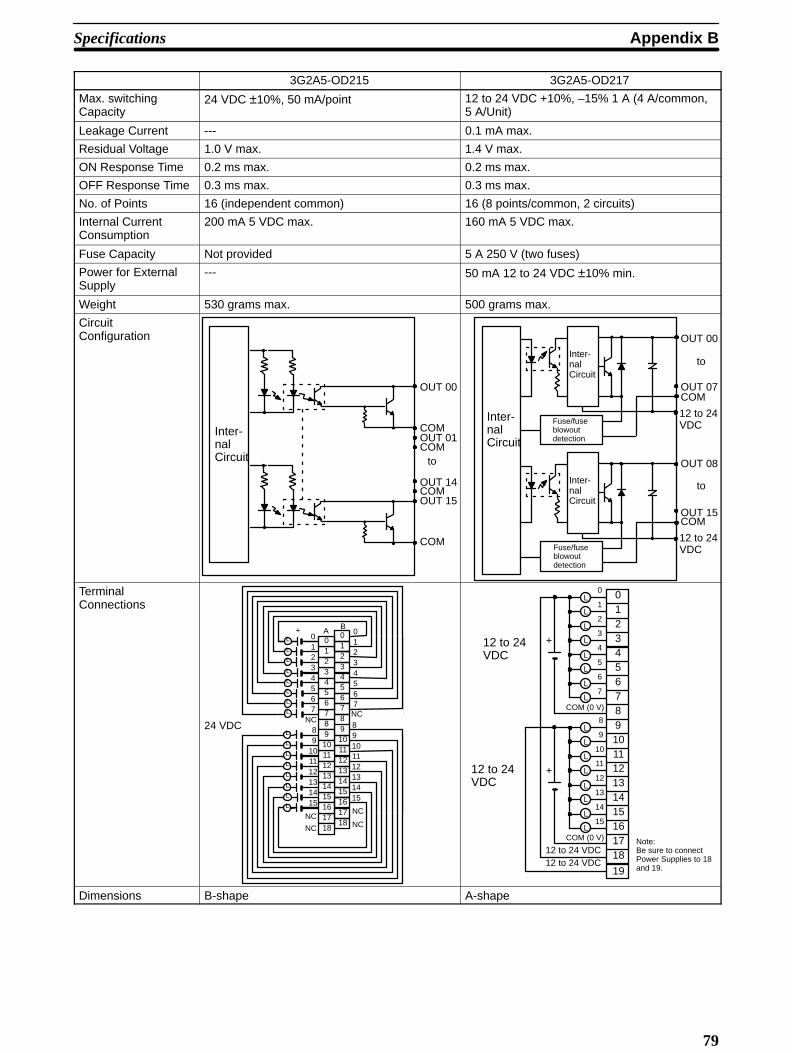
Appendix BSpecifications
79
3G2A5-OD215 3G2A5-OD217
Max. switching Capacity
24 VDC ±10%, 50 mA/point 12 to 24 VDC +10%, –15% 1 A (4 A/common,5 A/Unit)
Leakage Current --- 0.1 mA max.
Residual Voltage 1.0 V max. 1.4 V max.
ON Response Time 0.2 ms max. 0.2 ms max.
OFF Response Time 0.3 ms max. 0.3 ms max.
No. of Points 16 (independent common) 16 (8 points/common, 2 circuits)
Internal Current Consumption
200 mA 5 VDC max. 160 mA 5 VDC max.
Fuse Capacity Not provided 5 A 250 V (two fuses)
Power for ExternalSupply
--- 50 mA 12 to 24 VDC ±10% min.
Weight 530 grams max. 500 grams max.
CircuitConfiguration
Inter-nalCircuit
OUT 00
OUT 01COM
OUT 14
OUT 15
to
COM
COM
COM
Inter-nalCircuit
Inter-nalCircuit
OUT 00
OUT 07COM
OUT 08
OUT 15
to
to
COM
Fuse/fuseblowoutdetection
Inter-nalCircuit
Fuse/fuseblowoutdetection
12 to 24VDC
12 to 24VDC
TerminalConnections
L
L
L
L
L
L
L
L
L
L
L
L
L
L
L
L
89
101112131415
A B
2345
161718
6789101112131415
NC
NC
89101112131415
NC
NC
24 VDCNC
01234567
2345
1
678
1718
9101112131415
01
001234567
+
16 NC
L
L
L
L
L
L
L
L
L
L
L
L
L
L
L
L
15
COM (0 V)
0
1
2
3
4
5
6
7
8
9
10
11
12
13
14
15 161718
01234567891011121314
+
19
COM (0 V)
12 to 24VDC
+
12 to 24 VDC12 to 24 VDC
12 to 24VDC
Note:Be sure to connectPower Supplies to 18and 19.
Dimensions B-shape A-shape
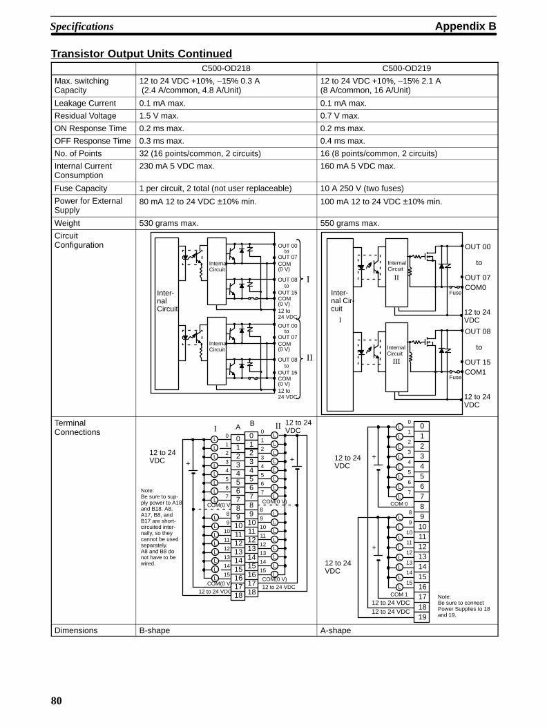
Specifications Appendix B
80
Transistor Output Units ContinuedC500-OD218 C500-OD219
Max. switching Capacity
12 to 24 VDC +10%, –15% 0.3 A (2.4 A/common, 4.8 A/Unit)
12 to 24 VDC +10%, –15% 2.1 A (8 A/common, 16 A/Unit)
Leakage Current 0.1 mA max. 0.1 mA max.
Residual Voltage 1.5 V max. 0.7 V max.
ON Response Time 0.2 ms max. 0.2 ms max.
OFF Response Time 0.3 ms max. 0.4 ms max.
No. of Points 32 (16 points/common, 2 circuits) 16 (8 points/common, 2 circuits)
Internal Current Consumption
230 mA 5 VDC max. 160 mA 5 VDC max.
Fuse Capacity 1 per circuit, 2 total (not user replaceable) 10 A 250 V (two fuses)
Power for ExternalSupply
80 mA 12 to 24 VDC ±10% min. 100 mA 12 to 24 VDC ±10% min.
Weight 530 grams max. 550 grams max.
CircuitConfiguration OUT 00
toOUT 07COM(0 V)
OUT 08
OUT 15
12 to24 VDC
to
COM(0 V)
OUT 00to
OUT 07COM(0 V)
OUT 08
OUT 15
12 to24 VDC
to
COM(0 V)
Inter-nalCircuit
InternalCircuit
InternalCircuit
I
II
Inter-nal Cir-cuit
InternalCircuit
OUT 00
OUT 07COM0
to
12 to 24VDC
Fuse
InternalCircuit
OUT 08
OUT 15COM1
to
12 to 24VDC
Fuse
I
II
III
TerminalConnections
L
L
L
L
L
L
L
L
L
L
L
L
L
L
L
L
L
L
L
L
L
L
L
L
L
L
L
L
L
L
L
L
2345
0
1
2
3
4
5
6
7
8
9
10
11
12
13
14
15 161718
01
6789101112131415
COM(0 V)
0
1
2
3
4
5
6
7
8
9
10
11
12
13
14
15161718
0123456789101112131415
A B III
+
COM(0 V)
COM(0 V)
COM(0 V)
12 to 24 VDC12 to 24 VDC
12 to 24VDC +
12 to 24VDC
Note:Be sure to sup-ply power to A18and B18. A8,A17, B8, andB17 are short-circuited inter-nally, so theycannot be usedseparately.A8 and B8 donot have to bewired.
L
L
L
L
L
L
L
L
L
L
L
L
L
L
L
L
15
COM 1
0
1
2
3
4
5
6
7
8
9
10
11
12
13
14
15161718
01234567891011121314
+
19
COM 0
12 to 24VDC
+
12 to 24 VDC12 to 24 VDC
12 to 24VDC
Note:Be sure to connectPower Supplies to 18and 19.
Dimensions B-shape A-shape
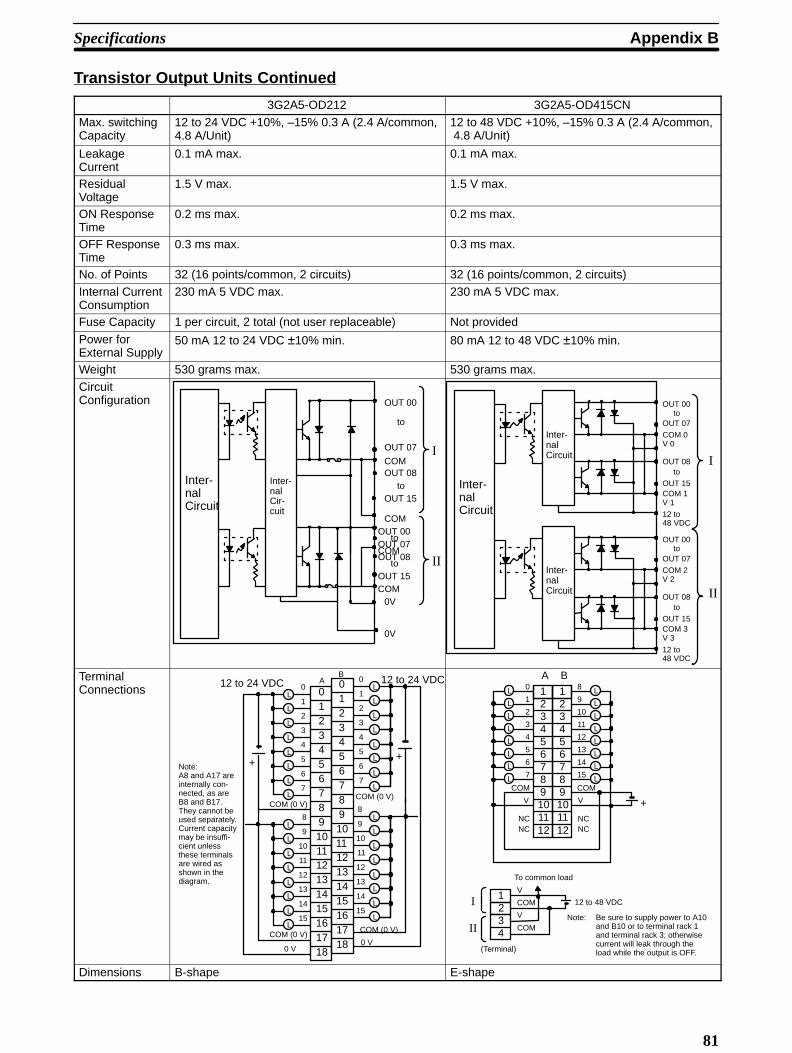
Appendix BSpecifications
81
Transistor Output Units Continued
3G2A5-OD212 3G2A5-OD415CN
Max. switching Capacity
12 to 24 VDC +10%, –15% 0.3 A (2.4 A/common,4.8 A/Unit)
12 to 48 VDC +10%, –15% 0.3 A (2.4 A/common, 4.8 A/Unit)
LeakageCurrent
0.1 mA max. 0.1 mA max.
ResidualVoltage
1.5 V max. 1.5 V max.
ON ResponseTime
0.2 ms max. 0.2 ms max.
OFF ResponseTime
0.3 ms max. 0.3 ms max.
No. of Points 32 (16 points/common, 2 circuits) 32 (16 points/common, 2 circuits)
Internal CurrentConsumption
230 mA 5 VDC max. 230 mA 5 VDC max.
Fuse Capacity 1 per circuit, 2 total (not user replaceable) Not provided
Power forExternal Supply
50 mA 12 to 24 VDC ±10% min. 80 mA 12 to 48 VDC ±10% min.
Weight 530 grams max. 530 grams max.
CircuitConfiguration
Inter-nalCircuit
OUT 00
OUT 07
OUT 08
OUT 15
to
to
OUT 08
OUT 15to
Inter-nalCir-cuit
I
II
COM
COM
COM
OUT 00OUT 07
to
COM0V
0V
Inter-nalCircuit
Inter-nalCircuit
Inter-nalCircuit
OUT 00to
OUT 07
COM 0V 0
OUT 08
OUT 15
12 to48 VDC
to
COM 1V 1
I
II
OUT 00to
OUT 07
COM 2V 2
OUT 08
OUT 15
12 to48 VDC
to
COM 3V 3
TerminalConnections L
L
L
L
L
L
L
L
L
L
L
L
L
L
L
L
15
COM (0 V)
0
1
2
3
4
5
6
7
8
9
10
11
12
13
14
15 161718
01234567891011121314
COM (0 V)
12 to 24 VDC L
L
L
L
L
L
L
L
L
L
L
L
L
L
L
L
15
COM (0 V)
0
1
2
3
4
5
6
7
8
9
10
11
12
13
14
15161718
01234567891011121314
COM (0 V)
++
12 to 24 VDC
0 V0 V
AB
Note:A8 and A17 areinternally con-nected, as areB8 and B17.They cannot beused separately.Current capacitymay be insuffi-cient unlessthese terminalsare wired asshown in thediagram.
L
L
L
L
L
L
L
L
L
L
L
L
L
L
L
L
0
1
2
3
4
5
6
7
8
9
10
11
12
13
14
15
123456789101112
B
123456789101112
A
COM COM
NCNC
NCNC
+V V
1234
COM
V
COM
V
I
IINote: Be sure to supply power to A10
and B10 or to terminal rack 1and terminal rack 3; otherwisecurrent will leak through theload while the output is OFF.
To common load
12 to 48 VDC
(Terminal)
Dimensions B-shape E-shape
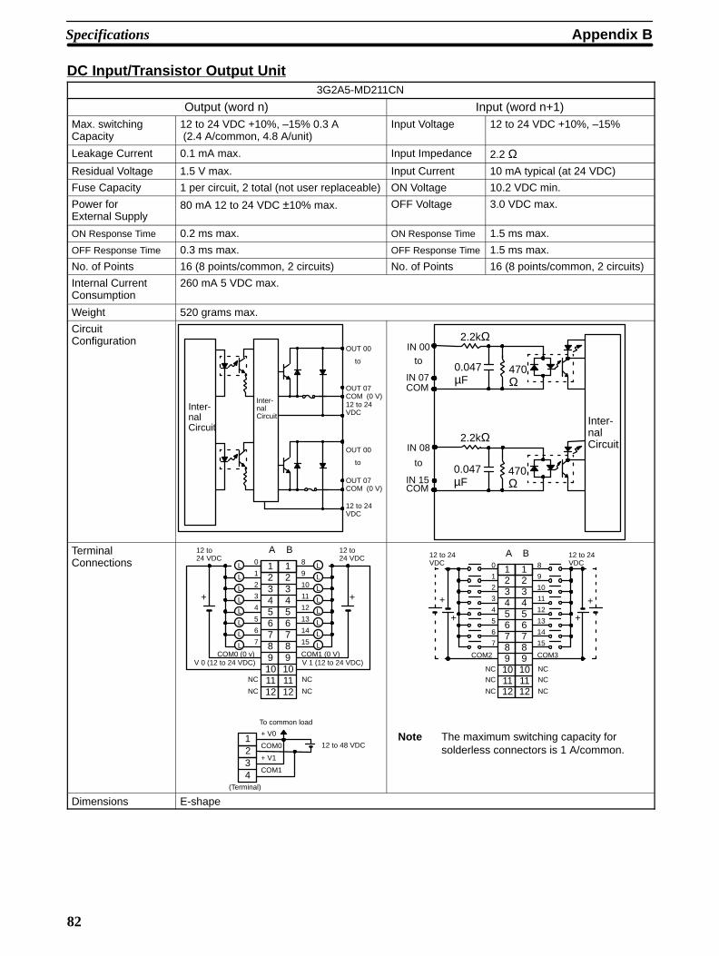
Specifications Appendix B
82
DC Input/Transistor Output Unit3G2A5-MD211CN
Output (word n) Input (word n+1)Max. switching Capacity
12 to 24 VDC +10%, –15% 0.3 A (2.4 A/common, 4.8 A/unit)
Input Voltage 12 to 24 VDC +10%, –15%
Leakage Current 0.1 mA max. Input Impedance 2.2 ΩResidual Voltage 1.5 V max. Input Current 10 mA typical (at 24 VDC)
Fuse Capacity 1 per circuit, 2 total (not user replaceable) ON Voltage 10.2 VDC min.
Power for External Supply
80 mA 12 to 24 VDC ±10% max. OFF Voltage 3.0 VDC max.
ON Response Time 0.2 ms max. ON Response Time 1.5 ms max.
OFF Response Time 0.3 ms max. OFF Response Time 1.5 ms max.
No. of Points 16 (8 points/common, 2 circuits) No. of Points 16 (8 points/common, 2 circuits)
Internal Current Consumption
260 mA 5 VDC max.
Weight 520 grams max.
CircuitConfiguration
Inter-nalCircuit
Inter-nalCircuit
OUT 00
OUT 07COM12 to 24VDC
(0 V)
to
OUT 00
OUT 07COM
12 to 24VDC
(0 V)
to
Inter-nalCircuit
COM
IN 00to
IN 07
2.2kΩ
2.2kΩ
COM
IN 08
to
IN 15
0.047µF
0.047µF
470Ω
470Ω
TerminalConnections L
L
L
L
L
L
L
L
L
L
L
L
L
L
L
L
0
1
2
3
4
5
6
7
8
9
10
11
12
13
14
15
123456789101112
B
+
123456789101112
+
A
COM0 (0 v) COM1 (0 V)
NC
NC
NC
NC
12 to 24 VDC
V 0 (12 to 24 VDC) V 1 (12 to 24 VDC)
12 to 24 VDC
1234
COM0
+ V0
COM1
+ V1
To common load
12 to 48 VDC
(Terminal)
+
0
1
2
3
4
5
6
7
8
9
10
11
12
13
14
15
123456789101112
B
+
123456789101112
+
A
COM2 COM3
NC
NC
NC
NC
+
NC NC
12 to 24VDC
12 to 24VDC
Note The maximum switching capacity forsolderless connectors is 1 A/common.
Dimensions E-shape

Appendix BSpecifications
83
TTL Output Units
C500-OD501CN
Max. switching Capacity
5 VDC ±10% 35 mA/point
Leakage Current 0.1 mA max.
Residual Voltage 0.4 V max.
ON Response Time 0.2 ms max.
OFF Response Time 0.3 ms max.
No. of Points 32 (8 points/common, 4 circuits)
Internal Current Consumption
250 mA 5 VDC max.
Fuse Capacity Not provided
Power for ExternalSupply
32 mA 5 VDC ±10% min.
Weight 450 grams max.
CircuitConfiguration
Inter-nalCircuit
5 VDC
OUT 00to
OUT 07
COM
OUT 08
OUT 15
5 VDC
COM
to
5 VDC
OUT 00to
OUT 07
COM
OUT 08
OUT 15
5 VDC
COM
to
10 kΩ
10kΩ
12 kΩ
10 kΩ
10kΩ
12 kΩ
I
IV
TerminalConnections L
L
L
L
L
L
L
L
L
L
L
L
L
L
L
L
0
1
2
3
4
5
6
7
8
9
10
11
12
13
14
15
123456789101112
B
+
123456789101112
+
A
COM
5 VDC
COM
5 VDC
NC
NC
NC
NC
5 VDC 5 VDC
+10 kΩ
10kΩ
TTL
Because the output data is negative logic, the termi-nal output goes low when output data is logical 1.
Dimensions E-shape

Specifications Appendix B
84
Dummy I/O Unit
3G2A5-DUM01
Selection Function Unit designation: input/output Point designation: 16/32/64points
Internal Current Consumption
35 mA 5 VDC max.
Power for ExternalSupply
30 mA 24 VDC ±10% min.
Weight 450 grams max.
TerminalConnections
+
2345
161718
01
6789101112131415
24 VDC19
Short-circuit:Open:
inputoutput
Pointdesignation16 points32 points
64 points
TerminalconnectionOpen 3,4, and 5Short 3 and 4.Open 5.
Short 4 and 5.Open 3.
Dimensions A-shape
Note Power is supplied to the Dummy I/O Unit from the 24 VDC outputterminal of the Power Supply, which is mounted on the same Rackas the Dummy I/O Unit. Be sure to supply power to the Dummy I/OUnit before supplying power to the CPU. If power is supplied to theDummy I/O Unit after power is supplied to the CPU, the Dummy I/OUnit is assumed to have only 16 I/O points, and may result in an I/OVerification Error or an I/O Setting Error.
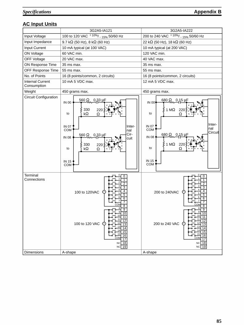
Appendix BSpecifications
85
AC Input Units3G2A5-IA121 3G2A5-IA222
Input Voltage 100 to 120 VAC 10%/15% 50/60 Hz 200 to 240 VAC 10%/15% 50/60 Hz
Input Impedance 9.7 kΩ (50 Hz), 8 kΩ (60 Hz) 22 kΩ (50 Hz), 18 kΩ (60 Hz)
Input Current 10 mA typical (at 100 VAC) 10 mA typical (at 200 VAC)
ON Voltage 60 VAC min. 120 VAC min.
OFF Voltage 20 VAC max. 40 VAC max.
ON Response Time 35 ms max. 35 ms max.
OFF Response Time 55 ms max. 55 ms max.
No. of Points 16 (8 points/common, 2 circuits) 16 (8 points/common, 2 circuits)
Internal CurrentConsumption
10 mA 5 VDC max. 12 mA 5 VDC max.
Weight 450 grams max. 450 grams max.
Circuit Configuration
Inter-nalCir-cuit
COM
IN 00
to
560 Ω
IN 07
0.33 µF
220Ω
330kΩ
COM
IN 08
to
560 Ω
IN 15
0.33 µF
220Ω
330kΩ
COM
IN 00
to
680 Ω
IN 07
0.15 µF
220Ω
1 MΩ
COM
IN 08
to
680 Ω
IN 15
0.15 µF
220Ω
1 MΩ
Inter-nalCircuit
TerminalConnections
~
~
COM
NC
0
1
2
3
4
5
6
7
8
9
10
11
12
13
14
15 161718
0123456789101112131415
COM
100 to 120VAC
100 to 120 VAC
19NC
~
~
COM
NC
0
1
2
3
4
5
6
7
8
9
10
11
12
13
14
15 161718
0123456789101112131415
COM
200 to 240VAC
200 to 240 VAC
19NC
Dimensions A-shape A-shape
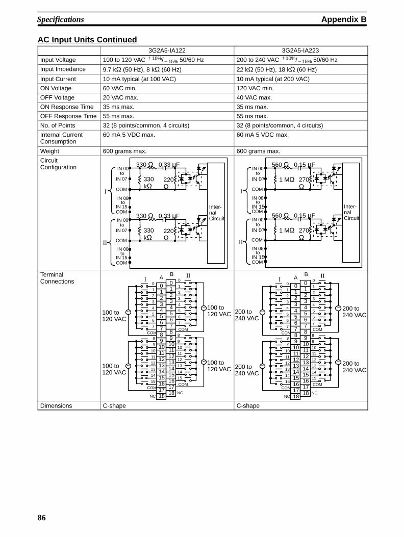
Specifications Appendix B
86
AC Input Units Continued3G2A5-IA122 3G2A5-IA223
Input Voltage 100 to 120 VAC 10%/15% 50/60 Hz 200 to 240 VAC 10%/15% 50/60 Hz
Input Impedance 9.7 kΩ (50 Hz), 8 kΩ (60 Hz) 22 kΩ (50 Hz), 18 kΩ (60 Hz)
Input Current 10 mA typical (at 100 VAC) 10 mA typical (at 200 VAC)
ON Voltage 60 VAC min. 120 VAC min.
OFF Voltage 20 VAC max. 40 VAC max.
ON Response Time 35 ms max. 35 ms max.
OFF Response Time 55 ms max. 55 ms max.
No. of Points 32 (8 points/common, 4 circuits) 32 (8 points/common, 4 circuits)
Internal CurrentConsumption
60 mA 5 VDC max. 60 mA 5 VDC max.
Weight 600 grams max. 600 grams max.
CircuitConfiguration
COM
COM
IN 00to
IN 07
IN 15
IN 08to
COM
COM
IN 00to
IN 07
IN 15
IN 08to
Inter-nalCircuit
330 Ω 0.33 µF
220Ω
330kΩ
330 Ω 0.33 µF
220Ω
330kΩ
I
II
COM
COM
IN 00to
IN 07
IN 15
IN 08to
COM
COM
IN 00to
IN 07
IN 15
IN 08to
Inter-nalCircuit
560 Ω 0.15 µF
270Ω
1 MΩ
560 Ω 0.15 µF
270Ω
1 MΩ
I
II
TerminalConnections
~
161718
12131415
~
~
~
COM
NC
0
1
2
3
4
5
6
7
8
9
10
11
12
13
14
15
01234567891011
COM
100 to120 VAC
100 to120 VAC
COM
NC
0
1
2
3
4
5
6
7
8
9
10
11
12
13
14
15161718
0123456789101112131415
COM
AB
III
100 to120 VAC
100 to120 VAC
~
161718
12131415
~
~
~
COM
NC
0
1
2
3
4
5
6
7
8
9
10
11
12
13
14
15
01234567891011
COM
200 to240 VAC
200 to240 VAC
COM
NC
0
1
2
3
4
5
6
7
8
9
10
11
12
13
14
15161718
0123456789101112131415
COM
AB
III
200 to240 VAC
200 to240 VAC
Dimensions C-shape C-shape
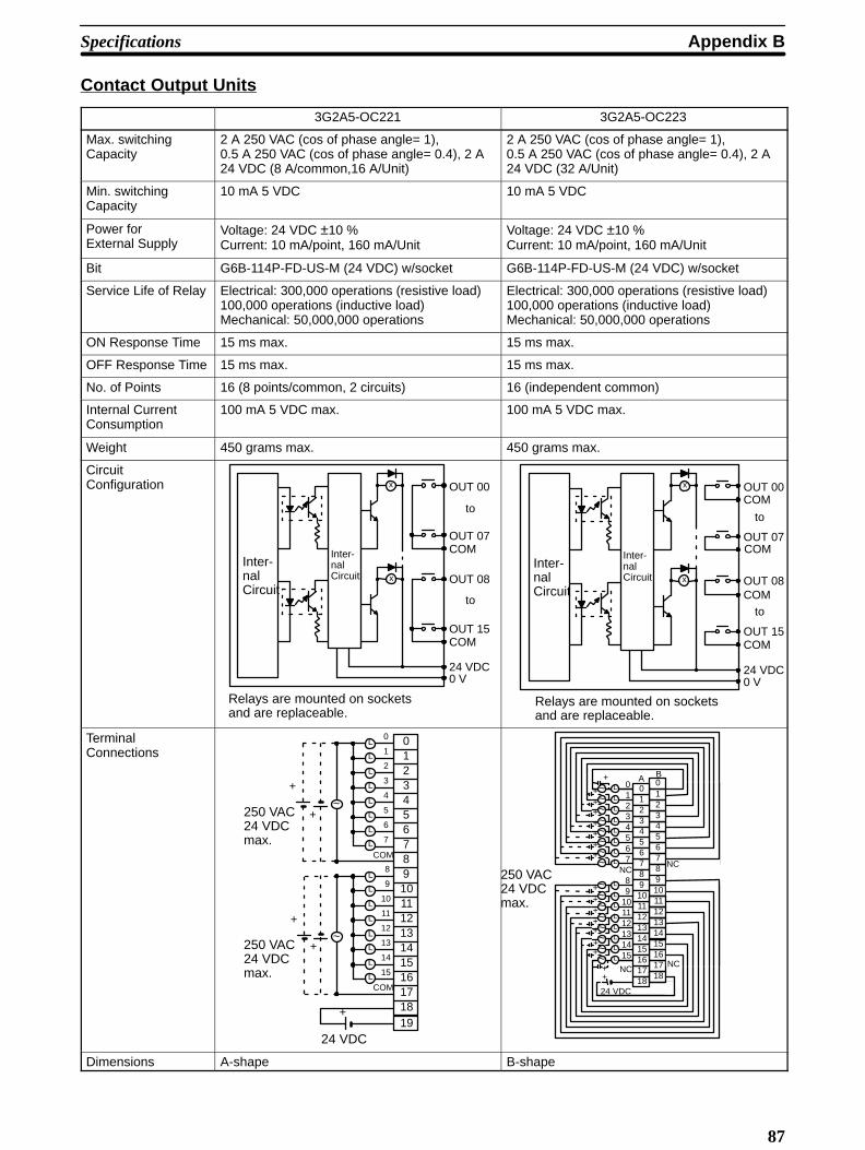
Appendix BSpecifications
87
Contact Output Units
3G2A5-OC221 3G2A5-OC223
Max. switching Capacity
2 A 250 VAC (cos of phase angle= 1), 0.5 A 250 VAC (cos of phase angle= 0.4), 2 A24 VDC (8 A/common,16 A/Unit)
2 A 250 VAC (cos of phase angle= 1), 0.5 A 250 VAC (cos of phase angle= 0.4), 2 A24 VDC (32 A/Unit)
Min. switchingCapacity
10 mA 5 VDC 10 mA 5 VDC
Power forExternal Supply
Voltage: 24 VDC ±10 %Current: 10 mA/point, 160 mA/Unit
Voltage: 24 VDC ±10 %Current: 10 mA/point, 160 mA/Unit
Bit G6B-114P-FD-US-M (24 VDC) w/socket G6B-114P-FD-US-M (24 VDC) w/socket
Service Life of Relay Electrical: 300,000 operations (resistive load)100,000 operations (inductive load)Mechanical: 50,000,000 operations
Electrical: 300,000 operations (resistive load)100,000 operations (inductive load)Mechanical: 50,000,000 operations
ON Response Time 15 ms max. 15 ms max.
OFF Response Time 15 ms max. 15 ms max.
No. of Points 16 (8 points/common, 2 circuits) 16 (independent common)
Internal Current Consumption
100 mA 5 VDC max. 100 mA 5 VDC max.
Weight 450 grams max. 450 grams max.
CircuitConfiguration x
x
Inter-nalCircuit
Inter-nalCircuit
OUT 00
OUT 07COM
OUT 08
OUT 15
0 V24 VDC
to
to
COM
Relays are mounted on socketsand are replaceable.
x
x
Inter-nalCircuit
Inter-nalCircuit
OUT 00
OUT 07
COM
OUT 08
OUT 15
0 V24 VDC
to
to
COM
COM
COM
Relays are mounted on socketsand are replaceable.
TerminalConnections
~
~
L
L
L
L
L
L
L
L
L
L
L
L
L
L
L
L
15
COM
+
+
COM
0
1
2
3
4
5
6
7
8
9
10
11
12
13
14
15 161718
01234567891011121314
+
+
19+
250 VAC24 VDCmax.
250 VAC24 VDCmax.
24 VDC
L
L
LLLLL
~~~~~~~
L
L
L
LLLL
~~~~~~~
L~
L
A B
2345
1617
01
678910
12131415
NC
2345
1
6789101112131415
01234567
89
101112131415
NC
NC
++
++
+
++
+
++
++
+
++
+ 1718
18+
24 VDC
0
~ 16 NC
250 VAC24 VDCmax. 11
Dimensions A-shape B-shape
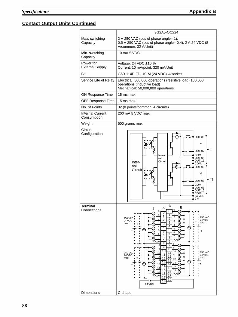
Specifications Appendix B
88
Contact Output Units Continued
3G2A5-OC224
Max. switching Capacity
2 A 250 VAC (cos of phase angle= 1), 0.5 A 250 VAC (cos of phase angle= 0.4), 2 A 24 VDC (8A/common, 32 A/Unit)
Min. switchingCapacity
10 mA 5 VDC
Power forExternal Supply
Voltage: 24 VDC ±10 %Current: 10 mA/point, 320 mA/Unit
Bit G6B-114P-FD-US-M (24 VDC) w/socket
Service Life of Relay Electrical: 300,000 operations (resistive load) 100,000operations (inductive load)Mechanical: 50,000,000 operations
ON Response Time 15 ms max.
OFF Response Time 15 ms max.
No. of Points 32 (8 points/common, 4 circuits)
Internal Current Consumption
200 mA 5 VDC max.
Weight 600 grams max.
CircuitConfiguration
x
x
Inter-nalCircuit
Inter-nalCircuit
OUT 00
OUT 07COMOUT 08OUT 15
0 V24 VDC
to
COMOUT 00
OUT 07COMOUT 08OUT 15
to
COM
I
II
TerminalConnections
L
L
L
L
L
L
L
L
L
L
L
L
L
L
L
L
L
L
L
L
L
L
L
L
L
L
L
L
L
L
L
L
+
24 VDC
2345
COM
0
1
2
3
4
5
6
7
8
9
10
11
12
13
14
15161718
01
6789101112131415
COM
COM
0
1
2
3
4
5
6
7
8
9
10
11
12
13
14
15161718
0123456789101112131415
COM
AB III
~
+
~
+
~
~
+
+
+ +
250 VAC24 VDCmax.
250 VAC24 VDCmax.
250 VAC24 VDCmax.
250 VAC24 VDCmax.
++
Dimensions C-shape
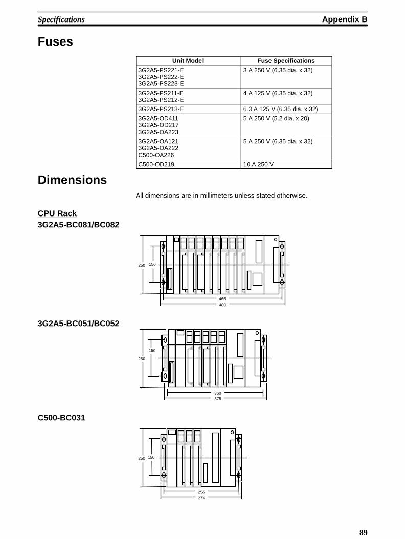
Appendix BSpecifications
89
FusesUnit Model Fuse Specifications
3G2A5-PS221-E3G2A5-PS222-E3G2A5-PS223-E
3 A 250 V (6.35 dia. x 32)
3G2A5-PS211-E3G2A5-PS212-E
4 A 125 V (6.35 dia. x 32)
3G2A5-PS213-E 6.3 A 125 V (6.35 dia. x 32)
3G2A5-OD4113G2A5-OD2173G2A5-OA223
5 A 250 V (5.2 dia. x 20)
3G2A5-OA1213G2A5-OA222C500-OA226
5 A 250 V (6.35 dia. x 32)
C500-OD219 10 A 250 V
DimensionsAll dimensions are in millimeters unless stated otherwise.
CPU Rack3G2A5-BC081/BC082
480465
150250
3G2A5-BC051/BC052
375360
150
250
C500-BC031
255276
150250
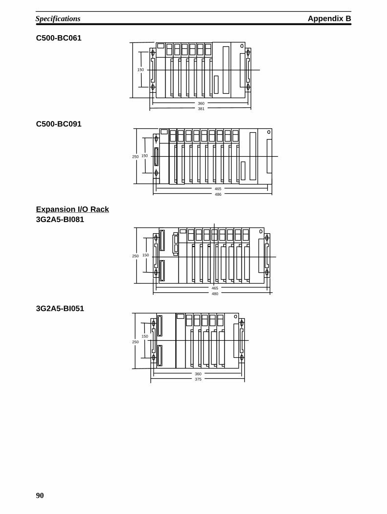
Specifications Appendix B
90
C500-BC061
381360
150
C500-BC091
486465
150250
Expansion I/O Rack3G2A5-BI081
480465
150250
3G2A5-BI051
375360
250
150
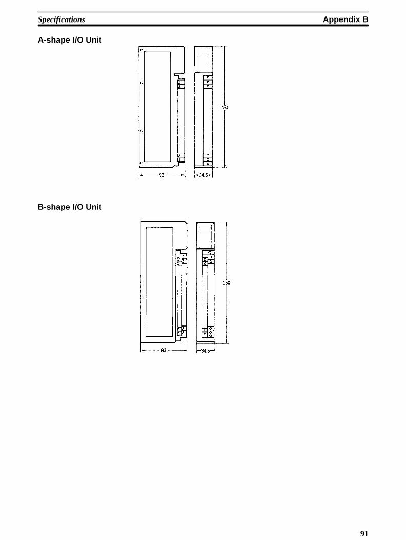
Appendix BSpecifications
91
A-shape I/O Unit
B-shape I/O Unit

Specifications Appendix B
92
C-shape I/O Unit
D-shape I/O Unit
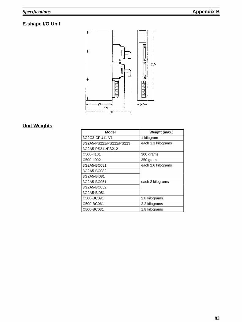
Appendix BSpecifications
93
E-shape I/O Unit
Unit WeightsModel Weight (max.)
3G2C3-CPU11-V1 1 kilogram
3G2A5-PS221/PS222/PS223 each 1.1 kilograms
3G2A5-PS211/PS212
g
C500-II101 300 grams
C500-II002 350 grams
3G2A5-BC081 each 2.6 kilograms
3G2A5-BC082
g
3G2A5-BI081
3G2A5-BC051 each 2 kilograms
3G2A5-BC052
g
3G2A5-BI051
C500-BC091 2.8 kilograms
C500-BC061 2.2 kilograms
C500-BC031 1.8 kilograms
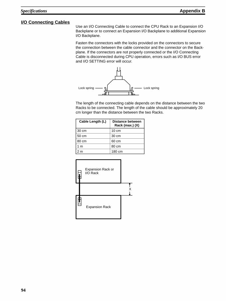
Specifications Appendix B
94
I/O Connecting CablesUse an I/O Connecting Cable to connect the CPU Rack to an Expansion I/OBackplane or to connect an Expansion I/O Backplane to additional ExpansionI/O Backplane.
Fasten the connectors with the locks provided on the connectors to securethe connection between the cable connector and the connector on the Back-plane. If the connectors are not properly connected or the I/O ConnectingCable is disconnected during CPU operation, errors such as I/O BUS errorand I/O SETTING error will occur.
Lock springLock spring
The length of the connecting cable depends on the distance between the twoRacks to be connected. The length of the cable should be approximately 20cm longer than the distance between the two Racks.
Cable Length (L) Distance betweenRack (max.) (X)
30 cm 10 cm
50 cm 30 cm
80 cm 60 cm
1 m 80 cm
2 m 180 cm
Expansion Rack orI/O Rack
Expansion Rack
X

Appendix BSpecifications
95
The figures below show the dimensions of the cable and the height of theconnector when the cable is connected to the Backplane.
L
Model Cable Length (L)
C500-CN312N 30 cm
C500-CN512N 50 cm
C500-CN812N 80 cm
C500-CN122N 1 m
C500-CN222N 2 m
The length of an individual connecting cable can not be extended more than2 m. Select each I/O cable and organize each device so the cable length iswithin 2 m.
Note Do not run the I/O connecting cable in the same duct with powerlines or other I/O lines.
ÇÇÇÇÇÇÇÇÇÇÇ
100 mm
Approx. 130 mm

97
C Standard Models
CPU Backplane
Name Remarks ModelBackplane 9 I/O slots* 5 Link slots C500-BC091
8 I/O slots 3 Link slots 3G2A5-BC081
5 Link slots 3G2A5-BC082
6 I/O slots 5 Link slots C500-BC061
5 I/O slots 3 Link slots 3G2A5-BC051
5 Link slots 3G2A5-BC052
3 I/O slots 3 Link slots C500-BC031
CPU – 3G2C3-CPU11-EV1
RAM Pack 16K words 3G2A5-MR431
24K words 3G2A5-MR831
ROM Pack 24K words max. 3G2A5-MP831
EPROM Chip 2764 250 ns Writing voltage21 V
ROM-H
27128 250 ns
g g21 V ROM-I
2764 200 ns Writing voltage12 5 V
ROM-HB-B
27128 200 ns
g g12.5 V ROM-IB-B
CPU Power Supply 100 to 120/200 to 240 VAC( l bl )
Output: 7 A 5 VDC 3G2A5-PS221-Ey(selectable) Output: 12 A 5 VDC 3G2A5-PS223-E
24 VDC Output: 7 A 5 VDC 3G2A5-PS211-E
Output: 9 A 5 VDC 3G2A5-PS213-E
Expansion I/O PowerSupply
100 to 120/200 to 240 VAC(selectable)
Output: 7 A 5 VDC 3G2A5-PS222-Ey
24 VDC Output: 7 A 5 VDC 3G2A5-PS212-E
I/O Control Unit Required to connect Expansion I/O Racks 3G2A5-II101
*The rightmost solt is only for Link Units.
Expansion I/O BackplaneName Remarks Model
Expansion I/O Backplane 8 slots 3G2A5-BI081
5 slots 3G2A5-BI051
Power Supply 100 to 120/200 to 240 VAC(selectable)
Output: 7 A 5 VDC 3G2A5-PS222-E
24 VDC Output: 7 A 5 VDC 3G2A5-PS212-E
I/O Interface Unit – 3G2A5-II002
I/O Connecting Cable 30 cm C500-CN312Ng
50 cm C500-CN512N
80 cm C500-CN812N
1 m C500-CN122N
2 m C500-CN222N
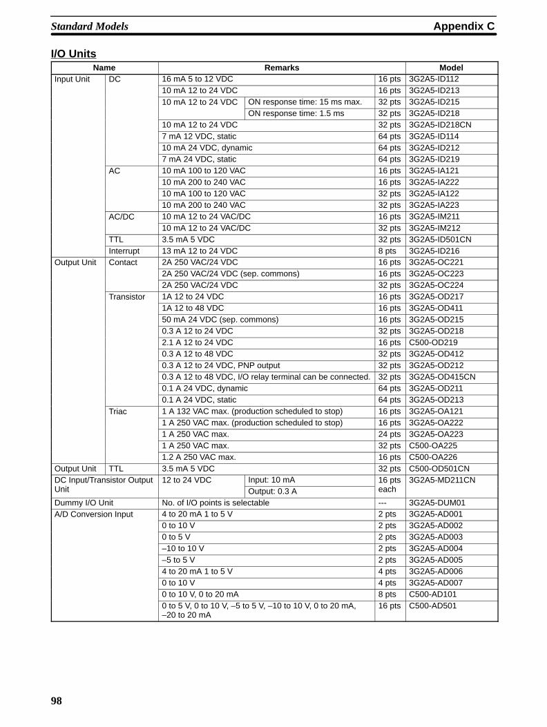
Appendix CStandard Models
98
I/O UnitsName Remarks Model
Input Unit DC 16 mA 5 to 12 VDC 16 pts 3G2A5-ID11210 mA 12 to 24 VDC 16 pts 3G2A5-ID21310 mA 12 to 24 VDC ON response time: 15 ms max. 32 pts 3G2A5-ID215
ON response time: 1.5 ms 32 pts 3G2A5-ID21810 mA 12 to 24 VDC 32 pts 3G2A5-ID218CN7 mA 12 VDC, static 64 pts 3G2A5-ID11410 mA 24 VDC, dynamic 64 pts 3G2A5-ID2127 mA 24 VDC, static 64 pts 3G2A5-ID219
AC 10 mA 100 to 120 VAC 16 pts 3G2A5-IA12110 mA 200 to 240 VAC 16 pts 3G2A5-IA22210 mA 100 to 120 VAC 32 pts 3G2A5-IA12210 mA 200 to 240 VAC 32 pts 3G2A5-IA223
AC/DC 10 mA 12 to 24 VAC/DC 16 pts 3G2A5-IM21110 mA 12 to 24 VAC/DC 32 pts 3G2A5-IM212
TTL 3.5 mA 5 VDC 32 pts 3G2A5-ID501CNInterrupt 13 mA 12 to 24 VDC 8 pts 3G2A5-ID216
Output Unit Contact 2A 250 VAC/24 VDC 16 pts 3G2A5-OC2212A 250 VAC/24 VDC (sep. commons) 16 pts 3G2A5-OC2232A 250 VAC/24 VDC 32 pts 3G2A5-OC224
Transistor 1A 12 to 24 VDC 16 pts 3G2A5-OD2171A 12 to 48 VDC 16 pts 3G2A5-OD41150 mA 24 VDC (sep. commons) 16 pts 3G2A5-OD2150.3 A 12 to 24 VDC 32 pts 3G2A5-OD2182.1 A 12 to 24 VDC 16 pts C500-OD2190.3 A 12 to 48 VDC 32 pts 3G2A5-OD4120.3 A 12 to 24 VDC, PNP output 32 pts 3G2A5-OD2120.3 A 12 to 48 VDC, I/O relay terminal can be connected. 32 pts 3G2A5-OD415CN0.1 A 24 VDC, dynamic 64 pts 3G2A5-OD2110.1 A 24 VDC, static 64 pts 3G2A5-OD213
Triac 1 A 132 VAC max. (production scheduled to stop) 16 pts 3G2A5-OA1211 A 250 VAC max. (production scheduled to stop) 16 pts 3G2A5-OA2221 A 250 VAC max. 24 pts 3G2A5-OA2231 A 250 VAC max. 32 pts C500-OA2251.2 A 250 VAC max. 16 pts C500-OA226
Output Unit TTL 3.5 mA 5 VDC 32 pts C500-OD501CNDC Input/Transistor OutputU i
12 to 24 VDC Input: 10 mA 16 ptsh
3G2A5-MD211CNUnit Output: 0.3 A each
Dummy I/O Unit No. of I/O points is selectable --- 3G2A5-DUM01A/D Conversion Input 4 to 20 mA 1 to 5 V 2 pts 3G2A5-AD001
0 to 10 V 2 pts 3G2A5-AD0020 to 5 V 2 pts 3G2A5-AD003–10 to 10 V 2 pts 3G2A5-AD004–5 to 5 V 2 pts 3G2A5-AD0054 to 20 mA 1 to 5 V 4 pts 3G2A5-AD0060 to 10 V 4 pts 3G2A5-AD0070 to 10 V, 0 to 20 mA 8 pts C500-AD1010 to 5 V, 0 to 10 V, –5 to 5 V, –10 to 10 V, 0 to 20 mA,–20 to 20 mA
16 pts C500-AD501
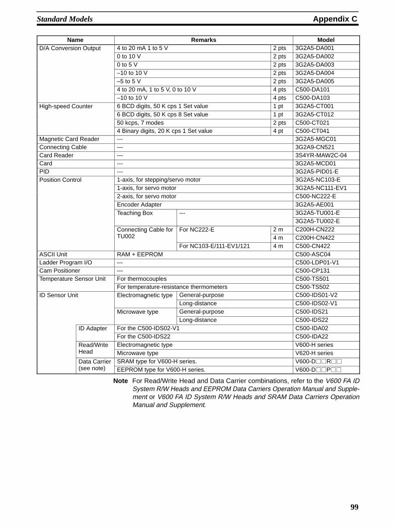
Appendix CStandard Models
99
Name ModelRemarksD/A Conversion Output 4 to 20 mA 1 to 5 V 2 pts 3G2A5-DA001
0 to 10 V 2 pts 3G2A5-DA0020 to 5 V 2 pts 3G2A5-DA003–10 to 10 V 2 pts 3G2A5-DA004–5 to 5 V 2 pts 3G2A5-DA0054 to 20 mA, 1 to 5 V, 0 to 10 V 4 pts C500-DA101–10 to 10 V 4 pts C500-DA103
High-speed Counter 6 BCD digits, 50 K cps 1 Set value 1 pt 3G2A5-CT001g6 BCD digits, 50 K cps 8 Set value 1 pt 3G2A5-CT01250 kcps, 7 modes 2 pts C500-CT0214 Binary digits, 20 K cps 1 Set value 4 pt C500-CT041
Magnetic Card Reader --- 3G2A5-MGC01Connecting Cable --- 3G2A9-CN521Card Reader --- 3S4YR-MAW2C-04Card --- 3G2A5-MCD01PID --- 3G2A5-PID01-EPosition Control 1-axis, for stepping/servo motor 3G2A5-NC103-E
1-axis, for servo motor 3G2A5-NC111-EV12-axis, for servo motor C500-NC222-EEncoder Adapter 3G2A5-AE001Teaching Box --- 3G2A5-TU001-Eg
3G2A5-TU002-EConnecting Cable forTU002
For NC222-E 2 m C200H-CN222gTU002 4 m C200H-CN422
For NC103-E/111-EV1/121 4 m C500-CN422ASCII Unit RAM + EEPROM C500-ASC04Ladder Program I/O --- C500-LDP01-V1Cam Positioner --- C500-CP131Temperature Sensor Unit For thermocouples C500-TS501
For temperature-resistance thermometers C500-TS502ID Sensor Unit Electromagnetic type General-purpose C500-IDS01-V2g y
Long-distance C500-IDS02-V1Microwave type General-purpose C500-IDS21y
Long-distance C500-IDS22ID Adapter For the C500-IDS02-V1 C500-IDA02
For the C500-IDS22 C500-IDA22Read/WriteH d
Electromagnetic type V600-H seriesHead Microwave type V620-H seriesData Carrier( )
SRAM type for V600-H series. V600-DR
(see note) EEPROM type for V600-H series. V600-DP
Note For Read/Write Head and Data Carrier combinations, refer to the V600 FA IDSystem R/W Heads and EEPROM Data Carriers Operation Manual and Supple-ment or V600 FA ID System R/W Heads and SRAM Data Carriers OperationManual and Supplement.
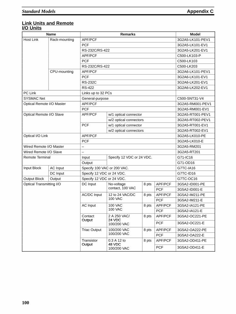
Appendix CStandard Models
100
Link Units and RemoteI/O Units
Name Remarks ModelHost Link Rack-mounting APF/PCF 3G2A5-LK101-PEV1g
PCF 3G2A5-LK101-EV1
RS-232C/RS-422 3G2A5-LK201-EV1
APF/PCF C500-LK103-P
PCF C500-LK103
RS-232C/RS-422 C500-LK203
CPU-mounting APF/PCF 3G2A6-LK101-PEV1g
PCF 3G2A6-LK101-EV1
RS-232C 3G2A6-LK201-EV1
RS-422 3G2A6-LK202-EV1
PC Link Links up to 32 PCs
SYSMAC Net General-purpose C500-SNT31-V4
Optical Remote I/O Master APF/PCF 3G2A5-RM001-PEV1
PCF 3G2A5-RM001-EV1
Optical Remote I/O Slave APF/PCF w/1 optical connector 3G2A5-RT001-PEV1
w/2 optical connectors 3G2A5-RT002-PEV1
PCF w/1 optical connector 3G2A5-RT001-EV1
w/2 optical connectors 3G2A5-RT002-EV1
Optical I/O Link APF/PCF 3G2A5-LK010-PE
PCF 3G2A5-LK010-E
Wired Remote I/O Master – 3G2A5-RM201
Wired Remote I/O Slave – 3G2A5-RT201
Remote Terminal Input Specify 12 VDC or 24 VDC. G71-IC16
Output
y
G71-OD16
Input Block AC Input Specify 100 VAC or 200 VAC. G7TC-IA16
DC Input Specify 12 VDC or 24 VDC. G7TC-ID16
Output Block Output Specify 12 VDC or 24 VDC. G7TC-OC16
Optical Transmitting I/O DC Input No-voltage100 VAC
8 pts APF/PCF 3G5A2-ID001-PEg gcontact, 100 VAC PCF 3G5A2-ID001-E
AC/DC Input 12 to 24 VAC/DC100 VAC
8 pts APF/PCF 3G5A2-IM211-PE100 VAC PCF 3G5A2-IM211-E
AC Input 100 VAC100 VAC
8 pts APF/PCF 3G5A2-IA121-PE100 VAC PCF 3G5A2-IA121-E
ContactOutput
2 A 250 VAC/24 VDC
8 pts APF/PCF 3G5A2-OC221-PEOutput 24 VDC
100/200 VAC PCF 3G5A2-OC221-E
Triac Output 100/200 VAC100/200 VAC
8 pts APF/PCF 3G5A2-OA222-PE100/200 VAC PCF 3G5A2-OA222-E
TransistorOutput
0.3 A 12 to 48 VDC
8 pts APF/PCF 3G5A2-OD411-PEOutput 48 VDC
100/200 VAC PCF 3G5A2-OD411-E
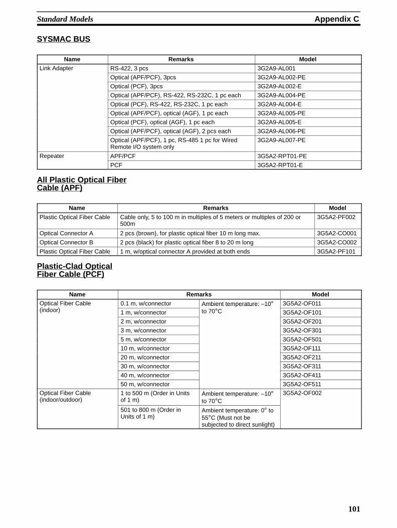
Appendix CStandard Models
101
SYSMAC BUS
Name Remarks ModelLink Adapter RS-422, 3 pcs 3G2A9-AL001
Optical (APF/PCF), 3pcs 3G2A9-AL002-PE
Optical (PCF), 3pcs 3G2A9-AL002-E
Optical (APF/PCF), RS-422, RS-232C, 1 pc each 3G2A9-AL004-PE
Optical (PCF), RS-422, RS-232C, 1 pc each 3G2A9-AL004-E
Optical (APF/PCF), optical (AGF), 1 pc each 3G2A9-AL005-PE
Optical (PCF), optical (AGF), 1 pc each 3G2A9-AL005-E
Optical (APF/PCF), optical (AGF), 2 pcs each 3G2A9-AL006-PE
Optical (APF/PCF), 1 pc, RS-485 1 pc for WiredRemote I/O system only
3G2A9-AL007-PE
Repeater APF/PCF 3G5A2-RPT01-PE
PCF 3G5A2-RPT01-E
All Plastic Optical FiberCable (APF)
Name Remarks Model
Plastic Optical Fiber Cable Cable only, 5 to 100 m in multiples of 5 meters or multiples of 200 or500m
3G5A2-PF002
Optical Connector A 2 pcs (brown), for plastic optical fiber 10 m long max. 3G5A2-CO001
Optical Connector B 2 pcs (black) for plastic optical fiber 8 to 20 m long 3G5A2-CO002
Plastic Optical Fiber Cable 1 m, w/optical connector A provided at both ends 3G5A2-PF101
Plastic-Clad OpticalFiber Cable (PCF)
Name Remarks ModelOptical Fiber Cable(i d )
0.1 m, w/connector Ambient temperature: –10° 3G5A2-OF011(indoor) 1 m, w/connector
Ambient tem erature: 10to 70°C 3G5A2-OF101
2 m, w/connector 3G5A2-OF201
3 m, w/connector 3G5A2-OF301
5 m, w/connector 3G5A2-OF501
10 m, w/connector 3G5A2-OF111
20 m, w/connector 3G5A2-OF211
30 m, w/connector 3G5A2-OF311
40 m, w/connector 3G5A2-OF411
50 m, w/connector 3G5A2-OF511
Optical Fiber Cable(indoor/outdoor)
1 to 500 m (Order in Unitsof 1 m)
Ambient temperature: –10°to 70°C
3G5A2-OF002
501 to 800 m (Order inUnits of 1 m)
Ambient temperature: 0° to55°C (Must not besubjected to direct sunlight)
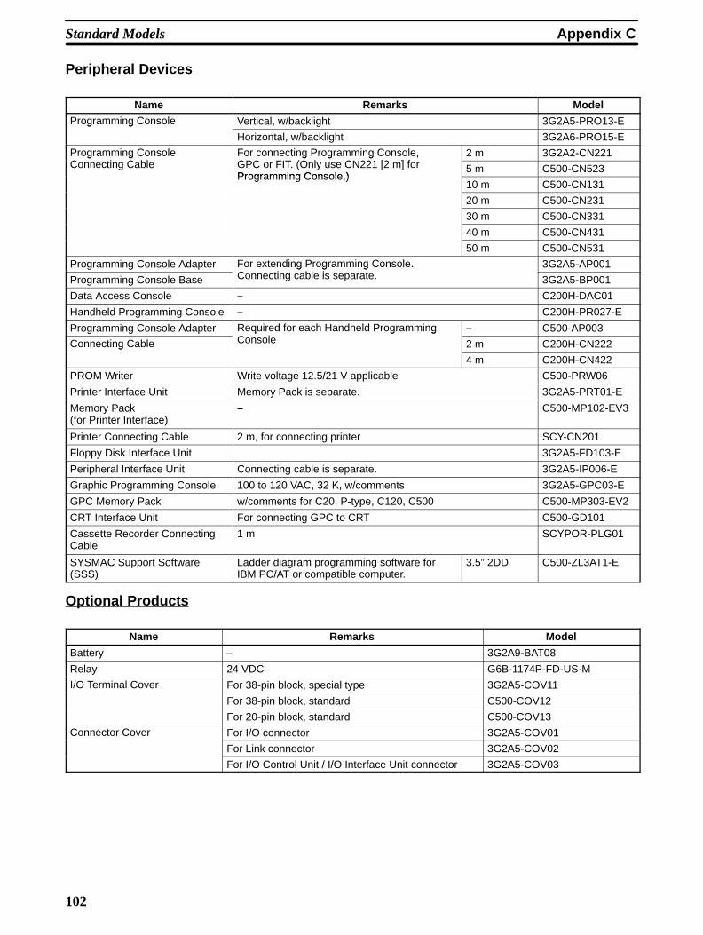
Appendix CStandard Models
102
Peripheral Devices
Name Remarks ModelProgramming Console Vertical, w/backlight 3G2A5-PRO13-Eg g
Horizontal, w/backlight 3G2A6-PRO15-E
Programming ConsoleC i C bl
For connecting Programming Console, GPC FIT (O l CN221 [2 ] f
2 m 3G2A2-CN221g gConnecting Cable
g g g ,GPC or FIT. (Only use CN221 [2 m] forProgramming Console )
5 m C500-CN523Programming Console.)
10 m C500-CN131
20 m C500-CN231
30 m C500-CN331
40 m C500-CN431
50 m C500-CN531
Programming Console Adapter For extending Programming Console.C i bl i
3G2A5-AP001
Programming Console Base
g g gConnecting cable is separate. 3G2A5-BP001
Data Access Console – C200H-DAC01
Handheld Programming Console – C200H-PR027-E
Programming Console Adapter Required for each Handheld ProgrammingC l
– C500-AP003
Connecting Cable
q g gConsole 2 m C200H-CN222g
4 m C200H-CN422
PROM Writer Write voltage 12.5/21 V applicable C500-PRW06
Printer Interface Unit Memory Pack is separate. 3G2A5-PRT01-E
Memory Pack(for Printer Interface)
– C500-MP102-EV3
Printer Connecting Cable 2 m, for connecting printer SCY-CN201
Floppy Disk Interface Unit 3G2A5-FD103-E
Peripheral Interface Unit Connecting cable is separate. 3G2A5-IP006-E
Graphic Programming Console 100 to 120 VAC, 32 K, w/comments 3G2A5-GPC03-E
GPC Memory Pack w/comments for C20, P-type, C120, C500 C500-MP303-EV2
CRT Interface Unit For connecting GPC to CRT C500-GD101
Cassette Recorder Connecting Cable
1 m SCYPOR-PLG01
SYSMAC Support Software(SSS)
Ladder diagram programming software forIBM PC/AT or compatible computer.
3.5” 2DD C500-ZL3AT1-E
Optional Products
Name Remarks Model
Battery – 3G2A9-BAT08
Relay 24 VDC G6B-1174P-FD-US-M
I/O Terminal Cover For 38-pin block, special type 3G2A5-COV11
For 38-pin block, standard C500-COV12
For 20-pin block, standard C500-COV13
Connector Cover For I/O connector 3G2A5-COV01
For Link connector 3G2A5-COV02
For I/O Control Unit / I/O Interface Unit connector 3G2A5-COV03

103
Glossary
Backplane A base to which Units are mounted to form a Rack. Backplanes provide aseries of connectors for these Units along with wiring to connect them to theCPU and Power Supply. Backplanes also provide connectors used toconnect them to other Backplanes. In some Systems, different Backplanesare used for different Racks; in other Systems, Racks differ only by the Unitsmounted to them.
back-up A copy of existing data which is valuable if data is accidentally erased.
bit The smallest piece of information that can be represented on a computer. Abit has the value of either zero or one, corresponding to the electrical signalsON and OFF. A bit is one binary digit.
central processing unit A device that is capable of storing a program and data, and executing the setof instructions contained in the program. In a PC System, the centralprocessing unit executes the program, processes I/O signals, communicateswith external devices, etc.
communication cable Cable used to transfer data between components of a control system andconforming to the RS-232C or RS-422 standards.
Control System All of the hardware and software components used to control other devices.A Control System includes the PC System, the PC programs, and all I/Odevices that are used to control or obtain feedback from the controlledsystem.
CPU An acronym for central processing unit.
CPU Backplane A Backplane used to create a CPU Rack.
CPU Rack Part of a Rack PC, the CPU Rack contains the CPU, a Power Supply, andother Units.
data area An area in the PC’s memory that is designed to hold a specific type of data,e.g., the LR area is designed to hold common data in a PC Link System.
data link Allows for the connection of up to 32 PCs in a Net Link System where each iscontributing information to a common memory area. Data links may beestablished in the LR and/or DM memory areas.
distributed control An automation concept in which control of each portion of an automatedsystem is located near the devices actually being controlled, i.e., control isdecentralized and “distributed” over the system. Distributed control is aconcept basic to PC Systems.
EEPROM [E(lectrically) E(rasable) P(rogrammable) R(ead) O(nly) M(emory)] A type ofROM in which stored data can be erased and reprogrammed. This isaccomplished using a special control lead connected to the EEPROM chipand can be done without having to remove the EEPROM chip from thedevice in which it is mounted.
EPROM [E(rasable) P(rogrammable) R(ead) O(nly) M(emory)] A type of ROM inwhich stored data can be erased, by ultraviolet light or other means, andreprogrammed.
Expansion I/O Unit An I/O Unit for a Package-type PC that provides more I/O points to the PC.
factory computer A general-purpose computer, usually quite similar to a business computer,that is used in automated factory control.
High-speed Counter A Special I/O Unit. A High Speed Counter Unit counts independently of thePC’s cycle time. This allows counting of very short, fast signals.
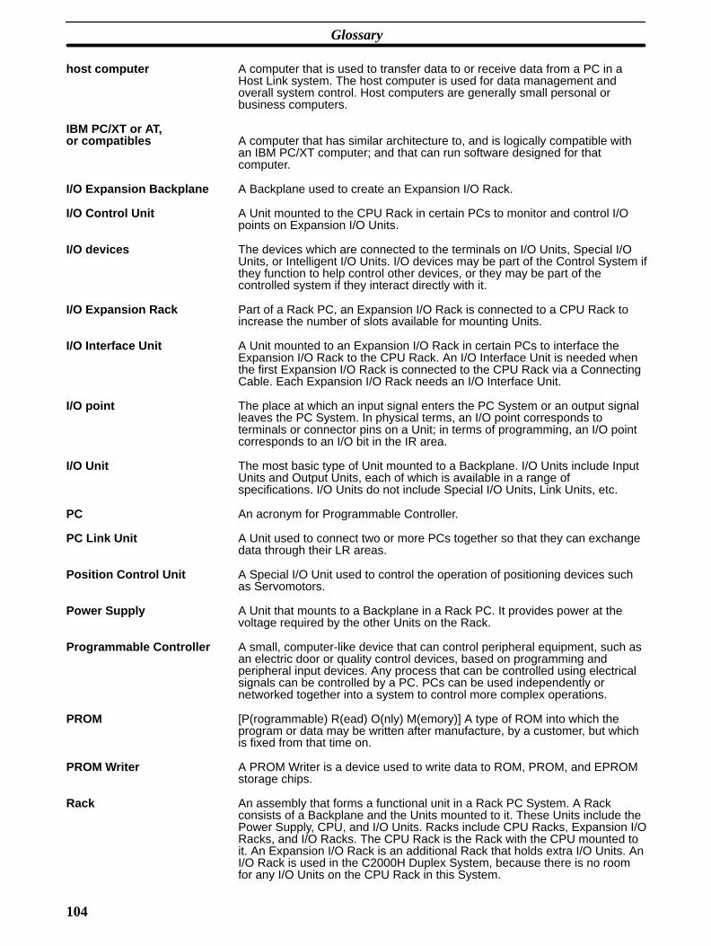
Glossary
104
host computer A computer that is used to transfer data to or receive data from a PC in aHost Link system. The host computer is used for data management andoverall system control. Host computers are generally small personal orbusiness computers.
IBM PC/XT or AT,or compatibles A computer that has similar architecture to, and is logically compatible with
an IBM PC/XT computer; and that can run software designed for thatcomputer.
I/O Expansion Backplane A Backplane used to create an Expansion I/O Rack.
I/O Control Unit A Unit mounted to the CPU Rack in certain PCs to monitor and control I/Opoints on Expansion I/O Units.
I/O devices The devices which are connected to the terminals on I/O Units, Special I/OUnits, or Intelligent I/O Units. I/O devices may be part of the Control System ifthey function to help control other devices, or they may be part of thecontrolled system if they interact directly with it.
I/O Expansion Rack Part of a Rack PC, an Expansion I/O Rack is connected to a CPU Rack toincrease the number of slots available for mounting Units.
I/O Interface Unit A Unit mounted to an Expansion I/O Rack in certain PCs to interface theExpansion I/O Rack to the CPU Rack. An I/O Interface Unit is needed whenthe first Expansion I/O Rack is connected to the CPU Rack via a ConnectingCable. Each Expansion I/O Rack needs an I/O Interface Unit.
I/O point The place at which an input signal enters the PC System or an output signalleaves the PC System. In physical terms, an I/O point corresponds toterminals or connector pins on a Unit; in terms of programming, an I/O pointcorresponds to an I/O bit in the IR area.
I/O Unit The most basic type of Unit mounted to a Backplane. I/O Units include InputUnits and Output Units, each of which is available in a range ofspecifications. I/O Units do not include Special I/O Units, Link Units, etc.
PC An acronym for Programmable Controller.
PC Link Unit A Unit used to connect two or more PCs together so that they can exchangedata through their LR areas.
Position Control Unit A Special I/O Unit used to control the operation of positioning devices suchas Servomotors.
Power Supply A Unit that mounts to a Backplane in a Rack PC. It provides power at thevoltage required by the other Units on the Rack.
Programmable Controller A small, computer-like device that can control peripheral equipment, such asan electric door or quality control devices, based on programming andperipheral input devices. Any process that can be controlled using electricalsignals can be controlled by a PC. PCs can be used independently ornetworked together into a system to control more complex operations.
PROM [P(rogrammable) R(ead) O(nly) M(emory)] A type of ROM into which theprogram or data may be written after manufacture, by a customer, but whichis fixed from that time on.
PROM Writer A PROM Writer is a device used to write data to ROM, PROM, and EPROMstorage chips.
Rack An assembly that forms a functional unit in a Rack PC System. A Rackconsists of a Backplane and the Units mounted to it. These Units include thePower Supply, CPU, and I/O Units. Racks include CPU Racks, Expansion I/ORacks, and I/O Racks. The CPU Rack is the Rack with the CPU mounted toit. An Expansion I/O Rack is an additional Rack that holds extra I/O Units. AnI/O Rack is used in the C2000H Duplex System, because there is no roomfor any I/O Units on the CPU Rack in this System.
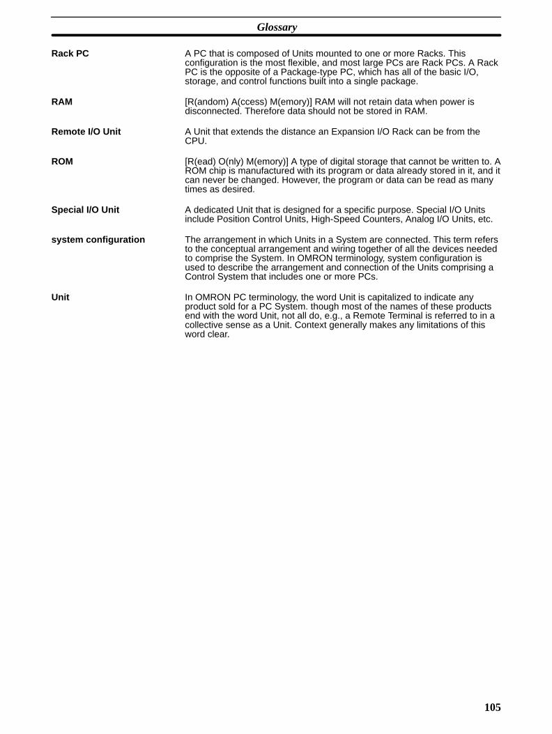
Glossary
105
Rack PC A PC that is composed of Units mounted to one or more Racks. Thisconfiguration is the most flexible, and most large PCs are Rack PCs. A RackPC is the opposite of a Package-type PC, which has all of the basic I/O,storage, and control functions built into a single package.
RAM [R(andom) A(ccess) M(emory)] RAM will not retain data when power isdisconnected. Therefore data should not be stored in RAM.
Remote I/O Unit A Unit that extends the distance an Expansion I/O Rack can be from theCPU.
ROM [R(ead) O(nly) M(emory)] A type of digital storage that cannot be written to. AROM chip is manufactured with its program or data already stored in it, and itcan never be changed. However, the program or data can be read as manytimes as desired.
Special I/O Unit A dedicated Unit that is designed for a specific purpose. Special I/O Unitsinclude Position Control Units, High-Speed Counters, Analog I/O Units, etc.
system configuration The arrangement in which Units in a System are connected. This term refersto the conceptual arrangement and wiring together of all the devices neededto comprise the System. In OMRON terminology, system configuration isused to describe the arrangement and connection of the Units comprising aControl System that includes one or more PCs.
Unit In OMRON PC terminology, the word Unit is capitalized to indicate anyproduct sold for a PC System. though most of the names of these productsend with the word Unit, not all do, e.g., a Remote Terminal is referred to in acollective sense as a Unit. Context generally makes any limitations of thisword clear.
107
Index
A
AC Input,
Ambient Temperature of PC,
applications, precautions,
ASCII,
B
BackplaneExpansion I/O, I/O Expansion, mounting Units to, ,
Bleeder Resistor,
Block, Terminal,
C
Cablepower, twisted pair,
Clearance, Between PC Racks,
Conditions, Installation,
Conduit,
ConnectionsI/O Units, PC,
control components,
Cooling, PC,
CPU, , , and Memory Packs, , and RAM Packs, and ROM Packs, Backplane, connector, core of PC, Power Supply, , Rack,
CPU Rack, connecting to another Backplane,
Currentinput leakage, output leakage, output surge,
Current Consumption,
Cycle Time,
D
DC Input Units,
Duct, Wiring,
E
Electrical Noise,
Electrostatic Charge,
Emergency Stop,
Environment, Installation,
EPROM Chip, mounting to ROM PAck,
Examples, wiring,
Expansion I/O Backplane,
Expansion I/O Power Supply,
Expansion I/O Rack, , ,
Expansion I/O Racks, mounting Units to,
F
Factory Computer,
Fan, cooling,
G
Grounding,
Grounding During PC Installation,
H
High Power Equipment, and PC installation,
Humidity,
I
I/O Connections,
I/O Control Unit, ,
I/O Interface Unit, ,
I/O Points, ,
I/O Power Supply,
I/O Unit, , Link, power consumption, mounting, mounting to Backplane, power consumption,

Index
108
Remote, power consumption, shapes,
A-shape, B-shape, C-shape, D-shape, E-shape,
Special, power consumption,
I/O Unit 3G2A5–PS213–E,
I/O Unit 3G2A5–PS223–E,
Inductive Load Surge Suppressor,
Input Devices,
Input Leakage Current,
InstallationEnvironment, Memory Pack to the CPU,
installation, precautions,
Interlock Circuits,
L
Limit Switch,
M
Memory Pack, installation,
Memory Packs, ,
MountingEPROM Chip to ROM Pack, I/O Units, PC,
Mounting Units,
N
Noise, electrical,
Noise, Preventing,
O
operating environment, precautions,
Output Devices,
Output Leakage Current,
Output Surge Current,
Output Units,
P
PCambient temperature,
and input devices, and output devices, clearance between racks, components, connections, cooling the, general, how it operates, I/O Unit mounting, in a Control System, installation environment, its role, mounting requirements,
Peripheral Device Connector,
Photoelectric Switch,
Position Control System,
Position Control Unit, power consumption,
Power Cables,
Power Consideration,
Power Consumption, Units, , ,
Power Failure, detection signal,
Power Reset,
Power Source,
Power Supplies,
Power Supply, Backplane mounting, CPU, , Expansion I/O, I/O, in a CPU Rack, in block diagram, output capacity,
Power Supply Output,
precautionsapplications, general, operating environment, safety,
Preventing Noise,
process control computer,
Programmable Controller, flow chart,
Programmable Controller (also see PC), block diagram,
Programmable Controller (See also PC),
PROM,
Proximity Switch,
R
Rack, PC,
RAM, ,
RAM Pack,
Index
109
Remote I/O UnitMaster, Slave,
Reset, Power,
Residual Voltage,
Resistor, Bleeder,
ROM Pack,
S
Safety Considerations,
safety precautions. See precautions
scanning cycle,
Screw, Terminal Block,
Sensors, in control system,
Servomotor,
Solenoid,
Special I/O Unit, number used,
Static Electricity, preventing,
stepping motor,
Switchin control system, limit, photoelectric, proximity, pushbutton,
System Configuration,
T
Temperature, PC,
Terminal Block,
Transistor Output Residual Voltage,
Twisted Pair Cable,
U
Underground, Wires,
UnitDC Input, I/O Control, , , I/O Interface, , , I/O, general, mounting, Output, power consumption of, ,
V-W
Voltage, residual,
Wire, shared, problems of,
Wiringduct, power source to PC,
Wiring Examples,
Word,
Writeprogram to RAM Pack, PROM,
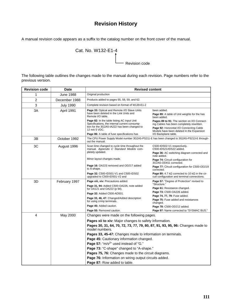
111
Revision History
A manual revision code appears as a suffix to the catalog number on the front cover of the manual.
Cat. No. W132-E1-4
Revision code
The following table outlines the changes made to the manual during each revision. Page numbers refer to theprevious version.
Revision code Date Revised content
1 June 1988 Original production
2 December 1988 Products added to pages 55, 58, 59, and 62.
3 July 1990 Complete revision based on format of W139-E1-2
3A April 1991 Page 33: Optical and Remote I/O Slave Unitshave been deleted in the Link Units andRemote I/O table.
Page 82: In the table listing AC Input UnitSpecifications, the internal current consump-tion for the 3G2A5-IA222 has been changed to12 mA 5 VDC.
Page 86: A table of fuse specifications has
been added.Page 89: A table of Unit weights for the hasbeen added.Pages 89 to 91: The section on I/O Connect-ing Cables has been completely rewritten.Page 92: Horizontal I/O Connecting CableModels have been deleted in the ExpansionI/O Backplane table.
3B October 1992 The CPU Power Supply Model number 3G2A5-PS211-E has been changed to 3G2A5-PS213-E through-out the manual.
3C August 1996 Scan time changed to cycle time throughout themanual. Appendix C Standard Models com-pletely updated.
Minor layout changes made.
Page 16: OA223 removed and OD217 addedto A-shape.
Page 32: C500-IDS01-V1 and C500-IDS02upgraded to C500-IDS01-V2 and
C500-IDS02-V1 respectively.C500-IDS21/IDS22 added.Page 36: AC switching diagram corrected andnote added.Page 74: Circuit configuration for3G2A5-OD411 corrected.Page 77: Circuit configuration for C500-OD219corrected.Page 80: 4.7 kΩ corrected to 10 kΩ in the cir-cuit configuration and terminal connections.
3D February 1997 Page xiii, xiv: Precautions added.
Page 31, 94: Added C500-OA226, note addedfor OA121 and OA222 (p 94).
Page 32: Added C500-AD501.
Page 33, 46, 47: Changed/Added descriptionfor using crimp terminals.
Page 45: Added caution.
Page 55: Removed caution.
Page 57: “Degree of Protection” revised to“Structure.”Page 61: Resistance changed.Page 73: C500-OA226 added.Page 74, 77, 79: Fuse added.Page 75: Fuse added and resistanceschanged.Page 78: C500-OD212 added.Page 97: Name corrected to “SYSMAC BUS.”
4 May 2000 Changes were made on the following pages.
Pages xii to xiv: Major changes to safety information.Pages 30, 31, 64, 70, 72, 73, 77, 79, 80, 87, 91, 93, 95, 96: Changes made tomodel numbers.Pages 33, 45-47: Changes made to information on terminals.Page 45: Cautionary information changed.Page 57: “m/s2” used instead of “G.”Page 73: “C-shape” changed to “A-shape.”Pages 75, 76: Changes made to the circuit diagrams.Page 76: Information on wiring output circuits added.Page 87: Row added to table.