lpc2138 dev
TRANSCRIPT
7/23/2019 Lpc2138 Dev
http://slidepdf.com/reader/full/lpc2138-dev 1/8
http://www.robokits.co.in
http://www.robokitsworld.com Page 1
ARM7 LPC2138 Development Board
ARM7 LPC2138
Development Board
Users Manual
Robokits Indiahttp://www.robokits.co.in
Robokits Worldhttp://www.robokitsworld.com
7/23/2019 Lpc2138 Dev
http://slidepdf.com/reader/full/lpc2138-dev 2/8
http://www.robokits.co.in
http://www.robokitsworld.com Page 2
ARM7 LPC2138 Development Board
Thank you for purchasing the ARM7 LPC2138 Development Board. This unit has been carefully
engineered and tested to provide superior performance. This document covers the features and operation of theARM7 LPC2138 Development Board.
This is an easy-to-use board using the popular NXP(Phillips) LPC2138 microcontroller. The boardincludes everything you need to learn, develop or using for a any application. It is ideal for any kind ofautonomous or manual controlled robot.
Features• Keil MCB2130 based design
• Removable Processor Board
• Small Size: 75mm*60mm
• ISP programming through inbuilt Booloader of LPC21XX series
• Power On/Off Switch• 8 indicator led's with separate jumpers for enable/disable
• On board 3.3V regulator
• Rest and INT1 switches
• Potentiometer for ADC1
• JTAG standard port
• All port pins accessible through standard 8bit 10 pin connector
• 4 DC motor driver interface with PWM.
• PWM for motor selectable through Jumpers
• Optional power pins through jumpers to reduce power consumption
• Capacitor filters at all power pins to reduce glitches
• DTR, RTS signals for reset and bootloader enter point
•
Dual UART interface UART0 & UART1• UART0/Programmer selection switch on ISP Programmer
• Simple 8 wire interface
• Compatible with LPC2138 development board
• Programmer compatible with Flash magic, LPC21ISP & LPC2000 flash utility(NXP)
This Product Includes• ARM7 LPC2138 Development Board
• CD containing all required software's and sample codes in Keil C, Relview and WinARM
7/23/2019 Lpc2138 Dev
http://slidepdf.com/reader/full/lpc2138-dev 3/8
http://www.robokits.co.in
http://www.robokitsworld.com Page 3
ARM7 LPC2138 Development Board
Jumper settings
• J2 - AV: Analog Voltage for AIN0: connects the POT1 potentiometer to the analog input AIN0.
• J3 - 3.3V: Supply Voltage for CPU: connects the 3.3V Supply Voltage to the CPU.
• J4 - VBAT: Supply Voltage for CPU: connects battery Supply Voltage to the CPU.
• J5 - V3A: Analog Reference Voltage for CPU: connects the 3.3V Supply Voltage to the CPU AnalogReference Input V3A.
• J7 - INT1: Enable Push Button INT1: connects the push button INT1 to the CPU I/O pin P0.14 (EINT1input). Pushing the button generates a low signal.
• J9 - JTAG: Enable JTAG Interface: enables the JTAG interface. This jumper is required for ISP flashingand for debugging via Keil ULINK or other JTAG debuggers.
• J11 - VREF: A/D Converter Reference Voltage: connects 3.3V Supply Voltage VREF of the CPU.
• J12 & J13: PWM Select for MOTOR1 PORT
• J14 & J15: PWM Select for MOTOR2 PORT
• J16 to J23: LED Select on P1.16 to P1.23 respectively
Setting up the Board
Providing Power Supply
• You can provide the power supply to the board from any DC source from 4V to 20V.
• The microcontroller is preprogrammed for Blinking LED’s. This is the default program provided on CD infolder named GPIO.
• To power up the board using any DC source use VDD terminal as +VE terminal and GND as –VE terminal.
• Be careful while applying power otherwise the regulator IC will blow up.
7/23/2019 Lpc2138 Dev
http://slidepdf.com/reader/full/lpc2138-dev 4/8
http://www.robokits.co.in
http://www.robokitsworld.com Page 4
ARM7 LPC2138 Development Board
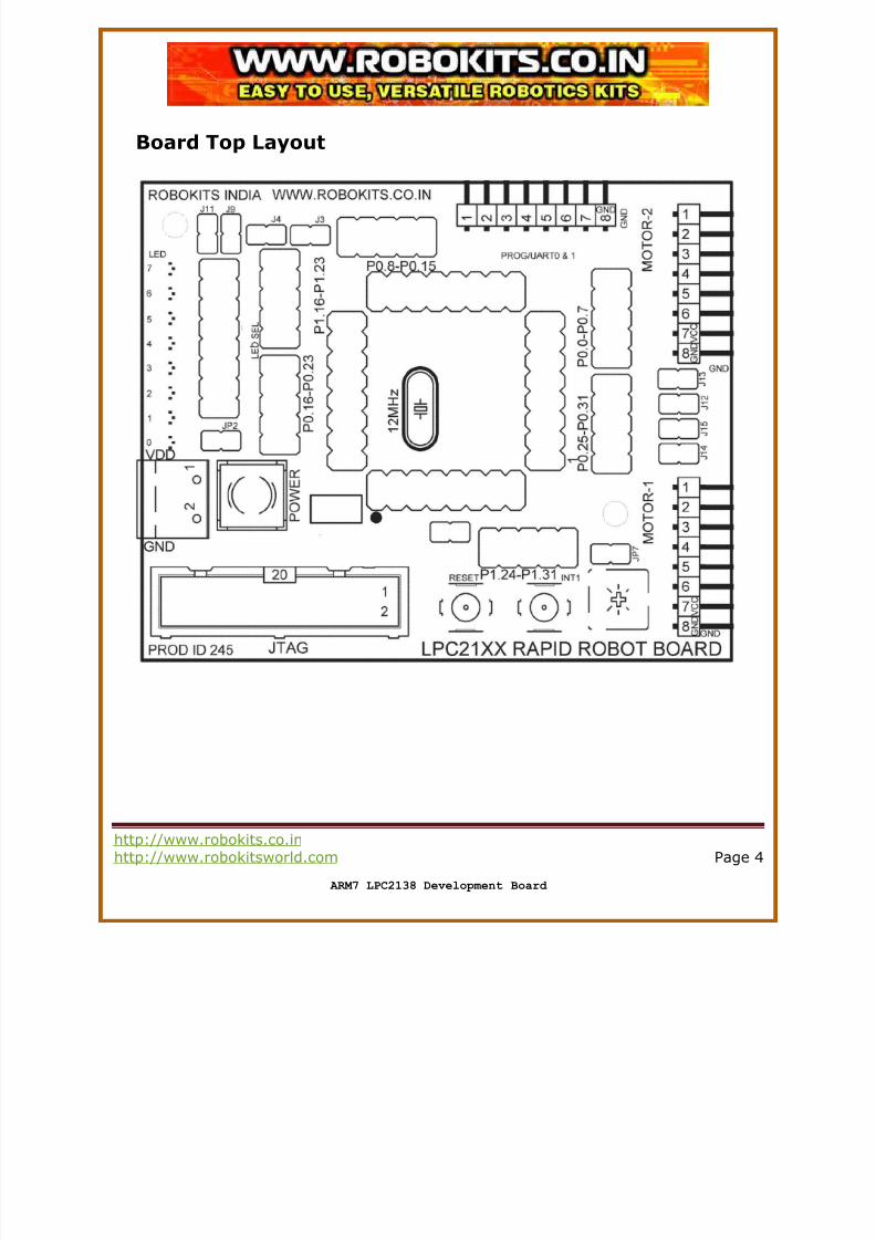
Board Top Layout
7/23/2019 Lpc2138 Dev
http://slidepdf.com/reader/full/lpc2138-dev 5/8
http://www.robokits.co.in
http://www.robokitsworld.com Page 5
ARM7 LPC2138 Development Board
Switches
• There are two small and one big switch on the board to facilitate user.
• The toggle switch written with POWER on the top is to control power supply to the board.
• The one written Reset at bottom is a Reset switch for microcontroller.
• Switch named INT1 is connected to external interrupt pin INT1on LPC2138 for general use.
• These switches do not affect the operation of the pins they are connected with. So, you can use thismicrocontroller I/O pins for other use also.
LED’s
• There are eight LED’s on the board.
• Eight led’s named LED0 to LED7 are connected to P1.16 to P1.23 respectively.
• All LED’s are selectable through individual jumpers (J16 to J23) so that those pins can be used for other
external purpose.• Put respective jumper to use the Pin as normal I/O pin.
ISP (In System Programming)/UART Connector
• 8 pin male header denoted by PROG/UART0 & 1 on the board is used to program & communicate withLPC2138 board.
• The pins are connected to RX1, TX1, RST, P0.14, RX0, TX0, VCC, GND.
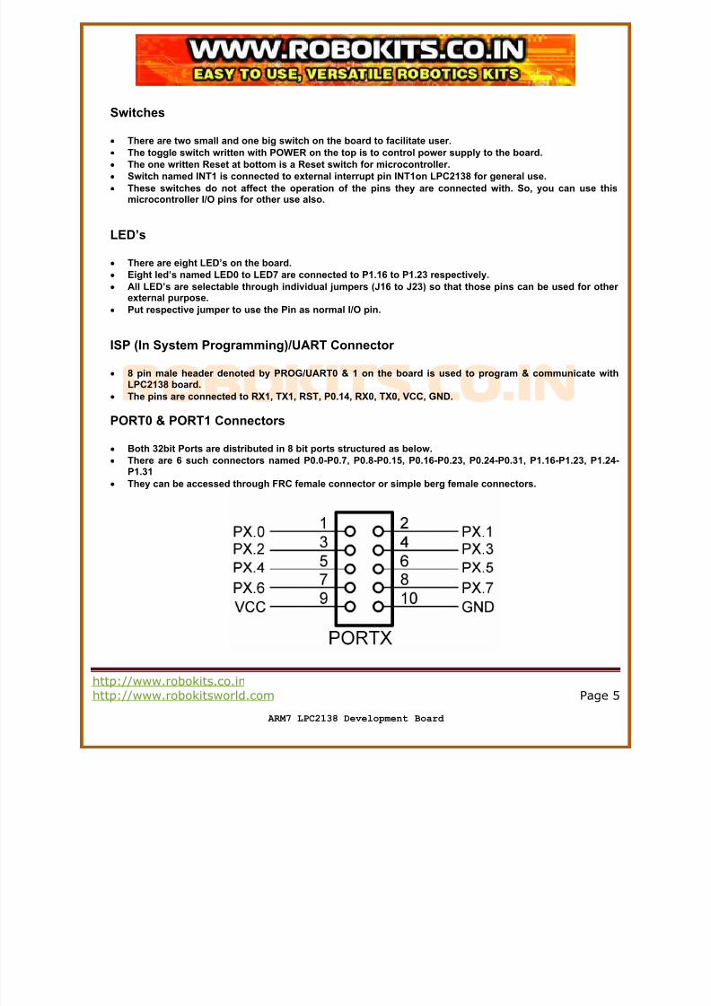
PORT0 & PORT1 Connectors
• Both 32bit Ports are distributed in 8 bit ports structured as below.• There are 6 such connectors named P0.0-P0.7, P0.8-P0.15, P0.16-P0.23, P0.24-P0.31, P1.16-P1.23, P1.24
P1.31
• They can be accessed through FRC female connector or simple berg female connectors.
7/23/2019 Lpc2138 Dev
http://slidepdf.com/reader/full/lpc2138-dev 6/8
http://www.robokits.co.in
http://www.robokitsworld.com Page 6
ARM7 LPC2138 Development Board
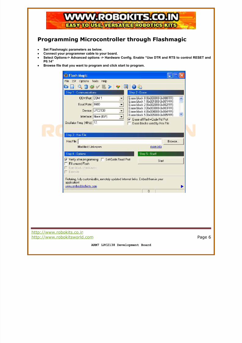
Programming Microcontroller through Flashmagic
•
Set Flashmagic parameters as below.• Connect your programmer cable to your board.
• Select Options-> Advanced options -> Hardware Config. Enable “Use DTR and RTS to control RESET andP0.14”
• Browse file that you want to program and click start to program.
7/23/2019 Lpc2138 Dev
http://slidepdf.com/reader/full/lpc2138-dev 7/8
http://www.robokits.co.in
http://www.robokitsworld.com Page 7
ARM7 LPC2138 Development Board
Sample codes and WINARM
•
Sample codes are provided in WinARM, Keil C & Realview compilers.• Install WinARM to C:\ so that WinARM bin folder is located at c:\winarm\bin.
• Right click on my computer and select advanced tab. Click on environment variables.
• Search for path variable and add ;C:\WinARM\bin;C:\WinARM\utils\bin;
• Open Programmers notepad editor from WinARM/pn/pn.exe.
• Open any sample code and click on Tools->program while your programmer is connected and board ispowered on.
• It will directly program your microcontroller with respective code.
• You can change sample codes written in C in Programmers notepad. Click make all and then program.
7/23/2019 Lpc2138 Dev
http://slidepdf.com/reader/full/lpc2138-dev 8/8
http://www.robokits.co.in
http://www.robokitsworld.com Page 8
ARM7 LPC2138 Development Board
Service and SupportService and support for this product are available from Robokits India. The Robokits Web site
(http://www.robokits.co.in) maintains current contact information for all Robokits products.
Limitations and WarrantyThe ARM7 LPC2138 Development Board is intended for personal experimental and amusement use and in no caseshould be used where the health or safety of persons may depend on its proper operation. Robokits provides nowarrantee of suitability or performance for any purpose for the product. Use of the product software and or hardware iswith the understanding that any outcome whatsoever is at the users own risk. Robokits sole guarantee is that the softwareand hardware perform in compliance with this document at the time it was shipped to the best of our ability givenreasonable care in manufacture and testing. All products are tested for their best performance before shipping, and no
warranty or guarantee is provided on any of them. Of course the support is available on all of them for no cost.
Disclaimer
Copyright © Robokits India, 2008
Neither the whole nor any part of the information contained in, or the product described in this manual, may be adapted oreproduced in any material or electronic form without the prior written consent of the copyright holder.
This product and its documentation are supplied on an as-is basis and no warranty as to their suitability for any particularpurpose is either made or implied.
This document provides preliminary information that may be subject to change without notice.