ni accelerometer principles
TRANSCRIPT
8/4/2019 Ni Accelerometer Principles
http://slidepdf.com/reader/full/ni-accelerometer-principles 1/4
Document Type: Prentice Hall
Author: Curtis D. JohnsonBook: Process Control Instrumentation Technology
Copyright: 1997ISBN: 0-13-441305-9
NI Supported: No
Accelerometer Principles
Overview
This tutorial is part of the National Instruments Measurement Fundamentals series. Each tutorial in this series will
teach you a specific topic of common measurement applications by explaining theoretical concepts and providing
practical examples. There are several physical processes that can be used to develop a sensor to measure
acceleration. In applications that involve flight, such as aircraft and satellites, accelerometers are based onproperties of rotating masses. In the industrial world, however, the most common design is based on a
combination of Newton's law of mass acceleration and Hooke's law of spring action.
Table of Contents
1. Spring-Mass System
2. Natural Frequency and Damping 3. Vibration Effects
4. Relevant NI Products
5. Buy the Book
Spring-Mass System
Newton's law simply states that if a mass, m, is undergoing an acceleration, a, then there must be a force F acting
on the mass and given by F = ma. Hooke's law states that if a spring of spring constant k is stretched (extended)from its equilibrium position for a distance D x , then there must be a force acting on the spring given by F = kDx.
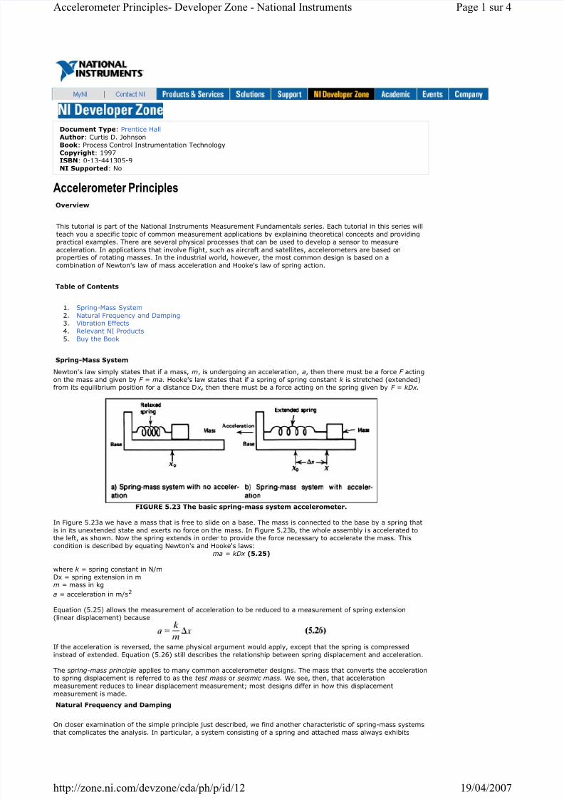
FIGURE 5.23 The basic spring-mass system accelerometer.
In Figure 5.23a we have a mass that is free to slide on a base. The mass is connected to the base by a spring that
is in its unextended state and exerts no force on the mass. In Figure 5.23b, the whole assembly is accelerated tothe left, as shown. Now the spring extends in order to provide the force necessary to accelerate the mass. This
condition is described by equating Newton's and Hooke's laws:ma = kDx (5.25)
where k = spring constant in N/m
Dx = spring extension in mm = mass in kg
a = acceleration in m/s2
Equation (5.25) allows the measurement of acceleration to be reduced to a measurement of spring extension
(linear displacement) because
If the acceleration is reversed, the same physical argument would apply, except that the spring is compressed
instead of extended. Equation (5.26) still describes the relationship between spring displacement and acceleration.
The spring-mass principle applies to many common accelerometer designs. The mass that converts the accelerationto spring displacement is referred to as the test mass or seismic mass. We see, then, that acceleration
measurement reduces to linear displacement measurement; most designs differ in how this displacement
measurement is made.
Natural Frequency and Damping
On closer examination of the simple principle just described, we find another characteristic of spring-mass systems
that complicates the analysis. In particular, a system consisting of a spring and attached mass always exhibits
Page 1 sur 4Accelerometer Principles- Developer Zone - National Instruments
19/04/2007http://zone.ni.com/devzone/cda/ph/p/id/12
8/4/2019 Ni Accelerometer Principles
http://slidepdf.com/reader/full/ni-accelerometer-principles 2/4
oscillations at some characteristic natural frequency. Experience tells us that if we pull a mass back and then
release it (in the absence of acceleration), it will be pulled back by the spring, overshoot the equilibrium, and
oscillate back and forth. Only friction associated with the mass and base eventually brings the mass to rest. Any
displacement measuring system will respond to this oscillation as if an actual acceleration occurs. This naturalfrequency is given by
where f N = natural frequency in Hz
k = spring constant in N/m
m = seismic mass in kg
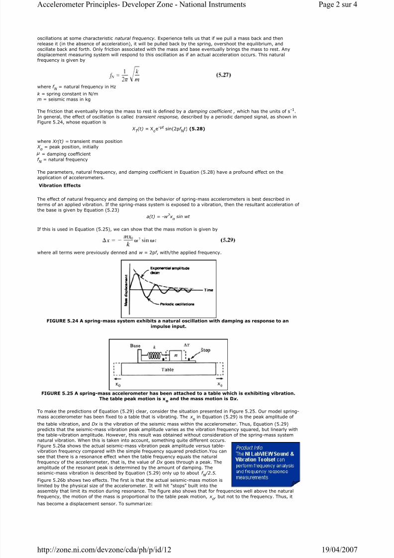
The friction that eventually brings the mass to rest is defined by a damping coefficient , which has the units of s-1.
In general, the effect of oscillation is called transient response, described by a periodic damped signal, as shown inFigure 5.24, whose equation is
X T (t) = X
oe-t sin(2pf
Nt ) (5.28)
where Xr(t) = transient mass position
X o = peak position, initially
= damping coefficient
f N
= natural frequency
The parameters, natural frequency, and damping coefficient in Equation (5.28) have a profound effect on the
application of accelerometers.
Vibration Effects
The effect of natural frequency and damping on the behavior of spring-mass accelerometers is best described in
terms of an applied vibration. If the spring-mass system is exposed to a vibration, then the resultant acceleration of
the base is given by Equation (5.23)
a(t) = -w 2 x o sin wt
If this is used in Equation (5.25), we can show that the mass motion is given by
where all terms were previously denned and w = 2pf , with/the applied frequency.
FIGURE 5.24 A spring-mass system exhibits a natural oscillation with damping as response to an
impulse input.
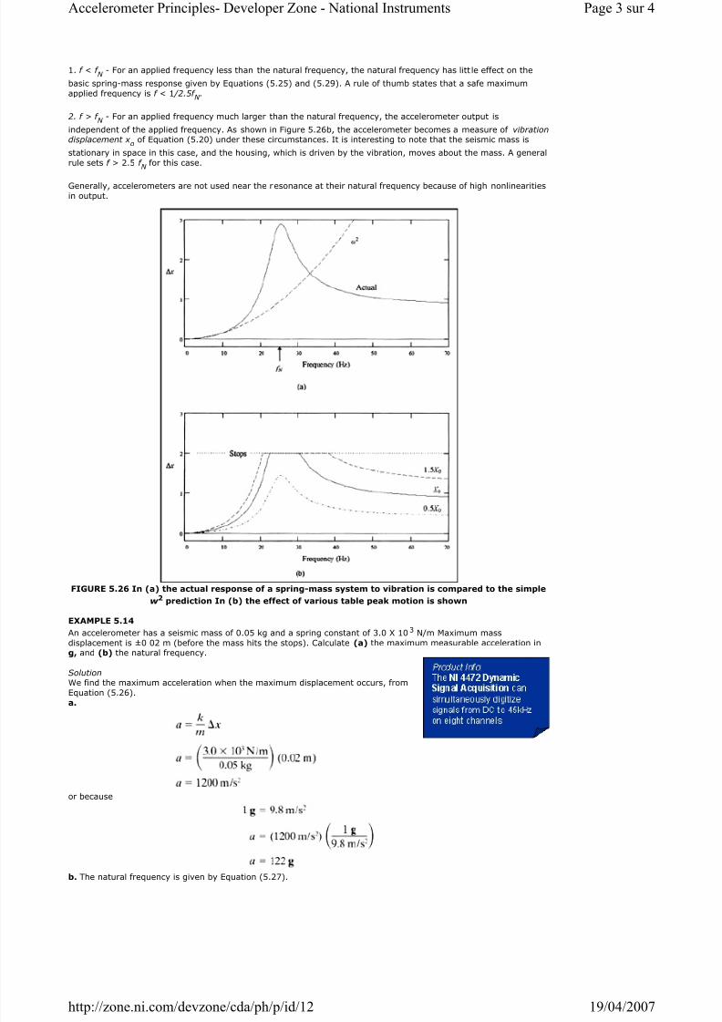
FIGURE 5.25 A spring-mass accelerometer has been attached to a table which is exhibiting vibration.The table peak motion is x
o and the mass motion is D x .
To make the predictions of Equation (5.29) clear, consider the situation presented in Figure 5.25. Our model spring-
mass accelerometer has been fixed to a table that is vibrating. The x o
in Equation (5.29) is the peak amplitude of
the table vibration, and Dx is the vibration of the seismic mass within the accelerometer. Thus, Equation (5.29)
predicts that the seismic-mass vibration peak amplitude varies as the vibration frequency squared, but linearly with
the table-vibration amplitude. However, this result was obtained without consideration of the spring-mass systemnatural vibration. When this is taken into account, something quite different occurs.
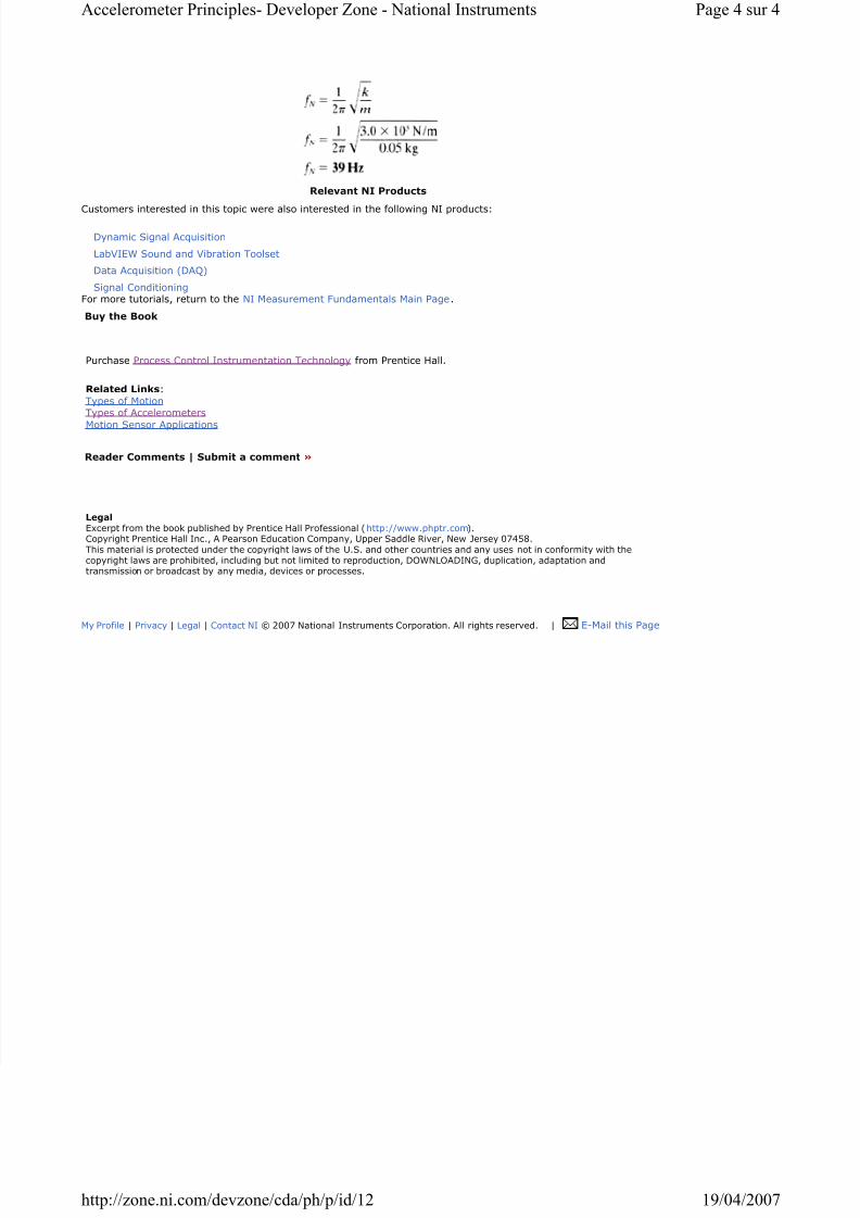
Figure 5.26a shows the actual seismic-mass vibration peak amplitude versus table-vibration frequency compared with the simple frequency squared prediction.You can
see that there is a resonance effect when the table frequency equals the natural
frequency of the accelerometer, that is, the value of Dx goes through a peak. The
amplitude of the resonant peak is determined by the amount of damping. Theseismic-mass vibration is described by Equation (5.29) only up to about f
N /2.5.
Figure 5.26b shows two effects. The first is that the actual seismic-mass motion is
limited by the physical size of the accelerometer. It will hit "stops" built into theassembly that limit its motion during resonance. The figure also shows that for frequencies well above the natural
frequency, the motion of the mass is proportional to the table peak motion, x o , but not to the frequency. Thus, it
has become a displacement sensor. To summarize:
Page 2 sur 4Accelerometer Principles- Developer Zone - National Instruments
19/04/2007http://zone.ni.com/devzone/cda/ph/p/id/12
8/4/2019 Ni Accelerometer Principles
http://slidepdf.com/reader/full/ni-accelerometer-principles 3/4
1. f < f N - For an applied frequency less than the natural frequency, the natural frequency has litt le effect on the
basic spring-mass response given by Equations (5.25) and (5.29). A rule of thumb states that a safe maximum
applied frequency is f < 1 /2.5f N .
2. f > f N - For an applied frequency much larger than the natural frequency, the accelerometer output is
independent of the applied frequency. As shown in Figure 5.26b, the accelerometer becomes a measure of vibrationdisplacement x
oof Equation (5.20) under these circumstances. It is interesting to note that the seismic mass is
stationary in space in this case, and the housing, which is driven by the vibration, moves about the mass. A general
rule sets f > 2.5 f N
for this case.
Generally, accelerometers are not used near the resonance at their natural frequency because of high nonlinearities
in output.
FIGURE 5.26 In (a) the actual response of a spring-mass system to vibration is compared to the simple
w 2 prediction In (b) the effect of various table peak motion is shown
EXAMPLE 5.14
An accelerometer has a seismic mass of 0.05 kg and a spring constant of 3.0 X 10³ N/m Maximum mass
displacement is ±0 02 m (before the mass hits the stops). Calculate (a) the maximum measurable acceleration ing, and (b) the natural frequency.
Solution We find the maximum acceleration when the maximum displacement occurs, from
Equation (5.26).
a.
or because
b. The natural frequency is given by Equation (5.27).
Page 3 sur 4Accelerometer Principles- Developer Zone - National Instruments
19/04/2007http://zone.ni.com/devzone/cda/ph/p/id/12
8/4/2019 Ni Accelerometer Principles
http://slidepdf.com/reader/full/ni-accelerometer-principles 4/4
Relevant NI Products
Customers interested in this topic were also interested in the following NI products:
For more tutorials, return to the NI Measurement Fundamentals Main Page.
Buy the Book
Purchase Process Control Instrumentation Technology from Prentice Hall.
Related Links:
Types of Motion Types of Accelerometers
Motion Sensor Applications
Reader Comments | Submit a comment »
Legal Excerpt from the book published by Prentice Hall Professional (http://www.phptr.com).Copyright Prentice Hall Inc., A Pearson Education Company, Upper Saddle River, New Jersey 07458.This material is protected under the copyright laws of the U.S. and other countries and any uses not in conformity with thecopyright laws are prohibited, including but not limited to reproduction, DOWNLOADING, duplication, adaptation andtransmission or broadcast by any media, devices or processes.
Dynamic Signal Acquisition
LabVIEW Sound and Vibration Toolset
Data Acquisition (DAQ)
Signal Conditioning
My Profile | Privacy | Legal | Contact NI © 2007 National Instruments Corporation. All rights reserved. | E-Mail this Page
Page 4 sur 4Accelerometer Principles- Developer Zone - National Instruments
19/04/2007http://zone ni com/devzone/cda/ph/p/id/12