pneumatic פניאומטיקה פניאומטיקה. crouzet pneumatic training במצגת זו...
TRANSCRIPT
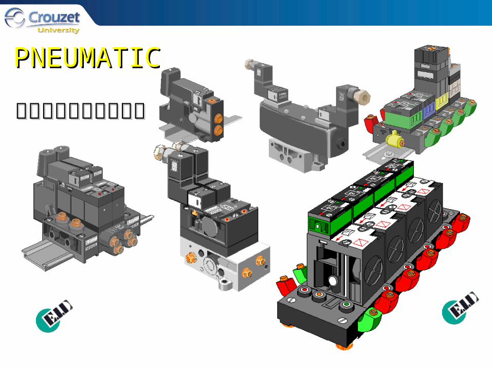
PNEUMATIPNEUMATICC
פניאומטיקהפניאומטיקה
Crouzet Pneumatic Crouzet Pneumatic TrainingTrainingבמצגת זו נעבור :במצגת זו נעבור :
Copyright, 1996 © Dale Carnegie & Associates, Inc.
אינפורמציה כלליתאינפורמציה כללית•פונקציות לוגיות בסיסיותפונקציות לוגיות בסיסיות •• P.A.C. SEQUENCERSP.A.C. SEQUENCERS• PERIPHERAL COMPONENTSPERIPHERAL COMPONENTSפתרון בעיותפתרון בעיות •
מבואמבוא•
סימניםסימנים •
מבוא
בקרה פניאומטית:בקרה פניאומטית:הפניאומטיקה שמוצעת ע"י קרוזט משמשת לבקרה של הפניאומטיקה שמוצעת ע"י קרוזט משמשת לבקרה של פונקציות במכונות תהליכים ורובוטיקה המופעלים אויר. פונקציות במכונות תהליכים ורובוטיקה המופעלים אויר.
קרוזט היא ספקית מובילה של בקרה פניאומטית קרוזט היא ספקית מובילה של בקרה פניאומטית באירופה ובארה"ב.באירופה ובארה"ב.
Specialized circuits of purpose built logic Specialized circuits of purpose built logic and stepping elements provide timing, and stepping elements provide timing, sensing and sequencing of all machine sensing and sequencing of all machine processes. processes.

אינפורמציה כללית
בבקרה פניאומטית נעדיף להשתמש ביחידות בבקרה פניאומטית נעדיף להשתמש ביחידות שמאפשרות זמן רב ככל האפשר בין שירות לשירות שמאפשרות זמן רב ככל האפשר בין שירות לשירות
ובדרגת אמינות גבוהה. היישומים יכולים להיות ובדרגת אמינות גבוהה. היישומים יכולים להיות במקומות של לחות גבוהה,לכלוך,סביבה מגנטית או במקומות של לחות גבוהה,לכלוך,סביבה מגנטית או
נפיצה, ואסור שזה ישפיע על פעולת הבקרה.נפיצה, ואסור שזה ישפיע על פעולת הבקרה.המבנה המודולרי,סימון הפונקציות הנוח ואיבחון המבנה המודולרי,סימון הפונקציות הנוח ואיבחון
התקלות המובנה מאפשרים אחזקה נוחה ואיתור התקלות המובנה מאפשרים אחזקה נוחה ואיתור תקלות מהיר וקל. תקלות מהיר וקל.
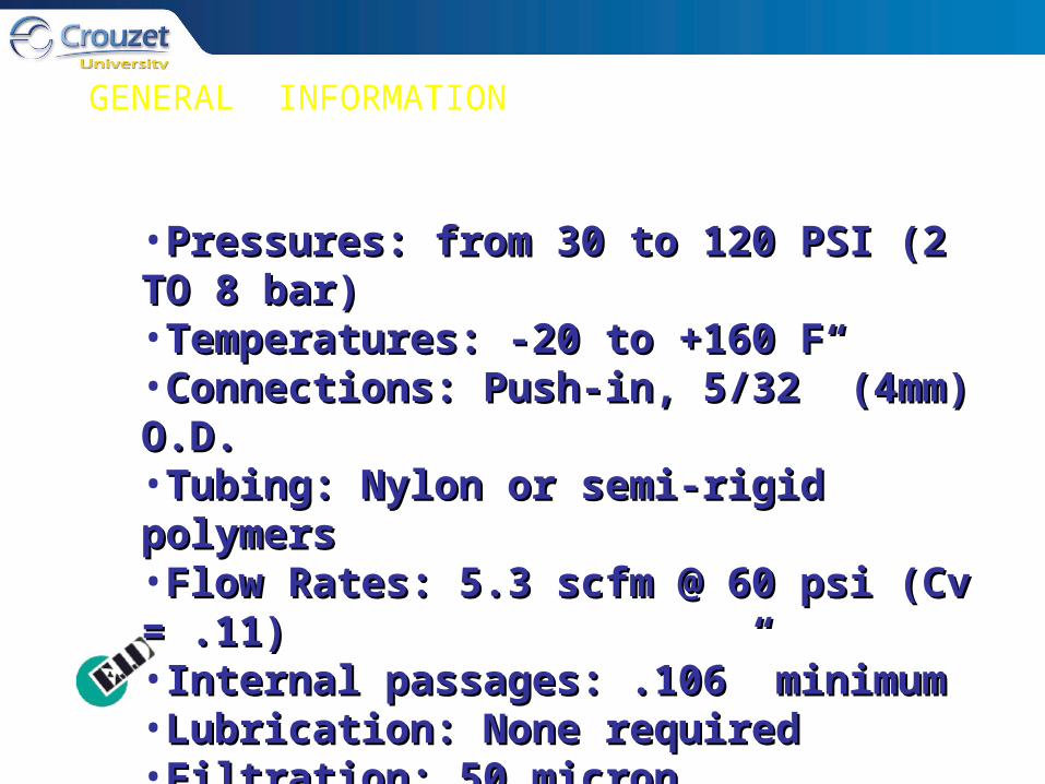
GENERAL INFORMATION
•Pressures: from 30 to 120 PSI (2 TO 8 bar)Pressures: from 30 to 120 PSI (2 TO 8 bar)•Temperatures: -20 to +160 FTemperatures: -20 to +160 F•Connections: Push-in, 5/32” (4mm) O.D.Connections: Push-in, 5/32” (4mm) O.D.•Tubing: Nylon or semi-rigid polymersTubing: Nylon or semi-rigid polymers•Flow Rates: 5.3 scfm @ 60 psi (Cv = .11)Flow Rates: 5.3 scfm @ 60 psi (Cv = .11)•Internal passages: .106” minimumInternal passages: .106” minimum•Lubrication: None requiredLubrication: None required•Filtration: 50 micron (recommended)Filtration: 50 micron (recommended)•Duty Cycle: Duty Cycle: 100 million actuations100 million actuations

בקרות לוגיות
הרכיבים העיקריים במערכות לוגיות הם:הרכיבים העיקריים במערכות לוגיות הם: OROR, , ANDAND, , YESYES ,, NOTNOT-כן, לא, או, ו-- כן, לא, או, ו -
כל רכיב כזה הוא שער לוגי שיכול להתחבר לשערים כל רכיב כזה הוא שער לוגי שיכול להתחבר לשערים נוספים כדי להרכיב מעגל בקרה על תנועה של מפעילים נוספים כדי להרכיב מעגל בקרה על תנועה של מפעילים
פניאומטיים.פניאומטיים.בכל רגע נתון מצב היציאה של רכיב לוגי כזה תלוי רק בכל רגע נתון מצב היציאה של רכיב לוגי כזה תלוי רק במצב הכניסות הלוגיות , אם יש כניסה או אין כניסה, במצב הכניסות הלוגיות , אם יש כניסה או אין כניסה, ואין תלות במצב הקודם של השער הלוגי או באיזשהו ואין תלות במצב הקודם של השער הלוגי או באיזשהו
אירוע מקרי.אירוע מקרי.
בקרות לוגיות )המשך(
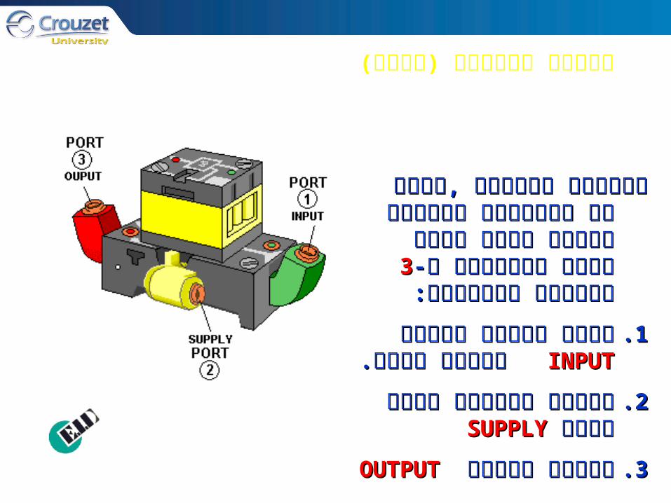
רכיבים לוגיים ,כאשר הם מחוברים רכיבים לוגיים ,כאשר הם מחוברים ליחידת הבסיס שלהם יהיו ליחידת הבסיס שלהם יהיו
כניסות כניסות 33תמיד מסומנים ב-תמיד מסומנים ב-::מסומנותמסומנות
INPUTINPUTמקבל סיגנל כניסה מקבל סיגנל כניסה 1.1.מרכיב קודם.מרכיב קודם.
חיבור לאספקת אויר דחוס חיבור לאספקת אויר דחוס 2.2.SUPPLYSUPPLY
OUTPUTOUTPUTסיגנל יציאה סיגנל יציאה 3.3.
בקרות לוגיות )המשך(
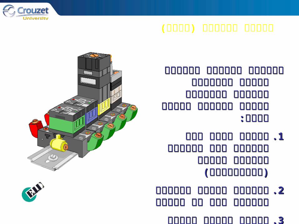
יחידות לוגיות יכולות להיות יחידות לוגיות יכולות להיות מחוברות בצורות מורכבות מחוברות בצורות מורכבות
בעזרת יחידות הבסיס שלהן:בעזרת יחידות הבסיס שלהן:
אספקת אויר אחת משותפת אספקת אויר אחת משותפת 1.1.כדי להקטין דרישות חיבור כדי להקטין דרישות חיבור
)אינסטלציה()אינסטלציה(
יחידות הבסיס ניתנות להתקנה יחידות הבסיס ניתנות להתקנה 2.2.קלה על מסילהקלה על מסילה
חיווי בדיקה עצמית קיים על חיווי בדיקה עצמית קיים על 3.3.יחידות הבסיסיחידות הבסיס
אלמנטים לוגיים
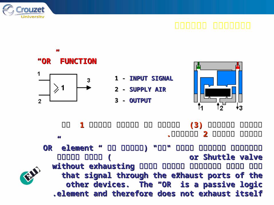
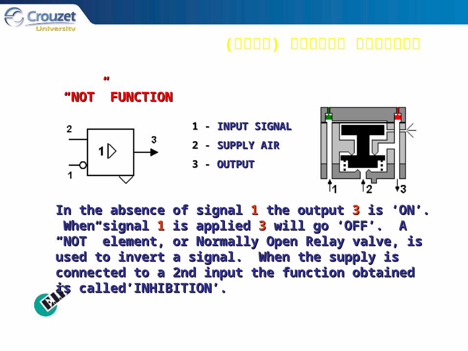
1 - 1 - INPUT SIGNALINPUT SIGNAL
2 - 2 - SUPPLY AIRSUPPLY AIR
3 - 3 - OUTPUTOUTPUT
““OR” FUNCTIONOR” FUNCTION
..נמצאיםנמצאים 22 או סיגנל כניסהאו סיגנל כניסה 11 יופיע אם סיגנל כניסהיופיע אם סיגנל כניסה ((33)) סיגנל היציאהסיגנל היציאה
OR” elementOR” element or or““משתמשים באלמנט לוגי "או" )שנקרא גם משתמשים באלמנט לוגי "או" )שנקרא גם Shuttle valveShuttle valve))כאשר לפחות אחד מכמה סיגנלים שונים נדרש כאשר לפחות אחד מכמה סיגנלים שונים נדרש without without
exhausting that signal through the exhaust ports of the exhausting that signal through the exhaust ports of the other devices. The “OR” is a passive logic element and other devices. The “OR” is a passive logic element and
therefore does not exhaust itselftherefore does not exhaust itself..
)המשך( אלמנטים לוגיים
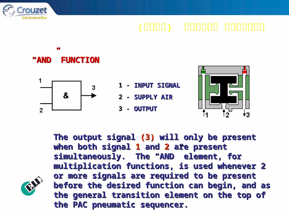
1 - 1 - INPUT SIGNALINPUT SIGNAL
2 - 2 - SUPPLY AIRSUPPLY AIR
3 - 3 - OUTPUT OUTPUT
““AND” FUNCTIONAND” FUNCTION
The output signal The output signal (3)(3) will only be present when both will only be present when both signal signal 11 and and 22 are present simultaneously. The “AND” are present simultaneously. The “AND” element, for multiplication functions, is used whenever 2 element, for multiplication functions, is used whenever 2 or more signals are required to be present before the or more signals are required to be present before the desired function can begin, and as the general transition desired function can begin, and as the general transition element on the top of the PAC pneumatic sequencer.element on the top of the PAC pneumatic sequencer.

אלמנטים לוגיים )המשך(
1 - 1 - INPUT SIGNALINPUT SIGNAL
2 - 2 - SUPPLY AIRSUPPLY AIR
3 - 3 - OUTPUTOUTPUT
The output signal The output signal (3)(3) is present if the signal is present if the signal 11 is present. A is present. A “YES” element, or Normally Closed Relay valve, is used as a “YES” element, or Normally Closed Relay valve, is used as a polarized “AND” element as a signal at port 1 will cause the polarized “AND” element as a signal at port 1 will cause the pressure to go from ports 2 to 3.pressure to go from ports 2 to 3.
““YES” FUNCTIONYES” FUNCTION
אלמנטים לוגיים )המשך(
1 - 1 - INPUT SIGNALINPUT SIGNAL
2 - 2 - SUPPLY AIRSUPPLY AIR
3 - 3 - OUTPUTOUTPUT
““NOT” FUNCTIONNOT” FUNCTION
In the absence of signal In the absence of signal 11 the output the output 33 is ‘ON’. When signal is ‘ON’. When signal 11 is applied is applied 33 will go ‘OFF’. A “NOT” element, or Normally will go ‘OFF’. A “NOT” element, or Normally Open Relay valve, is used to invert a signal. When the Open Relay valve, is used to invert a signal. When the supply is connected to a 2nd input the function obtained is supply is connected to a 2nd input the function obtained is called’INHIBITION’.called’INHIBITION’.

אלמנטים לוגיים )המשך(
1 - 1 - INPUT SIGNALINPUT SIGNAL
1 -1 - INPUT SIGNAL INPUT SIGNAL
2 - 2 - SUPPLY AIRSUPPLY AIR
3 - 3 - OUTPUT OUTPUT
3 -3 - OUTPUT OUTPUT
““MEMORY” FunctionMEMORY” Function
The appearance of signal The appearance of signal 11 causes the displacement of the causes the displacement of the spool, the output spool, the output 33 being put under pressure. This state is being put under pressure. This state is remembered until the arrival of a signal at port . The remembered until the arrival of a signal at port . The “MEMORY” element, or Flip-Flop, transforms a momentary “MEMORY” element, or Flip-Flop, transforms a momentary signal into a constant signal by shifting the slide from one signal into a constant signal by shifting the slide from one position to the other position. It will stay in the second position to the other position. It will stay in the second position until another pilot signal shifts the slide back to the position until another pilot signal shifts the slide back to the first position. first position.
LOGIC FUNCTIONS
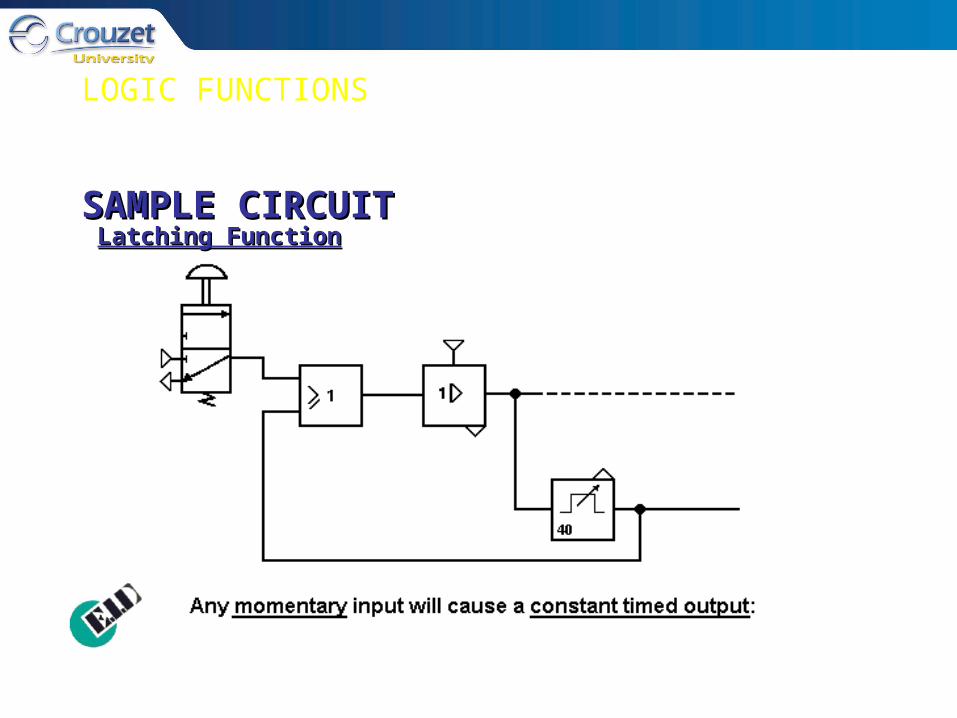
Latching FunctionLatching FunctionSAMPLE CIRCUITSAMPLE CIRCUIT
LOGIC FUNCTION
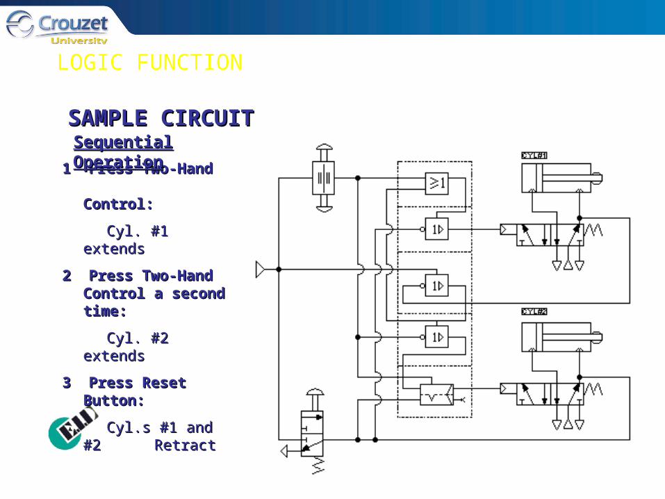
1 Press Two-Hand 1 Press Two-Hand Control: Control:
Cyl. #1 extendsCyl. #1 extends
2 Press Two-Hand 2 Press Two-Hand Control a second Control a second time:time:
Cyl. #2 extendsCyl. #2 extends
3 Press Reset Button:3 Press Reset Button:
Cyl.s #1 and #2 Cyl.s #1 and #2 RetractRetract
SAMPLE CIRCUITSAMPLE CIRCUITSequential OperationSequential Operation
LOGIC FUNCTION
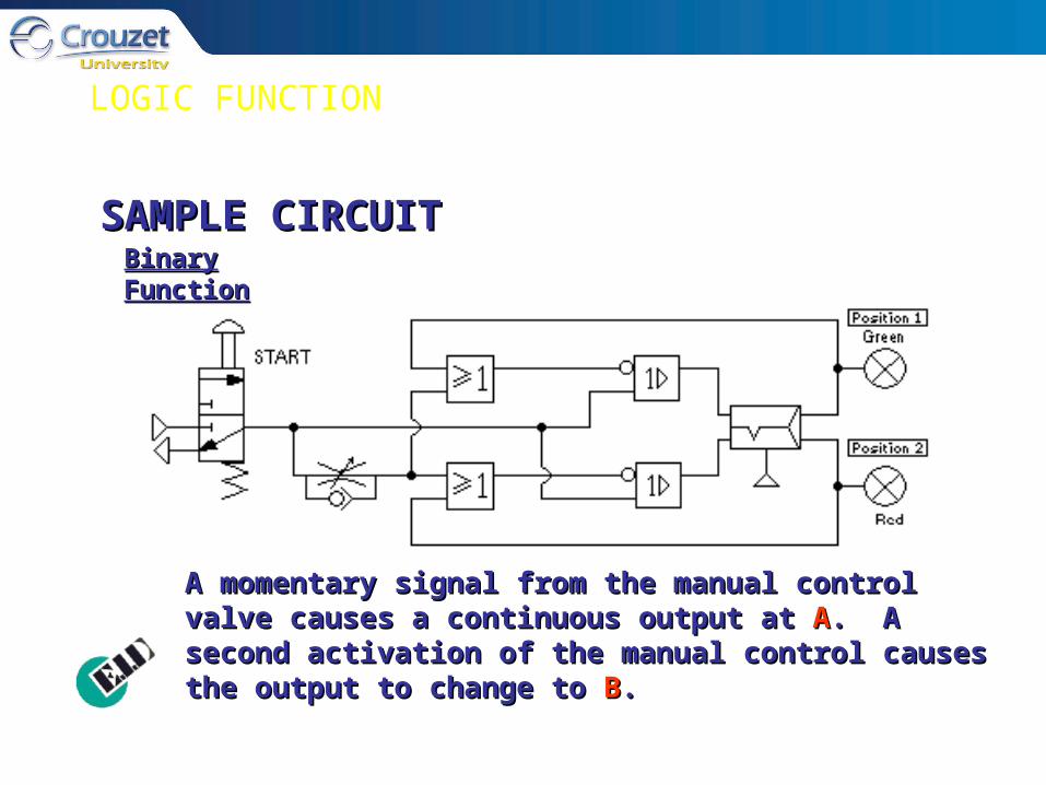
A momentary signal from the manual control valve causes A momentary signal from the manual control valve causes a continuous output at a continuous output at AA. A second activation of the . A second activation of the manual control causes the output to change to manual control causes the output to change to BB..
Binary FunctionBinary FunctionSAMPLE CIRCUITSAMPLE CIRCUIT

Pneumatics Specialist Course
Our solutions in pneumatic logic
(GB_autopneu.pdf)
Boolean algebra (page 51 to 55)
Exercises and hands-on (page 57 to 65)

PROGRAMMABLE AIR CONTROLLERS
The programmable air controllers (P.A.C.) are The programmable air controllers (P.A.C.) are modules of logic components specialized for modules of logic components specialized for sequential operation of pneumatic devices. Each sequential operation of pneumatic devices. Each P.A.C. module controls one step in a sequence. P.A.C. module controls one step in a sequence. Position indicating sensors confirm that the Position indicating sensors confirm that the operation has been completed and advance to the operation has been completed and advance to the next P.A.C. module. Programming is accomplished next P.A.C. module. Programming is accomplished by arranging the necessary sequencing steps in by arranging the necessary sequencing steps in progressive order and supplying sensors to confirm progressive order and supplying sensors to confirm each step.each step.

PROGRAMMABLE AIR CONTROLLERS
When initiated, the When initiated, the modules emit a output modules emit a output and wait for confirmation and wait for confirmation that the action has taken that the action has taken place. Upon receipt of the place. Upon receipt of the confirmation they ‘step-confirmation they ‘step-on’ to the next module in on’ to the next module in the succession. Each the succession. Each module performs a similar module performs a similar operation until the entire operation until the entire sequence is completed.sequence is completed.

PROGRAMMABLE AIR CONTROLLERS
The pneumatic sequencer is used in any pneumatic The pneumatic sequencer is used in any pneumatic circuit that requires step-by-step operation and circuit that requires step-by-step operation and feedback signals after each step to ensure safe feedback signals after each step to ensure safe operation.operation.

P.A.C. MODULES
MODULE 2
START SIGNAL (Momentary Input)START SIGNAL (Momentary Input) OUTPUT AT PORT 3 OUTPUT AT PORT 3 (CONTINUOUS)(CONTINUOUS)SIGNAL FROM SENSOR (Port 1)SIGNAL FROM SENSOR (Port 1) STEP FORWARD TO MODULE 2STEP FORWARD TO MODULE 2
INPUT FROM MODULE 1 INPUT FROM MODULE 1 (Momentary)(Momentary) OUTPUT AT PORT 3 OUTPUT AT PORT 3 (CONTINUOUS)(CONTINUOUS)
SIGNAL FROM SENSOR (PORT 1)SIGNAL FROM SENSOR (PORT 1) OUTPUT AT PORT 6OUTPUT AT PORT 6INPUT AT PORT 7 INPUT AT PORT 7 RESETS MODULES 2 AND 1 TO RESETS MODULES 2 AND 1 TO 00
SEQUENCE REPEATS IF START SEQUENCE REPEATS IF START SIGNAL AT PORT 4 IS STILL PRESENTSIGNAL AT PORT 4 IS STILL PRESENT
MODULE 1

P.A.C. MODULES
SAMPLE SEQUENCESAMPLE SEQUENCE
P.A.C. MODULES
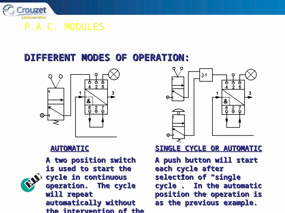
DIFFERENT MODES OF OPERATION:DIFFERENT MODES OF OPERATION:
AUTOMATICAUTOMATIC SINGLE CYCLE OR AUTOMATICSINGLE CYCLE OR AUTOMATIC
A two position switch is A two position switch is used to start the cycle in used to start the cycle in continuous operation. The continuous operation. The cycle will repeat cycle will repeat automatically without the automatically without the intervention of the operator.intervention of the operator.
A push button will start each A push button will start each cycle after selection of “single cycle after selection of “single cycle”. In the automatic cycle”. In the automatic position the operation is as the position the operation is as the previous example.previous example.
P.A.C. MODULES
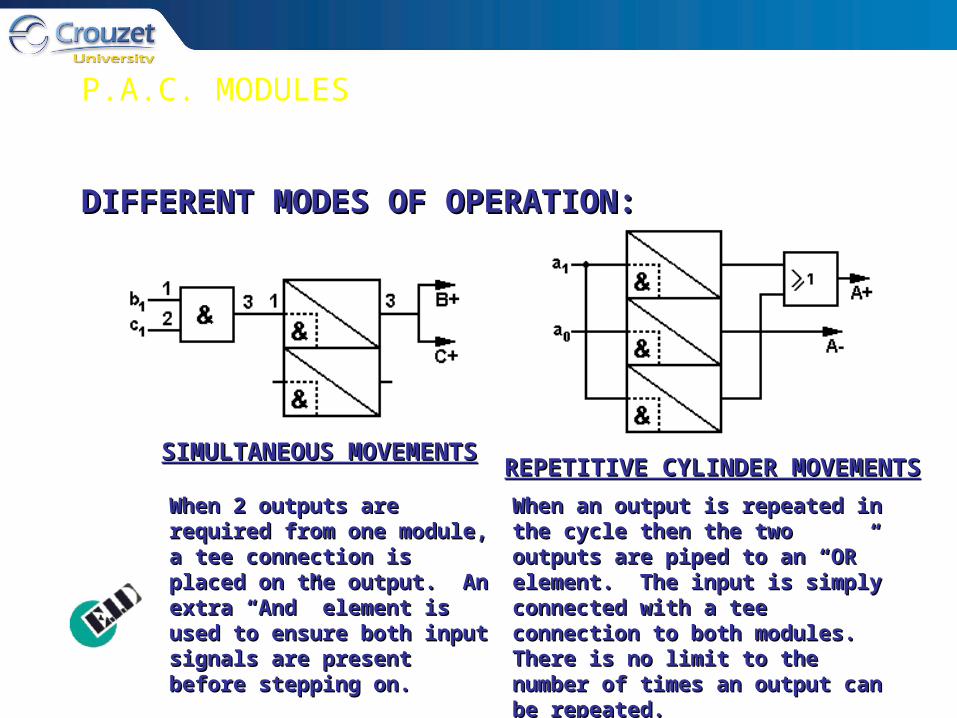
DIFFERENT MODES OF OPERATION:DIFFERENT MODES OF OPERATION:
SIMULTANEOUS SIMULTANEOUS MOVEMENTSMOVEMENTS REPETITIVE CYLINDER MOVEMENTSREPETITIVE CYLINDER MOVEMENTS
When 2 outputs are required When 2 outputs are required from one module, a tee from one module, a tee connection is placed on the connection is placed on the output. An extra “And” element output. An extra “And” element is used to ensure both input is used to ensure both input signals are present before signals are present before stepping on.stepping on.
When an output is repeated in the When an output is repeated in the cycle then the two outputs are piped cycle then the two outputs are piped to an “OR” element. The input is to an “OR” element. The input is simply connected with a tee simply connected with a tee connection to both modules. There connection to both modules. There is no limit to the number of times an is no limit to the number of times an output can be repeated.output can be repeated.

P.A.C. MODULES
DIFFERENT MODES OF OPERATION:DIFFERENT MODES OF OPERATION:
TIMER FUNCTIONTIMER FUNCTION BLEED SENSORBLEED SENSORThe time delay will be The time delay will be started by the input a . A started by the input a . A delay will occur before delay will occur before stepping on to the next stepping on to the next step.step.
When the sequence module is When the sequence module is switched on a low pressure bleed switched on a low pressure bleed is delivered out of port 1. When is delivered out of port 1. When the bleed is blocked by the the bleed is blocked by the cylinder the relay switches and cylinder the relay switches and the sequencer steps on.the sequencer steps on.
The function of each sequence module can be changed by replacing the “And” element which is screwed to the top of the sequence module, with other logic elements.
P.A.C. MODULES
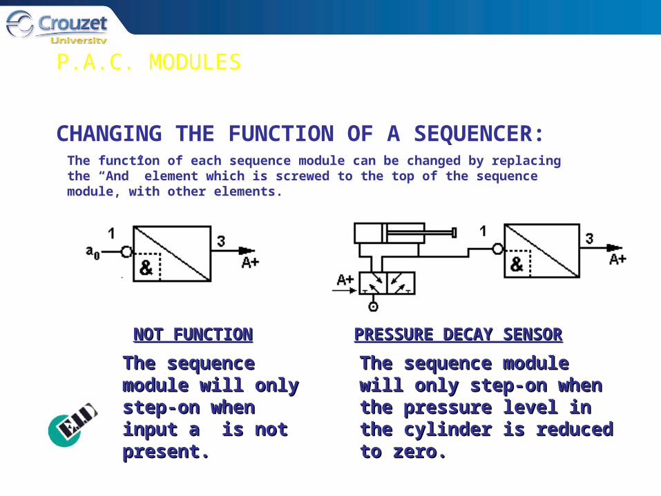
CHANGING THE FUNCTION OF A SEQUENCER:
NOT FUNCTIONNOT FUNCTION PRESSURE DECAY SENSORPRESSURE DECAY SENSOR
The sequence The sequence module will only module will only step-on when input step-on when input a is not present.a is not present.
The sequence module will The sequence module will only step-on when the only step-on when the pressure level in the cylinder pressure level in the cylinder is reduced to zero.is reduced to zero.
The function of each sequence module can be changed by replacing the “And” element which is screwed to the top of the sequence module, with other elements.
P.A.C. MODULES
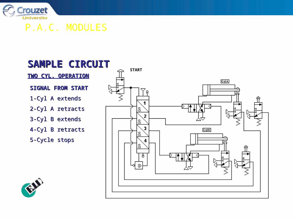
SIGNAL FROM START SIGNAL FROM START
1-Cyl A extends1-Cyl A extends
2-Cyl A retracts2-Cyl A retracts
3-Cyl B extends3-Cyl B extends
4-Cyl B retracts4-Cyl B retracts
5-Cycle stops5-Cycle stops
SAMPLE CIRCUITSAMPLE CIRCUITTWO CYL. OPERATIONTWO CYL. OPERATION
STARTSTART

P.A.C. MODULES
SAMPLE CIRCUITSAMPLE CIRCUIT
SIGNAL FROM STARTSIGNAL FROM START
1-Cyl A extends1-Cyl A extends
2-Cyl A retracts2-Cyl A retracts
3-Cyl B extends3-Cyl B extends
4-Cyl B retracts4-Cyl B retracts
CYCLE REPEATSCYCLE REPEATS
E-STOP ACTUATEDE-STOP ACTUATED
1-Cycle stops immediately1-Cycle stops immediately
2-All cylinders retract2-All cylinders retract
3-System resets to first 3-System resets to first positionposition
E-STOP FUNCTIONE-STOP FUNCTION
E-STOPOFF
START
Off
Start
E-stop
P.A.C. MODULES
SAMPLE CIRCUITSAMPLE CIRCUIT
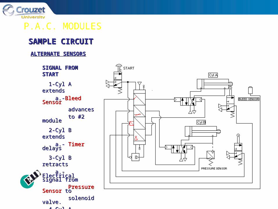
ALTERNATE SENSORSALTERNATE SENSORS
SIGNAL FROM SIGNAL FROM STARTSTART
1-Cyl A extends1-Cyl A extends
a.-a.-Bleed SensorBleed Sensor advancesadvances to #2 moduleto #2 module
2-Cyl B extends2-Cyl B extends
a.- a.- Timer Timer delaysdelays
3-Cyl B retracts3-Cyl B retracts
a.-Electrical signal a.-Electrical signal fromfrom Pressure SensorPressure Sensor toto solenoid valve.solenoid valve. 4-Cyl A retracts4-Cyl A retracts
5-Cycle stops5-Cycle stops

POSITION DETECTORS
Position detectors are pneumatic limit switches. Position detectors are pneumatic limit switches. They detect the physical presence of an object and They detect the physical presence of an object and send a pneumatic signal. Most control systems send a pneumatic signal. Most control systems depend on feedback from position detectors/sensors depend on feedback from position detectors/sensors to confirm completion of a previous action before to confirm completion of a previous action before proceeding with further sequencing. proceeding with further sequencing.
A number of specialized contacts (pictured here) may be adapted to A number of specialized contacts (pictured here) may be adapted to the valves to make them better suited for their operations.the valves to make them better suited for their operations.
Position Detector
DETECTORS

POSITION DETECTORS (CONTINUED)
Gap Sensor
Bleed Sensor Relay
Another type of position detector requires no Another type of position detector requires no physical contact to detect an object. The gap physical contact to detect an object. The gap sensors and proximity detectors emit a small sensors and proximity detectors emit a small bleed of air and detect any interruption of this bleed of air and detect any interruption of this stream. When coupled with very sensitive stream. When coupled with very sensitive sensor relays or amplifiers they too can report sensor relays or amplifiers they too can report on the presence of objects and send a on the presence of objects and send a confirming signal to the control system. confirming signal to the control system. Position Detectors are required in most Position Detectors are required in most applications of programmable air controllers.applications of programmable air controllers.
PROXIMITY SENSOR TYPE:PROXIMITY SENSOR TYPE:
POSITION DETECTORS

TIMER RELAYS
Timer relays are used to delay the appearance or Timer relays are used to delay the appearance or disappearance of an output signal in relation to the disappearance of an output signal in relation to the appearance of the input signal.appearance of the input signal.
The operating principal entails the filling of a reservoir via a The operating principal entails the filling of a reservoir via a flow restrictor until the threshold pressure of the relay (NC flow restrictor until the threshold pressure of the relay (NC or NO) is reached. The non-return device enables the or NO) is reached. The non-return device enables the capacity to be drained quickly, resetting the time delay. capacity to be drained quickly, resetting the time delay. Flow restrictors may be ether fixed (.4 sec) or adjustable (15 Flow restrictors may be ether fixed (.4 sec) or adjustable (15 and 30 sec available). ‘Delay on’ and ‘delay off’ styles are and 30 sec available). ‘Delay on’ and ‘delay off’ styles are available. available.
TIMERS:TIMERS:
TIMER RELAYS (CONTINUED)
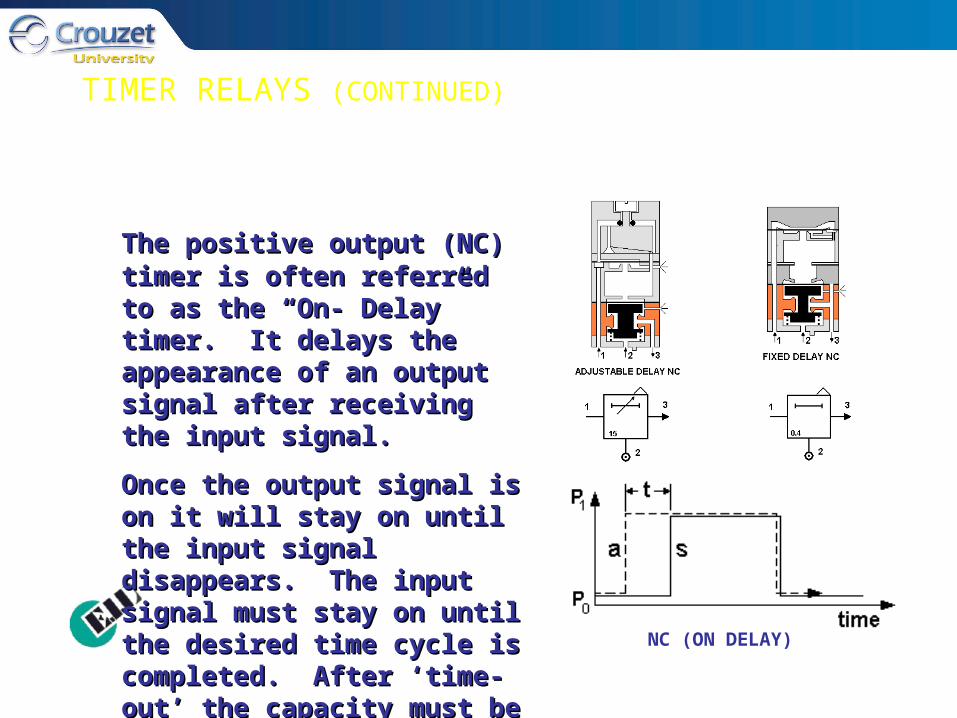
NC (ON DELAY)
The positive output (NC)The positive output (NC) timer timer is often referred to as the “On- is often referred to as the “On- Delay” timer. It delays the Delay” timer. It delays the appearance of an output signal appearance of an output signal after receiving the input signal.after receiving the input signal.
Once the output signal is on it Once the output signal is on it will stay on until the input signal will stay on until the input signal disappears. The input signal disappears. The input signal must stay on until the desired must stay on until the desired time cycle is completed. After time cycle is completed. After ‘time-out’ the capacity must be ‘time-out’ the capacity must be drained to re-set the time delay.drained to re-set the time delay.
TIMER RELAYS (CONTINUED)
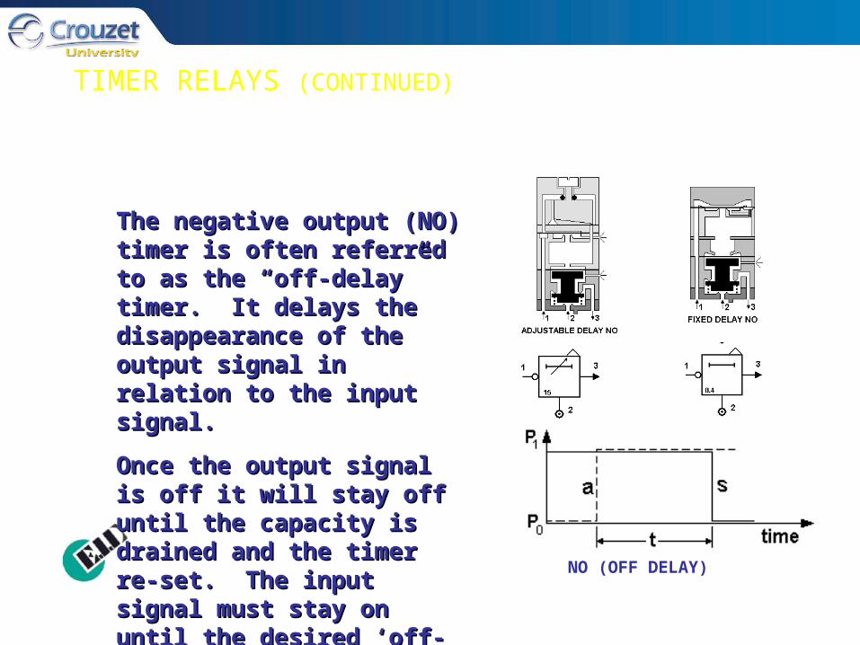
NO (OFF DELAY)
The negative output (NO) The negative output (NO) timer is often referred to as timer is often referred to as the “off-delay” timer. It delays the “off-delay” timer. It delays the disappearance of the the disappearance of the output signal in relation to the output signal in relation to the input signal.input signal.
Once the output signal is off it Once the output signal is off it will stay off until the capacity will stay off until the capacity is drained and the timer re-set. is drained and the timer re-set. The input signal must stay on The input signal must stay on until the desired ‘off-time’ has until the desired ‘off-time’ has elapsed.elapsed.
IMPULSE GENERATOR
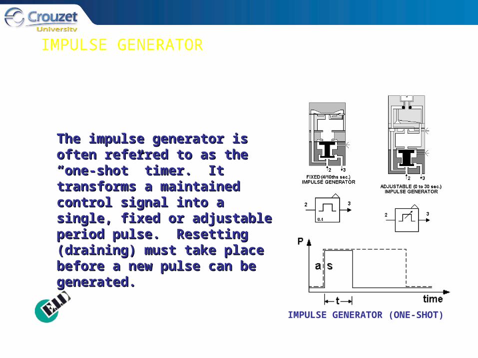
The impulse generator is often The impulse generator is often referred to as the “one-shot” referred to as the “one-shot” timer. It transforms a maintained timer. It transforms a maintained control signal into a single, fixed control signal into a single, fixed or adjustable period pulse. or adjustable period pulse. Resetting (draining) must take Resetting (draining) must take place before a new pulse can be place before a new pulse can be generated.generated.
IMPULSE GENERATOR (ONE-SHOT)

FREQUENCY GENERATOR
The frequency generator transforms a The frequency generator transforms a maintained signal into pulses at maintained signal into pulses at adjustable frequencies. Work time of a adjustable frequencies. Work time of a pulse period is always 1/3rd of the total pulse period is always 1/3rd of the total period duration, 1/3rd on, 2/3rd off.period duration, 1/3rd on, 2/3rd off.
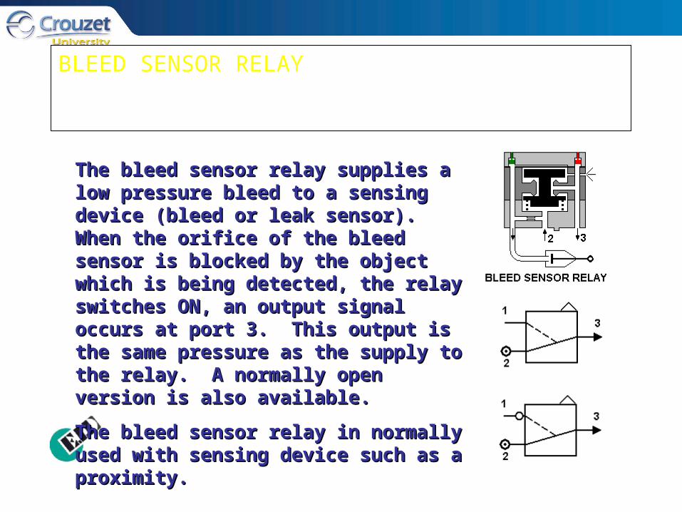
BLEED SENSOR RELAY
The bleed sensor relay supplies a low The bleed sensor relay supplies a low pressure bleed to a sensing device (bleed pressure bleed to a sensing device (bleed or leak sensor). When the orifice of the or leak sensor). When the orifice of the bleed sensor is blocked by the object bleed sensor is blocked by the object which is being detected, the relay switches which is being detected, the relay switches ON, an output signal occurs at port 3. This ON, an output signal occurs at port 3. This output is the same pressure as the supply output is the same pressure as the supply to the relay. A normally open version is to the relay. A normally open version is also available.also available.
The bleed sensor relay in normally used The bleed sensor relay in normally used with sensing device such as a proximity.with sensing device such as a proximity.

AMPLIFIER RELAY
The amplifier relay enables a high The amplifier relay enables a high pressure output signal to be obtained pressure output signal to be obtained from a low pressure input signal. It is from a low pressure input signal. It is frequently used in conjunction with frequently used in conjunction with pneumatic gap sensors type of proximity pneumatic gap sensors type of proximity sensors and is available in NC and NO sensors and is available in NC and NO versions.versions.
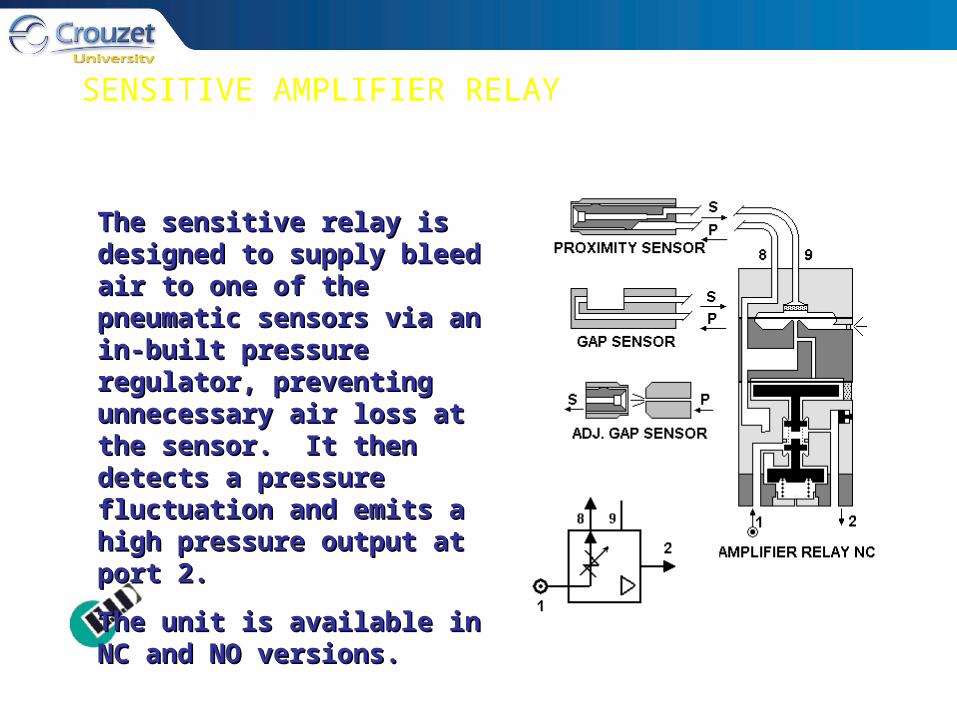
SENSITIVE AMPLIFIER RELAY
The sensitive relay is designed to The sensitive relay is designed to supply bleed air to one of the supply bleed air to one of the pneumatic sensors via an in-built pneumatic sensors via an in-built pressure regulator, preventing pressure regulator, preventing unnecessary air loss at the unnecessary air loss at the sensor. It then detects a sensor. It then detects a pressure fluctuation and emits a pressure fluctuation and emits a high pressure output at port 2. high pressure output at port 2.
The unit is available in NC and The unit is available in NC and NO versions.NO versions.

ADJUSTABLE PRESSURE SENSOR
Adjustable pressure sensors (manostats) Adjustable pressure sensors (manostats) switch the output when the input signal switch the output when the input signal reaches a predetermined and pre-adjusted reaches a predetermined and pre-adjusted pressure level.pressure level.
NC and NO versions are available.NC and NO versions are available.
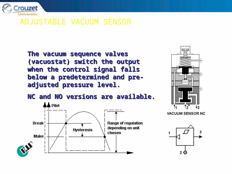
ADJUSTABLE VACUUM SENSOR
The vacuum sequence valves (vacuostat) The vacuum sequence valves (vacuostat) switch the output when the control signal switch the output when the control signal falls below a predetermined and pre-falls below a predetermined and pre-adjusted pressure level.adjusted pressure level.
NC and NO versions are available.NC and NO versions are available.
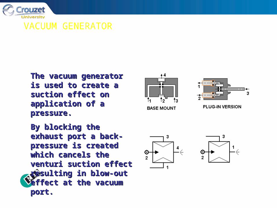
VACUUM GENERATOR
The vacuum generator is The vacuum generator is used to create a suction used to create a suction effect on application of a effect on application of a pressure. pressure.
By blocking the exhaust By blocking the exhaust port a back-pressure is port a back-pressure is created which cancels the created which cancels the venturi suction effect venturi suction effect resulting in blow-out effect resulting in blow-out effect at the vacuum port.at the vacuum port.

TWO-HAND SAFETY MODULE
The two-hand safety module is used The two-hand safety module is used to ensure operator safety during a to ensure operator safety during a dangerous machine movement, dangerous machine movement, cycle or phase. To obtain an output cycle or phase. To obtain an output signal it is necessary to give two signal it is necessary to give two simultaneous input signals (1 & 2) simultaneous input signals (1 & 2) with a maximum delay of 0.4s. The with a maximum delay of 0.4s. The output is only maintained if the 2 output is only maintained if the 2 input signals are present. It cannot input signals are present. It cannot reappear until both buttons have reappear until both buttons have been released and re-operated.been released and re-operated.

SUB BASES
Each category, or style, of control components has a Each category, or style, of control components has a specially designed sub base for component mounting, specially designed sub base for component mounting, tubing connections and common air supply. Internal tubing connections and common air supply. Internal passages in the sub bases connect to the proper passages passages in the sub bases connect to the proper passages on the control component. Provisions are made to connect on the control component. Provisions are made to connect sub bases to each other, when required, to form manifolds sub bases to each other, when required, to form manifolds of components. The manifolds, when properly arranged, of components. The manifolds, when properly arranged, form pneumatic circuits capable of control functions.form pneumatic circuits capable of control functions.
Additionally, the sub bases provide a diagnostic function Additionally, the sub bases provide a diagnostic function by indicating the progression of pneumatic signals through by indicating the progression of pneumatic signals through a given circuit. “Pop-up” indicators progressively follow a given circuit. “Pop-up” indicators progressively follow the movement of the signal with visual confirmations.the movement of the signal with visual confirmations.
SUB BASES (CONTINUED)
FOR LOGIC & RELAYSFOR LOGIC & RELAYS
These sub bases provide mounting for all logic and related These sub bases provide mounting for all logic and related relays such as timers and pressure switches. Available in relays such as timers and pressure switches. Available in singular or associable styles, they can mount components singular or associable styles, they can mount components individually or in multiples. Push-in connectors for 5/32” individually or in multiples. Push-in connectors for 5/32” semi-rigid tubing are provided. semi-rigid tubing are provided.
When used for multiple mountings the associable style can When used for multiple mountings the associable style can transform it’s internal passages to connect ports 3 to 2 or transform it’s internal passages to connect ports 3 to 2 or ports 2 to 2. A manual “selector” is provided for this ports 2 to 2. A manual “selector” is provided for this purpose. (See illustration on next slide)purpose. (See illustration on next slide)
‘‘Pop-up’ diagnostic indicators are provided at ports 1 & 3.Pop-up’ diagnostic indicators are provided at ports 1 & 3.
Ports are numbered and color coded for convenience.Ports are numbered and color coded for convenience.
LOGIC SUB BASES
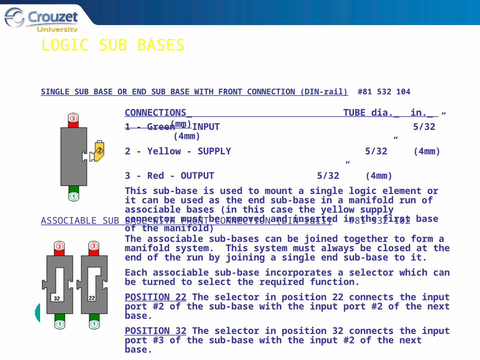
SINGLE SUB BASE OR END SUB BASE WITH FRONT CONNECTION (DIN-rail) #81 532 104
ASSOCIABLE SUB BASE WITH FRONT CONNECTION (DIN-rail) #81 532 102
CONNECTIONS_ TUBE dia._ in._ _(mm)
1 - Green - INPUT 5/32” (4mm)
2 - Yellow - SUPPLY 5/32” (4mm)
3 - Red - OUTPUT 5/32” (4mm)
This sub-base is used to mount a single logic element or it can be used as the end sub-base in a manifold run of associable bases (in this case the yellow supply connector must be removed and inserted in the first base of the manifold)
The associable sub-bases can be joined together to form a manifold system. This system must always be closed at the end of the run by joining a single end sub-base to it.
Each associable sub-base incorporates a selector which can be turned to select the required function.
POSITION 22 The selector in position 22 connects the input port #2 of the sub-base with the input port #2 of the next base.
POSITION 32 The selector in position 32 connects the input port #3 of the sub-base with the input #2 of the next base.

LOGIC SUB BASES (continued)
1. Input port (green - port 1)1. Input port (green - port 1)
2. Output port (red - port 3)2. Output port (red - port 3)
3. Supply port (yellow - port 2)3. Supply port (yellow - port 2)
4. Input port integral to 4. Input port integral to
sub basesub base
5. Input indicator (green)5. Input indicator (green)
6. Output indicator (red)6. Output indicator (red)
7. 1/4 turn screws7. 1/4 turn screws
8. Marking tag8. Marking tag
9. Flow direction arrow9. Flow direction arrow
10. Mounting tongue10. Mounting tongue
11. Mounting groove11. Mounting groove
12. Selector12. Selector

SUB BASES (CONTINUED)
FOR PAC MODULESFOR PAC MODULES
Sub bases for mounting PAC modules enable multiple units to Sub bases for mounting PAC modules enable multiple units to be arranged in tandem for sequential operations. Separate be arranged in tandem for sequential operations. Separate ‘end base pairs’ allow for connections of common air supply, ‘end base pairs’ allow for connections of common air supply, start signal input and ‘loop’ for continuous operation. Push-in start signal input and ‘loop’ for continuous operation. Push-in connectors for 5/32” semi-rigid tubing are provided. connectors for 5/32” semi-rigid tubing are provided.
‘‘Pop-up’ diagnostic indicators are located at all critical points Pop-up’ diagnostic indicators are located at all critical points to confirm presence of both input and output signals. Ports to confirm presence of both input and output signals. Ports are numbered and color coded for convenience.are numbered and color coded for convenience.
Two mounting styles, one for 35mm din. rail, one for panel Two mounting styles, one for 35mm din. rail, one for panel mounting, are available.mounting, are available.
SUB BASES (CONTINUED)

P.A.C. SUB BASES (continued)
INTERIM SUB-BASE WITH FRONT CONNECTION (DIN rail) #81 551 101
END BASE-1 PAIR ENTRY & EXIT- WITH FRONT CONNECTION #81 552 101
CONNECTIONS_____________TUBE dia._ in._ _(mm)
1 - Green - INPUT 5/32” (4mm)
3 - Red - OUTPUT 5/32” (4mm)
CONNECTIONS_______________TUBE dia._ in._ _(mm)
4 & 7 - Green - INPUT (Start & Reset) 5/32” (4mm)
2 - Yellow - SUPPLY 1/4” (6.35 mm)
5 & 6 - Red - OUTPUT (In-cycle & Reset) 5/32” (4mm)
Interim bases, each mounting a single PAC module, are mounted in tandem to perform successive ‘stepping’ operations. These bases are equipped with attaching tabs and self-sealing ports to form manifolds of interconnected air passages.
End base pairs cap the ends of interim bases and provide service connections. Attaching tabs and self-sealing ports are compatible with the interim bases. End bases do not mount PAC modules.
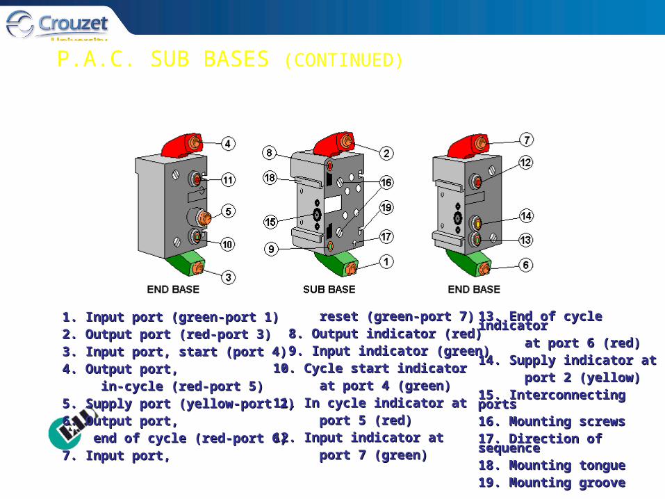
1. Input port (green-port 1)1. Input port (green-port 1)2. Output port (red-port 3)2. Output port (red-port 3)3. Input port, start (port 4)3. Input port, start (port 4)4. Output port, 4. Output port, in-cycle (red-port 5)in-cycle (red-port 5)5. Supply port (yellow-port 2)5. Supply port (yellow-port 2)6. Output port, 6. Output port, end of cycle (red-port 6)end of cycle (red-port 6)7. Input port, 7. Input port,
reset (green-port 7)reset (green-port 7) 8. Output indicator (red)8. Output indicator (red) 9. Input indicator (green)9. Input indicator (green)10. Cycle start indicator10. Cycle start indicator at port 4 (green)at port 4 (green)11. In cycle indicator at 11. In cycle indicator at port 5 (red)port 5 (red)12. Input indicator at 12. Input indicator at port 7 (green)port 7 (green)
13. End of cycle indicator13. End of cycle indicator at port 6 (red)at port 6 (red)14. Supply indicator at 14. Supply indicator at port 2 (yellow)port 2 (yellow)15. Interconnecting ports15. Interconnecting ports16. Mounting screws16. Mounting screws17. Direction of sequence 17. Direction of sequence 18. Mounting tongue18. Mounting tongue19. Mounting groove19. Mounting groove
P.A.C. SUB BASES (CONTINUED)
TROUBLESHOOTING
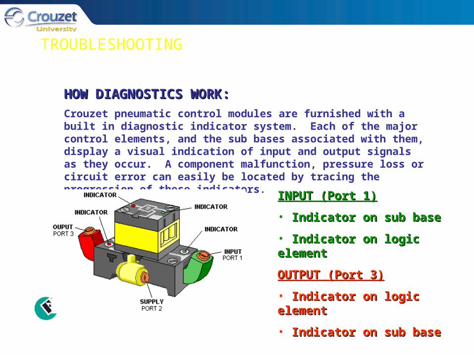
HOW DIAGNOSTICS WORK:HOW DIAGNOSTICS WORK:
Crouzet pneumatic control modules are furnished with a built in diagnostic indicator system. Each of the major control elements, and the sub bases associated with them, display a visual indication of input and output signals as they occur. A component malfunction, pressure loss or circuit error can easily be located by tracing the progression of these indicators.
INPUT (Port 1)INPUT (Port 1)
• Indicator on sub baseIndicator on sub base
• Indicator on logic elementIndicator on logic element
OUTPUT (Port 3)OUTPUT (Port 3)
• Indicator on logic elementIndicator on logic element
• Indicator on sub baseIndicator on sub base
TROUBLESHOOTING (CONTINUED)
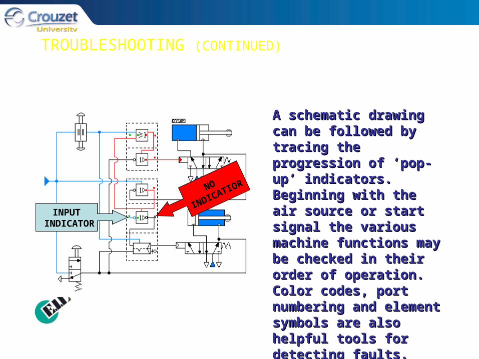
A schematic drawing can A schematic drawing can be followed by tracing the be followed by tracing the progression of ‘pop-up’ progression of ‘pop-up’ indicators. Beginning with indicators. Beginning with the air source or start the air source or start signal the various machine signal the various machine functions may be checked functions may be checked in their order of operation. in their order of operation. Color codes, port Color codes, port numbering and element numbering and element symbols are also helpful symbols are also helpful tools for detecting faults.tools for detecting faults.
INPUT INDICATOR
NO
INDICATIOR
TROUBLESHOOTING (CONTINUED)
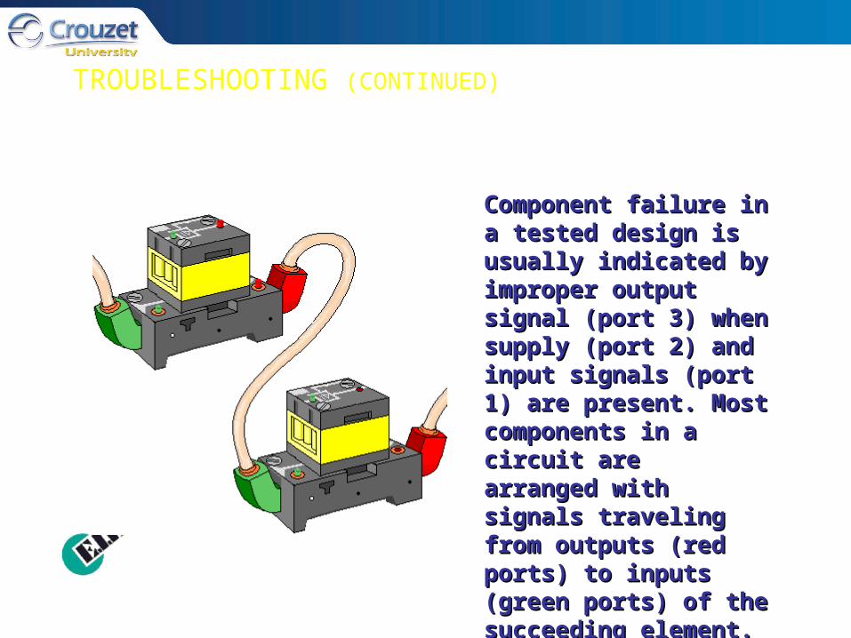
Component failure in a Component failure in a tested design is usually tested design is usually indicated by improper indicated by improper output signal (port 3) output signal (port 3) when supply (port 2) and when supply (port 2) and input signals (port 1) are input signals (port 1) are present. Most present. Most components in a circuit components in a circuit are arranged with signals are arranged with signals traveling from outputs traveling from outputs (red ports) to inputs (red ports) to inputs (green ports) of the (green ports) of the succeeding element. succeeding element.

TROUBLESHOOTING (CONTINUED)
When a fault is suspected When a fault is suspected the element should be the element should be identified by its symbol and identified by its symbol and it’s function determined. it’s function determined. With this information the With this information the diagnostic indicators are diagnostic indicators are again useful in actual again useful in actual testing. By duplicating the testing. By duplicating the proper combination of input proper combination of input and supply signals the and supply signals the binary output for that binary output for that particular component will particular component will be evident by the ‘pop-up’ be evident by the ‘pop-up’ indication.indication.

DIRECTIONAL VALVES
Directional valves or “power valves”, Directional valves or “power valves”, are used to operate larger sized are used to operate larger sized actuators such as cylinders or rotary actuators such as cylinders or rotary devices when higher air volumes are devices when higher air volumes are required. required.
1. Size of the valve is determined by 1. Size of the valve is determined by the volume required. the volume required.
2. They may be pilot operated by 2. They may be pilot operated by solenoid or air signals from control solenoid or air signals from control devices. devices.

DIRECTIONAL VALVES (CONTINUED)
Directional valves receive signals from a control device and direct power Directional valves receive signals from a control device and direct power to the actuators. They may also provide an exhaust function while at to the actuators. They may also provide an exhaust function while at rest. Function of the valves must be matched to the purpose of the rest. Function of the valves must be matched to the purpose of the actuator and the job to be performed.actuator and the job to be performed.

DIRECTIONAL VALVES (CONTINUED)
The 5/2 Directional Valve provides power to the actuator and an exhaust function The 5/2 Directional Valve provides power to the actuator and an exhaust function as it alternates between positions.as it alternates between positions. Flow ratings for the directional valve must be Flow ratings for the directional valve must be chosen to accommodate the size and desired speed of the actuator.chosen to accommodate the size and desired speed of the actuator.

DIRECTIONAL VALVES (CONTINUED)
IDENTIFICATION OF PORTSIDENTIFICATION OF PORTS 11 = pressure inlet port= pressure inlet port
2 and 4 = actuator ports2 and 4 = actuator ports
3 and 5 = exhaust ports3 and 5 = exhaust ports
1414 = piloting, control function = piloting, control function [connecting pressure [connecting pressure port (1) port (1) with with
actuator port (4)]actuator port (4)]
1212 = piloting, return function = piloting, return function [connecting pressure [connecting pressure
port (1) port (1) with with
actuator port (2)]actuator port (2)]
DIRECTIONAL VALVES (CONTINUED)
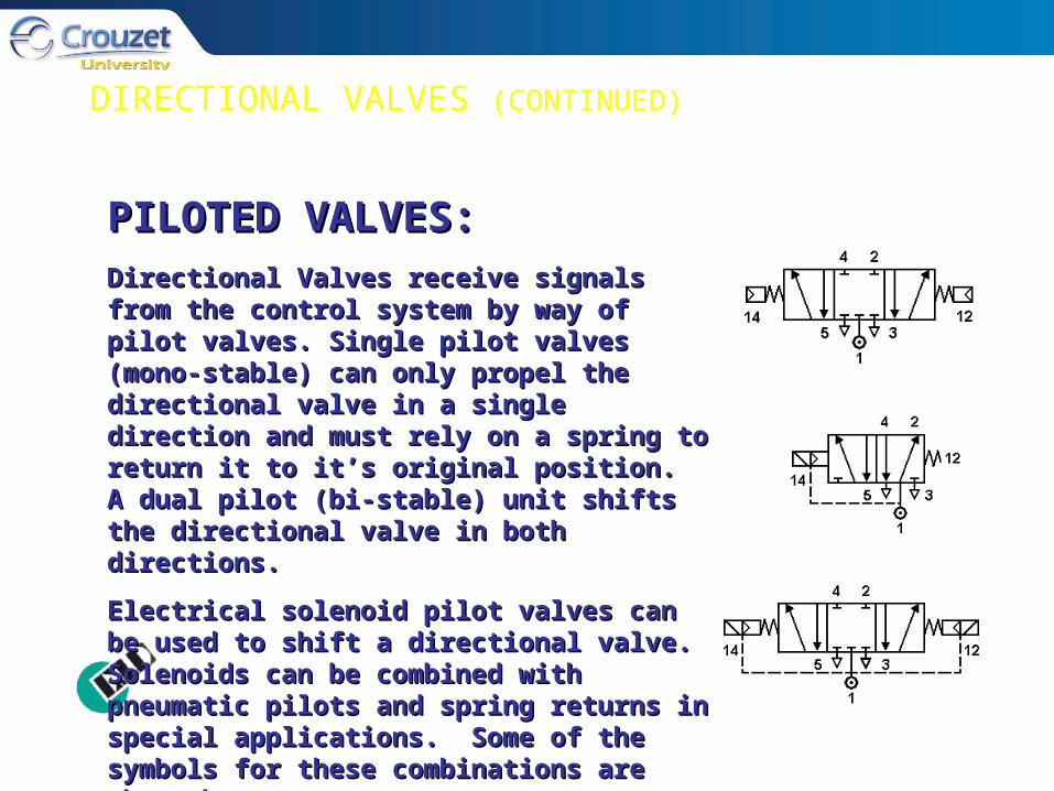
PILOTED VALVES:PILOTED VALVES:Directional Valves receive signals from the Directional Valves receive signals from the control system by way of pilot valves. Single control system by way of pilot valves. Single pilot valves (mono-stable) can only propel the pilot valves (mono-stable) can only propel the directional valve in a single direction and must directional valve in a single direction and must rely on a spring to return it to it’s original rely on a spring to return it to it’s original position. A dual pilot (bi-stable) unit shifts the position. A dual pilot (bi-stable) unit shifts the directional valve in both directions. directional valve in both directions.
Electrical solenoid pilot valves can be used to Electrical solenoid pilot valves can be used to shift a directional valve. Solenoids can be shift a directional valve. Solenoids can be combined with pneumatic pilots and spring combined with pneumatic pilots and spring returns in special applications. Some of the returns in special applications. Some of the symbols for these combinations are shown symbols for these combinations are shown here.here.
CONSTRUCTION MATERIALS
• Poppet - DesmopanPoppet - Desmopan• Rings And Diaphragm - NitrileRings And Diaphragm - Nitrile• Indicators - Hytrel (Elastomer)Indicators - Hytrel (Elastomer)• Component Body - Delrin ( Pom)Component Body - Delrin ( Pom)• Fittings - BrassFittings - Brass• Spring And Ball - Stainless SteelSpring And Ball - Stainless Steel• Screws - IronScrews - Iron• Base Body - Zytel ( Pa66)Base Body - Zytel ( Pa66)

DESIGN FEATURES
•Poppet technology - elements andPoppet technology - elements and sensorssensors• Push-in style tube fittingsPush-in style tube fittings• Plug-in style (OR and YES elements)Plug-in style (OR and YES elements)• Sub base mounted elementsSub base mounted elements (interchangeable)(interchangeable)• Self manifolding with common airSelf manifolding with common air supply and exhaust connectionssupply and exhaust connections• DIN rail or panel mountingsDIN rail or panel mountings