state historical building of iowa renovation · state historical building of iowa renovation toc...
TRANSCRIPT

PREDESIGN REPORT
State Historical Building of Iowa Renovation


Neumann Monson Architects I HGA
TOC State Historical Building of Iowa Renovation
Table of Contents 1.0 INTRODUCTION
1.1 Executive Summary……………………………………… 1.1 1.2 Planning Process………………………………………… 1.4
2.0 PROJECT DESCRIPTION
2.1 The Current State of the State Historical Building…… 2.1 Existing Building Evaluation Project Need
2.2 The Vision for the SHB…………………………………… 2.13 2.3 The SHB of the Future……………………………………. 2.18
Building Planning Approach Site Context and Analysis
3.0 PROGRAM DESCRIPTION 3.1 Program Introduction…………………………………….. 3.1 3.2 Program Space Descriptions…………………………… 3.1 3.3 Detailed Space Program…………..……………………. 3.4
4.0 DRAWINGS 4.1 Drawings……………….…………..………………………. 4.1
5.0 NARRATIVES
5.1 Architectural Narrative…………..………………………. 5.1 5.2 Structural Narrative….…………..……………………… 5.3 5.3 Mechanical Narrative………..………………………….. 5.4 5.4 Electrical Narrative………………………………………. 5.22
6.0 PROJECT SCHEDULE AND COST
6.1 Overview……………………..…………………………….. 6.1 6.2 Project Schedule….…………..…………………………… 6.1 6.3 Project Budget and Cash Flow………..…………………. 6.5 6.4 Project Cost Model………………………………………… 6.9
7.0 Appendix
7.1 Participants……………………………………………….. 7.1 7.2 Contact Information……………………………………… 7.1 7.3 DCA Mission……………………………………………… 7.2 7.4 Department Benchmarking……………………………… 7.3 7.5 Museum Case Studies………..………………………… 7.4 7.6 Area and Operational Comparisons……………………… 7.8 7.7 Iowa Cultural Institution Comparisons………………… 7.12


Neumann Monson Architects I HGA
State Historical Building of Iowa Renovation
1.1 EXECUTIVE SUMMARY
1.2 PLANNING PROCESS
INTRODUCTION 1.0


Neumann Monson Architects I HGA
1.1 State Historical Building of Iowa Renovation
1.1 Executive Summary The State Historical Building of Iowa (SHB), located on the Capitol Complex in Des Moines, is home to the Iowa Department of Cultural Affairs (DCA). The department is comprised of the Iowa Arts Council, Produce Iowa: State Office of Media Production (formerly the film office) and the State Historical Society of Iowa (which includes the State Historical Museum of Iowa, State Historical Research Centers, eight State Historic Sites and the State Historic Preservation Office). In addition to serving as the operational hub for the DCA, the most important role and function of the building is as the state’s flagship museum – a repository for 209 million pieces of Iowa’s history and a public institution serving all Iowans.
The current State Historical Building is at a critical juncture. The building and its systems no longer serve the needs of the DCA or its primary function as the state’s flagship museum. The department’s ability to serve as a cultural institution is in jeopardy due to building flaws, maintenance and oversized structure. Over the past three years, the DCA has undergone a thorough planning process to determine a renovation solution that will not only address the existing building issues but better enable the museum to preserve the collection, be the educational resource for Iowa history and connect Iowans to the people, places and points of pride that define our state. PROJECT DESCRIPTION
The proposed solution for the State Historical Building Renovation will maximize the reuse of the existing infrastructure, while right-sizing the building to a square footage that is more manageable for the department within its given operating budget. The west portion of the building will be renovated to accommodate exhibit galleries, classrooms, collection storage and office functions, while the east portion of the building will be removed to create a new outdoor public space and allow for sightlines with spectacular views of the state Capitol. Programmatic functions currently on the east side will be moved to the west side, creating a better defined visitor experience and more efficient staff operations. The existing building is underutilized and therefore oversized at 234,000 square feet; the new plan at 155,000 square feet will be more functional, flexible and adaptable for the future.
BACKGROUND
Twenty-eight years ago, the State Historical Building opened as “a symbol of the state’s pride in its past and faith in its future.” Since then, the surrounding neighborhood and context has changed significantly. In 1987, the west side of the Capitol was a large parking lot and is now a beautifully landscaped lawn complementing one of Iowa’s most important artifacts, the state Capitol. The neighborhood west of the State Historical Building was rundown with vacant buildings surrounding, which explains the design of the

Neumann Monson Architects I HGA
1.2 State Historical Building of Iowa Renovation
building as an uninviting fortress. Since 2000, the area has been revitalized into the Historic East Village, a thriving community with unique retail, residential and entertainment venues.
Since 2012, the Governor and the State Legislature have appropriated $3.65 million dollars for initial planning and immediate infrastructure repairs for the State Historical Building. Through the planning process, valuable insight and knowledge has been gained to help shape this project.
The State’s Collection: For the first time in 157 years, the DCA is undertaking a full assessment of the State Historical Society of Iowa’s collection. When every single historical artifact, photograph, page of manuscript, birth certificate, rare book or archive in the state’s collection is recognized, it totals more than 209 million pieces of Iowa history. The first priority of this collection initiative is to increase access to the collection for Iowans, and technology is critical in this endeavor. The State Historical Museum and Research Centers must evolve to utilize current day collection management standards to become a place where history is preserved and technology is embraced to reach a broader audience.
Building Issues and Immediate Repairs: The State Historical Building has been facing a number of structural and maintenance issues for many years. Among these are: a failing building envelope with no vapor barrier, exposed pipes above exhibits and collection storage, unsealed concrete ceilings, water leaks, a faulty internal drainage system, failing exterior granite and an outdated heating and cooling system that needs to be replaced in its entirety. Through a renovation, all of these issues will be addressed while reutilizing the existing infrastructure to ensure the most cost-effective renovation solution.
Iowa in a National Context: There are 41 other states with a state flagship museum. Eight of them, including Colorado, North Dakota, Utah, Indiana and Tennessee, have recently rebuilt or expanded their state museums in capital projects that range from $47 million to $200 million. Iowa can learn from other states facing similar challenges to collection management, digitization and museum best practices.
What Iowans Want: The most valuable part of the State Historical Building planning process was the Community Conversations, which provided Iowans the opportunity to share their ideas for the State Historical Building. It was learned that Iowans believe the DCA is too confined to the State Historical Building and dependent upon visitors having to physically visit. Iowans want the department to expand its reach and engage with all corners of the state, through traveling exhibits, sharing and digitizing the collection and working with historical societies and other cultural entities. Lastly, Iowans appreciate the Department of Cultural Affairs’ role to elevate all things that are uniquely Iowa. As such, the State Historical Building must be more reflective of the 99 counties to fully tell the story of Iowa to Iowans and out-of-state visitors. The building is the only entity in Iowa capable
Neumann Monson Architects I HGA
1.3 State Historical Building of Iowa Renovation
of and tasked with fulfilling this vision through the collection and has the opportunity to bring Iowa history to the forefront of the state.
The groundwork was laid through this planning and over the past five months, the DCA has been working with a construction manager, an architectural design firm and a museum design firm to work through a possible renovation in more detail – determining the ideal square footage needed and the purpose it will serve while also ensuring the DCA can manage and operate the space within the current budget. Through this conceptual design process, the following three priorities have been a driving force behind the DCA and State Historical Society of Iowa’s vision:
PRESERVE
We are the keeper of Iowa’s history through our state’s collection, and it is our responsibility to preserve it for future generations.
EDUCATE
We are the content experts on Iowa history, and our building must be the epicenter from which this all stems. We will play a critical role as educator and will serve as a significant resource for educators.
CONNECT
We connect people to Iowa and from all across the state. Our building and museum will become the Visitor Center for the Capitol Complex and our State.
With $3.65 million dollars already invested, the DCA is well-positioned to move forward with this project. The DCA has requested $65 million dollars in State Rebuild Iowa Infrastructure Fund (RIIF) funding for the design, construction and renovation of the State Historical Building, including a partnership with a private entity to build out commercial space for the purpose of offering adjacent visitor amenities. The $65 million dollars will be appropriated over five years toward the total project budget of $79.6 million. The remaining funds, roughly $14 million dollars, will be raised from other sources. The total $79.6 million renovation project includes building design and construction, furniture, fixtures and equipment (FFE) along with exhibit and collection infrastructure, storage and related technology.
After four years of planning and a full assessment of the department, the building and its collection, the DCA has explored the challenges and existing opportunities to have a statewide impact. A renovation of the State Historical Building, our state’s flagship museum, is not only necessary, but one that will benefit every Iowan, for today and future generations.

Neumann Monson Architects I HGA
1.4 State Historical Building of Iowa Renovation
1.2 Planning Process The planning and design process for the State Historical Building of Iowa (SHB) renovation began in early 2012 with a Needs Assessment report performed by Lord Cultural Resources which was born in response to a proposed addition of a Visitor Center. The Needs Assessment sought to develop a vision for the building’s future. The report engaged the Department of Cultural Affairs (DCA) and the Department of Administrative Services (DAS) to review the existing and future needs—as well as opportunities—for the building. The report examined the entire building in terms of infrastructure and operational functionality including the library, archives, museum spaces, as well as administrative functions. The needs assessment led to the development of a Facility Strategy report published in April 2012, also by Lord Cultural Resources. This concluded that the building was out of alignment with DCA’s mandate, staffing, budget and facilities resulting in an oversized and overwhelming SHB given the current DCA staff and budget. This report also indicated the SHB was a ‘dated’ building that is no longer in-line with sector best practices, has significant deferred maintenance needs and, in some cases, flaws in its initial design. The Facility Strategy report put forward the DCA’s future space needs for consideration and discussion to develop a vision, a space program, and technical performance standards for the future. It set key recommendations from the consultant team, established planning guidelines for the project and suggested two potential space scenarios based on the space program, access, adjacency, and circulation diagrams. In 2014, the DCA embarked on a master planning process to undertake a comprehensive review of its overall facility needs, departmental functions and resources in order to recommend a more holistic strategy for investing in a potential building renovation. This master planning process was essential because it meaningfully considered how the DCA can best serve Iowans through its work across the state and at the SHB. The process provided a recalibrated and responsive department vision, mission, and ‘big idea’, a strategy for enacting the DCA’s core directive across Iowa and at the SHB. The master planning process involved several key components:
A rigorous research process aimed at understanding current and potential audiences for the DCA, understanding Iowa in a national context, and understanding best practices of other state museums providing strong visitor experiences with interactive learning and discovery while also attracting large resident and tourist audiences.
A dynamic, statewide public input process that engaged more than 1,500 Iowans. A visitor experience plan for DCA visitors extending out to the network of cultural
resources across Iowa and in the SHB. A collection planning assessment to align best practices in the museum and archival
fields with efficient use of resources such as staff and space.

Neumann Monson Architects I HGA
1.5 State Historical Building of Iowa Renovation
While in the planning stages of the project, in 2015, the DCA worked with the Department of Administrative Services (DAS) who issued a competitive RFP for a Construction Management (CM) firm to oversee the construction and a competitive RFP for an Architectural Design firm. Selection Committees were formed for each RFP and included members from DCA and DAS, along with leaders from across the state who represented other cultural institutions. In May of 2015, DCA and DAS selected Ryan Companies as the Construction Manager (CM) and in June 2015, Neumann Monson Architects and HGA Architects were selected as the Architectural Design Team. The teams were hired to begin the conceptual planning phase for the State Historical Building. The design team’s charge was to transform the SHB to support and foster the guiding principles established in the Master Planning Overview as well as support the functional mandates established in the Needs Assessment. These firms began their work with an intensive programming process to both verify and fine-tune the space and functional requirements defined in the Needs Assessment document and the 2012 Facility Strategy document (revised in 2014). A Predesign Report was published in October 2015 documenting the results of that initial programming effort. Program verification work was followed quickly by space planning and development scenarios. More than 30 options for renovation of the SHB were evaluated during this time by the design team in conjunction with both DCA and DAS. The options covered the renovation spectrum from complete reuse of the building to complete demolition and new construction. All options were tested not only against museum facility best practices and function but also in terms of cost. Planning options and design direction were evaluated during a series of six workshops during the Fall of 2015 between the DCA, DAS, the design team consisting of Neumann Monson Architects and HGA, and Ryan Companies. This series of four workshops, through prioritization of needs and goals, pared down the more than 30 reuse options to a single option that best fits the programmatic, operational, and financial needs of the DCA. These exercises culminated with one final conceptual design, space program and detailed budget to bring forth to the Governor and the Legislature.


Neumann Monson Architects I HGA
State Historical Building of Iowa Renovation
2.1 THE CURRENT STATE HISTORICAL BUILDING Existing Building Evaluation Project Need
2.2 THE VISION FOR THE SHB
2.3 THE SHB OF THE FUTURE Building Planning Approach Site Context and Analysis
PROJECT DESCRIPTION 2.0


Neumann Monson Architects I HGA
2.1 State Historical Building of Iowa Renovation
2.1 The Current State Historical Building EXISTING BUILDING EVALUATION The existing building has a four-level design that features multiple roof terraces, granite facades and stepped skylights in the center of the building. The building’s inward orientation and multiple entrances present wayfinding challenges for visitors. The building’s wall construction, the infiltration of water and aged mechanical systems present numerous challenges to the museum’s operations and endanger the museum’s collection.
SW Corner at Locust and E. 6th Street Roof terrace and stepped skylights
North façade

Neumann Monson Architects I HGA
2.2 State Historical Building of Iowa Renovation
Over the course of the last 10 years, the existing building has been extensively analyzed in a number of different ways and by multiple experts. These analyses have identified challenges the existing SHB faces in a number of categories:
Building Experience Challenges Circulation, Wayfinding and Signage Challenges Exhibit Challenges Collection Challenges Building Systems and Infrastructure Challenges
The following section is a summary of these analyses, with excerpts from some of the resulting reports including: Lord Cultural Resources Reports:
Iowa SHB: Needs Assessment (April 2012) Iowa SHB: Facility Strategy (May 2012) Iowa DCA: Community Engagement Report (November 2014) Iowa DCA: Research Report (February 2015) Iowa DCA: Visitor Experience Plan (March 2015) Iowa DCA: Museum Case Studies (March 2015) Iowa DCA: Collections Strategy (May 2015) Iowa DCA: Master Planning Overview (May 2015)
Keffer/Overton Associates Inc. Architects Report:
Iowa SHB: Exterior Condition Survey (2004) Iowa SHB: Exterior Condition Survey (2012)
Shive Hattery Report:
Iowa SHB: Renovation Evaluation (2014)

Neumann Monson Architects I HGA
2.3 State Historical Building of Iowa Renovation
EXISTING BUILDING CHALLENGES The existing SHB was built during a time when there was less emphasis on the visitor experience. The visitor experience now drives the design of cultural and museum facilities, with opportunities for social gathering, resting, shopping, food and other visitor-centric amenities.
a. Presence The existing building’s opaque walls and hidden entries do not present a welcoming presence to the street that indicates the function of the facility nor invites the passerby into the museum.
b. First Impression
There are multiple entries to the SHB, which give the visitor mixed and confusing messages. The entrance off of Locust is hidden by the large entry canopy and once inside the building, the vast lobby presents an unwelcoming presence. If entering off of Grand, the entrance brings the visitor in on the mezzanine level and leaves visitors confused as to where to begin their visit.
c. Information desk/coat check:
Although there is an existing information desk to welcome the visitor and provide information, the desk is located off to the edge of the lobby and not in the direct line of circulation. There is currently no centralized place to keep coats, strollers or other belongings.
d. Gathering:
Museums and cultural institutions are places for gathering, meeting friends and connecting with the community. The existing SHB has an oversized lobby, but no space with lounge furniture that offers the opportunity for relaxing or meeting others.
e. Food Service:
Offering food service within a cultural institution offers a way to extend the visitor’s time in the institution (dwell time) and an opportunity for social connections, creating a more memorable experience. Today’s private museums are often offering signature dining opportunities as a way to attract and expand their audience. Public museums are trending towards small food service with a food cart, a small counter with sandwich service, or partnering with a local restaurant for food service. In the existing SHB, Baratta’s is located on the third level and is open for lunch and catering for special events. The third level location is not optimal, as there is not street visibility and catering from the third floor space is not efficient.

Neumann Monson Architects I HGA
2.4 State Historical Building of Iowa Renovation
f. Gift Shop: When the building was constructed there was a gift shop as part of the atrium. The gift shop function was ultimately removed because it was underperforming. A gift shop should ideally be located along Locust Street for visibility and access, and to allow for different hours of operation than the museum.
g. Family-friendly:
Intergenerational groups are a major trend in museums and other cultural experiences. Increasingly, families are coming with children, parents and grandparents and are being welcomed by institutions, as the youngest guests are the future visitor. The existing SHB does not have amenities to support these families. Examples of family-friendly amenities are: family washrooms, activity areas, children’s galleries and spaces that accommodate stroller circulation.
EXISTING BUILDING CIRCULATION, WAYFINDING & SIGNAGE CHALLENGES The SHB is situated in an ideal location, with easy vehicular access from freeways and local streets, bus service and opportunity for easy pedestrian access from the East Village. Despite its positive location, there is confusion about parking and wayfinding around the immediate building.
a. Building Identity: There is much confusion around the building, its name and its identity. The name, State Historical Building of Iowa, does not adequately convey its function and is easily confused with other government functions. In addition, the branding and signage on the building exterior is limited to name plates and text on doors, provides little information regarding the public experience and lacks a unified brand identity.
b. Parking: When the building was constructed, there was parking to the east at the base of the Capitol Complex. Since then, the parking at the Capitol Complex has been replaced with landscaped green space and a parking structure was constructed across East Grand Avenue at the northeast corner of the SHB. Parking is free and spaces are typically easy to find, despite being heavily used by state employees.
c. Exterior Wayfinding:
The location of the parking structure encourages the use of the north entry to the SHB, which was meant to be a secondary entry, rather than the main entrance on Locust. The large colonnaded expression, stairs and ramps on the north, invite the visitor to the rooftop where there is no entrance to the main building. The entrance to the Research Center is clearly marked from the north side and is separate from the other entrances to the building. The main entrance on Locust is obscured by the oversized covered entry canopy.

Neumann Monson Architects I HGA
2.5 State Historical Building of Iowa Renovation
d. Interior Wayfinding:
Overall, the building’s design is not intuitive or user-friendly to visitors. The building is organized around a large atrium space, which does not allow for visible connections to key areas like gallery entrances, the café or education areas. The building is essentially two disconnected structures above the basement level, with separate elevator and stair cores and no visual connections.
e. Interior Circulation: Separating trash, food and other non-museum functions from museum collection circulation is a key factor for museum design best practices. Co-mingling these functions present risks for security, accidents and exposure to pests, while providing a challenge for day-to-day operations. At the SHB, there is a shared receiving area and circulation paths for museum collection and the rest of the building services.
EXISTING EXHIBIT CHALLENGES Galleries are critical spaces that display the collection to create an engaging, educational and enriching visitor experience-the hallmark of a successful museum experience.
a. Overall Gallery Area: Today, approximately 43,525 square feet of space in the SHB is devoted to exhibits or 24% of the building’s usable area. While it represents a smaller allocation of the overall building than in most cultural facilities, this amount of gallery space is staggering given the size of the DCA’s staff and limited resources. The permanent exhibits have not been regularly updated, with some exhibits 28-years-old, which has led visitors to feel that the exhibits are not being regularly updated and refreshed.
b. Gallery Sizes:
The current sizes of the black box galleries on the first and second floor of the SHB are extremely large for an institution like the DCA. The 11,000 and 22,000 square foot sizes are on the scale of a Smithsonian-style installation, which is not feasible for the DCA. Circulation within these galleries is unclear, as over the years, these large galleries have been subdivided.
c. Flexible Infrastructure:
Best practices for gallery spaces call for extremely flexible spaces with infrastructure to support changing exhibits and changing technology. The existing black box galleries at the SHB have adequate height and the 30’x30’ column spacing is standard for modern museum design, but infrastructure for lighting, power, data and HVAC are not adequate to support modern exhibits.

Neumann Monson Architects I HGA
2.6 State Historical Building of Iowa Renovation
d. Collection Access: Today, the SHB displays less than 2% of the over 209 million pieces of Iowa history that are currently in the collection.
e. Collection Care in Galleries:
Currently, there are a number of objects on display throughout the SHB in conditions that are not appropriate for the preservation and care of historical artifacts.
The mechanical systems in the galleries are not performing adequately and not maintaining consistent temperature and humidity levels.
Water infiltration in the galleries due to leaking roof drain piping, leaking sprinkler piping, as well as condensation from wet piping running over the galleries, is jeopardizing the collection on display.
Cases in circulation spaces have been added in an effort to display more of the collection. These display cases do not have museum-grade lighting or conditions, making the objects on display vulnerable to degradation.
EXISTING COLLECTION CHALLENGES At present, the State Historical Society of Iowa (SHSI) is responsible for object (or museum), archive, library and special collection. The collection is actively growing, which requires a significant investment of space, staff and budget. Moving forward, the DCA and SHSI will be modernizing collection policies, as well as potentially considering changes to collecting mandates and scopes, and will be deaccessioning items that are not in line with the collection strategy. Similarly, future growth may be accelerated or slowed by changes to collection mandates, policies and behaviors.
a. Collection Area Circulation: There is a lack of dedicated circulation routes for collection/exhibits and general goods/services. The loading dock is shared between functions, as are the two freight elevators. Best practice would be for collection and general goods/services each to have a dedicated dock and separate elevators. Co-mingled collection/exhibits and general goods/services routes and areas present a risk for security, accidents, and exposure to pests while providing a challenge for day-to-day operations.
b. Museum Collection Storage: The existing object collection storage areas are in the lower level. These existing spaces provide numerous challenges to achieving the preservation and protection of the collection. The space is shared with catering/food storage, which risks the spread of pests. There is wet piping over the spaces, which is one cause of the frequent water leaks in this area. In addition to the pipe leaks, there is water infiltration from numerous sides of the building. Additionally, the mechanical system does not adequately regulate temperature and control of relative humidity in the collection spaces.

Neumann Monson Architects I HGA
2.7 State Historical Building of Iowa Renovation
c. Archive Storage: The archive storage is currently located in two spaces on the east side of level one- Archive Storage North and Archive Storage South. In both spaces, the storage area is full, but space is poorly utilized. There are high-density storage units, but these units are not all functioning properly and are past their useful life. There is wet piping over these spaces, which does not meet industry best practices and presents risks to the collection. The Archive Special Collection, which consists of primarily photographs, is separately located on a mezzanine level between the First Level and Second Level.
d. Research Center (Historical Library):
The library stacks are located within the Research Center on the second level of the east side of the building. Public access to this space is challenging. For the visitor entering from the north, there is a separate exterior entrance for the east side of the building. For the visitor entering from the south, they will enter into the atrium and then take the elevator on the east side to the second level. The library stack space is not served by a freight elevator, only a passenger elevator.
e. Collection Handling: The collection handling spaces are located in the lower level. They are served by the shared dock on the west side of the building, along with the west freight elevator. The collection handling spaces, including the Artifact Processing Room, the Conservation Lab & Offices and Curatorial Storage & Offices, are generally underutilized spaces that were designed for a much larger staff with more in-house capabilities than is currently feasible given the operating budget.

Neumann Monson Architects I HGA
2.8 State Historical Building of Iowa Renovation
EXISTING BUILDING SYSTEMS AND INFRASTRUCTURE CHALLENGES The existing four-level SHB was completed in 1987. The lowest level is entirely underground, while the first level is partially underground on the north east portion of the building due to a sloping site. The third and fourth levels of the building are essentially two separate structures, with an exterior roof plaza located between the structures. The primary building components are as follows: Structural Frame: Reinforced concrete beams and columns Supported Floors: Reinforced concrete pan joist system Roof Deck: Reinforced concrete pan joist system
Exterior Walls: Reinforced concrete and concrete block masonry clad with granite panels
Windows: Aluminum frame with insulated glass Roofing Membrane: Ballasted single-ply elastomeric membrane Skylights: Steel-framed, aluminum-clad, triple glazed with tempered and
laminated glass Permanent Partitions: Concrete block or gypsum board on metal stud Interior Stairs: Steel pan, concrete filled
Neumann Monson Architects I HGA
2.9 State Historical Building of Iowa Renovation
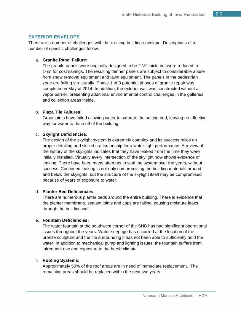
EXTERIOR ENVELOPE There are a number of challenges with the existing building envelope. Descriptions of a number of specific challenges follow.
a. Granite Panel Failure:
The granite panels were originally designed to be 2-½” thick, but were reduced to 1-¼” for cost savings. The resulting thinner panels are subject to considerable abuse from snow removal equipment and lawn equipment. The panels in the pedestrian zone are failing structurally. Phase 1 of 3 potential phases of granite repair was completed in May of 2014. In addition, the exterior wall was constructed without a vapor barrier, presenting additional environmental control challenges in the galleries and collection areas inside.
b. Plaza Tile Failures: Grout joints have failed allowing water to saturate the setting bed, leaving no effective way for water to drain off of the building.
c. Skylight Deficiencies: The design of the skylight system is extremely complex and its success relies on proper detailing and skilled craftsmanship for a water-tight performance. A review of the history of the skylights indicates that they have leaked from the time they were initially installed. Virtually every intersection of the skylight now shows evidence of leaking. There have been many attempts to seal the system over the years, without success. Continued leaking is not only compromising the building materials around and below the skylights, but the structure of the skylight itself may be compromised because of years of exposure to water.
d. Planter Bed Deficiencies: There are numerous planter beds around the entire building. There is evidence that the planter membrane, sealant joints and caps are failing, causing moisture leaks through the building wall.
e. Fountain Deficiencies: The water fountain at the southwest corner of the SHB has had significant operational issues throughout the years. Water seepage has occurred at the location of the bronze sculpture and the tile surrounding it has not been able to sufficiently hold the water. In addition to mechanical pump and lighting issues, the fountain suffers from infrequent use and exposure to the harsh climate.
f. Roofing Systems:
Approximately 50% of the roof areas are in need of immediate replacement. The remaining areas should be replaced within the next two years.

Neumann Monson Architects I HGA
2.10 State Historical Building of Iowa Renovation
STRUCTURAL SYSTEMS Provided an effective building envelope is maintained, there is reasonable expectation that the majority of the main structure will furnish sufficient capacity for a 50-year performance window. MECHANICAL SYSTEMS With the exception of the cooling towers (10.5 years remaining), all the mechanical equipment has surpassed its useful life expectancy. Ductwork at the SHB is likely lined with insulation and should be replaced due to possibility of dust accumulation, mold growth and erosion of the rubber liner. PLUMBING SYSTEMS Replacement of all plumbing equipment and piping is recommended. Piping life expectancy varies with many factors, but due to leaking in the existing building, it is recommended that all the piping be replaced and routed in areas to avoid collection storage areas and galleries. ELECTRICAL SYSTEMS The main electrical service equipment has been maintained and is in good condition. However, a number of critical systems have failed, have outlived their useful life or no longer meet the needs of the current institution. The systems in need of major upgrade include:
The building security system doesn’t meet current standards and will need to be upgraded as part of the renovation.
The building telecom and audio visual infrastructure do not meet DCA’s current needs or today’s standards for a building of this type.
The lighting and power systems do not allow the flexibility or capacity that DCA needs to program the building effectively

Neumann Monson Architects I HGA
2.11 State Historical Building of Iowa Renovation
Project Need The State Historical Building of Iowa (SHB) is at a critical juncture in its history. At 28-years-old, the building’s systems are in need of replacement, the exterior skin is failing and water infiltration is jeopardizing the state’s collection. The building’s flaws and deferred maintenance are deeply impacting the DCA’s ability to function as a cultural facility. KEY ISSUES
Failing Building Envelope
The existing SHB exterior wall was designed without a vapor barrier, which is critical to prevent the migration of water vapor through the wall system. The existing granite wall panels are failing. To fix this problem, all the exterior granite panels are required to be removed to add the required insulation and vapor barrier. Recladding with a new material is recommended, due to the breakage that is likely to happen during the granite panel removal and the added insulation will increase the dimensions of the exterior skin.
Building Flaws are Jeopardizing the Collection Extensive Water Infiltration The stepped and faceted design of the existing SHB results in a very high ratio of exterior envelope to interior area. The maintenance and repair on such a large and complex perimeter is challenging and the SHB currently suffers from extensive water infiltration from skylights, exterior walls and roof. The skylight system has been leaking since the building was opened in 1987 and is currently damaging the historic airplanes that are displayed in the atrium. Best practices for museums are to avoid skylights, which have a high failure rate, particularly in areas where artifacts are on display. In addition to leaking skylights, there have been numerous incidents of water and flooding in the lower level which house the collection storage area as well as collection preservation labs and exhibit workrooms.
Piping above Exhibits and Sensitive Collection Areas The design of a museum’s plumbing and piping system should be zoned to avoid sensitive spaces, such as exhibit galleries and collection areas. The current SHB has piping running over all the sensitive areas. There are numerous leaks which are affecting the ability to protect the collection.

Neumann Monson Architects I HGA
2.12 State Historical Building of Iowa Renovation
Building Systems are at End of Useful Life Typically, mechanical systems have a life span of 20-30 years. The SHB’s have been maintained since installation in 1987, but have not been substantially upgraded. In addition to systems being at the end of their useful life, zoning and equipment in the existing building are not up to standards for a museum with a collection to protect and preserve. The building also lacks adequate technology infrastructure. It is recommended that the full mechanical, plumbing, electrical and data systems be replaced.
Building Size and Operating Budget are Out of Alignment
The existing SHB was built for a growing collection, staff and budget. Although the collection has grown, the staff and budget have been stagnant or reduced over the years. The limited budget, along with a building that has numerous operational and maintenance challenges, has left the staff spending their time solving building issues, rather than focusing on their mission. The large building has become an increasing burden to operate and maintain.
Surrounding Environment has Changed
The surrounding neighborhood, including the East Village and the Capitol Complex, has significantly changed since the building was constructed in 1987. The design of the SHB was influenced by the context at the time of construction, resulting in a fortress to protect its contents. The thriving East Village and landscaped Capitol Complex are now amenities that can benefit and strengthen the SHB.
Challenges to Wayfinding
Multiple entries and the complex building design of the SHB result in wayfinding challenges for the visitor. Creating a single entry and simplifying the circulation would greatly benefit the visitor experience.
Compromised Visitor Experience
The SHB was built during a time when there was less emphasis on the visitor experience. Today’s successful cultural institutions put the visitor first and design the experience and amenities to support their needs.
Neumann Monson Architects I HGA
2.13 State Historical Building of Iowa Renovation
2.2 The Vision for the SHB
What Makes a Great Cultural Center? As the Department of Cultural Affairs (DCA) and Department of Administrative Services (DAS) explored ideas and plans for the future of the SHB, the museum design team was charged with the initial step to research and define “What makes a great cultural center?” Based on previous project experience, along with industry best practices, a number of criteria have been identified. The criteria were then used to objectively evaluate the existing SHB and identify opportunities for improvement.
Evolving Roles of Cultural Institutions
Cultural institutions have evolved from being custodians of cultural resources to actively engaging the public through education, interpretation and programming. This significant shift in mission from an internal focus on collection preservation to an external focus on sharing collection best practices and research with a public audience through experiential learning, is affecting the design of museums. As an active participant in the community, the role of cultural centers is continuing to evolve and should be planned for flexibility to accommodate changes in the future.
1. Civic Location
A state’s flagship museum dedicated to the history and culture of the state is most often located in close proximity to the state’s capitol building within the capital city in the state. This is true of surrounding states, including Minnesota, Wisconsin, North Dakota and Nebraska. The proximity of the museum to the capitol offers synergies in creating a well-rounded civic visitor experience for those visiting the capital city, whether on a school trip or vacation. In the case of Minnesota, the Minnesota History Center highlights and celebrates the views to the state capitol building. The viewing window and display information allows the capitol building to be the museum’s largest “artifact”.
SHB: The current location of the SHB at the base of the Capitol Complex, where government intersects with a thriving neighborhood community, is an ideal location. There are opportunities to leverage this location to create a Visitor Center and open up views to the Capitol.

Neumann Monson Architects I HGA
2.14 State Historical Building of Iowa Renovation
2. Visibility/ Relationship to the Neighborhood
A cultural center should be highly visible, have an inviting presence and make connections with the surrounding neighborhood. Although museums must be constructed to protect the contents of the collection, opportunities for glazing and transparency can be maximized at entries and public areas. Visual cues to the interior function should be conveyed to passersby, with signage supplementing the design. SHB: The existing building takes advantages of views from the rooftop terraces, but it does not engage the street or present an inviting façade to the street. Although it’s located in a highly visible location, the SHB’s design and signage does not convey its function. There is an enormous opportunity to leverage the success of the thriving East Village and create stronger connections between the SHB and the neighborhood.
3. Easy Access
In order for a cultural center to thrive, it must be easy to find and access. A majority of the visitors to a state’s cultural museum will arrive by vehicle, either by bus on a field trip or a personal vehicle. Easy on and off access from major freeways and streets is important. Pedestrians coming from the neighborhood should be welcomed and convenient access by mass transit and bicycles will enable broader access to visitors. SHB: Vehicular access to and from the SHB site is very easy from I-235. There is signage on I-235 that directs traffic to East 6th Street for arriving visitors and departing visitors gain easy access to I-235 by Pennsylvania Avenue. There is a bus service and a stop along East Grand Avenue. The infrastructure is in place to provide easy access. With additional wayfinding to the parking structure and an intuitive, single entry point, the arrival experience will be improved.

Neumann Monson Architects I HGA
2.15 State Historical Building of Iowa Renovation
4. Welcoming and Intuitive Entry
A core element of a successful cultural institution is a welcoming presence that is easy to navigate. Intuitive clues to the entry may include a large entry portal that invites you in, transparency to the lobby that piques curiosity, a gracious entry plaza with seating and information that encourages lingering. The entry experience extends beyond the building entry and the site should actively support the mission inside. Signage is highly important, but should not be relied on to overcome non-intuitive design. Ideally, there is one single entry for a cultural institution that allows for a person to greet all visitors and creates a consistent guest experience. SHB: The existing SHB does not present a welcoming or intuitive entrance experience for the first-time visitor. The main entrance on Locust is largely hidden behind the oversized canopy, which invites in vehicles, but not the pedestrian. For the visitor parking in the Grand parking structure, the entrance experience is very confusing and difficult to navigate. After parking, the visitor would cross the street at East Grand and Pennsylvania Avenue. The large colonnade invites the visitor up to the rooftop, but there is only the entrance to the Research Center at that rooftop. The north entrance to the museum is tucked in the corner and somewhat hidden for a first-time visitor. The north entrance leads you to a mezzanine level, which is not connected to the other floor levels. The visitor would then have to either take the elevator or stair down to level one to encounter a map or information for the museum. The multiple entries and confusing floor levels encountered at the north entry greatly compromise a welcoming visitor experience.
5. Designed for the Visitor
Today’s most successful cultural institutions cater to the needs of their visitors. They are accessible, family-friendly and provide modern visitor amenities. Cultural institutions are places that are activated by people wanting to learn, explore concepts and connect with others. The increased focus on the visitor experience is driving change in today’s cultural institutions, with additional thought to social and gathering spaces, as well as the flow of the visitor though the center and visitor amenities (café and museum store) to extend the visit. Generally, best practices for museums would indicate a single entry point, an information desk that can act as a control point and exhibits all on one level. SHB: The existing facility challenges the visitor by presenting different entry points, challenging wayfinding and exhibits on multiple floors. The information desk is lost in the vast entrance lobby and many visitors never interact with a person.

Neumann Monson Architects I HGA
2.16 State Historical Building of Iowa Renovation
6. Actively Engaging the Visitor
The museum experience is evolving from a passive, one-way experience (where visitors look at objects behind glass) to interactive experiences that engage the visitor at a deeper level. Flexible and technology-rich gallery spaces are the primary location for the display and interpretation of the collection. Permanent galleries provide the primary platform for the display of the visitor’s favorite objects and temporary exhibit galleries are refreshed more frequently, driving and expanding the audience and keeping the experience fresh and new. SHB: The SHB has a very large gallery size (43,525 sf) in comparison to its modest operating budget, which has resulted in exhibit halls that have not changed since the SHB opened in 1987.The exhibit hall space has become hard to easily reconfigure and update, with large gallery spaces. The static exhibits give the impression that the institution is not changing or active and do not compel a visitor to return.
7. Unique and Differentiated Experience
Whether the cultural institution charges admission or not, it must differentiate itself from other organizations/museums and understand its audiences in order to remain relevant. Exhibits, programming and educational programs should all support the institution’s mission. A state’s flagship museum should be uniquely about that state, with a representation of the unique spirit, traditions and pride of place.
SHB: The SHB has opportunities to more fully represent Iowa’s 99 counties and be more uniquely about Iowa.

Neumann Monson Architects I HGA
2.17 State Historical Building of Iowa Renovation
8. Accessible Collection
The State Historical Society of Iowa (SHSI) has a dual mission of preservation and education. As a trustee of Iowa’s historical legacy, SHSI identifies, records, collects, preserves, manages and provides access to Iowa’s historical resources. In addition, the State Archives has a mandate to ensure the essential evidence of government is created, maintained for as long as it is needed and available to the citizens of the state and to the public in general. Within most museums, the primary way for the public to access collection objects is through curated exhibits, but on average, only 3-5% of any museum’s permanent collection can be displayed in public galleries at any given time. Maximizing access to the collection and archival storage is a trend in museum best practices through the use of visible storage solutions and digitizing collection for online access. SHB: Currently, less than 2% of Iowa’s collection (which consists of over 209 million distinct pieces of Iowa history) is on display. There is a great opportunity to significantly increase public access to the collection through visible storage and digital access, greater exhibit rotation and more densely populated exhibits.


Neumann Monson Architects I HGA
2.18 State Historical Building of Iowa Renovation
2.3 The SHB of the Future Over the course of 20 weeks, the design team, along with the DCA, DAS and Ryan representatives, explored many diverse options for this project. Fixing the SHB is a challenging and difficult problem without obvious solutions, and therefore, required numerous studies to ensure all possible options were explored. The criterion identified in Section 2.2, The Vision for the SHB, was used to evaluate options and guide the course for the project. Like most architectural and planning projects, the path to the best solution was not a simple or linear path. The multiple options were evaluated on the criteria, as well as construction costs, long-term operating costs, flexibility for the future, and other museum best practices.
PROJECT GUIDING PRINCIPLES In addition to the criteria included in Section 2.2, a number of project guiding principles were identified by the DCA as being key components of a successful renovation of the SHB. Each option presented was developed with these guiding principles in mind.
Represent all 99 counties of Iowa Right-size the SHB for sustainability, best use of infrastructure and operating budgets The SHB is the preeminent place to learn about Iowa The physical building will provide the right environment needed to implement DCA’s
mandate and goals. Put more of the collection on display and increase access to the collection. Connect to the East Village and open up to the Capitol Visitor Center component provides first stop to a Capitol Complex visit Balance mission and rental events Flexibility and adaptability Technology that is flexible and adaptable in order to meet rapidly changing
technology requirements.

Neumann Monson Architects I HGA
2.19 State Historical Building of Iowa Renovation
Building Planning Approach MULTIPLE OPTIONS Numerous options and project directions were explored by the team prior to selecting a single direction to develop. The options varied in size and construction cost, with each needing to be analyzed through multiple criteria.
PROGRAM COSTS It should be noted, that in addition to construction costs, each option also has program costs associated with it which include: move expenses for the collection and DCA staff; rent for temporary homes for the above while under construction, costs for necessary collection maintenance work as well as exhibit design and construction expenses for the reinvented SHB. For each of the building options explored, the program costs are the same: $22,391,304. The following approaches were explored:
A. Demolish and Build New- Demolition of the entire existing SHB and building new on the same site.
B. Right-size and Renovate- Partial demolition of the SHB, selective building additions, and extensive renovation of the remaining existing area.
C. Variation on B- Right-size and renovate with different interior building zoning than option B.
D. Retain and Renovate Full Building- Retain the entire existing SHB and renovate the
entire building.
More than 30 planning options were evaluated during the course of the study. The grid on the following page represents a snapshot of some of those planning options. Among the options are varying amounts of demolition, new additions, configuration adjustments and total building square footages, and each option was evaluated carefully with an eye towards program function and construction cost.

Neumann Monson Architects I HGA
2.20 State Historical Building of Iowa Renovation
SHB PLANNING OPTIONS GRID

Neumann Monson Architects I HGA
2.21 State Historical Building of Iowa Renovation
A. DEMOLISH AND BUILD NEW This option explored the concept of demolishing the entire existing SHB and building new on the existing site.
Building Size 155,000 square feet Project Costs Construction Cost $95,750,000 Program Costs $22,391,304
Total Project Cost $118,141,304
Pros New building can be designed without constraints of existing footprint. New building can be designed for maximum efficiency. New building will generate enthusiasm and excitement.
Cons
Cost is prohibitive. Limited budget would mean smaller footprint than what is needed. No reuse of embodied energy/useful life of existing concrete structure. All of the collection and staff must move out and find temporary space.
Neumann Monson Architects I HGA
2.22 State Historical Building of Iowa Renovation
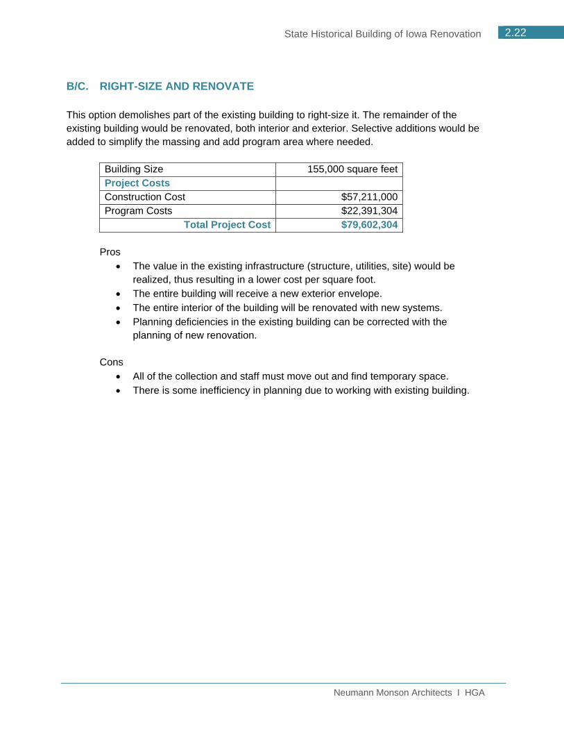
B/C. RIGHT-SIZE AND RENOVATE This option demolishes part of the existing building to right-size it. The remainder of the existing building would be renovated, both interior and exterior. Selective additions would be added to simplify the massing and add program area where needed.
Building Size 155,000 square feet Project Costs Construction Cost $57,211,000 Program Costs $22,391,304
Total Project Cost $79,602,304
Pros The value in the existing infrastructure (structure, utilities, site) would be
realized, thus resulting in a lower cost per square foot. The entire building will receive a new exterior envelope. The entire interior of the building will be renovated with new systems. Planning deficiencies in the existing building can be corrected with the
planning of new renovation.
Cons All of the collection and staff must move out and find temporary space. There is some inefficiency in planning due to working with existing building.

Neumann Monson Architects I HGA
2.23 State Historical Building of Iowa Renovation
D. RETAIN AND RENOVATE FULL BUILDING This option retains the entire existing structure and renovates the entire building.
Building Size 234,000 square feet Project Costs Construction Cost $60,400,000 Program Costs $22,391,304
Total Project Cost $82,791,304
Pros The value in the existing infrastructure (structure, utilities and site) would be
realized, thus resulting in a lower cost per square foot. The entire building will receive a new exterior envelope. There will be excess square footage (also a con).
Cons
The cost to fully renovate the entire building, along with all new systems, is cost-prohibitive.
The building’s main public space (atrium) will still be focused internally. There will be excess square footage, as the program doesn’t fill the entire
existing building. This option does not address long-term operational sustainability. This option does not address the right-sizing of spaces needed and
adjacencies required for best programming and operations. All of the collection and staff must move out and find temporary space.

Neumann Monson Architects I HGA
2.24 State Historical Building of Iowa Renovation
RECOMMENDED DIRECTION After considerable debate and discussion, the decision was made to proceed with Option B as the single option.
The existing building has a structural system that is ideal for a museum. The concrete system, with 30’x30’ bay spaces and adequate floor-to-floor height, can be reused at a cost far less than building new. Reusing the existing infrastructure already in place will allow the project to realize the value of the existing structure, utilities and site.
The west side of the building is better suited for reuse than the east side. The west
side of the building contains flexible exhibit spaces and is served by existing freight elevators. The west side accounts for roughly two-thirds of the building footprint and can be better utilized in the renovation.
The demolition of the east side of the building is being proposed to right-size the
building for operational sustainability. This approach allows for a plaza to be developed between the museum and the Capitol Complex. This plaza space is an opportunity to activate the site with programming and actively connect the museum to the East Village and Capitol. The programmatic functions of the east side will be reworked into the new footprint.
The demolition of the east side of the building allows the building’s interior public spaces to visually connect with the Capitol, creating the opportunity for the SHB to function as the Visitor Center for a visit to the Capitol.

Neumann Monson Architects I HGA
2.25 State Historical Building of Iowa Renovation
Site Analysis and Context
PROJECT LOCATION The State Historical Building of Iowa is located in the East Village neighborhood of Des Moines. It is bounded by Grand Avenue on the north, Locust Street on the south, East 6th Street to the west and Pennsylvania Avenue on the east. URBAN DESIGN AND SITE GOALS Parallel to the design process of the building, the State Historical Building renovation was studied in its larger context of the East Village neighborhood and the State of Iowa Capitol Complex. This study was undertaken in conjunction with Mario Gandelsonas, Partner of Agrest + Gandelsonas of New York. Mr. Gandelsonas was responsible for the original Des Moines Vision Plan that resulted in the Western Gateway and Pappajohn Sculpture Parks. Mr. Gandelsonas is currently developing a vison plan for a reimagined “Capitol Gateway” encompassing downtown Des Moines east of the Des Moines River. The goal of this parallel study was to develop and integrate planning for possible synergies between the SHB and its neighbors—the East Village neighborhood and Capitol Complex—with the goal of making the renovated SHB a multi-use and vibrant place over the long term.
Western Gateway to Capitol Gateway

Neumann Monson Architects I HGA
2.26 State Historical Building of Iowa Renovation
CIRCULATION AND VIEWS Both pedestrian and vehicular traffic must both be fostered in the successful site redevelopment option. Automobile traffic for visitors is primarily handled by the State of Iowa parking structure located adjacent to the northeast corner of the site at East Grand and Pennsylvania Avenues. Bus traffic is anticipated to arrive at the site from I-235 via East 6th Street with loading and unloading handled along Grand Avenue at the north edge of the site. Busses would then depart via Pennsylvania Avenue north to I-235 again. Pedestrian access occurs primarily at the corners of the site. An open plaza at the south along Locust Street gathers pedestrian traffic at the southwest from the East Village and at the southeast from the Capitol Complex. The open plaza along this edge is anticipated to draw visitors across the site in a more welcoming manner than the current condition. Pedestrian traffic enters the northeast corner of the site primarily from the parking structure. These corner access points are channeled to the main entry point in the southeast corner of the building. All building public spaces are grouped along the eastern edge of the building and enclosed primarily in glass promoting a direct, visual relationship with the Capitol as well as showcasing the activity within the building.
Reinvented SHB with entries identified as well as view corridors and vehicular drop-off circulation indicated
URBAN DESIGN The primary urban design goal is to create an entity that again contributes positively to the neighborhood—a new ‘anchor’ that can foster future development in much the same way the Meredith development anchors the Western Gateway Park. The current building has a fortress-like presence due to the conditions of the neighborhood at the time of its creation. At that time, the State Historical Building was envisioned as an agent of urban renewal that, in fact, was effective in being a catalyst for the East Side/East Village. In the thirty years since

Neumann Monson Architects I HGA
2.27 State Historical Building of Iowa Renovation
the building was completed, the surrounding neighborhood has been completely transformed from ignored and derelict structures into a vibrant community of local shops, eateries, and living options. The neighborhood has been successful because of these initial injections of activity and capital, but the building as originally planned is no longer a beneficial and appropriate entity. Much of the planning work has sought to reverse the current building presence by making public spaces transparent, putting the life and activity of the building on display. These open “see-and-be-seen” relationships contribute heavily to a successful public building and contribute significantly to the lifeblood of the neighborhood. A benefit of the proposed solution is that a significant portion of the site’s southern edge would allow for retail development on the southwestern corner and along Locust Street. This retail development would continue the pattern of development typical to the East Village, effectively extending the street level activity of the East Village farther east to the Capitol Complex. Ideally, this development would be handled through a public-private partnership so that the State Historical Building reaps the synergistic benefits of a multi-use block but is able to remain free of operating retail businesses. The current cost projections for the renovated SHB do not allow for café and gift shop amenities. These amenities are seen as vital to the renewed success of the museum and would be welcomed synergies for the redevelopment of this block.
Reinvented SHB with parcels for potential commercial development identified in blue
Neumann Monson Architects I HGA
State Historical Building of Iowa Renovation
3.1 PROGRAM INTRODUCTION
3.2 PROGRAM SPACE DESCRIPTIONS
3.3 DETAILED SPACE PROGRAM
PROGRAM DESCRIPTION 3.0


Neumann Monson Architects I HGA
3.1 State Historical Building of Iowa Renovation
3.1 Program Introduction The renovation of State Historical Building of Iowa (SHB) has an architectural space program that consists of a variety of spaces, some of which are primarily for public use, and others which are primarily spaces for staff use and collections storage. Within the renovated SHB, these spaces will be organized according to the understandings developed and summarized in this architectural space program, and organized in a way that makes the best use of the existing building and maximizes the efficiency of the building through adjacencies, flexibility and shared use of spaces. Through the process of determining the space program for the SHB, the DCA’s goal was to make sure each space in the program has a functional use and that each is designed flexibly so that as needs change in the future, spaces can be easily modified. The recognition of the fact that the current SHB, as occupied, is underutilized was a driving force behind the creation of this space program. Part 3.2 describes some of the unique aspects of a number of the key spaces in the SHB in terms of both functional characteristics as well as the aspirations of DCA. Part 3.3 consists of the detailed architectural space program which identifies each space by name, size and critical criteria as well as includes a comparison of the renovated SHB to the current SHB.
3.2 Program Space Descriptions The detailed space program consists of six categories of spaces that together make up the renovated SHB: Visitor Services, Gallery and Exhibition Spaces, Archive & Collections Storage and Support, Research Center/Learning Labs/Meeting Rooms, and Building Support. The spaces that make up each of these categories are unique to the renovated SHB, and many are unique to a state historical museum and archive building. Each category is summarized below.
VISITOR SERVICES As the state’s premier visitor center, the renovation of the SHB will use its lobby and other public circulation spaces to provide visitors with an introduction to Iowa via an Iowa 101 exhibit as well as serve as a gateway to the Capitol Complex. The Iowa 101 exhibit will be housed within the main public spaces of the building and will introduce Iowa to the visitor as well as provide information on historic sites and other sites of interest throughout each of the state’s 99 counties. In this way, the SHB will not only provide access to the state’s collections but will also connect visitors to the many significant sites and attractions across Iowa, along with the history of the state. This space functions as a gallery and gathering space. From this space, which exists on multiple levels, access will be provided to key visitor spaces like the exhibit galleries,

Neumann Monson Architects I HGA
3.2 State Historical Building of Iowa Renovation
auditorium, learning labs, research center and meeting rooms. Additionally this space will provide access to the "Collection Viewing Lobby" that provides a view into the state's collection in the lower level. The lobby will also serve to connect typical visitor support spaces and provide space for additional visitor amenities. After hours, the lobby is a space that the DCA could rent for events, providing the department with additional revenue that can be used to support its programs. The 250-seat auditorium will be renovated and is another key component that will support both the Visitor Center experience as well as provide a place for the DCA to present and host events that showcase Iowa’s arts, culture and history. One of the DCA’s key goals for this project is to improve the visitor experience; the spaces described above are a key component of that experience.
GALLERY AND EXHIBITION SPACES The renovation of the SHB will provide new exhibit gallery spaces for an updated and more interactive presentation of Iowa’s history. Modern technology, exhibit design and storytelling methods will be used to tell the stories that make Iowa what it is. The gallery & exhibition spaces will be flexible and the technology will be sustainable allowing for the creation of exhibits of various sizes and for ease of exhibit changeover. The exhibit galleries will be of various sizes and will house a variety of exhibit types; more collection galleries, easily changeable exhibit galleries to showcase different parts of the collection providing greater visibility to more of the SHSI collection, galleries for temporary exhibits highlighting a specific Iowa county or Iowan, and possibly a gallery geared towards children.
ARCHIVE & COLLECTION STORAGE AND SUPPORT The SHB houses the state’s collection which include both an object collection as well as the largely paper collection of the State Archives and Research Center. A significant amount of square footage in the SHB is dedicated storage space for these collections. The space allocated was arrived at through working with the SHSI staff and utilizes high-density storage furniture to maximize the amount of storage within each volume. Adjacent to each of the collections storage areas are spaces to support working with and on the artifacts, books and documents in the collections. These support spaces include workrooms, a conservation lab, and a carpentry shop, as well as an acquisitions processing area that includes an isolation room.

Neumann Monson Architects I HGA
3.3 State Historical Building of Iowa Renovation
RESEARCH CENTER, LEARNING LABS AND MEETING ROOMS A key element of the charge of the DCA is to educate Iowans about Iowa art, history and culture, and to provide access to the state’s history including the museum, archives, research center and special collection. A key goal of the DCA is for the SHB to be a gathering place for Iowans. The spaces described in this section of the program are critical to fulfilling those needs. The Research Center is a space where Iowans and researchers from outside of Iowa can come to gain access to the SHSI collection through working with staff. The Learning Labs are interactive classroom spaces that are used as a key part of SHSI’s educational programs for teaching Iowa students about Iowa. The classrooms provide a space for hands-on learning activities that are supported by presentations made in the auditorium and by visiting the exhibit galleries. The Meeting Rooms provide a space for the DCA to invite outside groups into the SHB for meetings and events. These spaces can be used to support DCA programming and events, or they could be rented to groups attracted by the SHB’s amenities and proximity to the Capitol.
ADMINISTRATION, STAFF AND OPERATIONS SPACES The SHB not only houses Iowa’s collection, state museum, state archives and Research Center, but it provides the home base for the DCA staff. DCA staff offices are a key component of the SHB. The desire in the renovated SHB is to bring all of the staff together into one space to provide for better staff interaction not currently possible due to the layout of the existing building. This category of spaces includes office space for staff, a series of meeting rooms for use by staff, a reception area, storage and a workroom.
BUILDING SUPPORT The building support category includes the spaces that allow the building to function in a way that serves and protects the collection, the museum and the staff. Included are the mechanical, electrical, fire protection and utility services for the building as well as the loading and receiving areas, janitorial closets and storage spaces, and general building storage. One key element of the new program is the addition of a loading/receiving/trash area for non-museum functions which will allow food and other potentially damaging materials to be kept separate from collection and museum functions.


Neumann Monson Architects I HGA
3.4 State Historical Building of Iowa Renovation
3.3 Detailed Space Program
The following pages describe the detailed architectural space program which identifies each space by name, size and critical criteria and includes a comparison of the renovated SHB (proposed) to the current SHB (existing).

Neumann Monson Architects I HGA
3.5 State Historical Building of Iowa Renovation

Neumann Monson Architects I HGA
3.6 State Historical Building of Iowa Renovation

Neumann Monson Architects I HGA
3.7 State Historical Building of Iowa Renovation

DRAFT
1/21/2016 Neumann Monson Architects I HGA
3.8 State Historical Building of Iowa Renovation

DRAFT
1/21/2016 Neumann Monson Architects I HGA
3.9 State Historical Building of Iowa Renovation

Neumann Monson Architects I HGA
3.10 State Historical Building of Iowa Renovation

Neumann Monson Architects I HGA
3.11 State Historical Building of Iowa Renovation

Neumann Monson Architects I HGA
3.12 State Historical Building of Iowa Renovation


Neumann Monson Architects I HGA
State Historical Building of Iowa Renovation
4.1 DRAWINGS
DRAWINGS 4.0


Neumann Monson Architects I HGA
4.1 State Historical Building of Iowa Renovation
4.1 Drawings DRAWINGS
The following pages include drawings of the concept for the State of Iowa Historical Building Renovation and include the following:
Site Plan Floor Plans Renderings

Neumann Monson Architects I HGA
4.2 State Historical Building of Iowa Renovation
SITE PLAN
The State Historical Building of Iowa Renovation will foster the development of a successful pedestrian and vehicular redevelopment for the entire block. The renovation will focus on improving pedestrian access to the entrance of the building, gathering pedestrian traffic at the corners of the site and focusing them into the main entry point, a simplified experience from what exists today. An open plaza at the south along Locust Street gathers pedestrian traffic at the southwest from the East village and at the southeast from the Capitol Complex. The open plaza along this edge is anticipated to draw visitors across the site in a more welcoming manner than the current condition. Pedestrian traffic enters the northeast corner of the site primarily from the parking structure. All building public spaces are grouped along the eastern edge of the building and enclosed primarily in glass promoting a direct, visual relationship with the Capitol as well as showcasing the activity within the building.

Neumann Monson Architects I HGA
4.3 State Historical Building of Iowa Renovation
LOWER LEVEL FLOOR PLAN
The Lower Level of the building houses the State Historical Museum object collection as well as the spaces needed for the staff to work with the objects for both preservation purposes and exhibit preparations. Some of the collections and exhibit support spaces located on this level include a Collection Workroom, Carpentry Shop, Conservation Lab and Acquisitions and Processing space for new objects coming into the collection. A new feature of the renovated SHB is the Collection Viewing Lobby which is accessed from the Main Level Lobby via stair and elevator and allows visitors a peek behind the scenes into the collections storage area through glass walls. Service access from the main loading dock to this level remains in the northwest corner and now serves only Museum, Archive and Research Center functions removing the potential for contamination by other building trash and deliveries. The main mechanical and electrical equipment that serve the facility are also located on this level.

Neumann Monson Architects I HGA
4.4 State Historical Building of Iowa Renovation
MAIN LEVEL FLOOR PLAN
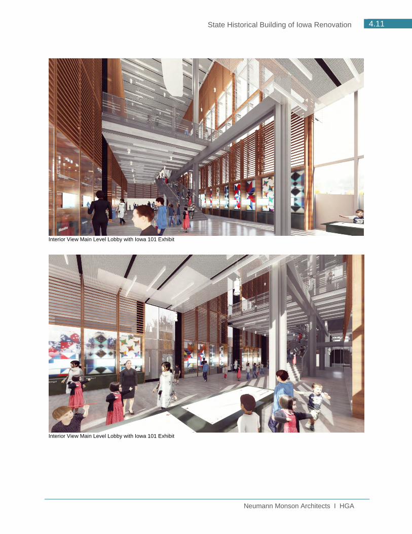
There is one entrance to the renovated SHB, into a vestibule from the south off of Locust Street and from the east off of the Plaza. Upon entering, one arrives at an information desk before proceeding into the three-story lobby space that is home to a new Iowa 101 exhibit and has incredible views to the Capitol through a new glass wall on the east side of the building. The Main Level is home to a renovated auditorium, a series of four learning labs that will be home to the Museum’s education programs, the Archive and Special Collections, Research Center and workspace for staff. There is an abundance of windows into these spaces from the lobby which allows more of the building activity and collection to be on display for visitors. A second loading dock is located at the southwest corner of the building to allow for non-Museum and Archive related deliveries to occur in a separate area, better securing the Museum collection and Archive from potential contamination from food and trash. Additional support spaces are also located on this level, including a catering support space for events.

Neumann Monson Architects I HGA
4.5 State Historical Building of Iowa Renovation
SECOND LEVEL FLOOR PLAN
The Second Level of the renovated SHB houses primarily the Exhibit Galleries. One comes up to this level via an open stair in the atrium, catching views of the Capitol to the east as you climb or via a new glass elevator. One enters the galleries through the Great Hall Gallery which provides a view out towards the East Village at the west end and is lined by visible storage display cases. These cases will allow the Museum to provide greater access to the collections through densely populated displays that visitors can take in as they move in and out of the galleries located to the north and south of the Great Hall Gallery. The gallery on the northwest corner will have windows allowing a glimpse into the museum for people driving down East 6th Street. The exhibit galleries are intended to be very flexible spaces that will allow for and accommodate exhibits of varying sizes that can be reconfigured easily and have the infrastructure to support all lighting and technology needs.

Neumann Monson Architects I HGA
4.6 State Historical Building of Iowa Renovation
THIRD LEVEL FLOOR PLAN
The Third Level of the renovated SHB is home to the administrative offices of the Department of Cultural Affairs. All of the staff, currently spread throughout the existing building, will be co-located for better staff interaction. The exterior walls of the office area will be opened up to provide more natural light and view into the staff spaces. Additionally, this level has two large meeting rooms that can host events and programs the DCA offers or can be rented to community members for meetings or other events. This level caps the three level lobby space and has phenomenal views to the east and access to a roof terrace.

Neumann Monson Architects I HGA
4.7 State Historical Building of Iowa Renovation
PROJECT RENDERINGS
Bird’s Eye View with potential Commercial Development
Northwest Corner / East 6th Street

Neumann Monson Architects I HGA
4.8 State Historical Building of Iowa Renovation
Southwest Corner with potential Commercial Development
View from Capitol with potential Commercial Development

Neumann Monson Architects I HGA
4.9 State Historical Building of Iowa Renovation
Northeast View / Walk from Parking Structure with potential Commercial Development
View from Pennsylvania Avenue with potential Commercial Development

Neumann Monson Architects I HGA
4.10 State Historical Building of Iowa Renovation
South View at Entry with potential Commercial Development
Interior View Looking at Capitol
Neumann Monson Architects I HGA
4.11 State Historical Building of Iowa Renovation
Interior View Main Level Lobby with Iowa 101 Exhibit
Interior View Main Level Lobby with Iowa 101 Exhibit

Neumann Monson Architects I HGA
4.12 State Historical Building of Iowa Renovation
Interior View Second Level Lobby
Interior View Lower Level Collections Viewing Lobby looking south

Neumann Monson Architects I HGA
State Historical Building of Iowa Renovation
5.1 ARCHITECTURAL NARRATIVE
5.2 STRUCTURAL NARRATIVE
5.3 MECHANICAL NARRATIVE
5.4 ELECTRICAL NARRATIVE
NARRATIVES 5.0


Neumann Monson Architects I HGA
5.1 State Historical Building of Iowa Renovation
5.1 Architectural BASIS OF DESIGN – EXTERIOR ENVELOPE
The following represents the basis of design for the exterior envelope replacement for the SHB renovation. Supplemental information can be found in the Scope Narrative in Section 6.4 of this report.
A. Curtainwall/Windows/Glazing in Galleries
1. Curtain Wall: Wausau HP-Wall. 2. Glazing: Nominal 1-13/16” IGU, as follows:
a. Outboard Lite: 1/4”clear glass with Viracon VE1-2M low-e coating on No. 2 surface.
b. Airspace: 1/2” argon-filled space, black-painted aluminum spacer, black silicone.
c. Center Lite: 1/4” laminated lite consisting of 2 plies of 1/8” clear glass, 0.060” UV-blocking PVB interlayer, with Viracon VE1-85 low-e coating on No. 6 surface.
d. Airspace: 1/2” argon-filled space, black-painted aluminum spacer, black silicone.
e. Inboard Lite: 1/4” clear glass.
B. Curtainwall/Windows/Glazing in Lobby
1. Curtain Wall: Wausau HP-Wall. 2. Glazing: Nominal 1-3/4” IGU, as follows:
a. Outboard Lite: 1/4”clear glass with Viracon VE1-2M low-e coating on No. 2 surface.
b. Airspace: 1/2” argon-filled space, black-painted aluminum spacer, black silicone.
c. Center Lite: 1/4” clear glass with Viracon VE1-85 low-e coating on No. 6 surface.
d. Airspace: 1/2” argon-filled space, black-painted aluminum spacer, black silicone.
e. Inboard Lite: 1/4” clear glass.
C. Curtainwall/Windows/Glazing in Offices/Other
1. Curtain Wall: Wausau SuperWall 2. Glazing: Nominal 1” IGU, as follows:
a. Outboard Lite: 1/4”clear glass with Viracon VE1-2M low-e coating on No. 2 surface.
b. Airspace: 1/2” argon-filled space, black-painted aluminum spacer, black silicone.
c. Inboard Lite: 1/4” clear glass.

Neumann Monson Architects I HGA
5.2 State Historical Building of Iowa Renovation
D. Exterior Skin
Metal Panel Rain Screen System Wall make-up:
a. CMU backup wall (reuse existing CMU if it can accommodate current wind load requirements, if not, provide new, appropriately reinforced, CMU back up)
b. Fluid Applied Moisture Barrier 60 mils (Grace Procor 75) c. 4-5” mineral insulation (Thermafiber Rain Barrier) + vertical z-furring d. Horizontal hat channels e. Metal panel; Centria 1W-10A
E. Roof
a. Hot applied moisture barrier on concrete substrate b. Insulation R-30 c. DAS preferred roofing system
F. Roof Terrace
Hot Fluid-Applied Rubberized-Asphalt Roofing Systems:
Ultimate Assembly by American-Hydrotech. a. Primary Membrane: MM6125 by American Hydrotech. b. Root Barrier & Drainage Course c. High-Density Extruded Polystyrene Insulation d. Geotextile Filter Fabric e. Adjustable Pedestals f. Concrete Pavers:

Neumann Monson Architects I HGA
5.3 State Historical Building of Iowa Renovation
5.2 Structural BASIS OF DESIGN The following represents the basis of design for the structural systems for the renovated State Historical Building of Iowa. No structural analysis has been provided at this time. It is assumed that the existing structure will be sufficient as there is no change to loading from the previous usage. A minimum 22’-0” floor to floor height will be maintained, allowing for a minimum clear height of 19’-3” under the structure and allowing for a 10’-0” finished ceiling height in office spaces.
1. The renovated State Historical Building of Iowa will utilize the existing building components which are already compatible with the loading for museum and museum storage functions and on an ideal 30’ x30’ module. Existing components are as follows:
Structural Frame: Reinforced concrete beams and columns Supported Floors: Reinforced concrete pan joist system Roof Deck: Reinforced concrete pan joist system Exterior Walls: Reinforced concrete and concrete block masonry Interior stairs: Steel pan, concrete filled
2. New constructions and modifications to the existing building components will be as
follows: Special Foundations: No deep foundations or special foundations are
expected at this time. Footings/Foundations: 4000 PSI concrete, sized accordingly for new
walls, etc. Below Grade Wall: 4000 PSI Concrete, sized accordingly for new
walls, etc. Structural Frame: Reinforced concrete beams and columns or
steel column and beams Supported Floors: Reinforced concrete pan joist system or steel
beams and decking Roof Deck: Reinforced concrete pan joist system or steel
decking Exterior Walls: Reinforced concrete, concrete block masonry or
metal studs Interior stairs: Steel pan, concrete filled Architectural Stair: TBD, steel structure


Neumann Monson Architects I HGA
5.4 State Historical Building of Iowa Renovation
5.3 Mechanical MECHANICAL SYSTEMS BASIS OF DESIGN
A. EXECUTIVE SUMMARY
1. The renovated State Historical Building of Iowa will utilize new mechanical systems
that provide stable temperature, humidity and pollutant control for museum-critical and human-comfort spaces. All existing mechanical systems shall be removed and replaced with appropriate modern systems. The museum will be served by distributed central station air handling units. Units will have high-efficiency particulate and gas-phase filtration with high-purity steam humidification. Chilled water will be produced using efficient centrifugal water-cooled chillers and fluid coolers. Building heating water will be produced using natural gas condensing boilers. Redundancy will be incorporated to reduce the risk of system downtime. Sensitive museum areas will have water piping (domestic water, hydronic heating and cooling) physically separated as much as possible.
2. Museums and critical collections storage areas consume more energy than comparably sized buildings. It is anticipated that system energy efficiency shall be evaluated and integrated with MidAmerican Energy’s energy efficiency evaluation program to effectively provide cost effective energy efficiency conservation measures while still meeting museum and critical collections storage requirements.
B. HVAC DESIGN CRITERIA
1. Indoor (Space Design Criteria) Cooling Dry
Bulb Temperature (degrees F)
Cooling Relative Humidity (percent)
Heating Dry Bulb
Temperature (degrees F)
Heating Relative Humidity (percent)
ASHRAE Class of Control
Public Collection (Galleries)
70ºF +/- 5ºF 50% +/-
10% 70ºF +/- 5ºF 50% +/- 10% A**
Non-Public Collection (Storage/Receiving)
70ºF +/- 5ºF 50% +/-
10% 70ºF +/- 5ºF 50% +/- 10% A**
Public Circulation Areas connected to Public Collection and Non-Public Collection Spaces
75ºF +/- 9ºF 50% +/-
10% 70ºF +/- 9ºF
40% +/- 10% (system
average, not space
specific)
B**

Neumann Monson Architects I HGA
5.5 State Historical Building of Iowa Renovation
*Temperature and Humidity requirements for Public Collection, Non-Public Collection, and Public Circulation adjacent to collection spaces require confirmation with Owner and Museum Staff. ** Intent of Design Criteria is to align/match with all related time periods and fluctuations listed in the 2015 ASHRAE Applications Handbook in Chapter 23 Museum, Galleries, Archives and Libraries type AA, A and B (depending on space) level of control listed in Table 3. Human Comfort Areas (Non-critical Circulation / Lobbies, Offices, Public and Non-Public Spaces)
76ºF +/- 3ºF 50% +/-
N/A 70ºF +/- N/A
No winter humidification
N/A
Vestibules 80ºF +/- N/A N/A 65ºF +/- N/A No winter
humidification N/A
Mechanical / Electrical Rooms
80ºF +/- N/A N/A 65ºF +/- N/A No winter
humidification N/A
Telecom Rooms 75ºF +/- N/A 50% +/-
N/A 65ºF +/- N/A
No winter humidification
N/A
Loading Dock N/A N/A 50ºF +/- N/A No winter
humidification N/A
C. HVAC SYSTEMS
1. Heating Water System a. The preliminary estimated building heating load is 5,000 MBH b. Two 3,000 MBH (input) fully condensing natural gas firetube boilers will provide
hot water for distribution throughout the building. c. Natural gas service size shall require coordination and confirmation with utility.
If natural gas service is too small, a cost-effectiveness evaluation of natural gas shall be required.
*Note, based on museum energy consumption profiles, the use of electricity for building heating is not recommended due to anticipated energy cost of electric heating vs natural gas heating. d. The heating hot water plant will be designed for operation with a maximum
heating water supply temperature of 160°F. Hot water supply temperature will be reset based on outdoor air temperature allowing for boilers to operate at highest efficiencies during non-peak outdoor air conditions. Normal water temperature difference is 30°F with some terminal heating equipment having a temperature difference as low as 20°F.

Neumann Monson Architects I HGA
5.6 State Historical Building of Iowa Renovation
e. Two (2) variable speed heating water pumps will distribute heating water to air handling unit heating coils, preheat coils and heating terminal devices such as unit heaters, VAV boxes, duct heating coils and fintube radiation. The pumps will operate in parallel with a lead/lag control sequence. 1) Individual boiler load pumps will be provided to meet boiler manufacturer
minimum flow requirements. f. All air handling units shall have a local inline circulating pump for freeze
protection purposes located at the preheat coil. g. Boilers, heating water pumps, freeze protection pumps and associated control
panels will be on emergency power to maintain building heating and reheat operation.
h. Four-pipe fan coil units will be provided in each entry vestibule. i. A combination of gas-fired infrared radiant heaters and hot water unit heaters
will be provided for loading dock heating. j. Hot water piping accessories
1) Pump suction diffusers (for end suction pumps) 2) Diaphragm compression tank(s) 3) Air separators 4) Chemical feeders 5) Calibrated balancing valves 6) Strainers 7) Inlet and discharge double spherical flexible connections.
k. Hot water piping systems will be 125 PSIG minimum working pressure. l. Pressure independent control valves are recommended for air handling unit
heating coils and any other large heating loads that support museum and critical space temperature and humidity control.
m. Heating water piping 3 inches and larger will be Schedule 40 black steel pipe with welded, threaded, or flanged fittings. Piping may be copper tube with solder joint fittings for pipe sizes 2.5-inch and smaller.
n. Valves in heating water piping systems will be ball valves for sizes up to and including 3-inches and butterfly valves for sizes 4-inches and larger.
o. Heating water piping will be insulated with fiberglass insulation with a foil-scrim-kraft vapor barrier jacket covering in all areas except where exposed within 8’-0” of the finished floor. Exposed piping in occupied areas within 8-0” of the finished floor shall have a PVC jacket. Piping in mechanical rooms shall have a PVC jacket. Insulation thickness will be as required to minimize thermal losses on hot water piping and will at a minimum comply with the energy code.
p. Pumps will be supported on vibration isolators with an inertia base. q. Piping within the mechanical room or within a minimum of 75 feet of a pump will
be hung from spring and neoprene vibration isolators (Mason Industries type PC-30N or equal).
2. Chilled Water System a. The preliminary estimated cooling load for the building is 600 tons.

Neumann Monson Architects I HGA
5.7 State Historical Building of Iowa Renovation
b. Two (2) 400 ton energy-efficient centrifugal water-cooled chillers will be provided for operation and maintenance flexibility. The efficiency rating of the chiller will be evaluated in subsequent design phases. Consideration will be given to initial costs, life cycle operational costs, system flexibility and load profiles.
c. A heat recovery chiller could be included as a part of the chilled water plant to maximize energy efficiency performance. Heat recovery chiller would be anticipated to match baseline reheat loads for require temperature and humidity control.
d. The chilled water system will be a primary/secondary pumping arrangement designed with a 42°F chilled water supply water temperature. The design chilled water temperature difference will be 16°F.
e. Two (2) variable speed primary chilled water pumps will circulate chilled water through the cooling plant and will utilize a buffer tank. Pumps will be base-mounted and suction or vertical split case type. Pumps will be operated in parallel with a lead/lag control sequence.
f. Two (2) variable speed secondary chilled water pumps will distribute chilled water to air handling unit cooling coils, fan coil unit cooling coils and other miscellaneous chilled water equipment. Pumps will be base-mounted and suction or vertical split case type. The pumps will be operated in parallel with a lead/lag control sequence.
g. Chilled water piping accessories: 1) Pump suction diffusers (for end suction pumps) 2) Diaphragm compression tank 3) Air separator 4) Chemical feeders 5) Calibrated balancing valves 6) Strainers 7) Pump inlet and discharge double spherical flexible connections. 8) Automatic flow control valve (one per chiller).
h. Chilled water piping systems will be 125 PSIG minimum working pressure. i. Pressure independent control valves will be used on all AHU cooling coils. j. Chilled water piping 3 inches and larger will be Schedule 40 black steel pipe
with welded, threaded, or flanged fittings. Piping may be copper tube with solder joint fittings for pipe sizes 2.5-inch and smaller.
k. Valves in chilled water piping systems will be ball valves for sizes up to and including 3-inches and butterfly valves for sizes 4-inches and larger.
l. Interior chilled water piping will be insulated with phenolic insulation with an all service jacket. Exposed piping in occupied areas within 8’-0” of the finished floor shall have a PVC jacket. Piping in the mechanical rooms shall have a PVC jacket. Insulation thickness will be as required to minimize thermal losses on hot water piping and will at a minimum comply with the energy code.
m. Pumps will be supported on vibration isolators with an inertia base.

Neumann Monson Architects I HGA
5.8 State Historical Building of Iowa Renovation
n. Chilled water piping within the mechanical room or within a minimum of 75 feet of a pump will be hung from spring and neoprene vibration isolators (Mason Industries type PC-30N or equal).
o. Connections at air handling units and other heating equipment will have double spherical flexible connections.
3. Condenser Water System (applicable to water-cooled chiller plant only) a. Two (2) stainless steel closed circuit cooling towers will be provided for
operation and maintenance flexibility. Each cooling tower will be sized to match each chiller.
b. The closed circuit cooling towers shall be capable of operating in a dry mode for winter operation.
c. The following features shall be provided with the closed circuited cooling tower: 1) Variable speed drive for each tower fan 2) Ultra-quiet fan (sound levels will be reviewed by the project Acoustician) 3) Fan cylinder extension to match the height of the cooling tower screened
enclosure 4) Water level controller 5) Air inlet screens and positive closure dampers 6) Electric basin heaters 7) Top of tower guardrail complete with knee rail and toe board that comply
with OSHA requirements 8) Distribution basin platform and guardrail 9) Access door platform and guardrail 10) Internal plenum walkway and interior mechanical equipment access platform
and ladder between the plenum walkway and equipment access platform d. The condenser water system will be 35% propylene glycol for freeze protection
purposes. e. Two (2) variable speed condenser water pumps will distribute condenser water
to cooling towers. Pumps will be base-mounted and suction or vertical split type. The pumps will be operated in parallel with a lead/lag control sequence.
f. Condenser water piping accessories: 1) Pump suction diffusers (for end suction pumps) 2) Diaphragm compression tank 3) Air separator 4) Chemical feeders 5) Calibrated balancing valves. 6) Strainers. 7) Seismic expansion joint across any building structural isolation joints. 8) Pump inlet and discharge double spherical flexible connections. 9) Automatic flow control valves (one per chiller and one per tower section). 10) Cooling tower water treatment for tower spray water 11) Glycol fill station
g. Condenser water piping system will be 125 PSIG minimum working pressure.

Neumann Monson Architects I HGA
5.9 State Historical Building of Iowa Renovation
h. Indoor condenser water piping 3 inches and larger will be Schedule 40 black steel pipe with welded, threaded, or flanged fittings. Piping may be copper tube with solder joint fittings for pipe sizes 2.5-inch and smaller.
i. Valves in condenser water piping systems will be ball valves for sizes up to and including 3-inches and butterfly valves for sizes 4-inches and larger.
j. Interior condenser water piping will be insulated with phenolic insulation with an all service jacket. Exposed piping in occupied areas within 8’-0” of the finished floor shall have a PVC jacket. Piping in the mechanical rooms shall have a PVC jacket. Insulation thickness will be as required to minimize thermal losses on hot water piping and will at a minimum comply with the energy code.
k. Pumps will be supported on vibration isolators with an inertial base. l. Piping within the mechanical room or within a minimum of 75 feet of a pump will
be hung from spring and neoprene vibration isolators (Mason Industries type PC-30N or equal)
m. A plate and frame heat-exchanger will be provided as a part of the condenser water system for water-side free cooling. The heat exchanger will be located in a side stream configuration in order to operate in a partial free cooling mode.
4. Central Air Handling Units a. Gallery and collection systems
1) Air handling units will be variable volume, variable temperature type units with no air-side economizer with an estimated 10% outdoor air.
2) The units will be custom 4” double-wall units arranged (back to front) as follows: (a) Mixing section with return air inlet and minimum outdoor air inlet (b) Prefilter: MERV 8, two-inch thick pleated panel (c) Activated charcoal (gas) phase filtration system (rack type) (d) Post filter: MERV 8, two-inch thick pleated panel (e) Final filter: MERV 14, twelve-inch thick cartridge type. (f) Hot water heating coil: 2-row coil with design entering water temperature
of 160F and leaving water temperatures of 130F. (g) Chilled water cooling coil: 10 row coil with design entering water
temperature of 43F and leaving water temperature of 58F (h) Coils shall be selected to meet space temperature and humidity control
requirements while balancing air pressure drop and energy efficiency requirements.
(i) Steam humidifier dispersion section (j) Supply Fan: Multiple plenum type centrifugal airfoil fans. (k) Discharge air section
3) Dedicated mixed flow inline relief fans will be provided for the galleries in order to control space pressurization.
b. Non-gallery and non-collection systems 1) Air handling units will be variable volume and variable temperature type
units with an estimated 20% outdoor air.

Neumann Monson Architects I HGA
5.10 State Historical Building of Iowa Renovation
2) The units will be semi-custom 2” double-wall units arranged (back to front) as follows: (a) Return air inlet (b) Return/Relief air fan: Multiple plenum type centrifugal airfoil fans (c) Relief air section with relief air damper (d) Mixing section with return air damper, minimum outdoor air damper and
economizer damper. (e) Prefilter: MERV 8, two-inch thick pleated panel (f) Final filter: MERV 14, twelve-inch thick cartridge type (g) Hot water heating coil: 2-row coil with design entering water temperature
of 160F and leaving water temperatures of 130F (h) Chilled water cooling coil: 10 row coil with design entering water
temperature of 43F and leaving water temperature of 58F (i) Coils shall be selected to meet space temperature and humidity control
requirements while balancing air pressure drop and energy efficiency requirements.
(j) Supply Fan: Multiple plenum type centrifugal airfoil fans. (k) Discharge air section
c. Upper Level Offices Unit 1) Air handling unit will be variable volume and variable temperature type unit
with an estimated 15% outdoor air. 2) The units will be a semi-custom, rooftop unit, with double-wall construction
arranged (back to front) as follows: (a) Return air inlet (b) Return/Relief air fan: Multiple plenum type centrifugal airfoil fans (c) Relief air section with relief air damper (d) Mixing section with return air damper, minimum outdoor air damper
and economizer damper. (e) Prefilter: MERV 8, two-inch thick pleated panel (f) Final filter: MERV 14, twelve-inch thick cartridge type
(g) Hot water heating coil: 2-row coil with design entering water temperature of 160F and leaving water temperatures of 130F
(h) Chilled water cooling coil: 10 row coil with design entering water temperature of 43F and leaving water temperature of 58F
(i) Supply Fan: Multiple plenum type centrifugal airfoil fans. (j) Discharge air section
d. Dedicated Outdoor Air Pretreatment Unit(s) 1) The project may significantly benefit from the use of dedicated outdoor air
pretreatment air handling units or system configurations that pre-condition or treat outdoor air. These systems would be expected to reduce overall energy consumption, reduce peak cooling and heating loads, and provide more stable ventilation air temperature and humidity to museum and critical collections units.

Neumann Monson Architects I HGA
5.11 State Historical Building of Iowa Renovation
2) Examples of these types of systems would include energy recovery wheels (sensible and total / latent), run-around coils, air-exchanging systems, earth-tubes, passive solar heating building elements, etc.
5. VAV System Zoning a. All zones are VAV with most spaces having hot water reheat coils. Spaces not
requiring reheat would be limited to lightly loaded data, electrical or AV rooms. b. Any zones which have airflows outside the range of a VAV box will be provided
with a built-up VAV box consisting of a motorized damper, duct reheat coil and airflow measuring station.
c. No hot water coils or piping will be located in collection spaces.
6. Terminal Heating Units a. Recessed fintube or custom fintube radiation with custom covers will be
provided at all curtain wall locations. b. Four pipe fan coil units will be provided in entry vestibules and will be
suspended from spring and neoprene vibration isolators (Mason PC-30N). c. Hot water cabinet unit heaters will be provided in exterior stairs. d. Unit heaters will be provided in any mechanical spaces that do not require
tempering/cooling. e. Gas-fired radiant heater(s) will be located over the working area of the enclosed
loading dock.
7. Main Electrical Room / Server Room / Dimmer Room Cooling Systems a. Server and dimmer rooms with high heat loads will be cooled by computer room
units located inside the room with chilled water coming from the chilled water system.
b. Chilled water mini-split ductless fan coil units will be used for smaller electrical and telecom rooms with cooling loads less than 24,000 BTU/h. Mini-split ductless fan coil units will be wall supported with neoprene mounts.
c. Chilled water fan coil units will be provided for electrical and telecom rooms with cooling loads greater than 24,000 BTU/h. Fan coils will be suspended from spring and neoprene vibration isolators (Mason PC-30N), and will not be located in or in direct communication with noise critical spaces as defined by the project Acoustician.
8. Humidification Systems a. Highly accurate humidification systems that are easy to maintain shall be used.
Electric resistive element steam humidifiers or gas fired steam humidifiers with direct injection manifolds will be used for all areas of the building requiring humidification.
b. Humidifiers will be packaged units with electrically heated immersion heaters, stainless steel tank, factory controls and suitable for use with deionized/reverse osmosis water.
c. Air handling steam dispersion manifolds will be stainless steel, insulated tubes. d. Deionized/reverse osmosis water will be used for humidification make-up water.

Neumann Monson Architects I HGA
5.12 State Historical Building of Iowa Renovation
9. Exhaust Systems a. Toilet rooms, custodial closets and green rooms will be exhausted to the
building exterior. b. Hydraulic elevator equipment rooms will be exhausted to the building exterior
with an independent system. c. A variable air volume loading dock exhaust system will exhaust air at the
minimum rate of 0.05 cfm per square foot and maximum rate of 0.75 cfm per square foot. The system will maintain a negative pressure relative to the building. The rate of exhaust air flow will be operated via carbon monoxide and nitrogen dioxide detectors.
d. A standalone exhaust system will be provided for any vented storage cabinets located within the building.
e. Exhaust fans will be a combination of roof mounted powered roof ventilators and inline fans located in mechanical rooms. Any inline exhaust fans will be ducted to exhaust louvers, gravity roof ventilators or louvered penthouses. Exhaust locations will be located so that re-entrainment of exhaust air is minimized. Any roof mounted equipment should be located in a screened area. An alternative to a screened area would be low profile visually appealing louvered penthouses. Fans located in mechanical rooms will be supported with spring and neoprene vibration isolation hangers. Roof mounted exhaust fans will be mounted on a curb with a neoprene pad.
f. Flexible connections shall be provided at ductwork connections to all fans, fan plenums or fan casings.
g. A three horsepower portable dust collection system with source-point collection arm will be provided in one of the work rooms.
10. Air Distribution System a. All systems (supply, return and exhaust) will be ducted. b. Supply, return, outdoor air, and exhaust ductwork will be fabrication of
galvanized sheet metal in rectangular, oval and round shapes according to SMACNA Duct construction Standards for 2” and 4” pressure classification, and for Class A duct sealing. Insulated flexible ducts will be used for connection from supply air ducts to outlets above ceilings. Four-inch pressure class ductwork will be used for all supply ducts upstream of terminal units in variable air volume systems. Two-inch pressure class ductwork will be used for supply ducts downstream of air terminal units and any constant volume systems. Return ductwork will be 4” pressure class throughout. Exhaust ductwork will be 2” or 4” pressure class as appropriate for each system.
c. Supply and return ducts in mechanical rooms, shafts and above ceilings will be insulated with external fiberglass duct insulation with a foil-scrim-kraft vapor barrier jacket covering. Insulation thickness will at a minimum comply with the energy code. Ductwork exposed in finished occupied spaces may be lined (rectangular ducts) or double wall spiral (round duct). Exhaust ducts will be insulated within fifteen feet of the exterior envelope. Outdoor air ducts will be

Neumann Monson Architects I HGA
5.13 State Historical Building of Iowa Renovation
insulated with a minimum of three inches of closed cell insulation with an integral vapor barrier and a PVC jacket.
d. Flexible joints will be provided across building structural isolation joints. e. Ducts within mechanical room or within 75 feet of an air handling unit or exhaust
fan will be suspended from spring and neoprene isolators. f. Flexible connections shall be proved at ductwork connections to all fans, fan
plenums or fan casings. g. Square elbows, mitered elbows and square elbows with turning vanes will be
avoided as much as possible. h. Double wall acoustic housing of either 2” or 4” thickness will be used on the
supply and return connection to each air handling unit serving acoustically sensitive spaces. Double wall acoustic housings may also be used on the supply and return connections of air handling units serving non-acoustically sensitive spaces depending on the acoustical performance of the fans. The design of the acoustical housings, including all internal baffles will be coordinated with the project Acoustician.
i. Duct silencers will be used as needed to minimize the noise levels transmitted through the ductwork.
j. In areas that require sufficiently low ambient noise levels, there may be a limited use of acoustical duct liner with antimicrobial coatings. The locations and extent of these areas will be coordinated with the project Acoustician.
k. Gypsum or loaded vinyl duct lagging may be used as required to minimize air flow noise radiating through the wall so of ducts passing over noise critical spaces.
l. Manual volume dampers will not be located within 10 diameters of an air terminal, inlet, or outlet in noise critical spaces.
m. Acoustically sensitive spaces will be designed to minimize the use of manual volume dampers by implementing symmetrical layouts by introducing flow restrictions that act as dampers without restricting the air stream.
n. Duct velocities will be maintained below those recommended by the project Acoustician, but shall not exceed 1,250 fpm in any area other than mechanical rooms.
11. Air Delivery Concept 1. Single-story rooms will utilize overhead supply air diffusers and ceiling-
mounted return grilles. 2. Galleries and other double or increased height spaces will utilize overhead
supply air diffusers and if possible, low-wall mounted return air grilles or openings.
3. Two different air deliver concepts for the auditorium will be explored in future phases of the project.
1) One air delivery concept is a traditional overhead supply air system with low return air grilles or openings.

Neumann Monson Architects I HGA
5.14 State Historical Building of Iowa Renovation
2) A second air delivery concept is to use the rake of the seating area as a supply air plenum for a displacement ventilation system which would utilize a combination of sidewall and floor level diffusers and high return air registers.
12. Air Terminal Units a. Gallery and collection storage zones: Variable volume terminal unit with
hydronic heating coils located outside of spaces served. Terminal units will have a minimum airflow setpoint to maintain at least 6 air changes when the space is unoccupied.
b. Non-collection interior and exterior zones: Variable volume terminal unit with hydronic heating coils. Terminal units will have a minimum occupied set-point and an unoccupied set-point to provide minimum ventilation levels to maintain indoor air quality and to meet code. High occupant density spaces will have carbon dioxide ventilation control.
c. Non-collection zones with high internal cooling loads and low occupancy (electrical rooms, etc.): Variable volume air terminals without heating coils.
d. Large toilet rooms: Variable volume terminal units with hydronic heating coils to provide continuous airflow into the room. Primary air will modulate to provide space cooling and coils will provide space heating (if necessary).
e. Registers, grille and diffusers: 1) Exposed non-gallery supply ducts will use louvered face diffusers
or grilles. 2) Horizontal bar and “Flow Bar” grilles and registers will be used on
finished walls, entry vestibule ceilings, lobby ceilings and non-lay-in type ceilings.
3) Adjustable high performance 3-cone square diffusers and linear slot diffusers along with egg-crate type return and exhaust registers will be used in lay-in type ceilings.
4) Galleries will use a combination of linear diffusers for any exterior zones and adjustable 4-cone round diffusers for interior zones.
13. Elevator Machine Room Cooling a. Rooms located within the building will be exhausted to remove excess heat and
to control hydraulic fluid odors. Chilled water fan coil units will be provided to handle the thermal load from hydraulic pumps. If the elevator is on emergency power, the exhaust fans serving the machine room will be on emergency power.
14. HVAC Noise Control a. The HVAC systems for this project will be designed to promote excellent
acoustics in all noise critical spaces, and will meet or exceed the noise criteria established by the project Acoustician.

Neumann Monson Architects I HGA
5.15 State Historical Building of Iowa Renovation
b. The following strategies will be implemented as required to achieve appropriate levels of HVAC noise control:
1) Duct and piping velocities will be coordinated with design best practice standards.
2) Ducts serving other spaces will not be routed through acoustically critical spaces.
3) Fan selections for air handling units serving acoustically critical spaces will be made with particular attention given to good noise performance.
4) Ducts serving adjacent acoustically critical spaces will not cross the separating wall between them.
5) It is anticipated that acoustic housings will be provided at the inlet and discharge of each air handling unit serving acoustically sensitive spaces. Acoustic housings will be 4” double wall construction with a perforated inner liner and Tedlar coated fill.
6) It is anticipated that additional duct silencers will be needed at the inlets to and outlets from acoustically critical spaces. Duct silencers will generally be between 5 and 7 feet in length, and will be sized according to industry standard guidelines for insertion loss and pressure drop performance.
D. AUTOMATIC CONTROL SYSTEM
1. Direct digital control systems will be provided for control and monitoring of mechanical equipment and systems. The control system will include direct digital control panels with electronic sensors, equipment controls, meters on all major utility services such as chilled water, hot water, domestic water, irrigation water, electricity, CO2 sensors, and electronic valve and damper operators.
2. Networked Direct Digital Control System: a. The building’s automatic control system will be a stand-alone direct digital
control system with equipment as manufactured by Johnson Controls, Siemens, Trane, or an owner approved equal.
b. All controls will be BACNet over IP and will comply with any current owner facility management guidelines.
c. All controls will be open protocol (BACNet) on both the IP and MSTP levels.
d. Operator interface for programming, control and monitoring will be through a personal computer located within the building with remote Ethernet connection capability from a compatible PC workstation.
e. Operator interface to all building controllers and equipment will occur through a high level personal computer, monitor, and printer. Operator workstation will be provided with user-friendly interface with dynamic color graphics. System operating and maintenance, and energy conservation

Neumann Monson Architects I HGA
5.16 State Historical Building of Iowa Renovation
software, including trend logging capabilities that describe energy consumption and operating patterns will be provided.
f. Off-site monitoring and secured control capability through internet connection will be provided.
g. The control system for the building shall be connected connection to state monitoring system.
C. Energy Metering, Monitoring and Reporting:
a. Building-level metering will be provided with a local data port connected to the building automation system for the following systems:
1) Grid-provided electricity 2) Natural Gas
b. Sub-metering of individual mechanical systems, mechanical systems serving museum and critical collections spaces, lighting systems, plug loads, or mother will be need to be evaluated for cost-effectiveness with the design team and owner.
E. BUILDING SYSTEM STARTUP AND VERIFICATION
1. Testing and Balancing a. HVAC air and water systems will be tested, adjusted, and balanced by
an approved independent AABC or NEBB certified agency.
2. Equipment and Startup Testing a. The Mechanical Contractor will complete equipment startup and
testing. Each piece of equipment will be started and checked out according to manufacturer’s recommendation to assure proper operation before occupancy.
3. Owner’s Training a. The Mechanical Contractor will demonstrate the operation and
maintenance procedures of each mechanical system or equipment item for the Owner’s representative before occupancy. The project Mechanical Engineer will also participate in this session to help explain the design intent behind the system operations to the facilities staff.
4. Automatic Control System Testing a. The Automatic Control System will be started and checked out by the
System Installer, Commissioning Authority and by the Mechanical Design Engineer to assure proper operation and conformance with requirements before occupancy.
5. Code level commissioning is required. a. A commissioning authority (an outside firm or a commissioning
engineer from the design firm not previously involved with the building systems design) will be engaged by the owner to commission the building mechanical systems.

Neumann Monson Architects I HGA
5.17 State Historical Building of Iowa Renovation
b. The commissioning authority will have documented commissioning authority experience in at least two similar building projects.
c. At a minimum, the commissioning authority will be responsible for aiding in the development of the Owner’s Project Requirements (OPR) and Basis of Design (BOD), incorporating the commissioning requirements into the construction documents, implementing the commissioning plan, verifying the installation and performance of the commissioned mechanical systems, and completing a summary commissioning report.
d. The Mechanical Contractor, Controls Contractor and TAB Contractor shall participate in the commissioning process as defined and required by the Commissioning Agent.
F. PLUMBING SYSTEMS
1. Utility Connections: Existing utility services will be used to serve building needs. These include domestic water, fire protection, sanitary sewer, and storm sewer.
2. Natural gas service may be undersized to serve museum heating needs. A new natural gas service sized to meet building heating needs shall be investigated with the utility.
3. Domestic Water Systems a. The main toilets stacked on the North side of the plans will have
plumbing fixtures replaced. Remaining domestic water, sanitary sewer, and vent shall be reused as much as feasible.
b. Domestic cold and hot water piping will be provided to remaining new building fixtures and equipment. Piping will be concealed within building shafts, walls, and above ceiling spaces in finished area. Piping will be exposed in mechanical and equipment rooms.
c. Water piping will be Type L hard copper tube with copper solder-joint fittings and soldered joints. Solder will be equivalent to 95-5, having less than 0.10 percent lead content.
d. Water piping systems will be rated for a working pressure of 125 PSIG.
e. Valves in domestic water piping systems will be ball valves for sizes up to and including 3”.
f. Water piping will be provided with shutoff valves for isolation of piping sections for maintenance and repair. Locate isolation valves in walls to allow rapid access in the event of leaks or overflows. Means will be provided to drain piping.
g. Water piping will be insulated with fiberglass insulation with a foil-scrim-kraft vapor barrier jacket covering. Insulation thickness will be as required to prevent condensation on cold piping, and to prevent thermal losses on hot piping. Thickness will be as required by the energy code. A PVC jacket is required for any piping in mechanical

Neumann Monson Architects I HGA
5.18 State Historical Building of Iowa Renovation
rooms. A PVC jacket is required for any piping that is exposed in occupied finished spaces within 8’-0” of the finished floor level.
h. Domestic water will be metered at the building entrance. i. System pressure tests at or near the proposed utility connection
point will be required in order to determine requirements for local booster pumps.
j. Deduct water meters shall be provided for the following systems: 1) Irrigation system 2) Cooling tower makeup water system
k. Domestic Hot Water System: Provided by a natural gas fired 92% efficient or higher sealed combustion water heater. The hot water will be distributed by means of a looped piping system suppling hot water to each fixture requiring hot water and a recirculating pump returning water back to the heating source to maintain optimum hot water temperature and maximum efficiency.
4. Sanitary Waste and Vent Systems
a. Sanitary waste piping will be routed by gravity to existing sanitary sewer connections. Piping will be below grade, or concealed within building ceiling and wall cavities if possible. Sanitary vent piping will extend to the roof. All sanitary piping above lowest floor level shall be service-weight cast iron with no-hub standard connections and all sanitary sewer piping below grade shall be schedule 40 solid wall PVC with glued joints.
b. Cast-iron floor drains and cleanouts will be provided according to need. Frames and strainer cover plates will be nickel bronze materials in finished areas.
c. Above ground sanitary vent piping shall be service class no-hub cast-iron pipe and fittings with compression joints, no-hub cast-iron pipe and fittings with shielded stainless-steel couplings, or steel pipe with threaded joints.
d. Piping systems shall be installed according to state and local plumbing codes.
5. Storm Water Drain Systems (Gravity Flow) a. Provide multiple large sump, primary and overflow roof drains with
internal rainwater leaders. Piping will be concealed within building ceiling and wall cavities. Piping may be exposed in mechanical and equipment rooms.
b. Average internal rainwater and overflow pipe size is 4”-6”. c. Roof drains will be cast-iron body types, with cast iron dome
strainers.

Neumann Monson Architects I HGA
5.19 State Historical Building of Iowa Renovation
d. Roof rainwater overflow will occur through interior building rainwater leaders discharging onto grade through downspout nozzles. Splash blocks will be provided to prevent erosion.
e. Above grade horizontal storm water collection piping below the roof level will be service weight no-hub cast-iron pipe and fittings with no-hub couplings.
f. Underground piping shall be Schedule 40 solid wall PVC pipe and glued fittings.
g. Rainwater leader piping 4” and larger to be installed at a minimum of 1/8” per foot slope above and below finished grade.
h. Install piping systems according to state and local plumbing codes, including State Health Department requirements.
i. The gravity rainwater leader systems (Primary and Secondary) shall be completely insulated from the roof drain body (exposed under the roof decking) to the connection below grade for Primary and to the discharge outlet at grade for the Secondary, with fiberglass insulation with a foil-scrim-kraft vapor barrier jacket covering. Insulation thickness will be as required to prevent condensation on cold piping.
j. Storm water piping will not be routed through noise critical spaces unless absolutely necessary. If any storm water piping must cross a noise critical space, it will be enclosed in a gypsum board soffit to minimize noise breakout.
k. Alternate Rainwater System: The use of a non-sloping Siphonic rainwater system can be explored subject to approval by the local code official (AHJ). A Siphonic system can offer the benefits of smaller rainwater leader pipe sizes and minimize impact on ceiling heights and clearances with it being installed dead-level (no pipe slope required).
6. Plumbing Fixtures a. Commercial quality plumbing fixtures and trim will be provided for the
building according to programmed needs. Plumbing fixtures will be selected to provide water conservation, to provide high levels of energy efficiency, and will be selected to meet ADA requirements where required by code. Plumbing fixture types for the building are as follows:
1) Water Closets: Floor-mounted or wall-hung, vitreous china with exposed, water conserving 1.28 gpf, piston style flushometer type.
2) Urinals: Wall-hung, vitreous china, water conserving 0.5 gpf, piston style flushometer type.
3) Lavatories: Wall-hung and counter-mounted, vitreous china types. Faucets for public toilets will be water conserving 0.5 gpm sensor operated.

Neumann Monson Architects I HGA
5.20 State Historical Building of Iowa Renovation
4) Sinks: counter-mounted, stainless steel, various type sand sizes. Faucets will be gooseneck type with wrist blade handles.
5) Service Sinks: Floor-mounted, molded stone receptor types. Faucet will be wall-mounted with vacuum breaker and pail hook.
6) Electric Water Coolers: Wall-hung stainless steel, electric refrigerated types.
7) Wall Hydrants: Recessed non-freeze, keyed types at the building exterior.
8) Auto-flow/auto-flush valve will be provided on lavatories, urinals and water closets.
7. Elevator Sump Pumps: a. All elevator shafts will be provided with a sump basin and simplex
pumps. b. The sump pump controller will have dry contacts to send a high
water alarm signal to the BAS for remote monitoring. c. Moisture sensors networked to the BAS will be included to indicate
the presence of any moisture in the pits.
G. FIRE PROTECTION SYSTEM
1. Hose Connection System a. 2-1/2” fire department valves at each floor will be provided in or near
each stair enclosure and elsewhere as required for full coverage with 100-foot hoses.
b. Sprinkler zone valves with test valves will be provided from central locations on each floor.
2. Wet Pipe Sprinkler System a. All sprinklers will be a quick response type. Provide sidewall,
pendent or upright sprinkler heads in spaces without finished ceilings and fully concealed, recessed pendent heads in finished areas.
1) Concealed sprinklers in public areas shall have custom color cover plates to match the adjacent ceiling color.
2) Exposed sidewall sprinklers in public area shall be a custom color to match the adjacent surface color.
3) Upright and pendent sprinklers located in public spaces with exposed ceilings shall be a custom color that matches the color of adjacent surfaces or the color that other ceiling suspended equipment is painted.
4) Sprinklers in non-public and unfinished areas without ceilings will be standard brass in color.
5) Sprinklers in non-public areas with ceilings will have standard white cover plates.

Neumann Monson Architects I HGA
5.21 State Historical Building of Iowa Renovation
b. Sprinklers will be located in a regular pattern, perpendicular and parallel with building lines, and in perfect alignment with other ceiling or building components. Sprinklers will be installed in the center of acoustical ceiling tiles and no closer than 4” from any ceiling edge or other ceiling component.
c. Provide new fire sprinkler protection for 100 percent of new building areas. The loading dock will be a standard dry type system. Sprinklers in areas subject to freezing will be recessed pendant or sidewall, dry-type sprinklers. All other areas shall be served by a standard wet pipe system.
d. Fire protection piping shall be Schedule 30 or 40 black steel piping with threaded or mechanical grooved-end fittings and couplings. Threadable lightwall piping will be allowed for pipe sizes NPS 3 and smaller. Thinwall or plastic piping will not be allowed. Galvanized piping will used on all dry pipe systems and connections to exterior fire department connection. Stainless steel flexible drops to sprinkler heads are acceptable, pending approval by the local Fire Marshal.
e. Provide zone valve and drain assemblies for main building areas. Coordinate required fire alarm, supervisory and water flow alarm connections.
f. Install fire protection piping and systems according to state and local plumbing codes, including NFPA and local Fire Marshall requirements.
g. Elevator equipment rooms, shafts and pits will be protected in accordance with the ANSI A17 elevator code and NFPA 13.
h. A fire department connection will be located at the exterior address side of the building. The size and location will be determined during a future phase of the project.
3. Fire Pump a. A fire pump is not anticipated. b. A system (water) pressure and flow test at the two nearest fire
hydrants will be required to determine if a fire pump is required. c. If a Fire pump is required then a separate 2hr rated room is required
per NFPA to house the fire pump system.

Neumann Monson Architects I HGA
5.22 State Historical Building of Iowa Renovation
5.4 Electrical ELECTRICAL SYSTEMS BASIS OF DESIGN
A. Electrical Project Scope
1. All electrical work associated with the building and site of the State Historical Building of Iowa shall be provided unless listed below.
2. The project will consist of gallery and facility spaces to support a museum displaying historic artifacts for public display.
3. The Electrical Work shall consist of furnishing all labor and materials necessary for complete installation of a distribution system, dedicated life safety distribution system, critical mechanical power distribution system, lighting, power, and low voltage communications systems (fire alarm, security, audio/visual, and voice/data) for the project.
4. This project will be completed on a developed site located south of the intersection of Locust Street and East 6th Ave. The existing facility will be heavily renovated and the existing electrical infrastructure systems will be replaced. Any electrical services located within the area will be removed. The State Museum project will not be utilized to support any other facilities. Surrounding business interruption must be kept to a minimum. Any service or space disruption to the owner or the neighboring buildings shall be fully coordinated with the owner and neighbors prior to beginning construction.
5. Codes and Regulations: Provide complete electrical systems that comply with all the requirements of this Specification and with the requirements of current, governing codes, ordinances and regulations at the building site. The following is a list of codes and standards that are the minimum standard of quality for the project: a. 2012 International Building Code with Local Amendments b. 2012 International Energy Code Conservation Code c. 2014 National Electrical Code with Local Amendments d. 2009 International Fire Code with Local Amendments
6. Permits: Obtain all necessary permits, licenses and certifications for the Work. Pay all fees connected with permits and inspections.
7. Limitations: Drawings are diagrammatic and intended to show approximate locations unless specifically dimensioned. Coordinate the work with existing conditions and with other trades to avoid interference.
8. Shop Drawings: Submit Shop Drawings for all products and equipment furnished under this Contract. Obtain approval of Shop Drawings before purchasing, fabricating or installing the proposed items. Refer to Division 0 for submittal requirements.
9. Demolition: Refer to architectural drawings for removals. 10. Electrical Requirements

Neumann Monson Architects I HGA
5.23 State Historical Building of Iowa Renovation
a. Power Connections: Unless otherwise noted, disconnects, starters and power wiring will be furnished and installed under Division 26. Coordinate with Division 21, 22 and 23.
b. Control Connections: Unless otherwise specified, furnish and install control and interlock wiring according to Division 21, 22 or 23.
11. Products: a. General: Furnish new materials that meet every requirement of the Contract
Documents. b. Substitutions: When proposing equipment for use on this Project (other than
that used as the basis for the design), check for dimensional or electrical differences and any other potential variations from the design. The Contractor is responsible for any extra costs resulting from such substitutions, including costs incurred by other contractors.
12. Schedule: Refer to other sections of Concept Design Manual 13. Final Inspections: Provide coordination with design team and local officials. 14. Training and Documentation: Provide Owner training on all systems. 15. Warranty: Provide a one (1) year warranty from award of substantial completion. 16. Support and install equipment in a manner which meets the requirements for area’s
structural seismic zone. At a minimum all life safety and critical mechanical power system distribution shall be supported.
17. Service and Distribution Scope 18. Temporary Power:
a. Provide temporary construction power to the site and construction services. The permanent building utility company vault-mounted transformers may be utilized for temporary power. Provide proper electrical and physical protection for vault-installed transformer. Contractor is responsible for all distribution and metering equipment of construction power.
19. A 4000A, 480/277V, 3-phase electrical service will be provided to the building. The service will originate at a transformers installed within the existing utility vault located within the building’s northwest corner.
20. The main service entrance switch gear will be rated at 4000A and will contain pull, metering, main disconnect and distribution sections.
21. The distribution servicing the mechanical systems will have a separate section in the switchboard which will connect to an automatic transfer switch to supply stand-by power to critical mechanical systems.
22. Distribution to building general power and lighting will be via branch circuit distribution panels in each electrical room.
23. From the main switchboard distribution will be provided to mechanical rooms. A separate panelboard will be located within each mechanical room.
24. From the main switchboard distribution will be provided to local electrical rooms to provide power for office equipment, convenience power and other systems required for building operations.
25. The following voltages are typical

Neumann Monson Architects I HGA
5.24 State Historical Building of Iowa Renovation
a. Motors ½ HP or greater: 480V, three-phase. b. Lighting: 120V / 277V. c. Receptacles and motors 1/3 HP or less: 120V.
26. General convenience duplex receptacle locations and quantities. a. Convenience power within the galleries shall be provided from poke thrus,
perimeter walls and columns. Approximately 25% of receptacles mounted on columns shall be powered by the emergency generator. Floorboxes shall be located on an 8’x8’ grid. Floorboxes shall be a Wiremold Evolution poke thru or equal pokethru which will accommodate all plug devices within the slab depth and provide 4 gang space for power, audiovisual and telecommunication devices.
b. Corridors: Receptacles every 40 feet throughout for housekeeping purposes. c. Storage, utility spaces: One receptacle at entrance door, 48” AFF. d. Mechanical spaces: Receptacles spread throughout for maintenance purposes.
Provide GFCI receptacles mounted at 48”. e. Outdoor: One receptacle at each entrance/exit from the building, with additional
perimeter outlets to reduce the spacing to 100’-0” maximum. 27. Other power requirements
a. Power and receptacles shall be provided to support catering kitchen. b. Power and receptacles shall be provided to support auditorium events. c. Additional power shall be provided in the lobby space to facilitate meeting and
presentation events. d. Power shall be provided to accommodate Site and building exterior signage. e. For detailed listing of mechanical system equipment, refer to Mechanical
Systems Narrative. 28. Motor Controls
a. Stand-alone Motor Starters: Provide a magnetic starter for all motors without integral controls. Provide a combination starter when starters are mounted within sight of the motor.
b. Air Handling Units and Pumps: Where served by a VFD, VFD to be furnished by Division 23, installed by Division 23, and connected by Division 26.
29. Emergency Generator a. A new 750kW diesel 480/277V generator will be provided, supplying emergency
power for the facility. The emergency distribution will consist of two branches described below. Location of generator will be determined during schematic design.
b. Loads
1) Equipment branch (a) This system shall consist of mechanical systems which are required to
protect artifacts during extended power loss events. 2) Life safety branch
(a) This system will consist of egress lighting, fire alarm and other systems required to safely egress the building during emergency events.

Neumann Monson Architects I HGA
5.25 State Historical Building of Iowa Renovation
c. Provide closed transition, 4-pole automatic transfer switches to connect to the above mentioned systems.
d. Fuel delivery will be via a belly tank mounted on the generator base. Tank shall provide enough fuel for 6 months of monthly testing and a 48 hour power loss event.
30. Lightning Protection a. Provide UL master labeled lightning protection system.
B. Lighting Scope
1. Interior Lighting: Lighting systems appropriate for the task and design of the space will be selected. Lighting levels will meet or exceed IES recommended lighting levels.
2. Lighting installations will be designed to meet local energy code requirements. Design will utilize energy efficient LED sources and electronic drivers.
3. Lighting within all galleries and artifact storage areas should have no UV emissions to protect museum artifacts.
4. Indoor Lighting Specifics a. Interior lighting designs will utilize energy efficient LED sources. b. Interior spaces are described below, with maintained illumination levels and
luminaire types.
1) Offices – 40 ftcdls 2) Conference rooms – 40 ftcdls – Dimmable LEDs 3) Loading Dock – 10 ftcdls 4) Corridors – 10 ftcdls 5) Toilets: Public and Single-occupant - 15 ftcdls – downlights with decorative
luminaires at the mirror 6) Janitor Closets, Storage, and Support Spaces – 20 ftcdls 7) Kitchen / Servery – 50 ftcdls 8) Galleries. LED track lighting and LED work light (20ftcdls) systems will be
provided. 9) Classrooms – 50 ftcdls 10) Entrance Lobby – 20 ftcdls 11) Gift Shop. LED track lighting – 50 ftcdls 12) Engineering Spaces, LED strip lights – 30 ftcdls 13) Exhibit Support – 70 ftcdls 14) Auditorium – 30 ftcdls
c. LED exit signs will be used throughout, polycarbonate housings throughout office and “back of house” areas, and edge-lit within public spaces.
5. Exterior Lighting Specifics a. Security Lighting b. Building / Accent Lighting c. Parking Area Lighting d. Landscape Lighting

Neumann Monson Architects I HGA
5.26 State Historical Building of Iowa Renovation
e. Pedestrian Circulation Areas Lighting 6. Interior Lighting Specifics
a. Gallery lighting will utilize track lighting integrated into the building architecture and structural systems. Track lighting will be provided by the project. Lighting design and aiming requirements will be provided by Exhibit Designer. Electrical Contractor will provide aiming based on direction by the Exhibit Designer.
1) Once gallery programming efforts have been completed. It should be determined by design team and owner if any dimming control is required of the gallery lighting.
b. Other areas will be developed during later design process. 7. Emergency egress lighting will be supplied by emergency generator mentioned
within this report. a. Exterior: Building-mounted exterior lighting at entrances/exits from the building
will be circuited and controlled to serve as egress lights. 8. Lighting Controls:
a. Individual offices, conference rooms, toilet rooms, storage rooms, classrooms and other enclosed rooms less than 1000 square feet will be provided with occupancy sensors to automatically control lighting. See list below for occupancy sensor application.
1) Individual office, conference rooms: Ceiling-mounted dual technology 2) Multi-occupant toilet rooms: Ceiling-mounted ultrasonic 3) Large storage rooms: Ceiling-mounted infrared 4) Janitor’s closets, small storage rooms, single-occupant toilet rooms: Wallbox
infrared b. Open offices, corridors, waiting areas, lobbies, and other large or unenclosed
public spaces will be controlled by a microprocessor-based lighting control panel system consisting of line-voltage relays controlled through the microprocessor based on remote low-voltage switch stations and astronomic timeclock input.
c. Local dual-level switching or dimming will be provided in work and office areas to allow occupant selection of lighting level.
d. Auditorium shall have an architectural dimming system to provide multiple lighting levels and scenes to allow for full flexibility during presentation and events.
e. Automatic daylight dimming controls will be provided in all daylit zones. f. Exterior lighting will be controlled by exterior photocell and astronomic timeclock
input through the lighting control relay panel system.

Neumann Monson Architects I HGA
5.27 State Historical Building of Iowa Renovation
C. Systems Scope
1. Fire Alarm: An addressable fire alarm system will be provided throughout the building. System will include manual stations, smoke detectors, duct smoke detectors, heat detectors, connections to sprinkler system and HVAC equipment, audio/visual devices and visual devices. System will be designed to meet NFPA and the State of Iowa Building Code. The following items will be included a. Manual pull stations will be provided at security office and fire alarm control
panel., double action with keyed reset. Mounting heights shall be no lower than 36”AFF and no higher than 48”AFF and shall be within ADA accessible reach limits at all locations and within 5’ of exit doors.
b. Heat and Smoke detection: Provide complete coverage heat and smoke detection in accordance with NFPA 72 unless noted below:
1) Aspirating Smoke Detectors: Provide laser based air-sampling smoke detector with piping network and activation points as recommended by the manufacturer. Xtralis VESDA and System Sensor FAAST are acceptable. Complete aspirating smoke detection coverage shall be provided for all areas which have artifact storage or public display
c. Audio/visual and visual notification appliances in quantities and locations required to notify occupants in accordance with NFPA 72 and the ADA. Strobes shall be minimum 15 cd rating under UL 1971. Audible devices shall be speaker-based. Basis of design ceiling speakers and ceiling speaker/strobes shall be an 8” speaker equivalent to Wheelock S8.
d. Door Holders: Provide magnetic door holders for release of designated doors upon alarm signal. Coordinate with architectural for doors to be held open. Provide all required door hardware interfaces for unlocking doors and releasing held open doors.
e. Elevators: Smoke and heat detectors needed to perform elevator recall function. f. Fire Protection: Connection to tamper and flow switches in quantities and
locations determined by the fire protection contractor.
1) Pre-Action control system shall NOT be provided within the building
g. HVAC Interface:
1) Interface to accomplish control of HVAC units based on duct detector input, monitoring of power used for life-safety functions (shunt trip power, etc.)
2) Interface to accomplish control of HVAC combination fire/smoke dampers. Dampers shall actuate upon detection of smoke by associate duct detector.
h. An LCD remote annunciator will be provided at a location acceptable to the fire department for notification and control of the system.
i. A DACT will be provided to transmit fire alarms to the owner’s central monitoring location.
j. Fire alarm system conduit and fire alarm j-box covers shall be painted red.

Neumann Monson Architects I HGA
5.28 State Historical Building of Iowa Renovation
2. Voice/Data Systems: The voice/data systems infrastructure will be provided and
installed by the contractor. The contractor will provide empty boxes and pathways to facilitate the voice/data cabling. In addition, the contractor shall provide all cabling, outlets, faceplates, patch panels, terminal blocks, network equipment racks, terminations, and testing. A typical voice/data outlet will have a two-gang box with a single gang faceplate and a 1” empty conduit routed to an accessible ceiling location. a. Four 4” empty conduits will be stubbed out from the MPOP room, Telecom
room, Server room to the property line for incoming service lines. b. Cable Tray:
1) 4” inside depth, 24” inside width, wire-mesh type, galvanized steel, NEMA 8C supported 8’ on center.
2) Cable tray will be located within the first level ceiling spaces to support both levels of telecommunication distribution.
c. Locations of MPOP room, Telecom Rooms and Server room:
1) MPOP will be located on the northern side of the lower level. 2) IDF rooms will be located no more than 150’ from each other to support the
building telecommunication operations.
d. The typical layout for each Telecom room will consist of:
1) ¾” AC grade plywood along all four walls of the room. 2) 2-post or 4-Post equipment racks in a single row centered in the room with
10” wide front and rear vertical cable management between each rack and 6” wide front and rear on the end of the row of racks. Owner will direct usage of 2-post or 4-post telecommunication racks during later design process.
e. 18” wide telco style ladder racking over the racks to the walls with cable drop-outs at each rack.
f. Backbone cabling:
1) Quantities of cabling will be determined during later design process. 2) All fiber optic cable strands will be tested with a Lightsource and Power
Meter or OTDR as per industry standards.
g. Horizontal Cabling:
1) Each voice/data outlet will be connected via a minimum of two plenum rated Category 6 horizontal cables that are terminated on rack mounted patch panels in the nearest telecom room.
2) The typical voice/data outlet density will be one voice/data outlet for each 100 sq. ft. of finished floor space.

Neumann Monson Architects I HGA
5.29 State Historical Building of Iowa Renovation
h. Outlet Quantities and Locations:
1) Private Offices – two outlets. 2) Cubicles – two outlets. 3) Small Conference rooms – two outlets. 4) Large Conference rooms – four outlets. 5) Wireless LAN Access Points – one outlet mounted on the ceiling for each
1000 sq. ft. of floor space. 6) IP Security Cameras – one outlet. 7) Classrooms – four outlets. 8) Waiting Areas – one outlet. 9) Energy Management - one outlet 10) Security Management - one outlet
3. TV Distribution a. A wired television distribution system connected to an antenna system or cable
utility will be provided. Cabling will consist of 0.50” trunk distribution cabling and RG6 horizontal cabling. Splitters and line amplifiers shall support 750 MHz minimum video bandwidth.
1) Waiting rooms 2) Conference rooms
D. Basic Materials and Methods
1. General: a. Shop drawings, Operation and Maintenance Manuals, and Operating
Instructions for the Owner are required for this project. b. All materials shall be new, UL Listed and Approved for the purpose, and
installed per code. c. Work shall be installed per the NEC (NFPA 70) and applicable state and local
codes and shall meet the requirements of nationally recognized standards. Secure and pay for all permits, licenses, utility and inspection fees, and coordinate all work with local inspection authorities.
d. All systems shall be completely functional and wiring systems shall test free of defects using megger, continuity, ground, voltage, current, and phase rotation tests. Balance system phase currents to within 5% of each other.
e. Provide all cutting and patching necessary for installation of electrical work and restore finished surfaces disturbed by this Contractor. Do not cut or drill structural members.
f. Provide general cleanup of waste and rubbish in the work area, and clean all removed and reinstalled equipment and luminaires. Clean all equipment that has become dirty during construction.

Neumann Monson Architects I HGA
5.30 State Historical Building of Iowa Renovation
2. Equipment Support: Provide support of all electrical work through the use of hanger rods, clamps, structural framing, fastening devices, and backboards. Provide vibration isolation in all supporting hardware for vibrating electrical equipment installed by this Contractor. Provide 4" high concrete pads for floor-mounted equipment.
3. Identification: Provide engraved nameplates, wire and cable markers, embossed tape, and device plate cover engraving on electrical distribution and control equipment and the loads they serve, main power and special system cabinets, motor starters and variable frequency drives, and disconnects.
4. Temporary Electric Services: Provide complete, adequately sized, and metered temporary electric power and lighting services for all trades. The General Contractor will pay energy charges. Provide service equipment, feeders, panel boards, panel board receptacles, and lighting as required for the trades to perform quality work in a safe environment. Energize hoists, cranes, elevators, field offices, and other large significant loads. Work shall include ground fault protection where required and comply with OSHA and the NEC. Remove facilities prior to occupancy.
5. Underground Installations: Provide all excavation, backfilling, fill, and compacting of trenches for installation of electrical work. Provide all necessary pumping and drains. Restore site surfaces such as streets, sidewalks, curbs, paved areas and lawns, to original condition. Install marking tapes and pitch conduits away from the building for draining.
6. Raceway Systems a. Conduits: Rigid steel, IMC, EMT, Flexible steel and Liquid-tight, and PVC
conduits will be used with approved fittings. Provide complete raceway systems including outlet boxes, pull boxes, and fittings. Conceal conduits in finished spaces. Group conduits on racks leaving 25% conduit space and suspend from the structure. Size conduits, boxes, and bends per the NEC. Provide expansion fittings, conduit seals, drain tees, conduit hubs, fire/smoke barriers where required. Metal conduits shall have continuous grounding integrity.
1) Schedule 40 PVC conduit will be used for the underground service entrance conduits.
2) PVC will be used for feeders running below the slab. 3) IMC will be used for feeders exposed outdoors. 4) Rigid Conduit will be used for the any exposed service entrance conduits. 5) IMC will be used for feeders running exposed outdoors. 6) EMT will be used for interior feeders and branch circuits. 7) Flexible steel or Liquid-tight will be used for connection to motors and
transformers 8) Use ¾” conduit as minimum size on all emergency circuits. 9) Minimize conduits in structural slab and deck pours. At slab on grade, keep
conduits below slab.

Neumann Monson Architects I HGA
5.31 State Historical Building of Iowa Renovation
7. Wire and Cable: Branch circuit conductors shall be THWN/THHN solid copper through #12 and stranded copper #8 and larger. Minimum wire size is #12. Conduit fill shall conform to NEC table 3. All conductors shall be in raceways with color coded insulation and each voltage system shall be separately identified. A green ground conductor will be installed in each feeder and branch circuit conduit. a. Provide a separate neutral conductor for all 120/208-volt branch circuits.
8. Boxes and Cabinets a. Pull and Junction Boxes: Indoor boxes shall be NEMA 1, constructed of a single
piece code gauge steel, with folded and welded corners, complete with flat removable screw down cover. Outdoor boxes utilizing rigid metal conduit shall be cast iron with cast iron gasketed cover held down with stainless steel screws. Outdoor boxes utilizing PVC conduit shall be plastic with screw down gasketed cover. Size all boxes per NEC article 314. Provide boxes to comply with code and to provide ease of conductor installation.
b. Outlet Boxes and Fittings: Interior outlet boxes shall be galvanized steel, non-gangable, with knockouts and covers or extension rings as required. Exterior surface outlet boxes shall be cast iron alloy with threaded hubs and screw down gasketed WP covers.
c. Cabinets: Cabinets shall be constructed of code gauge steel without factory knockouts, surface or flush mounted and shall appear as a panel board with a hinged and latched door. Provide barriers to separate low voltage and power wiring as required.
9. Devices and Cover Plates a. Switches shall be heavy-duty specification grade, 20 amp, 120/277 volt, quiet
toggle, momentary contact, pilot type or illuminated toggle. Provide single pole, double pole, 3-way, 4-way, or SPDT as required similar to Hubbell 1221 series.
b. Receptacles shall be heavy-duty specification grade, duplex or single outlet, voltage, and NEMA configuration as required. Provide GFI receptacles as required. GFI receptacles shall have test and reset buttons and indicator lights.
c. Interior device plate covers shall be:
1) Unfinished areas (storage, mechanical, etc.): Galvanized steel. 2) Finished, public spaces: stainless steel. 3) Exterior device plates shall be galvanized steel WP with hinged lid.
10. Grounding and Bonding a. Provide grounding and bonding of the service entrance complete with grounding
bushing on each conduit entering the service equipment. Connect service entrance gear to ground as listed below.
b. Provide a service entrance ground by making a connection from the service entrance panel ground bus to the incoming water service and ground rods.
c. Provide a 2” x ¼” x 24” copper ground bar in the main electrical room. Ground bar shall be used as the central grounding point for telecommunications and other systems in the building.

Neumann Monson Architects I HGA
5.32 State Historical Building of Iowa Renovation
1) Provide a 2” x ¼” x 12” copper ground bar in each MPOP room, Telecom room, Server room, and Computer room as per the TIA-607 standard.
d. Equipment Grounding:
1) Motor circuits shall have a ground conductor pulled with the phase conductors.
2) Scrape light fixture finish to assure a good ground.
e. Provide a green grounding conductor in all branch circuit and feeder conduits sized per NEC. Provide grounding conductors in all conduit systems, flexible conduit lengths, and surface raceways.
f. Provide grounding of all equipment comprising a permanent bonding together of all metallic, non-current carrying parts of the electrical system like raceways, boxes, panels, cabinets, equipment enclosures, housings, motor frames, ducts, and luminaires.
11. Testing a. Provide an infrared scan of all electrical switchboards, panelboards, and
transformers after equipment is energized and building has occupant load on components. Provide copies to Owner for their record.
E. Electrical Distribution Equipment
1. Switchboards a. Buses and Connections: Three-phase, four-wire type, copper bussing, uniform
capacity entire length of switchboard. b. Overcurrent Protective Devices: Ratings, characteristics and settings suitable
for use. Main and branch devices shall be electronic trip types with integral metering for customer’s use.
c. Ratings: Nominal system voltage, continuous main bus amperage, short-circuit-current rating suitable for use.
2. Transformers: Transformers shall be dry-type with kVA ratings as shown on the drawings. Primary shall be 480 volt, 3-phase, 3-wire, delta and secondary shall be 120/208 volt, 3-phase, 4-wire wye. Transformer shall include four primary voltage adjustment taps, class H insulation for 150 degree C rise above 40 degrees C ambient, and a ventilated enclosure. Transformers shall be rated for non-linear loads and shall have k-ratings.
3. Panelboards: Panelboard enclosures shall be made of code gauge steel with finished cabinet front with concealed trim clamps, concealed door hinges, and lockable trim door with flush locks all keyed alike. 120/208 volt circuit breakers shall be bolt-on, minimum 10,000 AIC rating, 277/480 volt circuit breakers shall be bolt-on, minimum 14,000 AIC rating. Panel board bus ampacity shall be as indicated elsewhere in this narrative. Provide removable typewritten circuit breaker identification inside door.

Neumann Monson Architects I HGA
5.33 State Historical Building of Iowa Renovation
4. Disconnect switches shall be heavy duty, horsepower rated, 250 volt or 600 volt, 2-pole, solid neutral, or 3-pole fused or non-fused and as required. Switch shall be quick-make quick-break with interlock and lockable enclosure door for opening. Provide NEMA 1 enclosure indoors, NEMA 3R outdoors, and NEMA 4X in interior wet locations. Fusible switches shall use current limiting fuses with rejection type fuse clips. a. Fuses 600 amp and above shall be equal to Bussman Low Peak, KRP-C. Fuses
600 amp and below shall be equal to Bussman Low Peak, LPN-RK or LPS-RK except that motor circuit fuses shall be equal to Bussman Fusetron FRN-R.
5. Circuit Breaker Disconnects: Provide molded case disconnect switches, 600 volt, 3-pole in the elevator machine room. Provide one disconnect switch per elevator. Provide circuit breaker with shunt trip. Circuit breaker AIC rating shall coordinate with the circuit.
6. Motor Controls a. Magnetic / Combination Starters: NEMA 1 enclosure with pilot light, HOA
switch, control transformer with matching closing coil, 1-NO & 1-NC auxiliary contact and thermal overload protection sized to the motor. Fusible switches shall be quick make, quick break with interlock to door. Starters shall be full voltage across the line sized as necessary.
7. Packaged Engine Generator a. Engine: NFPA 37. b. Cooling System: Closed-loop, liquid-cooled, radiator mounted on generator set
base. c. Fuel Tanks: Base tank. d. Engine Exhaust System: Critical silencing muffler. e. Combustion Air-Intake System: Filter type air intake silencer, intake duct and
connections. f. Starting System: Electric with negative ground. g. Transfer Switches: Automatic, 4-pole closed-transition.
F. Lighting Equipment
1. Luminaires: Luminaires will be provided complete with lamps, ballasts, drivers, and all necessary accessories and mounting hardware. Luminaires will be compatible with ceiling or wall systems. a. Downlights: Semi-specular clear Alzak reflector with low iridescent finish, self-
trimming. b. LED luminaires: 80 minimum CRI, L70 service life of 50,000 hours minimum, 5
year warranty. 2. LED Drivers
a. Minimum efficiency of 85% b. 20% THD or less c. Dimmable in spaces where dimming controls are indicated in Lighting Scope
section

Neumann Monson Architects I HGA
5.34 State Historical Building of Iowa Renovation
3. Lighting Control Panels: Microprocessor-based control system with electrically-held relays for control of lighting loads. Multiple panels shall be networked together with signal cabling. Low-voltage momentary switches located throughout building as necessary for control intent. System equal to LC&D GR2400.
4. Occupancy Sensors: a. Wallbox passive infrared: Watt Stopper WS series b. Ceiling-mounted passive infrared: Watt Stopper CX / CI series c. Ceiling-mounted ultrasonic: Watt Stopper W-2000 series d. Ceiling-mounted dual-technology: Watt Stopper DT-200 series
5. Dimmers: Low voltage connection to ballast or driver for 0-10V control. Fluid slide movement allows fine adjustment of light level over the entire dimming range. Integral push on/off preset switch permits switching the lighting without disturbing the light level setting. Device equal to Acuity ISD BC.


Neumann Monson Architects I HGA
State Historical Building of Iowa Renovation
6.1 OVERVIEW
6.2 PROJECT SCHEDULE
6.3 PROJECT BUDGET AND CASHFLOW
6.4 PROJECT COST MODEL
PROJECT SCHEDULE AND COST 6.0


Neumann Monson Architects I HGA
6.1 State Historical Building of Iowa Renovation
6.1 Schedule and Budget Overview INTRODUCTION
The following information is supplied by the Construction Manager as the Owners Agent for the project, Ryan Companies.
6.2 Project Schedule MILESTONE SCHEDULE
The schedule summary below represents key milestones in the SHB Renovation project. A detailed project schedule follows. 2016 Legislative Session begins January 11, 2016 Fiscal Year 2017 Appropriation Delivered July 1, 2016 Schematic Design Complete September 8, 2016 Warehouse Lease Space Executed November 13, 2016 Design Development Complete December 29, 2016 Warehouse Build-out Complete January 6, 2017 Start Collection and Staff Move January 9, 2017 Construction Documents Complete June 29, 2017 Construction Bids Received September 7, 2017 Construction Contracts Executed November 15, 2017 Collection and Staff Move Complete December 22, 2017 Construction Start January 5, 2018 Construction Complete January 2, 2020 Owner Move-in / Exhibit Construction Complete Fall 2020 Grand Opening Fall 2020
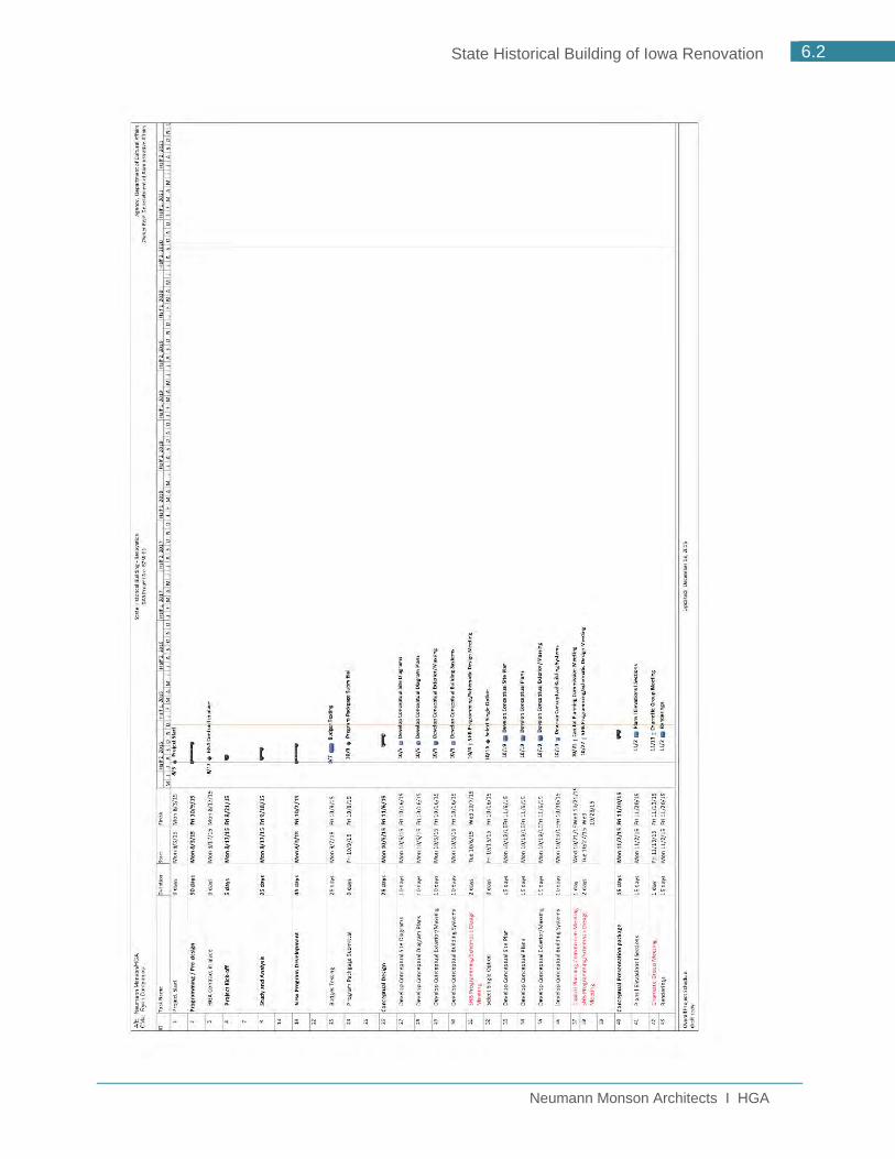
Neumann Monson Architects I HGA
6.2 State Historical Building of Iowa Renovation

Neumann Monson Architects I HGA
6.3 State Historical Building of Iowa Renovation

Neumann Monson Architects I HGA
6.4 State Historical Building of Iowa Renovation

Neumann Monson Architects I HGA
6.5 State Historical Building of Iowa Renovation
6.3 Project Budget and Cash Flow INTRODUCTION
The following documents were prepared by Ryan Companies working closely with the Neumann Monson/HGA design team, DCA and DAS and include
An Overall Project Budget Overall Cash Flow scenario for a five-year appropriation with funding source
breakdown Exhibit and Collections Budget identifying three funding levels

Neumann Monson Architects I HGA
6.6 State Historical Building of Iowa Renovation

Neumann Monson Architects I HGA
6.7 State Historical Building of Iowa Renovation

Neumann Monson Architects I HGA
6.8 State Historical Building of Iowa Renovation

Neumann Monson Architects I HGA
6.9 State Historical Building of Iowa Renovation
6.4 Project Cost Model
PROJECT COST MODEL
A detailed project cost model was prepared by Ryan Companies from drawings and narratives received from the Neumann Monson/HGA design team. The detailed cost model follows and represents a building construction cost of $49,963,656 and a building project cost of $57,211,584.
SCOPE NARRATIVE
To supplement the detailed project cost model, Ryan Companies prepared a scope narrative to document the scope that is included as well as excluded from the cost model. Substructure
Install new concrete footings and foundation wall for the new east end of the basement at grid line 11
Install new concrete foundations for elevator and stairs to the basement from lobby Install new concrete equipment pads in the basement for the new mechanical
equipment Structure
Install new steel column, framing, and metal deck for the infill additions shown on the concept plans (maintaining a 30’ x 30’ bay spacing)
Install concrete flooring over metal deck on the infill additions on 2nd and 3rd levels Install new steel columns, framing, and metal deck for the atrium addition (30’
addition to the east of grid line 7) Exteriors
Remove existing granite panels on the building that remains (west of grid line 7) Install new vapor barrier, insulation and exterior wall material assembly to meet code
requirements (basis of pricing is a metal panel system) Furnish and install new curtainwall system at the new atrium addition and as shown
on the concept elevations Remove and replace existing ballasted roof with a new adhered EPDM roof
Interiors
Furnish and install new architectural stairs from basement to lobby and from lobby to third floor
Furnish and install new stair from the third floor balcony to the ground level on the southwest corner of the building
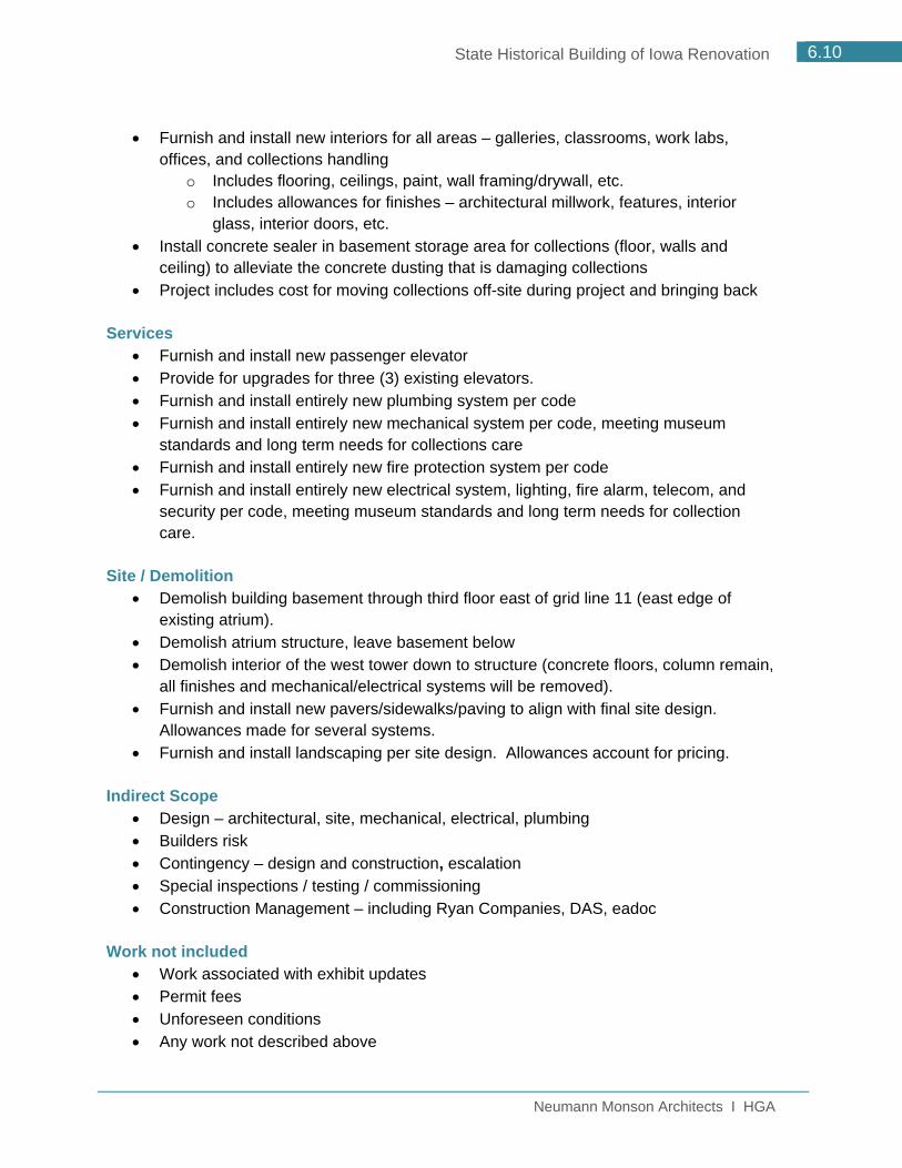
Neumann Monson Architects I HGA
6.10 State Historical Building of Iowa Renovation
Furnish and install new interiors for all areas – galleries, classrooms, work labs, offices, and collections handling
o Includes flooring, ceilings, paint, wall framing/drywall, etc. o Includes allowances for finishes – architectural millwork, features, interior
glass, interior doors, etc. Install concrete sealer in basement storage area for collections (floor, walls and
ceiling) to alleviate the concrete dusting that is damaging collections Project includes cost for moving collections off-site during project and bringing back
Services
Furnish and install new passenger elevator Provide for upgrades for three (3) existing elevators. Furnish and install entirely new plumbing system per code Furnish and install entirely new mechanical system per code, meeting museum
standards and long term needs for collections care Furnish and install entirely new fire protection system per code Furnish and install entirely new electrical system, lighting, fire alarm, telecom, and
security per code, meeting museum standards and long term needs for collection care.
Site / Demolition
Demolish building basement through third floor east of grid line 11 (east edge of existing atrium).
Demolish atrium structure, leave basement below Demolish interior of the west tower down to structure (concrete floors, column remain,
all finishes and mechanical/electrical systems will be removed). Furnish and install new pavers/sidewalks/paving to align with final site design.
Allowances made for several systems. Furnish and install landscaping per site design. Allowances account for pricing.
Indirect Scope
Design – architectural, site, mechanical, electrical, plumbing Builders risk Contingency – design and construction, escalation Special inspections / testing / commissioning Construction Management – including Ryan Companies, DAS, eadoc
Work not included
Work associated with exhibit updates Permit fees Unforeseen conditions Any work not described above

Neumann Monson Architects I HGA
6.11 State Historical Building of Iowa Renovation

Neumann Monson Architects I HGA
6.12 State Historical Building of Iowa Renovation

Neumann Monson Architects I HGA
State Historical Building of Iowa Renovation
7.1 PARTICIPANTS
7.2 CONTACT INFORMATION
7.3 DCA MISSION
7.4 DEPARTMENT BENCHMARKING
7.5 MUSEUM CASE STUDIES
7.6 AREA & OPERATIONAL COMPARISONS
7.7 IOWA CULTURAL INSTITUTION COMPARISONS
APPENDIX 7.0


Neumann Monson Architects I HGA
7.1 State Historical Building of Iowa Renovation
7.1 Participants This report is based on information provided by and conversations with the Department of Cultural Affairs, the Department of Administrative Services and their associates. The DCA Team for this project included:
Mary Cownie, Director, Department of Cultural Affairs Chris Kramer, Deputy Director, Department of Cultural Affairs Susan Kloewer, Administrator, State Historical Society of Iowa Steve King, Deputy State Historic Preservation Officer
Input and Support was provided by:
Charlee Cross, Chief Operating Officer, General Services Enterprise Josh Herman, LEED AP BD&C, Department of Administrative Services, Josh Miltenberger, LEED AP, Ryan Companies US, Inc, Construction Manager
Additional DCA staff and community stakeholders were also involved in this process. The project team at Neumann Monson Architects and HGA Architects and Engineers included:
Channing Swanson, AIA, LEED AP, Neumann Monson Architects, Principal Brian Warthen, AIA, LEED AP, Neumann Monson Architects, Project Manager Roxanne Nelson, AIA, LEED AP, HGA Architects and Engineers, Principal Loren Ahles, FAIA, NCARB, HGA Architects and Engineers, Museum Designer Gary Reetz, FAIA, HGA Architects and Engineers, Museum Expert Rebecca L. Krull Kraling, AIA, LEED AP, HGA Architects and Engineers, Project
Manager, Programmer Mario Gandelsonas, FAIA, Agrest + Gandelsonas, Principal, Urban Design
7.2 Contact Information For inquiries regarding this report contact: Chris Kramer, Deputy Director, Department of Cultural Affairs Iowa Department of Cultural Affairs 600 East Locust Street Des Moines, IA 50319 Phone: 515.281.5111 E-mail: [email protected]


Neumann Monson Architects I HGA
7.2 State Historical Building of Iowa Renovation
7.3 DCA Mission MISSION
We empower Iowa to build and sustain culturally vibrant communities by connecting Iowans to the people, places and points of pride that define our state.
VISION
Iowa is recognized as a state that fosters creativity and serves as a catalyst for innovation where the stories of Iowa are preserved and communicated to connect past, present and future generations.
MANDATE
The Iowa Department of Cultural Affairs:
Preserves and promotes Iowa’s collective heritage and unique sense of place Cultivates creativity, participation and learning in the arts Engages diverse statewide audiences through education initiatives, exhibitions and
public programs Provides tools, resources and knowledge to promote networking, collaboration and
best practices to nurture cultural leadership Invests in people and projects that foster economic growth and enhance the cultural
identity of local communities
VALUES
Responsiveness: We believe our priorities and programs should be adaptable, reflecting and respecting the evolving needs of Iowans.
Community: We believe culture at its root is a shared experience and we seek to foster relationships among people with everything we do.
Creativity: We believe that encouraging new ideas, approaches and fresh thinking are necessary for Iowa and our organization.
Collaboration: We believe partnership is essential to achieving greater impact, relevance and sustainability for our organization and our state.
Ingenuity: We believe in making the best use of the resources that we have, including space, time, expertise and dollars.
Stewardship: We believe it is our responsibility to preserve Iowa’s cultural legacy and resources


Neumann Monson Architects I HGA
7.3 State Historical Building of Iowa Renovation
7.4 Department Benchmarking Benchmarking is a way to check and validate assumptions against industry best practices and peer institutions. Lord Cultural Resources was previously engaged by DCA and DAS to do planning and research, including benchmarking of like functions across the 50 states. Some of the information included in this report is a result of their research and findings, while additional information was added based on HGA’s experience with similar cultural institutions and information provided by DCA.
ORGANIZATIONAL STRUCTURE
The Iowa DCA currently manages the following basic functional areas:
State Historical Society of Iowa o State Historical Museum o State Historic Preservation Office o State Archives, Records and Research Centers o Historic Sites
Produce Iowa Iowa Arts Council
It should be noted that Iowa is the only state to consolidate all these functional areas under one umbrella. (Source: Lord Report 2015 Master Planning Overview- page 9) STATE MUSEUMS
Of the 40 state flagship museums, only three, including Iowa, are within a cultural resources department.
STATE HISTORIC PRESERVATION OFFICE
The State Historic Preservation Office is the only program out of the six managed by DCA that is federally mandated. Just 20% of SHPO’s are located within a cultural resources department similar to the Iowa DCA.
STATE ARCHIVES, RECORDS AND HISTORICAL LIBRARIES
Of the states, like Iowa, that manage their archive and records programs jointly, 43% of those are managed by a cultural heritage or education department like Iowa’s DCA.


Neumann Monson Architects I HGA
7.4 State Historical Building of Iowa Renovation
7.5 Museum Case Studies CASE STUDY MUSEUMS
While working on developing the space program for the SHB Renovation, benchmarking was done to put the SHB into context with other similar institutions. Lord Cultural Resources made a presentation to DCA in March of 2015 that compared the following five museums as a case study to aid DCA in understanding how similar institutions compare to their own, four of which are State Historical Museums:
Minnesota History Center Natural History Museum of Utah North Carolina Museum of History Ohio History Center Witte Museum
The criteria used to select the case study museums were informed by the state museum key trend and implications presented in the Research Report completed by Lord Cultural Resources in June 2014. The case study compared the five museums in the following categories:
Attendance Facilities Expenses Revenues
All of the information described below is from the Lord Cultural Resources presentation from March 2015, unless noted otherwise.

Neumann Monson Architects I HGA
7.5 State Historical Building of Iowa Renovation
ATTENDANCE
Annual attendance for the case study museums in 2013 follows:
Minnesota Utah North Carolina Ohio Witte Average 2013 Annual Attendance
253,770 247,453 288,800 360,556 379,111 305,938
Of the case study museums, Minnesota, Utah, Ohio and the Witte charge for admission to the museum. Admission prices range from $8.00 to $11.00 for adults and all offer discounts for seniors and children. Currently admission to the State Historical Museum of Iowa is free of charge.
STATE HISTORICAL SOCIETY OF IOWA ENGAGEMENT Visitation FY2013 FY2014 FY2015
Museum 39,426 39,117 41,857
Museum + DCA Events (includes Educational Programs)
42,144 48,341 48,798
Museum Attendance TOTAL 81,570 87,458 90,655
Research Center (Des Moines) 5,106 4,621 3,200
Research Center (Iowa City) 3,106 3,267 3,200
State Historic Sites 37,583 43,885 50,187
Total SHB 127,365 139,231 147,242
FACILITIES Facility square footage for the total facility as well as other key components of the space program were also evaluated in the Case Study presentation. The table below identifies each case study museum’s total facility square footage as well as space accessed by the public and part of the visitor experience: exhibits, theater/auditorium, classrooms, and research/library functions. Institution Exhibit
Space SF Theater/
Auditorium SF Classroom/ Activities SF
Research/ Library SF
Other SF* Total Facility SF
Minnesota 41,379 5,384 7,519 20,887 403,907 479,076 Utah 42,500 n/a 7,104 6,657 106,739 163,000 North Carolina 55,000 41,000 2,200 900 74,900 174,000 Ohio 55,000 3,160 1,980 5,200 145,840 211,180 Witte 40,000 n/a 500 7,000 129,900 177,400 Average 46,776 16,515 3,861 8,129 172,257 240,931
*Other reported square footage included gift shop, food, administrative, storage, gardens, preservation and fabrication.

Neumann Monson Architects I HGA
7.6 State Historical Building of Iowa Renovation
EXPENSES
Program expenses for each of the case study museums were also evaluated. The average expense total for the case study museums was $20,956,654. Note that the Natural History Museum of Utah was omitted from the expense summary due to its ties with the University of Utah and hence embedded expenditures within the University. Annual expense totals are indicated in the table below. Minnesota Utah North Carolina Ohio Witte Average Annual Expenses
$54,769,000 (FY 2014)
n/a $646,724 (2014)
$20,100,344 (FY 2013)
$8,310,549 (FY 2013)
$20,956,654
Iowa’s annual expenses for FY 2015 for the museum only were $2,203,188. Details for each of the following categories of expenses can be found in the presentation:
Program Expenses o Education o Exhibitions, site operations, store, other
Support Expenses o Fundraising/development o Management & general
Capital Costs o Capital expenditures

Neumann Monson Architects I HGA
7.7 State Historical Building of Iowa Renovation
REVENUES
Revenues for each of the case study museums were also evaluated. The average revenue total for the case study museums was $18,213,018.
A summary of the revenues and their primary sources for each of the case study museums is included in the table below. Minnesota Utah North
Carolina Ohio Witte Average
Earned $2,385,000 $2,310,062 $595,871 $1,665,855 $3,947,954 $2,854,081 Contributed $6,295,000 $1,687,387 $385,100 $1,500,074 $13,384,620 $5,159,964 Government $33,513,000 $2,102,816 $0 $13,824,444 $484,780 $17,150,654 Investment $915,000 $25,522 $36,701 $0 $425,108 $701,166
TOTAL 43,108,000 6,125,787 1,017,672 16,990,373 18,242,462 Other $1,909,000 $1,220,593 $0 $2,368,167 $83,036 $1,395,199
GRAND TOTAL
$45,017,000 $7,346,380 $1,107,672 $19,358,540 $18,325,498 $18,213,018
Iowa’s revenues for FY 2015 for the museum only were $2,277,005. Details for each of the following categories of revenues can be found in the presentation:
Earned o Admissions o Retail (gross) o Food Service (gross, includes rentals) o Rentals o Memberships o Public Programs o Other self-generated (parking)
Contributed o Individual/corporate support o Foundation support o Fundraising events
Government o Local government support (unrestricted) o State government support o Federal government support
Investment o Endowment revenue o Released from restricted investment income
Other (contracts, library fees, publications, in-kind, etc.)

Neumann Monson Architects I HGA
7.8 State Historical Building of Iowa Renovation
7.6 Area and Operational Comparisons
To expand on the research that Lord Cultural Resources completed for the DCA, HGA provided some additional benchmarking data comparing the current SHB and the proposed SHB to State Historical Museums that HGA has designed or is designing; the Minnesota History Center, the North Dakota Heritage Center and the Tennessee State History Museum. The following spreadsheet outlines both square footages of similar spaces in each facility and has drawn additional budgetary & operational information requested by the DCA as it was available and/or applicable. The budgetary and operational information includes the following:
Exhibit Design & Construction Annual Attendance Governing Department Annual Operating Budget Museum Budget Museum Foundation Budget Archive Budget Total Department Staff Museum Staff
In summary, the spreadsheet shows us the following:
In terms of percentage of exhibit and collections space to overall building size, the renovated SHB falls in the middle of the range of the comparable institutions.
In terms of other Visitor and Program Amenities, the renovated SHB is well in line with the comparable institutions
The widest range of variation between the institutions is within the space dedicated to Archive and Collections which is a direct reflection of each state’s collection and approach to its location. For example, the Tennessee State collection is not located in the same building as the museum.
One substantial difference between Iowa and the other states is in the category of funding and staffing levels. Iowa falls significantly lower than the other comparable institutions.

Neumann Monson Architects I HGA
7.9 State Historical Building of Iowa Renovation

Neumann Monson Architects I HGA
7.10 State Historical Building of Iowa Renovation
MUSEUM PLANNING STANDARDS
In addition to the information gleaned from the specific facility comparisons, HGA provided some additional benchmarking information based on HGA research regarding museum planning standards and staffing/budget standards as related to exhibit square footage as described by the Association of Science and Technology Centers (ASTC). Museum Planning Standards:
All Museums
Visitor Services 15%
Gallery/Exhibition Spaces 50%
Conservation/Collections Storage 20%
Education/Resource Areas 10%
Administrative/Support 5%
100%
Science Museums
Visitor Services 20%
Gallery/Exhibition Spaces 60%
Conservation/Collections Storage 10%
Education/Resource Areas 5%
Administrative/Support 5%
100%
Collection Museums
Visitor Services 15%
Gallery/Exhibition Spaces 35%
Conservation/Collections Storage 30%
Education/Resource Areas 15%
Administrative/Support 5%
100%
State Historical Building of Iowa Renovation
Visitor Services 19%
Gallery/Exhibition Spaces 24%
Conservation/Collections Storage 37%
Education/Resource Areas 10%
Administrative/Support 10%
100%
Of the museum types HGA has researched, the SHB falls into the Collection Museums category. When comparing the typical space allotment percentages for a Collection Museum and that of the SHB Renovation, there are a few key differences, most notably in the Visitor

Neumann Monson Architects I HGA
7.11 State Historical Building of Iowa Renovation
Services and Administrative Support Categories. This corresponds to two key things that make the SHB different from a typical collection museum; the SHB is intended to be the Iowa Visitor Center and gateway to the Capitol Complex, and the SHB houses an entire governmental department, not just museum administration. ASTC EXHIBIT SIZE / STAFF / BUDGET COMPARISONS
The Association of Science and Technology Centers (ASTC) has published some statistics that compare building square footage and exhibit square footage to annual attendance, staff size and expenses. This helps provide a framework within which DCA can understand where they fit and can help plan where they need to go in the future in order to provide a sustainable exhibit rotation program. ASTC Statistics from the ASTC 2008 Sourcebook of Statistics & Analysis:
ASTC Statistics* Very Small Small Center Medium Center Large Center
Square footage 12,000 sf 52,135 sf 88,000 sf 245,000 sf
Exhibits 6,000 sf 18,742 sf 34,900 sf 78,500 sf
Annual Attendance 45,278 112,994 230,374 559,189
FTE staff 9 27.5 58 138
Volunteers 50 114 160.5 351
Expenses $637,787 $1,881,767 $4,812,000 $11,280,684 *statistics represent the median values

Neumann Monson Architects I HGA
7.12 State Historical Building of Iowa Renovation
7.7 Iowa Cultural Institution Comparisons The DCA explored how the State Historical Museum compares to other Iowa cultural institutions in terms of operating budgets, total annual attendance and annual youth attendance. The State Historical Museum’s annual operating budget was $2,203,188 for FY 2015. The State Historical Museum’s annual attendance for FY 2015 was 90,655 which includes 41,857 museum only visits and 48,798 museum plus event and/or education program visits. See page 7.5 of the Appendix for additional detail regarding annual attendance breakdowns at the SHB. The State Historical Museum’s annual youth attendance for 2015 was 13,433. Institution Operating
Budget Total Annual Attendance
Annual Youth Attendance
Science Center of Iowa $5,157,360 339,264 237,484 Mississippi River Museum $3,969,328 186,000 81,000 Putnam Museum $3,184,639 133,013 61,896 Sioux City Public Museum $967,808 60,020 30,010 Family Museum $1,900,000 5,737 3,328 Grout Museum $1,239,806 129,299 81,342