task 02 schematic design report...foundation design recommendations for the proposed explore and...
TRANSCRIPT

SS OO UU TT HH AA UU DD BB LL OO CC KK RR EE DD EE VV EE LL OO PP MM EE NN TT II EERRIIEE CCAANNAALL HHAARRBBOORR DDEEVVEELLOOPPMMEENNTT CCOORRPPOORRAATTIIOONN
6395 West Quaker Street I Orchard Park, New York 14127 I 716 662 2200 Page 15 of 54
TASK 02 – Schematic Design Report
I s s u e d : D e c e m b e r 1 5 , 2 0 1 5
2. Foundation Evaluation and Design Recommendation Report

November 16, 2015 Project 1507920 Mr. Donald E. Aubrecht Fontanese Folts Aubrecht Ernst Architects, P.C. 6395 West Quaker St. Orchard Park, New York 14127 Dear Mr. Aubrecht: Re: Foundation Evaluation and Design Recommendations
Proposed Canalside Development Buffalo, New York
The purpose of this letter is to present the results of our existing foundation evaluation and our foundation design recommendations for the proposed Explore and More Children’s Museum, which will be located at the South Block of the Canalside Development at the former Buffalo Memorial Auditorium Site. These services were performed in accordance with the signed proposal “Foundation Evaluation and Design Scoping Services,” dated June 30, 2015.
Background Information
We understand that Fontanese Folts Aubrecht Ernst Architects, P.C. (FFAE) is working with the Erie Canal Harbor Development Corporation (ECHDC) to develop and construct the Explore and More Children’s Museum at the South Block of the former Buffalo Memorial Auditorium Site in Buffalo, New York. The proposed museum is bound by Lloyd Street on the east, a pedestrian plaza on the south, and the Erie Canal replica on the north and west. The central portion of the proposed building footprint overlaps the sub-basement of the former auditorium, which will remain in place. The sub-basement floor is located at approximately El. 566. The ground surface along the walkways and roads surrounding the site ranges from El. 580.4 to El. 590.5. All elevations are in feet and are referenced to the City of Buffalo Datum.
We understand that the sub-basement walls and floor will be incorporated into the structure of the Explore and More Children’s Museum. We were provided with the original design drawings for the Buffalo Memorial Auditorium dated 1939, which includes a foundation plan and schedule. The former auditorium structure was supported on driven H-piles, end bearing on bedrock. Subsurface explorations were performed by Empire Geo-Services in 2009, and unconfined compressive strength testing was done on five limestone bedrock core samples. The testing indicated that the limestone has an unconfined compressive strength ranging from 9,460 psi to 19,630 psi with an average of 15,675 psi. Based on these results, the limestone bedrock provides a suitable bearing stratum for the driven pile foundations and the H-Piles can be assumed to derive their capacity predominantly through end bearing.
In 2009 Empire Geo-Services performed a pile extraction investigation to evaluate the condition of the existing piles with regard to potential corrosion and to develop appropriate capacities for re-use of the piles. Two piles were extracted from outside the existing sub-basement area. Based on the measurements, the piles corresponded to an HP 8x36 pile section which was in agreement
GEI Consultants, Inc., P.C. 400 Unicorn Park Drive, Woburn, MA 01801
781.721.4000 fax: 781.721.4073
www.geiconsultants.com
Consulting
Engineers and
Scientists

Mr. Donald E. Aubrecht -2- November 16, 2015
with the H8x36 pile specified in the design drawings. The piles had no indication of significant corrosion or section loss. Based on historical information on structural steel used in 1939, Empire Geo-Services concluded that the steel grade likely used for the building was A9 steel which is reported to have a yield strength of about 33 ksi. Empire Geo-Services recommended pile capacities using 25% of the presumed yield strength and assuming a 5% reduction in cross-sectional area to account for possible corrosion and section loss.
In 2012, Atlantic Testing Laboratories, Limited performed high strain dynamic tests on two existing H-piles outside the subbasement area. Results of the tests were analyzed using the Case Pile Wave Analysis Program (CAPWAP). Based on the CAPWAP results, the two existing piles tested had ultimate geotechnical capacities of 690 and 826 kips.
Foundation plans for the proposed structure include reuse of the existing foundations and installation of new foundations as needed. A portion of the capacity of the existing foundations is taken up by the loads of the existing subbasement, and the remaining capacity may be used to support additional museum loads.
Laboratory Testing on Samples from Existing Piles
We engaged Simpson Gumpertz and Heger (SGH) to do a metallurgical analysis of H-Piles from the Buffalo Memorial Auditorium Site. They performed the following tests on two H-Pile sections extracted north of the sub-basement area:
1. Chemical Composition Analysis
2. Microstructure Evaluation
3. Charpy Impact Test (to evaluate toughness of the samples)
Based on the results of the laboratory testing, SGH concluded that:
1. Based on the chemical composition analysis and microstructure evaluation, the piles are suitable to structural welding and meet the requirements to be prequalified according to AWS D1.1.
2. The Charpy impact energy indicates that the material has adequate resistance to fracture at ambient temperatures.
A letter from SGH summarizing the laboratory test results in detail is included as Attachment A to this letter.
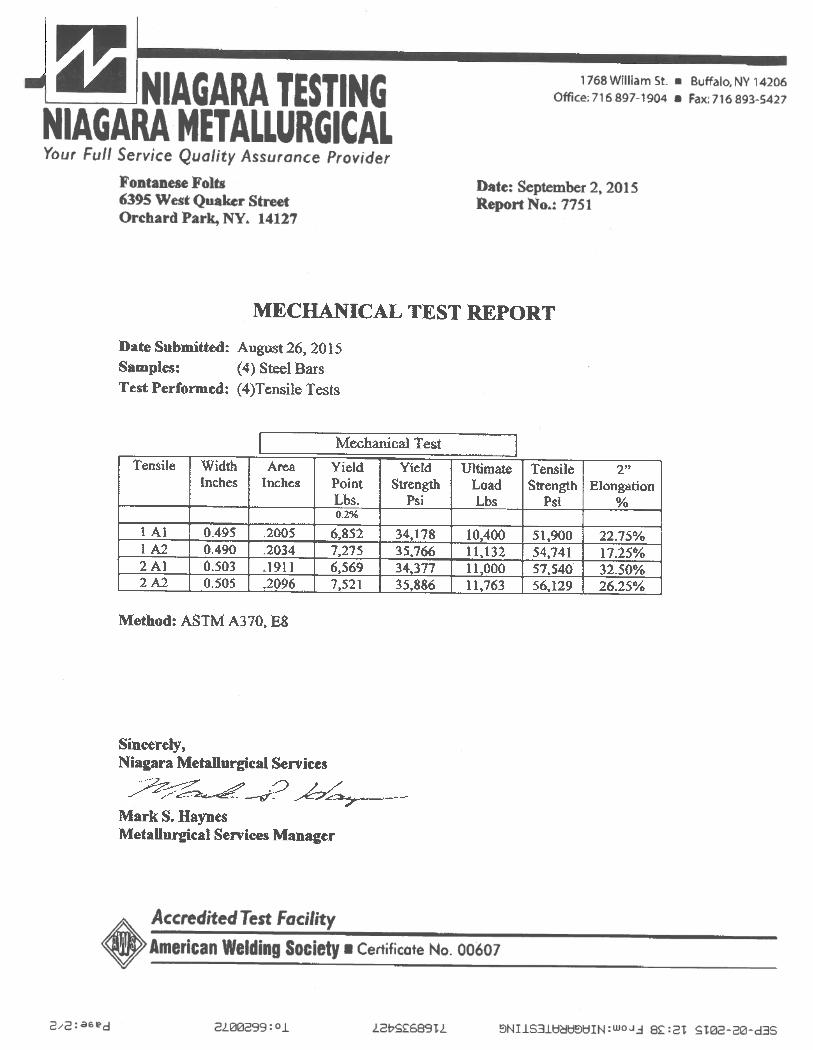
FFAE engaged Niagara Testing to perform tensile strength tests on the two H-Pile samples to evaluate the yield strength of the steel. The results of the testing confirmed that the yield strength for the steel is about 33 ksi. The results of the testing are included as Attachment B.
Evaluation of the Capacity of the Existing Piles
We evaluated the total and remaining capacity of the existing steel H-piles in the subbasement area. Our evaluation was based on existing information as well as the results of the laboratory testing described above. We assumed individual pile allowable stresses could be taken as 50% of the yield strength, per the New York State Building Code Section 1808.2.10. This provision applies if a geotechnical investigation has been performed at the site and load tests have been performed on the piles, both of which apply at the Canalside site. We reduced the pile section areas by 5% to account for possible corrosion. The total capacity and the remaining capacity (after subtracting the existing subbasement loads) for each existing pile group are summarized in Table 1.

Mr. Donald E. Aubrecht -3- November 16, 2015
Preliminary Design and Recommendations for Micropiles
The loads for the Explore and More Children’s Museum that are not supported on existing steel H-piles may be supported on drilled micropiles. Some of these micropiles will be located outside the existing subbasement, and some may be drilled through the existing subbasement floor slab.
Preliminary Micropile Design
The final building loads and pile locations are not known at this time. We performed preliminary design of micropiles for a range of column loads. The load range was selected based on preliminary loads for several building scenarios provided by Ravi Engineering and Land Surveying, P.C. (Ravi) in June 2015. Our preliminary design is for 9 5/8-inch-diameter micropiles with a 0.545-inch-thick steel casing. We provided an additional preliminary design for more lightly loaded columns using 7-inch-diameter micropiles with a 0.408-inch-thick steel casing. All micropiles were designed with a single center reinforcing bar. Piles are assumed to be socketed into the limestone bedrock and derive all of their geotechnical capacity from skin friction in the bedrock. We assumed an average bond strength for limestone bedrock based on Table 5-2 in “Micropile Design and Construction Guidelines FHWA SA-97-070.” The number of piles per pile cap, the size of the center bar and the length of the rock socket were varied to accommodate each load condition. The results of the preliminary micropile design for 9 5/8-inch-diameter micropiles and 7-inch-diameter micropiles are presented in Tables 2 and 3, respectively. The preliminary design assumes that lateral loads on the piles will be relatively low. We will consider lateral loads on the piles in our final design.
General Micropile Recommendations
Micropiles will be installed by drilling a steel casing, in sections, to the top of bedrock. The drilling will be performed using the duplex method in which the drill fluid is pumped downward through drill rods inside the casing and returns upward inside the casing. The micropile will then be drilled below the casing to the required rock socket depth, to provide a direct bond between grout and limestone bedrock. When the micropile reaches the desired depth, a steel reinforcement bar will be lowered inside the casing and will extend the full depth of the micropile. The micropile will then be filled with cement grout using a tremie method.
Micropiles will be connected to the above-grade structure using reinforced concrete pile caps. The bottom of the pile caps will be installed a minimum of 4 feet below final grade for frost protection.
Final design of all micropiles will be in accordance with the Section 1810.8 of the 2010 Building Code of New York State. Based on correspondence with New York State Building Code personnel, we understand that a load test is not required for micropiles at the project location if an experienced geotechnical engineer confirms that the design is conservative. It is therefore likely that no load test will be required, but this will need to be confirmed by local building officials.
We understand the site is classified as Seismic Site Class “D”, and structural design of the micropiles and pile caps will take this classification into consideration per Section 1808.2.23.2 of the Building Code.
In accordance with the Building Code, observation and documentation are required during foundation construction. These observations should be made by a registered design professional in accordance with Section 1704.8 of the Building Code.

Mr. Donald E. Aubrecht -4- November 16, 2015
Recommendations for Micropiles Installed within the Subbasement Footprint
Micropiles installed within the footprint of the subbasement will require special consideration. Due to access constraints, we assume it will be necessary to install these micropiles through the roof of the subbasement. This will also allow the piles to be drilled and grouted from a working elevation located above the groundwater level. Micropile locations will need to be selected to avoid compromising the structural integrity of the roof. The penetrations through the roof will need to be evaluated by a structural engineer to evaluate whether temporary support of the roof is needed, and repairs to the roof will be necessary once micropile installation is complete.
Based on the 1939 drawings of the auditorium, and information from the Sub-Basement Floor Slab Investigation performed by Empire Geo Services, Inc. in 2009, we understand that the subbasement floor slab is a multilayer system. The base of the slab consists of approximately 3 inches of concrete overlain by a waterproofing membrane. An inverted waffle slab sits on the base slab. The waffle slab consists of a 6-inch-thick base with 1.7-foot-high ribs. The spaces between the ribs are filled with unreinforced concrete. An approximately 5-inch-thick floor slab sits on top of the waffle slab, spanning over the ribs. This original floor slab is overlain by a 4-inch-thick layer of gravel and a 4-inch-thick new floor slab. We understand the gravel and new floor slab were installed in 2014, and a sub-floor drainage system was installed in the gravel at that time.
If the ribs of the waffle slab can be mapped accurately, we recommend that the micropiles be laid out such that they penetrate the space between the ribs and not the ribs themselves, so that the structural integrity of the slab is maintained to the extent possible.
Our preliminary design concept involves installation of the micropiles inside a temporary standpipe that extends from the top of the original floor slab to the subbasement roof. The standpipe allows the drilling operation to maintain enough hydrostatic head on the drilling fluid to counteract the groundwater uplift pressure below the floor slab. The bottom of the standpipe will have a flange that will be bolted to the top of the lower floor slab (below the gravel layer). A gasket will be installed beneath the flange to provide a watertight seal. The micropile will then be installed through the standpipe from the subbasement roof.
The micropile will be drilled to the top of rock using the micropile casing, and the rock socket will be drilled beyond the casing as required. After installation of the micropile is complete, the annulus between the micropile casing and the standpipe will be grouted by means of grout ports installed in the standpipe. The micropile will be cut off below the top of the pile cap and both the micropile casing and the bottom of the standpipe will remain in place below the cutoff. The gasket beneath the flange on the standpipe should provide a seal that will significantly limit seepage through the micropile penetrations. Any moisture that seeps beyond the gasket will go into the existing subfloor drainage system.
To minimize disturbance to the existing floor system, we recommend that new pile caps be placed above the existing floor slab. We understand this configuration is acceptable to ECHDC.
A sketch showing the preliminary concept for micropile installation is attached (Fig. 1).
Conclusions and Limitations
Based on the results of this preliminary study, the existing steel H-piles within the subbasement of the former Buffalo Memorial Auditorium have significant capacity that can be used to support a portion of the loads of the new Explore and More Children’s Museum. The remaining loads may be supported using drilled micropiles located both within and outside the subbasement


GEI Consultants, Inc., P.C.
Tables

GEI Consultants, Inc., P.C.Project 1507920
November 2015 M:\PROJECT\2015\1507920 Canalside\Tables.xlsx
Table 1. Existing Pile CapacityFoundation Evaluation and Design RecommendationsProposed Canalside DevelopmentBuffalo, New York
Cross-Sectional
Area
Individual Pile
Capacity1,4
Group Pile
Capacity
Existing Structure
load5
Remaining Capacity
(in2) (kips) (kips) (kips) (kips)B44a PI 2 8H36 HP 8x36 10.6 166 332 271 62B44 PI 2 8H36 HP 8x36 10.6 166 332 226 106E48 P4 3 8H36 HP 8x36 10.6 166 498 249 250E47 P4 3 8H36 HP 8x36 10.6 166 498 403 96F44 P4 3 8H36 HP 8x36 10.6 166 498 175 323E44 P4 3 8H36 HP 8x36 10.6 166 498 318 181
B44b P4 3 8H36 HP 8x36 10.6 166 498 419 80F43 P4 3 8H36 HP 8x36 10.6 166 498 106 393F47 P5 3 10H44 HP 10x42 12.4 194 583 129 454
BB45 P5 3 10H44 HP 10x42 12.4 194 583 437 146A44a P5 3 10H44 HP 10x42 12.4 194 583 335 248F48 P6 3 12H53 HP 12x53 15.5 243 729 159 570B47 P6 3 12H53 HP 12x53 15.5 243 729 343 386B46 P6 3 12H53 HP 12x53 15.5 243 729 376 353F45 P6 3 12H53 HP 12x53 15.5 243 729 336 393C44 P6 3 12H53 HP 12x53 15.5 243 729 460 269
BB44 P6 3 12H53 HP 12x53 15.5 243 729 385 344F46 P7 4 10H44 HP 10x42 12.4 194 777 392 386E43 P7 4 10H44 HP 10x42 12.4 194 777 313 464C47 P8 4 12H53 HP 12x53 15.5 243 972 485 487B45 P8 4 12H53 HP 12x53 15.5 243 972 417 554C45 P8 4 12H53 HP 12x53 15.5 243 972 590 382C48 P9 4 14H73 HP 14x73 21.4 335 1342 364 978C46 P9 4 14H73 HP 14x73 21.4 335 1342 700 642A44 P9 4 14H73 HP 14x73 21.4 335 1342 278 1063B43 P9 4 14H73 HP 14x73 21.4 335 1342 200 1142
BB44a P10 5 14H73 HP 14x73 21.4 335 1677 344 1333A40 P10 5 14H73 HP 14x73 21.4 335 1677 392 1285A43 P10 5 14H73 HP 14x73 21.4 335 1677 250 1428A46 P12 6 14H73 HP 14x73 21.4 335 2013 281 1732A45 P12 6 14H73 HP 14x73 21.4 335 2013 684 1328
A44b P14 7 14H73 HP 14x73 21.4 335 2348 682 1666
Notes:1. Steel yield strength of 33ksi was verified by tensile strength tests on extracted piles performed by Niagara Testing in August 2015.
2. Pile cap locations as per original Memorial Auditorium drawings.
3. Corresponding pile size based on the Pile Extraction Investigation Report (2009) by Empire Geo Services, Inc.
5. Existing structure loads provided by Ravi Engineering and Land Surveying, P.C. Building Code (with geotechnical investigation and load test). Pile area reduced by 5% to account for possible corrosion.
Pile Cap Location2
Pile Group
No. Piles in Group
Historic Pile Size
Corresponding Pile Size3
4. Individual pile capacity is taken as 50% of yield strength (16.5 ksi) as allowed by Sect. 1808.2.10 of the New York State

GEI Consultants, Inc., P.C.Project 1507920
November 2015 M:\PROJECT\2015\1507920 Canalside\Tables.xlsx
Table 2. Preliminary Design with 9 5/8-inch-Diameter MicropilesFoundation Evaluation and Design RecommendationsProposed Canalside DevelopmentBuffalo, New York
Column Loads
Number of Piles OD Casing tw
Center Reinforcing Bar
Minimum Length of Rock
Socket(kips) (in) (in) (No.) (ft)100 3 9.625 0.545 8 3200 3 9.625 0.545 10 3300 3 9.625 0.545 10 3400 3 9.625 0.545 14 4500 3 9.625 0.545 18 5600 3 9.625 0.545 18 6700 4 9.625 0.545 18 5800 4 9.625 0.545 18 6900 5 9.625 0.545 18 51000 5 9.625 0.545 18 61100 6 9.625 0.545 18 61200 6 9.625 0.545 18 61300 7 9.625 0.545 18 61400 7 9.625 0.545 18 61500 8 9.625 0.545 18 61600 8 9.625 0.545 18 61700 9 9.625 0.545 18 61800 9 9.625 0.545 18 61900 10 9.625 0.545 18 62000 10 9.625 0.545 18 6

GEI Consultants, Inc., P.C.Project 1507920
November 2015 M:\PROJECT\2015\1507920 Canalside\Tables.xlsx
Table 3. Preliminary Design with 7-inch-Diameter MicropilesFoundation Evaluation and Design RecommendationsProposed Canalside DevelopmentBuffalo, New York
Column Loads
Number of Piles
OD Casing
twCenter
Reinforcing BarMinimum Length of Rock Socket
(kips) (in) (in) (No.) (ft)100 3 7 0.408 8 3200 4 7 0.408 8 3300 4 7 0.408 11 4400 5 7 0.408 11 4500 6 7 0.408 11 4600 6 7 0.408 14 4700 7 7 0.408 14 4800 8 7 0.408 14 4

GEI Consultants, Inc., P.C.
Figures

MICROPILE CASING
CENTER
REINFORCING BAR
STANDPIPE
WATERPROOFING
MEMBRANE
GROUT PORT
SLAB
WAFFLE SLAB
SLAB
GRAVEL
SLAB 4"
4"
5"
1'-8"
6"
3"
CONCRETE
FILL
GROUT
SLAB
GRAVEL
SLAB
BOLT
(TYP.)
GASKET
REINFORCED
CONCRETE
PILE CAP
EXTENDED TO ROOF
DURING PILE INSTALLATION
\\bos1v-fs02\ \\bos1v-fs02\PROJECTS\DATA\2015\1507920 Canalside Buffalo\Drawings\1507920_CDES_MPILE.dwg - 11/13/2015
Fig. 1
Concept Level Design
Proposed Canalside Development
Buffalo, New York
Fontanese Folts Aubrecht Ernst Architects, P.C.
Orchard Park, New York
MICROPILE CONCEPT
November 2015Project 1507920
Consultants
NOTE:
1. NOT TO SCALE. DIMENSIONS OF EXISTING SLAB
SYSTEM ARE APPROXIMATE.
2. FINAL CONDITION SHOWN. OUTER CASING MAY
BE THREADED TO ALLOW ATTACHMENT OF
SUFFICIENT CASING TO EXTEND ABOVE WATER
TABLE DURING DRILLING.

GEI Consultants, Inc., P.C.
Attachment A
SGH – Detailed Summary of Laboratory Test Results

6 October 2015
Ms. Mary NodineGEI Consultants, Inc.400 Unicorn Park DriveWoburn, MA 01801
Project 151425 – Metallurgical Analysis of Steel Piles at Hockey Arena, Buffalo, NY
Dear Ms. Nodine:
You asked us to conduct metallurgical analysis of steel piles from the above named project.This letter contains a summary of our findings.
1. INTRODUCTION
We understand that the hockey arena in Buffalo New York is currently undergoing renovation.The building dates from 1935, and contains steel piles which have suffered minor section lossfrom corrosion. Although there are no current plans to weld to these piles, you have asked us toreview the chemical composition, microstructure, and impact toughness of these piles to assesstheir structural integrity and suitability for structural welding.
2. LABORATORY ANALYSIS
We received two steel H-pile sections in our laboratory for analysis, labelled “1” and “2B.” Wewere not provided with any indication of the location of these piles in the building.
2.1 Chemical Composition Analysis
We conducted chemical composition analysis of the samples according to ASTM E350-12“Standard Test Methods for Chemical Analysis of Carbon Steel, Low-Alloy Steel, SiliconElectrical Steel, Ingot Iron, and Wrought Iron.” From these measurements, we calculated thecarbon equivalent according to AWS D1.1-2010 “Structural Welding Code.” The results arelisted in Table 1.
Table 1 – Chemical Composition of Samples (wt.%)
Element #1 #2B
Carbon 0.15 0.2
Manganese 0.55 0.69
Silicon 0.09 0.14
Nickel 0.03 0.05
Copper 0.03 0.03
Phosphorus 0.025 0.014
Sulfur 0.03 0.023
Carbon Equivalent 0.26 0.34

Ms. Mary Nodine – Project 151425 - 2 - 6 October 2015
2.2 Microstructure
We cut a section of each pile using a water-cooled abrasive cutting wheel for metallographicanalysis. We mounted these sections in a thermosetting resin, ground them using siliconcarbide paper to a finish of 1200 grit, then polished them using diamond paste to a finish of 1micron. We etched these sections using a 2% Nital solution and observed the microstructuresin an optical microscope.
We observed that the microstructures of both sample are uniform. Example micrographs areshown in Photos 1 to 2.
2.3 Charpy Testing
We conducted Charpy testing of each sample at ambient temperature according to ASTM E8-15“Standard Test Methods for Tension Testing of Metallic Materials,” and ASTM A370-14“Standard Test Methods and Definitions for Mechanical Testing of Steel Products,” using 2 in.long samples. The results are listed in Table 2.
Table 2 – Results of Charpy Testing
#1 #2B
Average ImpactToughness (ft-lb)
54 36
3. DISCUSSION
3.1 Composition, Microstructure, and Weldability
Both piles are manufactured from low carbon steels of similar composition, with a carboncontent varying from 0.15 to 0.20 wt.%. We calculated the carbon equivalent of these steels asvarying from 0.26 to 0.34 wt.%. A carbon equivalent of less than 0.4% indicates that the steel isreadily weldable without additional requirements of preheat, post weld heat treatment, or lowhydrogen electrodes.
The content of the impurity elements phosphorus and sulfur in these steels is acceptable, andmeets the requirements of ASTM A36-14 “Standard Specification for Carbon Structural Steel.”The microstructures of both piles are uniform without any excessive inclusions or other defects.
Therefore, these piles are suitable for structural welding to and are prequalified according toAWS D1.1.
3.2 Impact Toughness
The impact toughness at ambient temperature of these materials is adequate, as a Charpyimpact energy of greater than 20 ft-lb typically indicates good resistance to brittle fracture,structural integrity. However, these tests do not indicate the ductile to brittle transitiontemperature (DBTT), so additional impact tests are recommended if the piles are going to beexposed to low temperatures.

Ms. Mary Nodine – Project 151425 - 3 - 6 October 2015
4. CONCLUSIONS
The piles are suitable to structural welding and meet the requirements to beprequalified according to AWS D1.1
The Charpy impact energy results indicate that the material has adequate resistance tofracture at ambient temperature.
Sincerely yours,
William Konicki, P.E. Alan Humphreys PhDSenior Principal Senior Staff II MetallurgyNY License No. 087770I:\BOS\Projects\2015\151425.00-HCKY\WP\001AOHumphreys-L-151425.ras.docx

SGH Project 151425.00 / October 2015
Photo 1
Microstructure of Sample 1.
Photo 2
Microstructure of Sample 2B.

GEI Consultants, Inc., P.C.
Attachment B
Niagara Testing -- Tensile Strength Test Results