498_1
TRANSCRIPT

7/27/2019 498_1
http://slidepdf.com/reader/full/4981 1/9
Leonardo Torbidonie-mail: [email protected]
Aristide F. Massardoe-mail: [email protected]
Thermochemical Power Group,
Dipartimento di Macchine Sistemi Energetici e
Trasporti,
Universita di Genova,
Via Montallegro 1,
16145 Genova, Italia
Analytical Blade Row CoolingModel for Innovative Gas TurbineCycle Evaluations Supported bySemi-Empirical Air-Cooled BladeDataWith the objective of performing reliable innovative gas turbine cycle calculations, a new
procedure aimed at evaluating blade cooling performance is presented. This completeanalytical (convective and film) blade cooling modeling provides the coolant mass flowand pressure loss estimation, and is a useful tool in the field of innovative gas turbinecycle analysis, mainly when alternative fluids are considered. In this case, in fact, theconventional semi-empirical data based on the use of air as traditional coolant and working media are no longer suitable. So the analytical approach represents a way of
properly investigating alternative cooling methods and fluids. In the presented analysisthe effects of internal blade geometry on cooling performance are summarized by the Z
parameter, which also highly affects the coolant flow pressure losses. Since existing tech-nology represents a natural starting point for the assessment of Z, the model is able toautomatically estimate a proper value relying only on available semi-empirical datawhich were established for air-cooled gas turbine blades. When alternative fluids areconsidered, the same estimated value of Z is still maintained for the calculation, with theresult of investigating the performance of existing blade technology for novel operationalconditions. This represents an example of how the analytical approach, supported byconventional air-cooled blade semi-empirical data, appears as an innovative tool in theanalysis of novel gas turbine cycles. In fact, the simulation results for the cooled bladewere easily employed on the whole system level (gas turbine). DOI: 10.1115/1.1707030
Introduction
In a society where economic and low-polluting power produc-
tion has become of vital importance, the development of cheap,
new, and clean power plants is important. In such a scenario the
advent of the deregulated electricity market has reinforced the
quest for cheap, clean, reliable and efficient means of heat and
electric power generation.
This ongoing trend, which is very likely to continue and even
increase in the future, not only includes attempts to improve ex-
isting thermal cycles but also to develop new ones, most of which
consider alternative fluids and working media. In the field of
cycles based on the use of gas turbines, new solutions have been
proposed, such as: the humid air turbine cycle, 1,2 , the
SOFC-GT cycle, 3,4 , and the Matiant cycle, 5 . Moreover, the
realization of steam cooling in combined cycles is the main ap-
parent example of innovative design at a cycle level, 6 .
Another important aspect is that the step from the theoretical
analysis to the hardware demonstration of the new technologies
should require significant effort in research and technological de-
velopment, 7,8 and could comprise considerable risk and high
cost. This in turn means that it is uncertain how many and what
innovative gas turbine cycles will actually be turned into operat-
ing power plants. Hence, it is necessary to identify what cycles are
technically and economically interesting at an earlier stage, 2,9 .
A natural starting point for the hardware demonstration of an
innovative cycle should be existing gas turbine technology. There-fore, it is important to assess how existing gas turbines will oper-ate, adopting alternative coolants and working media which areoften of interest in innovative cycles.
The present paper deals with the problem of evaluating theinfluence of changing fluid composition on the analysis of theperformance of innovative gas turbine-based cycles, with the pur-pose of increasing the reliability of the results at the gas turbinesystem level.
A method for estimating the performance and the required tech-nological development only for convectively cooled vanes whichare operating in the presence of alternative media has been previ-ously proposed by the authors, 10 . In the present work, thismethod has been carefully revised and extended to include filmcooled blades too.
The adopted analytical approach allows the blade coolinganalysis in presence of alternative fluids to be obtained. At thesame time, the assessment of a few parameters through the use of the air cooled blade semi-empirical data not only should improvereliability, but also avoid the need of a large number of input data
mainly geometrical data necessary to run such an analytical cal-culation. This makes the model a worthwhile and user-friendlytool when blade cooling performance has to be evaluated at thegas turbine system level for the investigation of traditional andinnovative cycles.
Film Cooling Model
In a previous work, 10 , the authors have focused on the caseof convective blade cooling analysis. In the present work this pro-cedure has been carefully revised and extended to include film
Contributed by the International Gas Turbine Institute IGTI of THE AMERICAN
SOCIETY OF MECHANICAL ENGINEERS for publication in the ASME JOURNAL OF
ENGINEERING FOR GAS TURBINES AND POWER. Paper presented at the Interna-
tional Gas Turbine and Aeroengine Congress and Exhibition, Amsterdam, The Neth-
erlands, June 3–6, 2002; Paper No. 2002-GT-30519. Manuscript received by IGTI,
Dec. 2001, final revision, Mar. 2002. Associate Editor: E. Benvenuti.
498 Õ Vol. 126, JULY 2004 Copyright © 2004 by ASME Transactions of the ASME
wnloaded From: http://gasturbinespower.asmedigitalcollection.asme.org/ on 10/18/2013 Terms of Use: http://asme.org/terms

7/27/2019 498_1
http://slidepdf.com/reader/full/4981 2/9
cooled blade rows too. A brief description restricted to the filmcooling analysis is presented below. A wider explanation of theprocedure is available in the cited work.
The model provides the blade cooling analysis with an analyti-cal approach, and it can be used to evaluate, among other things:
i the blade row coolant mass flow rate; ii the blade internalgeometry data, necessary for the evaluation of iii the pressuredrop of the coolant that flows through the blade; iv the mainflow hot gas side Stanton number and v the adiabatic wall filmeffectiveness; vi the temperature of the coolant as it leaves theblade at the film feeding outlet section, and vii the ratio of cool-
ing mass flow used to feed the film to the total cooling mass flow.It should be emphasized that since the model is analytical, it cantake blade row geometry, cooling methods and changing alterna-tive fluids composition influence on blade cooling performanceinto account in a detailed way, and it can also calculate the pres-sure drop of the coolant as it passes through the cooling channelsinside the blade.
On the other hand analytical models generally require a largenumber of input data mainly geometrical data , which are rarelyavailable at a cycle level analysis. Concerning the internal geom-etry of the blade, i.e., the configuration of the cooling channelsinside the blade, a number of geometrical input data could beworth summarising in the value of the cooling system technologylevel parameter Z , defined as
Z ϭ
⌿ i•␣ h0.2
•n p
0.8
• E h• c / d
1.2
. (1)
When set, this parameter permits the full determination of theinfluence of the internal blade geometry on blade cooling perfor-mance. In this way, the mass flow requirements and pressurelosses can be carefully determined, not only for conventional flu-ids but also for new coolants and new media, such as steam orcarbon dioxide. Increasing Z means increasing the cooling systemperformance, and as a consequence the costs of the blade rowitself, i.e., Z is also of importance from an economic point of view.
Values of Z are usually calculated through Eq. 1 , which re-quires knowledge of the detailed internal blade geometry. Unfor-tunately such information is not easily available when the inves-tigation is carried out at a cycle level of analysis. As describedbelow, the alternative way adopted in the model was to estimate Z by relying on knowledge based on existing technology. This rep-resents a point of innovation introduced by the analytical model,which allows the blade cooling system technology level parameterto be automatically determined on the basis of the air coolingsemi-empirical data established for air-cooled conventional gasturbines. The simultaneous use of semi-empirical data permits aproper evaluation of the influence of blade geometry, which isfitted to actual engine performance. In this way, not only is thereliability of the results expected to improve, but also the requiredinput to run the analytical calculation is reduced.
The analytical procedure considers the blade row geometry andthe influence of alternative fluids and cooling methods on the heattransfer through the cooled blade wall in detail. The pressure lossof the coolant that passes through the cooling channels of theblade is also estimated.
The thermal analysis of the film cooled blade row is almost thesame as the one presented by the authors for the convective cooledblade row, 10,11 except that the hot gas temperature T g must be
replaced by the film average temperature T F , and the averageexternal heat transfer coefficient hg by the one for the film condi-tion, when available.
This last is a very important aspect as the external convectiveheat transfer coefficient varies in the presence of film cooling. Thedisturbance caused by the hole ribs and the injected air can causetransition in a laminar boundary layer, so that it is possible forfilms to increase, rather than decrease, the convective heat flux tothe blade wall, 12 . Since it was far easier to measure steady statetemperatures produced by the film on an adiabatic wall, film cool-ing investigations have produced correlation of measured film per-
formance in terms of adiabatic wall effectiveness, and only rarelythe more onerous wall heat flux measurements were made. Thismeant that such adiabatic wall measurements produced no data onthe effect of film injection on the convective heat transfer coeffi-cients. This lack of knowledge forces the analyst to assume thesame correlation as in the case of purely convective cooling toevaluate the external heat transfer coefficient in the presence of film cooling, 12 . As a result the adiabatic wall film temperatureT F was obtained from the adiabatic wall film effectiveness ad ,which is defined:
ad ϭ
T gϪT F
T gϪT co
. (2)
The value of ad was calculated by means of the semi-
empirical correlation proposed by Goldstein and Haji-Sheikh 13 ,which suits the injection of film through a continuous slot over flatplates:
ad ϭ
1.9•Prg2/3
1ϩ0.329•c p ,g
c p , c
• g
c
0.2
• 0.8•
(3)
where
ϭx
w• M •Rew
Ϫ0.25
 ϭ1ϩ0.00015•Rew• c g
• W gW c
•sin ␣
and where
• x is the distance in downstream chordwise direction from theinjection location;
• w is the injection slot width;• M ϭ( c•U c)/( g•U g), which is the blowing rate and U c is
the coolant velocity as it is injected to feed the film;• Rewϭ(U c•w)/ c , which is the Reynolds number referred to
the injection velocity.
The  term takes into account the injection angle ␣ differentfrom zero for the coolant film. When ␣ is equal to zero,  is equalto one, and the coolant is injected in the direction parallel to the
blade surface. Taking the injection geometry into account it is thenpossible to translate the semi-empirical correlation Eq. 3 intothe more useful form
ad ϭ
1.9Prg2/3
1ϩ0.329c pg
c pc
RegϪ0.2 x
c
0.8
2a t
⌿g mg
m c 1
r f c
ϩ0.00015 Reg
W g
W csin ␣
(4)
Journal of Engineering for Gas Turbines and Power JULY 2004, Vol. 126 Õ 499
wnloaded From: http://gasturbinespower.asmedigitalcollection.asme.org/ on 10/18/2013 Terms of Use: http://asme.org/terms

7/27/2019 498_1
http://slidepdf.com/reader/full/4981 3/9
where r f c is the ratio between the coolant mass flow that feeds thefilm and the total coolant mass flow entering the blade row mc
i.e., a measure of the feeding rate of the film , while the ratio x / cwas fixed equal to 0.5 in the present calculation.
The analytical procedure starts producing the film coolinganalysis applied at an elementary blade surface in a radial direc-tion, and evaluates
i. the thermophysical properties of the fluids which are ex-changing the heat flow;
ii. the parameters which define the effects of the film on theboundary layer;
iii. the parameters which govern the convective heat flow onthe gas side of the blade;
iv. the conductive heat flow through the blade wall;v. the convective heat flow on the coolant side of the blade;vi. the heat flow rate entering the blade.
Then integrating along the blade height, the procedure can es-timate among other things:
i. the distribution of the metal blade temperatures on the gasand on the coolant side of the blade;
ii. the temperature of the coolant itself that flows through thecooling channels inside the blade;
iii. the maximum blade wall metal temperature achieved;iv. the pressure loss of the coolant flowing through the cooling
channels, basing on the knowledge of the internal blade ge-
ometry Z parameter and under the assumption of the in-compressibility of the coolant gas.
Therefore, an iterative procedure is necessary in order to esti-mate the minimum coolant mass flow mc which allows the bladerow metal temperature to be maintained below its maximum per-missible value T bm x i.e., a constraint restricted by material andstructural requirements .
The analytical approach of the algorithm makes it a useful toolfor the analysis of cooling in the presence of different coolingmethods closed-loop, open-loop, TBC, and film cooling and dif-ferent working means and coolants e.g., dry and humid air,steam, carbon dioxide . In this case the changes in fluid propertiesare not only considered through a variation of the specific heat c p
value for both the hot gas and coolant which are assumed assemi-perfect gasses
, but also by varying the viscosity , density
and all the related parameters, such as the average Stanton andPrandtl numbers.
The Stanton number value for the hot gas was determined bythe relationship suggested by Louis, 14 :
Stgϭ0.5 RegϪ0.37 Prg
Ϫ2/3 (5)
while for the coolant, Colburn’s one was adopted:
Stcϭ E h•0.023•RecϪ0.2 Prc
Ϫ2/3 . (6)
Instead, the Mach number of the mainstream was iterativelycalculated on the basis of the knowledge of the expansion inletsection and the mainstream mass flow.
As already stated, the key parameter for the modeling is theparameter Z . This parameter should be evaluated from the knowl-
edge of the internal blade geometry Eq. 1 , data that is rarelyavailable in open literature. On the contrary, Z is the free param-eter used in the present calculation to obtain concordance betweenthe output of the analytical procedure and the semi-empirical data,which were established for air-cooled gas turbines: as a result Z isevaluated in accordance with the actual engine performance. Fur-thermore, Z determines among other things: i the number of cooling channels nch inside the blade, ii the number of passagesn p for each channel through the blade 1, 2, or 3 , and iii thecooling channel hydraulic diameter d , which must be superior toan assumed minimum value given as input.
The proper Z parameter setting based on air-cooled blade semi-empirical data is possible as the analytical code is supported by an
iterative procedure which considers a calculation unit called asemi-empirical assessment module, Fig. 1 . This module allowsthe estimation of i the air mass flow mc required to cool theblade row and ii the temperature T co of the coolant as it leavesthe blade to feed the film layer, simply relying on informationderived from available semi-empirical curves a detailed explana-tion is presented in the Appendix . In Table 1, a list of input and
output variables for the code is presented in a manner that distin-guishes between the cited assessment module and the main ana-lytical calculation branch: that is the reason why a few outputs areconsidered as input for the semi-empirical module see also Fig.1 . When the external blade geometry parameters in Table 1 areknown, together with the thermodynamic properties of the coolantand of the gas surrounding the blade, the main analytical calcula-tion output mc , T co and the coolant flow pressure loss depend onthe value assigned to the parameter Z . Also, the assessment mod-ule estimation of mc and T co depends on the free parameter T bu ,which is the uniform blade temperature in a standard blade, 10 .
Since both the procedures describe the same air-cooled blade,the calculated values of the two outputs mc and T co should beequal, i.e., it is possible to write schematically:
mc , A Z ϭmc, B T bu (7)
T co , A Z ϭT co , B T bu (8)
where the subscripts A and B refer to the main analytical proce-dure and to the semi-empirical assessment module, respectively. If no other free parameter has been left other than the two above
mentioned, it follows that just one pair of values exists Z * and
T bu* , which simultaneously verifies the two equations.
The integrated analytical procedure is illustrated in Fig. 1. Itstarts with the knowledge of the component level e.g., externalblade geometry that provides, together with the assumption of dry air as coolant, the required input data for the model. Values of Stg and ad are provided to the semi-empirical assessment module
Fig. 1 Flow chart of the blade row cooling flow and pressurelosses procedure „conventional and alternative fluid…
500 Õ Vol. 126, JULY 2004 Transactions of the ASME
wnloaded From: http://gasturbinespower.asmedigitalcollection.asme.org/ on 10/18/2013 Terms of Use: http://asme.org/terms

7/27/2019 498_1
http://slidepdf.com/reader/full/4981 4/9
by means of an iterative procedure, which allows the analyticalmodel to be supported by the knowledge based on existing tech-
nology. In this way the unique combination of values Z * and T bu*
is found, guaranteeing the agreement with the air-cooled bladesemi-empirical data refer to Eqs. 7 and 8 . In this way theeffects of the internal blade geometry on blade cooling are as-sessed, which provides the following advantages:
i. arbitrary setting of important parameters is avoided;
ii. internal blade geometrical data Z parameter useful forcooling analysis are derived even if the detailed knowledgeof the blade geometry is not available;
iii. the acquired knowledge of the internal blade geometry al-lows the calculation of the coolant flow pressure losses andgives some information on blade design requirements;
iv. after the Z parameter has been set, based on available semi-empirical data, which have been established for conven-tional air cooled blades, investigation of alternative coolantsand working media can be carried out for a given internalblade geometry that should increase the reliability of theresults see Fig. 1 ;
v. information can be obtained about the required changes ininternal blade geometry, as thermodynamic propertiesaround the studied gas turbine blade row are altered e.g.,for different values of T
g
, T ci
, etc.
.
Moreover, the presence of temperature fluctuations i.e., hotspots in the flow leaving the combustion chamber is taken intoaccount by using an estimated maximum value for the gas tem-perature:
T gMAXϭT gϩK comb•⌬T comb (9)
where ⌬T comb is the temperature rise in the combustion chamber 12,15,16 . The combustion chamber pattern factor K comb is anempirical constant which depends on the type of combustionchamber aero or industrial and the position of the blade row withrespect to the combustion chamber outlet section; adopted valuesare: 0.1 in the first nozzle, 0.05 in the first rotor, and 0.025 in therest of the cooled downstream.
Model ImplementationThe model was originally created as a Fortran code and then
loaded as a dynamic link library dll into the commercial soft-ware IPSEpro, 17 , as described by Jordal and Torbidoni 18 .Specific heat and viscosity are calculated on the basis of datareported by Perry and Green 19 , while the rest of the thermody-namic properties are calculated from the IPSEpro data base.
New Model Analysis of a Film Cooled Blade Row
The new model has been applied to evaluate the performance of an existing air film-cooled blade row, external geometry of whichwas known. The input data are presented in Table 2. As previously
described, for given values of T g and T bm x , the procedure pro-duces the sole existing couple of values of Z and T bu that satisfyEqs. 7 and 8 . The identified operating point ( mc / mgϭ0.041;T coϭ983 K), that is defined as the reference point , is character-
ized by T bu* ϭ1199 K and Z *ϭ82.
Figure 2 shows the reference point in a diagram where thecoolant flow rate is plotted versus the hot gas temperature. Vary-ing T g in the range 1400–2100 K, when the rest of the input dataare considered as fixed and coincident with the reference point ,
the coolant mass flow rate is evaluated for different values of Z and the maximum permissible material temperature T bm x . Thepoints on the lines in Fig. 2 verify the conditions i mc , A
ϭmc, B , and ii T co , AϭT co , B as described above.The model is an efficient tool for determining not only the
coolant mass flow rate, but also the appropriate value of Z for anovel blade, of the same type film cooling as the referenceblade. The determined new value of Z gives information on therequired internal blade geometry, which could be useful for initialstudies on how to develop internal blade configuration.
As an example, starting from the reference point , if the hot gastemperature rises, the cooling system can be considered at fixed Z fixed geometry and technology while the material performancemust be increased iso- Z curves . On the contrary, if the materialperformance is fixed, the improvement of the cooling system can
be obtained through a quantified variation of the Z value iso-T bmxcurves .
When varying T g , the variation of the Z parameter along theiso-T bmx curves appears to have a point of maximum value. Z rises when the gas temperatures are low and vice versa. The rea-son for this has to be found in the shape of the adopted semi-empirical curve, that is shown in Fig. A2. It appears that with the
Table 1 Input and output for the main analytical procedure and the semi-empirical assess-ment module
Main AnalyticalProcedure
Main Analyticaland Semi-empiricalProcedure
Semi-empiricalAssessment
Module
Input T bmx , r fc , Bibw ,ϳ10 geometry
parameters
T g , pg , mg , T ci , pci ,coolant and gas
composition
Stg , ad , A b / A g ,Semiemp curve Fig. A1
Free Z ¯ T bu
parameter
Output ⌬ pc / pci , d , Stg , ad ,Stc , hc / hg , n p
mc , T co , c pc , c pg ¯
Table 2 Reference point input data
Hot Gas
Gas compositionProducts from dry-air
combustionT g 1723 K pg 1.6 MPa
mg 143 kg/s
Coolant
Coolant composition Dry airT ci 687 K pci 1.64 MPa
Model
Cooling method Film coolingExternal geometry ϳ10 inputBibw 0.5T bmx 1273 Kr f c 0.35
Journal of Engineering for Gas Turbines and Power JULY 2004, Vol. 126 Õ 501
wnloaded From: http://gasturbinespower.asmedigitalcollection.asme.org/ on 10/18/2013 Terms of Use: http://asme.org/terms
7/27/2019 498_1
http://slidepdf.com/reader/full/4981 5/9
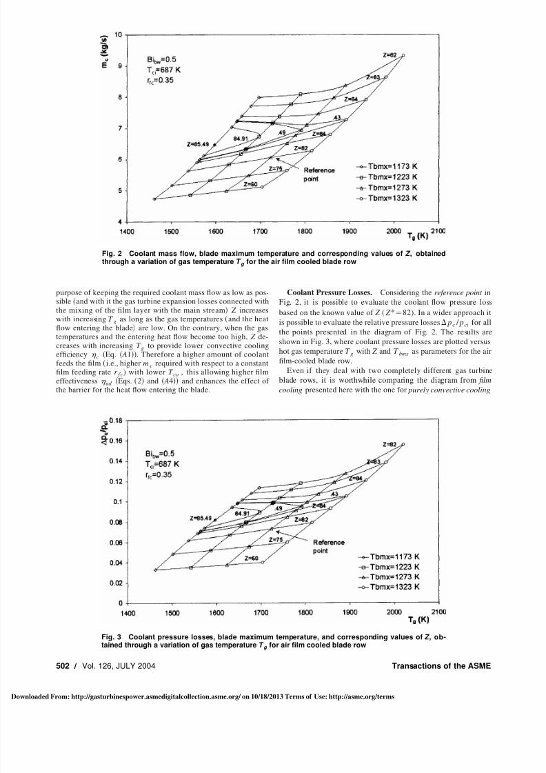
purpose of keeping the required coolant mass flow as low as pos-sible and with it the gas turbine expansion losses connected withthe mixing of the film layer with the main stream Z increaseswith increasing T g as long as the gas temperatures and the heatflow entering the blade are low. On the contrary, when the gastemperatures and the entering heat flow become too high, Z de-creases with increasing T g to provide lower convective coolingefficiency c Eq. A1 . Therefore a higher amount of coolantfeeds the film i.e., higher mc required with respect to a constantfilm feeding rate r f c) with lower T co , this allowing higher filmeffectiveness ad Eqs. 2 and A4 and enhances the effect of the barrier for the heat flow entering the blade.
Coolant Pressure Losses. Considering the reference point in
Fig. 2, it is possible to evaluate the coolant flow pressure loss
based on the known value of Z ( Z *ϭ82). In a wider approach it
is possible to evaluate the relative pressure losses ⌬ p c / pci for all
the points presented in the diagram of Fig. 2. The results are
shown in Fig. 3, where coolant pressure losses are plotted versus
hot gas temperature T g with Z and T bmx as parameters for the air
film-cooled blade row.
Even if they deal with two completely different gas turbine
blade rows, it is worthwhile comparing the diagram from film
cooling presented here with the one for purely convective cooling
Fig. 2 Coolant mass flow, blade maximum temperature and corresponding values of Z , obtainedthrough a variation of gas temperature T g for the air film cooled blade row
Fig. 3 Coolant pressure losses, blade maximum temperature, and corresponding values of Z , ob-tained through a variation of gas temperature T g for air film cooled blade row
502 Õ Vol. 126, JULY 2004 Transactions of the ASME
wnloaded From: http://gasturbinespower.asmedigitalcollection.asme.org/ on 10/18/2013 Terms of Use: http://asme.org/terms

7/27/2019 498_1
http://slidepdf.com/reader/full/4981 6/9
presented by the authors in their previous work i.e., Fig. 6 in 10 . It becomes evident that the relative pressure loss in convec-tive cooling rises more rapidly with T g than in film cooling. Thisis determined by the increasing value of Z , which is the only wayto deal with the effects of the rising gas temperature in a convec-tively cooled blade: In fact, in this case Z can reach very highvalues. In accordance with Eq. 1 , higher values of Z correspondto more cooling channels with lower hydraulic diameter d , whichin turn means a higher pressure loss for the coolant flow. A dif-
ferent situation is presented in the diagram in Fig. 3, where theadopted film cooling method allows the Z parameter values to bekept low and so to keep pressure losses low.
Film Cooling With Alternative Coolants
A sample of the analysis for film cooling performed with alter-native coolants is presented here.
Fig. 4 Coolant mass flow required by the blade row when film cooled with air „dotted lines… orcarbon dioxide „solid line…, for varying gas temperature T g , maximum blade temperature T bmx andtechnology level parameter Z
Fig. 5 Relative coolant pressure drop for the blade row when film cooled with air „dotted lines… orcarbon dioxide „solid line…, for varying gas temperature T g , maximum blade temperature T bmx andtechnology level parameter Z
Journal of Engineering for Gas Turbines and Power JULY 2004, Vol. 126 Õ 503
wnloaded From: http://gasturbinespower.asmedigitalcollection.asme.org/ on 10/18/2013 Terms of Use: http://asme.org/terms

7/27/2019 498_1
http://slidepdf.com/reader/full/4981 7/9
The parameter Z having been determined, the internal geometryof the blade is sufficiently known to evaluate the cooling of thesame blade row when alternative coolants are adopted in place of dry air see Fig. 1 . The calculations were carried out using ex-actly the same input data as for Figs. 2 and 3, except for thedifferent coolant composition which was carbon dioxide. Forcomparison, the results for air cooling shown in Figs. 2 and 3 arereproduced in dotted lines in Figs. 4 and 5, respectively. The dia-gram in Fig. 4 shows the coolant mass flow required versus hotgas temperature and Fig. 5 shows coolant relative pressure drops.It can be seen that carbon dioxide cooling substantially reduces
the coolant mass flow requirement with respect to that of air.The pressure losses inside the blade are also greatly reduced.Considering that the cooling system geometry, and with it also thecooling channel diameter, are equal for the same values of Z , thereduction of the pressure loss for the carbon dioxide cooling de-pends on i the different thermophysical properties of the coolantand ii the different rate of the coolant mass flow required i.e., adifferent coolant velocity through the constant cooling channelgeometry . Since the pressure losses depend also on the square of the velocity, their reduction becomes more evident for high valuesof the hot gas temperature, due to the increasing coolant velocity.
It is possible to conclude that the carbon dioxide cooling per-forms better than that with dry air, and also that the improvementis much more evident for high values of the hot gas temperature.In that range, in fact, the alternative coolant allows for a sensitivereduction of both the coolant pressure loss and the coolant massflow rate requirement this last being also connected with the gasturbine expansion losses caused by the mixing of the film layerwith the hot gas stream .
Conclusions
In order to perform reliable innovative gas-turbine cycle calcu-lations, a new computational tool for the analysis of film cooledblades and vanes is proposed. It consists of an analytical proce-dure for the investigation of the film cooling starting with theknowledge of the blade row geometry required to run the simula-tion. The effect of the internal blade geometry i.e., cooling chan-nels geometry on the cooling performance is considered throughthe cooling system technology level parameter Z . The procedure is
able to automatically set a proper value for Z by means of asemi-empirical assessment module. As the assessment module re-lies on semi-empirical data, the Z setting is determined with re-spect to existing technology.
Once Z is determined, the internal blade configuration is deter-mined, which makes it possible to calculate the pressure losses of the coolant and the behavior of a given blade configuration in anenvironment consisting of a new cooling medium and/or a newhot gas composition. It is also possible to study how Z should bealtered for, e.g., by varying hot gas temperature, in order to avoidexcessive coolant mass flow or a pressure drop. This means thatvaluable information on blade design requirements for alternativefluids can be obtained.
Therefore the following main conclusions may be stated:
i. the method proposed here allows a very detailed analysis of
blade cooling influence on innovative gas turbine cycle per-formance, and it is a noteworthy step in this field;
ii. when traditional cooling fluids are investigated, the modelrepresents a very detailed method to evaluate not only themass flow rate m c , but also the coolant pressure loss;
iii. when alternative fluids are investigated and the semi-empirical data become not anymore available, the proposedanalytical model overcomes the limits of the semi-empiricalapproach, thanks to the preliminary ‘‘ Z ’’ analysis carried outwith air as coolant.
Planned future work is to extend the integration approach toinclude the analytical expansion model. This should provide a
method for the analysis of the cooled gas turbine on a cycle levelwith increased reliability for alternative coolants and workingmedia.
Appendix
The Semi-Empirical Assessment Module. The semi-empirical assessment module relies on knowledge based on exist-ing technology in order to allow the presented analytical code toset a proper value for the cooling system technology level param-eter Z . It uses conventional air cooled blade semi-empirical curves
to calculate the amount of coolant mc required to cool one gasturbine blade row and the temperature T co of the coolant as itleaves the blade and mixes with the hot gas stream. The funda-mental equations for the module can be found in Holland andThawke 20 and the procedure is based on the ‘‘standard blade’’assumption presented by Halls 21 . A standard blade has a uni-form blade temperature T bu equal to the average temperature of that in the actual blade, the same geometry as the actual blade, andthe cooling air is warmed up to the uniform blade temperaturebefore leaving the blade. The cooling efficiency c describes theratio between the temperature rise of the coolant flow in the actualblade and in the standard blade:
cϭ
T coϪT ci
T buϪT ci
. ( A1)
For film cooled blades, T co is the temperature to which thecoolant flow is warmed before emerging from the blade to feedthe film. Instead, T ci is the temperature of the coolant entering theblade row at the inlet section.
When the film cooling method is adopted, the value of thecooling efficiency is determined by the equation
cϭ
cϪ ad
BϪ ad 1Ϫ c
( A2)
where the cooling effectiveness c is defined as
cϭ
T gϪT bu
T gϪT ci
( A3)
and for the adiabatic wall film effectiveness ad Eq. 2 isadopted.
The cooling parameter B, referred to as wϩ by Holland andThawke 20 , is included in the expression
mc
mg
ϭ Bc pg
c pc
Stg
Ab
Ag
. ( A4)
The relationship between c and B is determined through theuse of semi-empirical data, a principle that was previously usedby Rosen 22 . Semi-empirical diagrams of c as a function of Bcan be found in works by Haselbacher 23 and Mukherjee 24 .The data from these two references are plotted in Fig. A1.
In the present work, the data comes from the diagram presentedby Haselbacher, and the curve adopted in the calculation is theaverage one between the lower and upper limit curves that de-scribe the film cooling Fig. A2 . Thermal analysis for the film
cooled blade is the same as that for the convective cooled blade, 10 , except that the hot gas temperature T g must be replaced bythe average film temperature T F . Another very important aspect ishow the external convective heat transfer coefficient varies in thepresence of film cooling. The lack of knowledge forces the analystto assume the same correlation as in the case of purely convectivecooling to evaluate the external heat transfer coefficient also in thepresence of film cooling, 12 . Thus Eq. A2 produces the expres-sion for the effect of film cooling, expressed in terms of adiabaticwall film effectiveness ad , on the cooling efficiency of a convec-tive plus film cooled blade c . The same Eq. A2 can be trans-posed in such a way as to give for a purely convective cooled blade:
504 Õ Vol. 126, JULY 2004 Transactions of the ASME
wnloaded From: http://gasturbinespower.asmedigitalcollection.asme.org/ on 10/18/2013 Terms of Use: http://asme.org/terms

7/27/2019 498_1
http://slidepdf.com/reader/full/4981 8/9
cF Aϭc
B 1Ϫ c
. ( A5)
By substituting the appropriate values for the film cooled bladeson the right-hand side of Eq. A5 , the apparent convective cool-ing efficiency of a film cooled blade cFA is obtained. The effi-ciency value deriving from Eq. A5 is the value to be read whenthe film cooled blade is plotted on the conventional correlationgraph such as in Figs. A1 and A2, 12 .
Apart from selecting the appropriate curve from Fig. A1, theparameters to be set in order to run a solution are the geometryparameter Ab / Ag i.e., wetted blade and adjacent surfaces to becooled over average gas cross-sectional area , the hot gas side
Stanton number Stg , the adiabatic wall film effectiveness ad ,and the uniform blade temperature T bu . The value of Ab / Ag was
set equal to five in the work presented by Jordal 25 , a value thatwas previously proposed by Bolland and Stadaas 26 . The samevalue has been adopted based on the external geometry of theblade row investigated here. The value of Stg was provided by
correlation with the main analytical code and so passed to theassessment module as shown in Fig. 1. The adiabatic wall filmeffectiveness ad is also adopted as it is evaluated by the code.
The input and output for the semi-empirical module are listed inTable 1. The main parameter that remains to be set in order tocomplete the input for one blade row is the uniform blade tem-perature T bu .
Fig. A1 c as a function of B , reproduced with data from Haselbacher „dotted lines…, and Mukherjee „solid lines…
Fig. A2 c as a function of B , reproduced with data from Haselbacher for film cooling „i.e., average curve…
Journal of Engineering for Gas Turbines and Power JULY 2004, Vol. 126 Õ 505
wnloaded From: http://gasturbinespower.asmedigitalcollection.asme.org/ on 10/18/2013 Terms of Use: http://asme.org/terms

7/27/2019 498_1
http://slidepdf.com/reader/full/4981 9/9
Nomenclature
Ab ϭ wetted surface of the blade row bladesϩshrouds Ag ϭ actual gas cross-sectional area
a t ϭ ratio between bladeϩshroud surface and blade sur-face
B ϭ dimensionless coolant parameterBi ϭ Biot number
c ϭ chordc p ϭ specific heat at constant pressure
d ϭ cooling channel hydraulic diameterdll ϭ dynamic link library
E h ϭ parameter that considers increased surface of coolingchannels due to turbulators
h ϭ convective heat transfer coefficientK comb ϭ combustion pattern factor
M ϭ film blowing ratem ϭ mass flow rate
nch ϭ number of the cooling channels inside the bladen p ϭ number of cooling channel passages p ϭ pressure
Pr ϭ Prandtl numberRe ϭ Reynolds numberr f c ϭ fraction of the coolant flow used for film coolingSt ϭ Stanton numberT ϭ temperature
t b ϭ average blade thickness, blade cross-sectional area / c
TBC ϭ thermal barrier coatingU ϭ velocity
W ϭ molar weightw ϭ injection slot widthx ϭ distance in downstream chordwise direction from the
film injection location Z ϭ blade cooling system technology level parameter␣ ϭ film injection angle␣ h ϭ ratio, empty blade cross-sectional area / c 2
⌬ ϭ arithmetic differencec ϭ cooling effectiveness c ϭ cooling efficiency
ad ϭ adiabatic wall film cooling effectiveness cFA ϭ apparent convective cooling efficiency of the film
cooled blade
ϭ
dynamic viscosity ϭ kinematics viscosity ϭ density ϭ solidity
⌿g ϭ parameter that accounts for the reduction of the gascross-sectional area due to the blade thickness,
1Ϫ *t b / c⌿ i ϭ parameter that considers influence of heat transfer
between adjacent cooling channels
Subscripts
b ϭ bladebw ϭ blade wall
c ϭ coolant, cooling, coolant sidecomb ϭ combustion chamber
F ϭ film layer
g ϭ gas, gas sidei ϭ inlet
mx ϭ maximumo ϭ outletu ϭ uniformw ϭ related to the film injection slot
Superscripts
* ϭ reference pointMAX
ϭ maximum
References
1 Rao, A. D., 1989, ‘‘Process for Producing Power,’’ U.S. Patent No. 4,829,763. 2 Traverso, A., and Massardo,A. F., 2002, ‘‘Thermoeconomic Analysis of Mixed
Gas-Steam Cycles,’’ Appl. Therm. Eng., 22, pp. 1–21, Elsevier, New York. 3 Harvey, S. P., and Richter, H. J., 1994, ‘‘Gas Turbine Cycles With Solid Oxide
Fuel Cells,’’ ASME J. Energy Resour. Technol., 116.
4 Massardo, A. F., and Lubelli, F., 2000, ‘‘Internal Reforming Solid Oxide Fuel
Cell—Gas Turbine Combined Cycles—Part I: Cell Model and Cycle Thermo-
dynamic Analysis,’’ ASME J. Eng. Gas Turbines Power, 122, pp. 27–35. 5 Mathieu, P., and Nihart, R., 1998, ‘‘Zero Emission Matiant Cycle,’’ ASME,
Paper No. 98-GT-383. 6 Stambler, I., 2000, ‘‘Steam-Cooled H-Technology Machines Set for Commer-
cial Operation in 2002,’’ Gas Turb. World, Jan–Feb.
7 Layne, A. W., and Hoffman, P. A., 1999, ‘‘Gas Turbine Systems for the 21st
Century,’’ ASME, Paper No. 99-GT-367. 8 Layne, A. W., 2000, ‘‘Developing the Next Generation Gas Turbine
Systems—A National Partnership,’’ ASME Paper No. 2000-GT-176. 9 Massardo, A. F., and Scialo, M., 2000, ‘‘Thermoeconomic Analysis of Gas
Turbine Based Cycles,’’ ASME J. Eng. Gas Turbines Power, 122.
10 Jordal, K., Torbidoni, L., and Massardo, A. F., 2001, ‘‘Convective Blade Cool-
ing Modeling for the Analysis of Innovative Gas Turbine Cycles,’’ ASMEPaper No. 2001-GT-0390.
11 Torbidoni, L., 2000, ‘‘Espansione Refrigerata nel Turbogas al Variare delleTecniche e dei Fluidi di Raffreddamento,’’ Tesi di Laurea, DIMSET, Italy.
12 Holland, M. J., 1992, ‘‘Cranfield Lecture Notes—Rotor Blade Cooling in HP
Turbines,’’ Technical Report, Department of Turbine Technology, Ref.
GN30884, Rolls Royce plc. 13 Goldstein, R. J., and Haji-Sheikh, A., 1967, ‘‘Prediction of Film Cooling Ef-
fectiveness,’’ Proc. 1967, Semi-International Symposium (Tokyo), Japan Soci-ety of Mechanical Engineers, Tokyo, pp. 213–218.
14 Louis, J. F., 1977, ‘‘Systematic Studies of Heat Transfer and Film Cooling
Effectiveness,’’ AGARD CP 229. 15 Young, J. B., and Wilcock, R. C., 2001, ‘‘Modeling the Air-Cooled Gas
Turbine—Part II: Coolant Flows and Losses,’’ ASME Paper No. 2001-GT-
0392. 16 Consonni, S., 1990, ‘‘Performance Prediction of Gas/Steam Cycles for Power
Production,’’ MAE Dept., Ph.D. thesis No. 1893-T, Princeton University, Prin-
ceton, NJ. 17 Anon, 1998, ‘‘IPSEpro User Documentation,’’ Simtech Simulation Technol-
ogy, Graz, Austria. 18 Jordal, K., and Torbidoni, L., 2000, ‘‘Linking of a Fortran Code to IPSEpro,’’
DIMSET, Internal report TN 4-2000, Italy.
19 Perry, R. H., and Green, D., 1984, Perry’s Chemical Engineers’ Handbook , 6th
Ed., McGraw-Hill, New York. 20 Holland, M. J., and Thawke, T. F., 1980, ‘‘Rotor Blade Cooling in High Pres-
sure Turbines,’’ Int. J. of Aircraft Eng., 17 6 . 21 Halls, G. A., 1969, ‘‘Air Cooling of Turbine Blades and Vanes,’’ AGAR-
Dograph No. 120.
22 Rosen, P. M., 1993, ‘‘Evaporative Gas Turbines—A Thermodynamic Evalua-
tion of Their Potential,’’ Report No. ISRN/LUTMDN/TMVK-7010-SE, Lund
University. 23 Haselbacher, H., 1989, ‘‘Gas Turbines,’’ Standard Handbook of Power Plant
Engineering, Thomas C. Elliot, ed., McGraw-Hill, New York.
24 Mukherjee, D. K., 1977, Zu r Schaufelku hlung der Gasturbine, Brown Boweri
Mitteilungen.
25 Jordal, K., 1999, ‘‘Gas Turbine Cooling Modeling—Thermodynamic Analysis
and Cycle Simulations,’’ Report No. ISRN LUTMDN/TMVK-7034-SE, Lund
University.
26 Bolland, O., and Stadaas, J. F., 1995, ‘‘Comparative Evaluation of CombinedCycles and Gas Turbine Systems With Water Injection, Steam Injection and
Recuperation,’’ ASME J. Eng. Gas Turbines Power, 117.
506 Õ Vol. 126, JULY 2004 Transactions of the ASME