生存圏研究所学際萌芽研究センター第96回定例オープ … · thorough research on...
TRANSCRIPT
1
生存圏研究所学際萌芽研究センター第96回定例オープンセミナー資料 2009/07/15
Title : Computer Modelling of Timber Structures Speaker : Dr Zhongwei Guan (Senior Lecturer in Structural Engineering, Department of
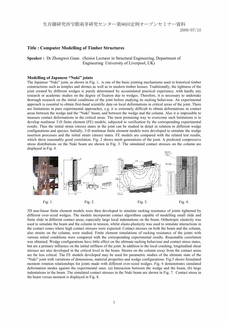
Engineering University of Liverpool, UK) Modelling of Japanese “Nuki” joints The Japanese “Nuki” joint, as shown in Fig. 1, is one of the basic jointing mechanisms used in historical timber constructions such as temples and shrines as well as in modern timber houses. Traditionally, the tightness of the joint created by different wedges is purely determined by accumulated practical experience, with hardly any research or academic studies on the degree of fixation due to wedges. Therefore, it is necessary to undertake thorough research on the initial conditions of the joint before studying its racking behaviour. An experimental approach is essential to obtain first-hand scientific data on local deformations in critical areas of the joint. There are limitations in pure experimental approaches, e.g. it is extremely difficult to obtain deformations in contact areas between the wedge and the “Nuki” beam, and between the wedge and the column. Also it is impossible to measure contact deformations in the critical areas. The most promising way to overcome such limitations is to develop nonlinear 3-D finite element (FE) models, subjected to verification by the corresponding experimental results. Thus the initial strain (stress) states in the joint can be studied in detail in relation to different wedge configurations and species. Initially, 3-D nonlinear finite element models were developed to simulate the wedge insertion processes and the initial strain (stress) states. FE models are compared with the related test results, which show reasonably good correlation. Fig. 2 shows mesh generations of the joint. A predicted compressive stress distributions on the Nuki beam are shown in Fig. 3. The simulated contact stresses on the column are displayed in Fig. 4.
Fig. 1. Fig. 2. Fig. 3. Fig. 4.
3D non-linear finite element models were then developed to simulate racking resistance of joints tightened by different over-sized wedges. The models incorporate contact algorithms capable of modelling small slide and finite slide in different contact areas, especially large local indentations on the beam. Orthotropic elasticity was used to simulate the beam and the column in tension, whilst elasto-plasticity was used to simulate interactions in the contact zones where high contact stresses were expected. Contact stresses on both the beam and the column, also strains on the column, were studied. Finite element simulations of racking resistance of the joints with various initial conditions were compared with the corresponding experimental results. Reasonable correlation was obtained. Wedge configurations have little effect on the ultimate racking behaviour and contact stress states, but are a primary influence on the initial stiffness of the joint. In addition to the local crushing, longitudinal shear stresses are also developed in the critical level in the beam. Strains on the column away from the contact areas are far less critical. The FE models developed may be used for parametric studies of the ultimate state of the “Nuki” joint with variations of dimensions, material properties and wedge configurations. Fig.5 shows Simulated moment–rotation relationships for joints made with different over-sized wedges. Fig. 6 demonstrates simulated deformation modes against the experimental ones: (a) Interaction between the wedge and the beam, (b) large indentations in the beam. The simulated contact stresses in the Nuki beam are shown in Fig. 7. Contact stress in the beam versus moment is displayed in Fig. 8.

2
Fig. 5. Fig. 6. Fig. 7. Fig. 8. Guan Z. W., Kitamori, A. and Komatsu, K., "Experimental study and FE modelling of Japanese “Nuki” joints, part one: inital stress states subjected to different wedge configurations", Engineering Structures, 2008, 30. pp 2032–2040. Guan Z. W., Kitamori, A. and Komatsu, K., "Experimental study and FE modelling of Japanese “Nuki” joints, part two: racking resistance subjected to different wedge configurations", Engineering Structures, 2008, 30. pp 2041–2049. Modelling of OSB webbed wood I-beams with openings OSB webbed timber I-beams have been widely used in construction industry in Europe and North America, due to a number of advantages, such as engineered features, material savings, low handling costs and its environmental friendly nature. Openings in webs, usually square or circular shaped, are often needed to allow services to pass through. Openings made through the webs will affect the structural performance of beams to different extents, depending upon the opening location, size and beam depth. Stress distributions around an opening are complicated, varying between tension and compression, depending on loading conditions and deformation modes. OSB and timber can be either treated as anisotropic or orthotropic materials, dependent upon whether the structural behaviour through the panel thickness plays a more important role in comparison with in-plane behaviour. Both materials behave differently in tension and compression. Experiments show that OSB in tension behaves almost linearly up to failure, whilst in compression it exhibits obvious plasticity. Therefore, it is necessary to develop appropriate constitutive models that can deal with the constituent materials under different stress states automatically, by implementing them into computer models. Here timber composite I-beams with openings were modelled, using a user defined subroutine, which was implemented into the FE package ABAQUS. The Tsai_Hill criterion was applied to judge failure of OSB in tension. The user-defined subroutine is capable of distinguishing and tracing tension and compression zones in the flange and the web, and modeling those zones with different constitutive models accordingly. Both OSB and timber in tension were modelled as linear orthotropic elastic materials, and in compression as orthotropic elasto-plastic materials Good correlation has been obtained between the experimental results and the FE simulations. Crack initiation and growth were also simulated by element removal techniques controlled by the user-defined subroutine. In addition, interactions between two openings were modelled, which produced the corresponding critical distances between two circular openings, two square openings, and a circular opening and a square opening. Fig. 9 shows comparison of experimentally failed modes and numerically simulated failed modes (ratio of the opening size to the web depth is 0.75): (a) a beam with circular openings. (b) a beam with square openings. Fig. 10 displays predicted principal tensile stress in beam webs at ultimate load: (a) openings 500 mm apart, (b) openings 250 mm apart. Fig. 11 shows the predicted initial cracking load versus distance between openings (ratio of the opening size to the web depth is 0.5).
Fig. 9. Fig. 10. Fig. 11. Guan, Z. W. and Zhu, E. C., “Finite element modelling of anisotropic elasto-plastic timber composite beams with openings”, Engineering Structures, 2009, 31, pp394-403.

3
Modelling of prestressed glulam beams using GRP tendons Improvement of the load carrying capacity of glulam beams by the addition of reinforcement is now common practice. Recently it has been demonstrated that pre-stressing of beams using pultruded glass fibre reinforced plastic (GRP) tendons provides an available alternative due to the compatibility of the two materials and the low losses of pre-stress. This paper describes a finite element based model which was validated against test results and then used to investigate bond stress between a pre-stressed GRP tendon and the adjacent timber. Parametric studies were also undertaken to evaluate the effects of tendon thickness, beam span and the pre-tension force on the structural behaviour of beams. A tendon thickness of 4 mm and a pre-tensioning force of 60% of the ultimate tensile strength of the GRP were seen as limits for the particular beam size studied in order to maximise the structural performance of the beam. Fig. 12 shows an end view of the pre-stressed glulam beam. Fig. 13 displays longitudinal contact shear stress distributions in the end section: (a) at the contact surface of the bottom laminate and (b) at the contact surface of the upper glulam section (inverted). Pre-camber for beams pre-stressed with different tendon thicknesses is shown in Fig. 14 and pre-camber for beams of different spans in Fig.15
Fig. 12. Fig. 13. Fig. 14. Fig. 15. Guan, Z. W. and Rodd, P. D., “Study of glulam beams prestressed with pultruded GRP”, Computers & Structures, 2005, 83, pp 2476-2487.