bande2
DESCRIPTION
hvacTRANSCRIPT
This article appeared in a journal published by Elsevier. The attachedcopy is furnished to the author for internal non-commercial researchand education use, including for instruction at the authors institution
and sharing with colleagues.
Other uses, including reproduction and distribution, or selling orlicensing copies, or posting to personal, institutional or third party
websites are prohibited.
In most cases authors are permitted to post their version of thearticle (e.g. in Word or Tex form) to their personal website orinstitutional repository. Authors requiring further information
regarding Elsevier’s archiving and manuscript policies areencouraged to visit:
http://www.elsevier.com/copyright
Author's personal copy
Elevator shaft pressurization for smoke control in tall buildings: The Seattleapproach
Richard S. Miller*
Department of Mechanical Engineering, Clemson University, Clemson, SC 29634-0921, USA
a r t i c l e i n f o
Article history:Received 18 February 2011Received in revised form27 April 2011Accepted 8 May 2011
Keywords:Smoke controlPressurizationElevatorHoistwaySeattleInternational building code
a b s t r a c t
CONTAM simulations of both commercial and residential tall building models are conducted in order tostudy recently adopted Seattle code requirements for elevator shaft pressurization systems. In contrast tothe International Building Code (IBC) requirements, the Seattle approach specifies across elevator doorpressure minimums and maximums on only four “fire floors” (including one above, and two below, thefire floor). This is accomplished using a minimal pressurization of the entire elevator shaft in conjunctionwith venting of the four fire floors. The present study adresses the feasibility of calibrating such a systemto meet the design objectives in tall buildings (system performance during an actual fire event is notconsidered). The two building models correspond to 37 story buildings with dual elevator and dualstairwell shafts extending the entire height of the building. Each model is calibrated to experimentaldata. Simulations are conducted for a variety of ambient temperatures and exterior building doorpositions. Coupled pressurization of the stairwells is also considered. The system requirements are foundto be achievable for both elevator only and coupled elevator and stairwell pressurization systems.However, the observed pressure differences do change with changes in the ambient temperature as wellas changes in the ground floor exterior door position. It is therefore recommended that such systemsshould be calibrated for pressure differences intermediate to the prescribed minimum and maximumvalues to compensate for changes to the system performance. Providing a relief vent to ambient on anyrecall floor may also be advisable.
� 2011 Elsevier Ltd. All rights reserved.
1. Introduction
Stairwells and elevator shafts can be dangerous conduits ofsmoke migration throughout buildings during fire situations.Smoke penetrating the shaft can spread through both the buoyancyof hot gases as well as by the stack effect which occurs when thereis a temperature difference between the air in the shaft and the airin the outside environment [1]. One method for controlling smokeflow is by using shaft pressurization. The intent of pressurizationsystems is to use outside air to pressurize a shaft such that onlypositive across door pressures are achieved on all floors. Thisrequires the specification of a suitable minimum pressure neededto prevent smoke from entering the shaft, as well as the specifi-cation of a suitablemaximumpressure difference in order to ensureproper door functioning. For example, the pertinent sections of theInternational Building Code (IBC) 2009 relevant to stairwell pres-surization systems states in part (Section 909.20.5): “the vestibule
is not required, provided that interior exit stairways are pressurizedto a minimum of þ25 Pa and a maximum of þ87 Pa in the shaftrelative to the building measured with all stairway doors closedunder maximum anticipated stack effect pressures.” Stairwellpressurization has been approved and adopted for a relatively longtime. In contrast, the use of elevator shaft pressurization has onlyrecently received approval by the IBC and relatively little researchhas been done in this area. The pertinent section of the code rele-vant to elevator shaft pressurization (Section 708.14.2) states inpart: “Elevator hoistways shall be pressurized to maintaina minimum positive pressure of þ25 Pa and a maximum positivepressure of þ62.5 Pa with respect to adjacent occupied space on allfloors. This pressure shall be measured with all elevator cars at thefloor of recall and all hoistway doors on the floor of recall open andall other doors closed.”
The author has sought to fill this gap in the literature and hasbeen studying elevator pressurization using numerical simulations[2e5]. The results of these studies have shown that elevator pres-surization is much more complex than stairwell pressurization.Stairwells are characterized by relatively well sealed doorwayswhich are in the closed position during pressurization operation. As
* Tel.: þ1 864 656 6248; fax: þ1 864 656 4435.E-mail address: [email protected].
Contents lists available at ScienceDirect
Building and Environment
journal homepage: www.elsevier .com/locate/bui ldenv
0360-1323/$ e see front matter � 2011 Elsevier Ltd. All rights reserved.doi:10.1016/j.buildenv.2011.05.007
Building and Environment 46 (2011) 2247e2254
Author's personal copy
such, stairwell pressurization is relatively straight forward andrequires only relatively modest fan flow rates to achieve estab-lished pressure difference minimums. In contrast, elevator shaftsare characterized by doors with relatively large leakages, and oftenmultiple doors per floor. In addition, the IBC 2009 recognizes thatminimum and maximum pressure differentials be achieved duringPhase 1 “with all elevator cars at the floor of recall and all hoistwaydoors on the floor of recall open and all other hoistway doorsclosed.” Therefore, substantially larger fan flow rates are required topressurize an elevator shaft; in some cases more than ten times theflow rates required to pressurize a stairwell. Pressurized elevatorair flows exit the hoistway and enter the building corridors on allfloors, with especially large flow rates at the recall floor. Such largeamounts of air flooding the building can result in complex pressureprofiles as well as strong interactions with stairwell pressurizationsystems. In particular, if the recall floor does not have an openpathway to the outside world for excess elevator shaft air flows toexit the building, then it is impossible to achieve pressure profileswithin the both the stairwells and elevator shafts that do notviolate either the pressure difference minimums and maximumsspecified by the IBC 2009 code. Such a venting is not currentlyrequired by the IBC 2009. Substantial coupling effects between theelevator and stairwell pressurization systems were also observed.The presence of an open garage level can also impede the ability toachieve proper system performance. For buildings with otherinterior doors, such as those to residences, very large pressuresmayinadvertently be created by the elevator pressurization systemacross these doors [5]. The reader is referred to the above citationsfor more details concerning the IBC approach to pressurization.
The objective of the current study is to extend the investigationof pressurization systems beyond the methodology adopted by theIBC. In particular, a new approach recently adopted by the Seattlejurisdiction is studied. The “Seattle approach” to elevator shaftpressurization is based on a modification of the IBC code languagewhich results in the allowance of a substantially different approach.The Seattle Building Code (SBC) (Section 708.14.2.1) allows fora “four-floor” approach aimed at targeting the primary fire floor,the floor directly above, and two floors immediately below the firefloor (the approach was first proposed by Dr. John Klote, co-authorof the Principles of Smoke Management [1]). The across elevatordoor pressure differences on these four floors are treated identi-cally to the IBC language and must remain within a pressure rangeof 25e62.5 Pa. However, the code allows for the following excep-tion: “The pressure differential is permitted to bemeasured relativeto outdoor atmosphere on floors other than the.” four fire floors.In practice, for floors other than the four fire floors the pressure israised via pressurization until a minimum 25 Pa to atmospherepressure drop from the hoistway is achieved. This total pressuredrop will be comprised of the sum of pressure drops across theelevator doors, any interior pressure drops, plus the pressure dropacross the outer building wall. As such, the actual across elevatordoor pressure differences will be (considerably) less than 25 Pa onthese floors. The four fire floors are then vented to develop thedesired pressure differentials across the doors by relieving theover-pressures on these floors. Both exhaust shafts and the HVACsystem have been proposed as sources of the venting. In addition,the SBC now allows the same procedure to be used for the stair-wells. The code change was adopted during the summer of 2010and the author is not aware of any publications addressing sucha design.
2. Modeling approach
The following presents results obtained by computer simula-tions of model buildings utilizing both elevator and stairwell
pressurization based on the Seattle approach. All results wereobtained via computer simulations using the CONTAM softwaredeveloped by the Indoor Air Quality and Ventilation Group at theNational Institute of Standards and Technologies. The software isa zonal model in which a building geometry is composed ofa number of zones (rooms, shafts, floors, etc.). Each zone is treatedas a lumped parameter with only hydrostatic pressure variationswithin the zone (dynamic pressure variations being five or moreorders of magnitude smaller for the present application). Only the“long time” equilibrium pressure distributions are predicted.Details of the software can be found at http://www.bfrl.nist.gov/IAQanalysis/index.html. Note too that only the ability of thesystem to meet its design minimum and maximum pressuredifferences as prescribed by the SBC are considered in this paper.Neither the wisdom of only considering the four fire floors nor theperformance of the systems under an actual fire event areconsidered.
2.1. Building models
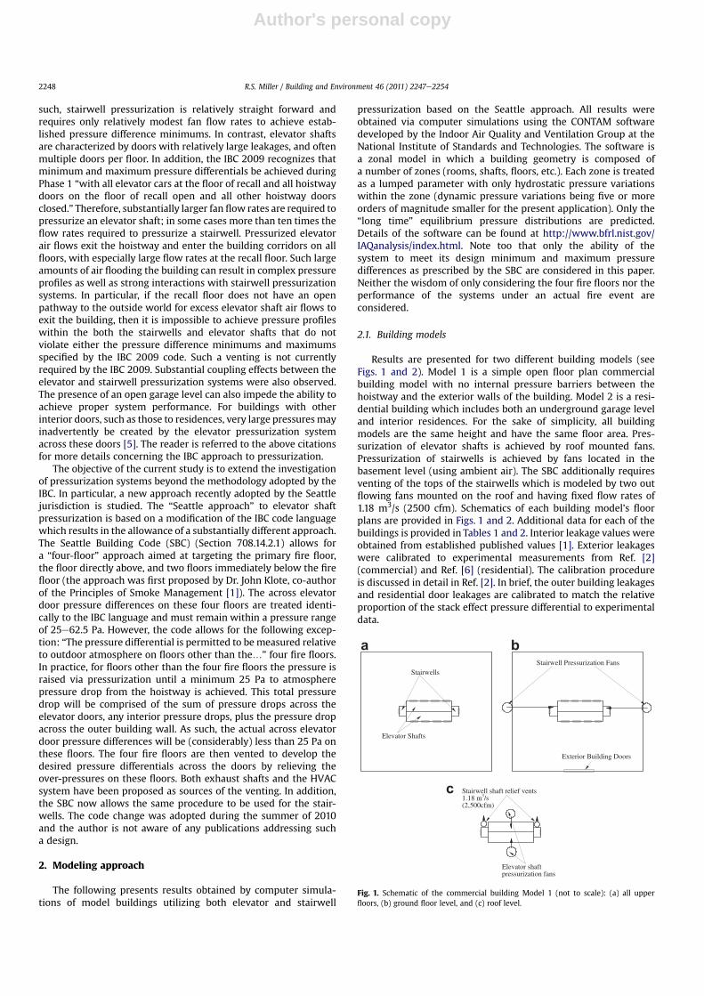
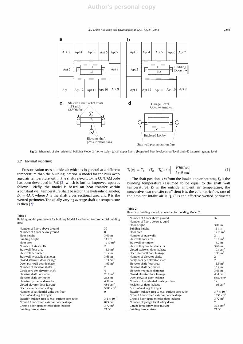
Results are presented for two different building models (seeFigs. 1 and 2). Model 1 is a simple open floor plan commercialbuilding model with no internal pressure barriers between thehoistway and the exterior walls of the building. Model 2 is a resi-dential building which includes both an underground garage leveland interior residences. For the sake of simplicity, all buildingmodels are the same height and have the same floor area. Pres-surization of elevator shafts is achieved by roof mounted fans.Pressurization of stairwells is achieved by fans located in thebasement level (using ambient air). The SBC additionally requiresventing of the tops of the stairwells which is modeled by two outflowing fans mounted on the roof and having fixed flow rates of1.18 m3/s (2500 cfm). Schematics of each building model’s floorplans are provided in Figs. 1 and 2. Additional data for each of thebuildings is provided in Tables 1 and 2. Interior leakage values wereobtained from established published values [1]. Exterior leakageswere calibrated to experimental measurements from Ref. [2](commercial) and Ref. [6] (residential). The calibration procedureis discussed in detail in Ref. [2]. In brief, the outer building leakagesand residential door leakages are calibrated to match the relativeproportion of the stack effect pressure differential to experimentaldata.
Fig. 1. Schematic of the commercial building Model 1 (not to scale): (a) all upperfloors, (b) ground floor level, and (c) roof level.
R.S. Miller / Building and Environment 46 (2011) 2247e22542248
Author's personal copy
2.2. Thermal modeling
Pressurization uses outside air which is in general at a differenttemperature than the building interior. A model for the bulk aver-aged air temperaturewithin the shaft relevant to the CONTAM codehas been developed in Ref. [2] which is further improved upon asfollows. Briefly, the model is based on heat transfer withina constant wall temperature shaft based on the hydraulic diameter,Dh ¼ 4A/P, where A is the shaft cross sectional area and P is thewetted perimeter. The axially varying average shaft air temperatureis then [7]:
TSðxÞ ¼ TB � ðTB � TOÞexp�� P0hRTOxCPQPatm
�: (1)
The shaft position is x (from the intake; top or bottom), TB is thebuilding temperature (assumed to be equal to the shaft walltemperature), TO is the outside ambient air temperature, theconvective heat transfer coefficient is h, the volumetric flow rate ofthe ambient intake air is Q, P0 is the effective wetted perimeter
a b
c d
Fig. 2. Schematic of the residential building Model 2 (not to scale): (a) all upper floors, (b) ground floor level, (c) roof level, and (d) basement garage level.
Table 1Building model parameters for building Model 1 calibrated to commercial buildingdata.
Number of floors above ground 37Number of floors below ground 0Floor height 3.00 mBuilding height 111 mFloor area 1210 m2
Number of stairwells 2Stairwell floor area 13.9 m2
Stairwell perimeter 15.2 mStairwell hydraulic diameter 3.66 mClosed stairwell door leakage 103 cm2
Open stairwell door leakage 1.95 m2
Number of elevator shafts 2Cars/doors per elevator shaft 4Elevator shaft floor area 28.8 m2
Elevator shaft perimeter 26.8 mElevator hydraulic diameter 4.30 mClosed elevator door leakage 484 cm2
Open elevator door leakage 5580 cm2
Number of residential units per floor 0External building leakages:Exterior leakage area to wall surface area ratio 3.4 � 10�4
Ground floor closed exterior door leakage 645 cm2
Ground floor open exterior door leakage 3.72 m2
Building temperature 21 �C
Table 2Base case building model parameters for building Model 2.
Number of floors above ground 37Number of floors below ground 1Floor height 3.00 mBuilding height 111 mFloor area 1210 m2
Number of stairwells 2Stairwell floor area 13.9 m2
Stairwell perimeter 15.2 mStairwell hydraulic diameter 3.66 mClosed stairwell door leakage 103 cm2
Open stairwell door leakage 1.95 m2
Number of elevator shafts 2Cars/doors per elevator shaft 2Elevator shaft floor area 13.9 m2
Elevator shaft perimeter 15.2 mElevator hydraulic diameter 3.66 mClosed elevator door leakage 484 cm2
Open elevator door leakage 5580 cm2
Number of residential units per floor 12Residential door leakage 116 cm2
External building leakages:Exterior leakage area to wall surface area ratio 3.7 � 10�4
Ground floor closed exterior door leakage 1355 cm2
Ground floor open exterior door leakage 3.72 m2
Number of garage level lobby doors 2Garage level lobby door leakage 323 cm2
Building temperature 21 �C
R.S. Miller / Building and Environment 46 (2011) 2247e2254 2249
Author's personal copy
(discussed below), and the heat capacity of the air is Cp. The bulkaveraged shaft air temperature is therefore:
TS ¼ 1H
ZH
0
TSðxÞdx; (2)
whereH is the height of the shaft. Substituting for TS(x) from Eq. (1)yields:
TS ¼ TB þðTB � TOÞCpQPatm
P0hRTOH
�exp
�� P0hRTOH
CpQPatm
�� 1
�: (3)
The primary issue remaining is properly modeling the convec-tive heat transfer coefficient. For this, the Dittus-Boelter Nusseltnumber correlation for fully developed flow in a constant walltemperature duct is employed [7]:
Nu ¼ 0:023Re0:8D Prn; (4)
where the Nusselt number is Nu ¼ hDh/k and k is the thermalconductivity of the air. In the above the pipe flow Reynolds numberis: ReD ¼ UavgDh/nwhere Uavg ¼ Q/A and n is the kinematic viscosityof the air. Also, the Prandtl number is Pr ¼ n/a, where a is thethermal diffusivity of the air. The exponent, n, takes the valuesn ¼ 0.3 for cooling and n ¼ 0.4 for heating. All properties are takenat the average temperature: (TB þ TO)/2. Implications of the fullydeveloped flow assumption are discussed in Ref. [2] and in theAppendix below.
The above thermal model is most applicable to the emptyelevator hoistways which are effectively simply large ducts uponwhich the above model is based. In contrast, the stairwells haveinterior features (the stairs) which provide a significantly largersurface area for heat transfer. For this reason the effective wettedperimeter has been defined above. For elevator shafts P0 ¼ P. Forstairwells, we model P0 ¼ bP, where b is a geometry correctionfactor. Absent any experimental data the geometry correction istaken to be b ¼ 2 for stairwells hereinafter. However, CONTAM isnot sensitive to small changes in the shaft air temperatures.
The approach described above predicts the average shaft airtemperature assuming no leakages throughout the shaft. In realityair exits the shafts at each floor through either stairwell or elevatordoors. These effects can be taken into account in the thermalmodeling. A derivation of such a thermal model is presented in theAppendix. However, the detailed thermal model is exceedinglydifficult to use in conjunctionwith CONTAM. It requires the floor byfloor flow leakages to be provided from CONTAM, and the processwould have to be iterated as changes to the predicted shaft airtemperature change the flow leakages. Nevertheless, two caseswere treated in this manner in order to justify the simpler thermalmodel. The results of the Appendix show that the above simpleapproach is in good agreement with the more detailed model;within z �2 �C for the average shaft air temperature for anambient air temperature of �12 �C. CONTAM is insensitive to suchsmall changes in temperature. Therefore, the simpler form pre-sented above is used in what follows.
3. Results
Elevator pressurization of the building models is achieved asfollows. All elevator cars are located on the ground floor with alldoors in the open position. The exterior building door is set to openand the ambient air temperature is 12 �C unless otherwise stated. Afire alarm on the 19th floor is simulated. Two identical roofmounted fans blow air into each of the elevator shafts. The fan flowrate is adjusted until a minimum pressure difference of 25 Pa is
achieved between the elevator shaft and the ambient for floorsother than floors 17e20. Since additional pressure drops remainbetween the elevator doors and the ambient, the across elevatordoor pressure differences are necessarily smaller than 25 Pa.
Four separate, but identical, fans are then placed on floors 17e20which draw air directly out of the corridor and to the ambient. Thepurpose of these fans is to drop the pressure on these floors untilthe across elevator door pressures are within the range25 / 62.5 Pa. For the purposes of this study, these fan speeds areadjusted until the maximum pressure difference of 62.5 Pa is ach-ieved across any of the elevator doors on these four floors. Smallervalues within this range could have been chosen; however, it is ofinterest to determine how changes to the building geometry,outside air temperature, etc. could result in violation of prescribedpressure differences. The choice of the maximum pressure is dis-cussed further below.
For cases which include stairwell pressurization the sameprocedure is used for the stairwells (in conjunction with the roofmounted venting fans described above). The minimum pressure onany of the non-fire floors is set to 25 Pa with respect to outsideambient. The pressures on the four fire floors cannot be set inde-pendently of the elevator doors. Any attempt to change the ventflow rate to control the across stairwell door pressure differenceswould cause a simultaneous change to the across elevator doorpressures. Therefore, for the purposes of this study themaximum ofeither the across elevator or stairwell door pressure is set equal to62.5 Pa. This could be for either the stairwell or the elevator doors,depending upon the building conditions. Again, there is someambiguity in how to best set the pressures. However, one purposeof this study is to determine how much the system behaviorchanges with changes in building conditions, and if violations ofeither the minimum or maximum pressure differences couldpotentially occur. Suggestions for proper calibration of the systemare provided in the Conclusions.
Finally, once all fan flow rates are determined they are input intothe thermalmodel to obtain new shaft air temperatures. Changes tothe shaft air temperatures result in changes to the pressures.Therefore, the entire process is iterated until a final solution isconverged. Final fan flow rates and average shaft air temperaturesare provided in Table 3 for all simulations conducted for this study.
3.1. Elevator pressurization only
As a first step in the analysis simulations for elevator-onlypressurization are conducted for both the commercial and theresidential building models. Cases 1 and 2 (see Table 3) correspondto the above description: systems calibrated for the commercialand residential building models with the exterior building doors inthe open position and with the exterior doors remaining in thisopen position. Across door pressure differences as a function of the
Table 3Simulation parameters: Case name, building model, ambient air temperature, cali-brated elevator, stairwell, and fire floor vent fan flow rates, and the average elevatorand stairwell air temperatures. All cases are calibrated with the exterior buildingdoor in the open position, except for Case 5 which is calibrated with the exteriordoor closed. Case 6 corresponds to calibration on a cold day (Case 4) but with thesystem operating on a hot day.
Cases Building TO [�C] E. fan [m3/s] S. fan [m3/s] V. fan [m3/s] TE [�C] TS [�C]
1 Model 1 �12 18.6 N/A 3.24 �8 212 Model 2 �12 11.9 N/A 1.59 �8 213 Model 1 �12 17.0 2.45 2.64 �8 �24 Model 2 �12 10.9 2.50 1.49 �8 �25 Model 2 �12 7.67 1.84 1.79 �8 �26 Model 2 32 10.9 2.50 1.49 31 28
R.S. Miller / Building and Environment 46 (2011) 2247e22542250
Author's personal copy
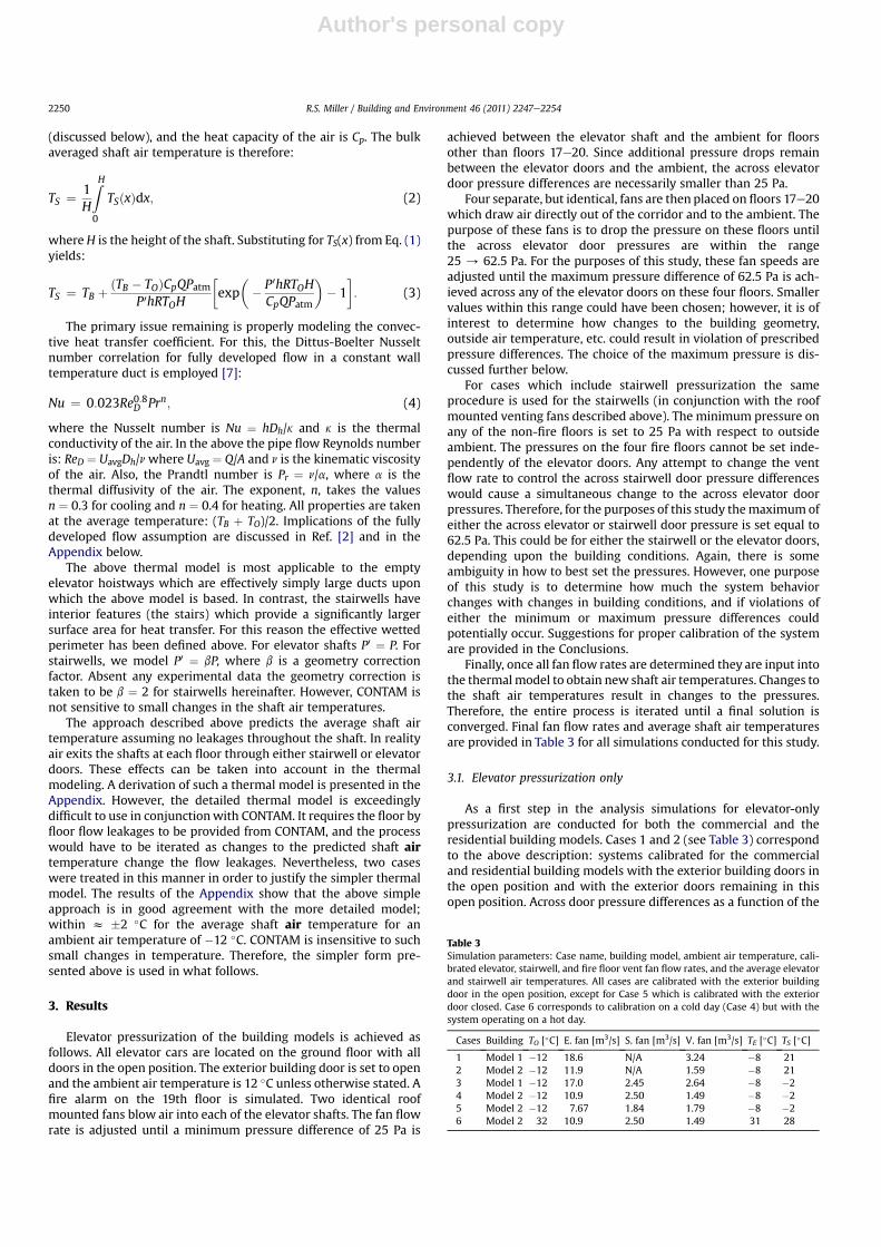
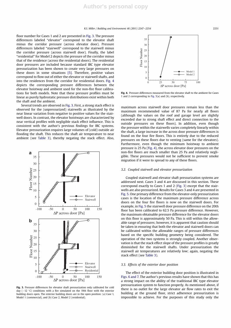
floor number for Cases 1 and 2 are presented in Fig. 3. The pressuredifferences labeled “elevator” correspond to the elevator shaftminus the corridor pressure (across elevator door). Pressuredifferences labeled “stairwell” correspond to the stairwell minusthe corridor pressure (across stairwell door). Finally, the label“residential” for Model 2 depicts the pressure of the corridor minusthat of the residence (across the residential doors). The residentialdoor pressures are included because standard IBC type elevatorpressurization has been shown to create very large pressures onthese doors in some situations [5]. Therefore, positive valuescorrespond to flow out of either the elevator or stairwell shafts, andinto the residences from the corridor for residential doors. Fig. 4depicts the corresponding pressure differences between theelevator hoistway and ambient used for the non-fire floor calibra-tions for both models. Note that these pressure profiles must belinear as purely hydrostatic pressure distributions exist within boththe shaft and the ambient.
Several trends are observed in Fig. 3. First, a strong stack effect isobserved for the (unpressurized) stairwells as illustrated by thenear linear variation from negative to positive values for the stair-well doors. In contrast, the elevator hoistways are characterized bynear vertical profiles with negligible stack effect influence. This isconsistent with the author’s previous findings for IBC systems.Elevator pressurization requires large volumes of (cold) outside airflooding the shaft. This reduces the shaft air temperature to nearambient (see Table 3), thereby negating the stack effect. Also,
maximum across stairwell door pressures remain less than themaximum recommended value of 87 Pa for nearly all floors(although the values on the roof and garage level are slightlyexceeded due to strong shaft effect and direct connection to theoutside pressures on these floors). In addition, even thoughthe pressure within the stairwells varies completely linearly withinthe shaft, a large increase in the across door pressure differences isfound on the four fire floors. This is entirely due to the reducedpressures on these floors due to venting (same for the elevators).Furthermore, even though the minimum hoistway to ambientpressure is 25 Pa (Fig. 4), the across elevator door pressures on thenon-fire floors are much smaller than 25 Pa and relatively negli-gible. These pressures would not be sufficient to prevent smokemigration if it were to spread to any of these floors.
3.2. Coupled stairwell and elevator pressurization
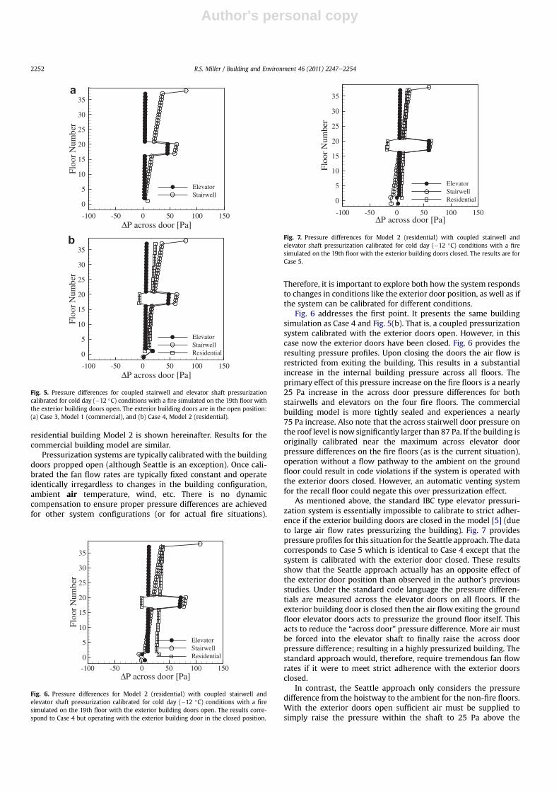
Coupled stairwell and elevator shaft pressurization systems areaddressed next. Cases 3 and 4 are discussed in this section. Thesecorrespond exactly to Cases 1 and 2 (Fig. 3) except that the stair-wells are also pressurized. Results for Cases 3 and 4 are presented inFig. 5. One primary difference from the elevator-only pressurizationcases is the location of the maximum pressure difference acrossdoors on the four fire floors is now on the stairwell doors. Forexample, in Fig. 5 the stairwell door pressure difference on the 20thfloor has been calibrated to 62.5 Pa pressure difference. However,the maximum obtainable pressure difference for the elevator doorson this floor is approximately 50 Pa. This is still within the allow-able range of pressures; however, it is apparent that caution shouldbe taken in ensuring that both the elevator and stairwell doors canbe calibrated within the allowable ranges of pressure differencesbased on the specific building geometry being considered. Theoperation of the two systems is strongly coupled. Another obser-vation is that the stack effect slope of the pressure profiles is greatlydiminished for the stairwell shafts. Under pressurization thestairwell air temperatures are relatively low; again, negating thestack effect (see Table 3).
3.3. Effects of the exterior door position
The effect of the exterior building door position is illustrated inFigs. 6 and 7. The author’s previous results have shown that this hasa strong impact on the ability of the traditional IBC type elevatorpressurization system to function properly. As mentioned above, ifthere is no outlet for the large elevator air flow rates to exit thebuilding at the ground floor, strict adherence pressurization isimpossible to achieve. For the purposes of this study only the
ΔP across door [Pa]
Flo
orN
umbe
r
-100 -50 0 50 100 150
0
5
10
15
20
25
30
35
ElevatorStairwell
ΔP across door [Pa]
Flo
orN
umbe
r
-100 -50 0 50 100 150
0
5
10
15
20
25
30
35
ElevatorStairwellResidential
a
b
Fig. 3. Pressure differences for elevator shaft pressurization only calibrated for coldday (�12 �C) conditions with a fire simulated on the 19th floor with the exteriorbuilding doors open. The exterior building doors are in the open position: (a) Case 1,Model 1 (commercial), and (b) Case 2, Model 2 (residential).
ΔP across door [Pa]
Flo
orN
umbe
r
0 25 50 75 100
0
5
10
15
20
25
30
35
Model 1Model 2
Fig. 4. Pressure differences measured from the elevator shaft to the ambient for Cases1 and 2 corresponding to Fig. 5(a) and (b), respectively.
R.S. Miller / Building and Environment 46 (2011) 2247e2254 2251
Author's personal copy
residential building Model 2 is shown hereinafter. Results for thecommercial building model are similar.
Pressurization systems are typically calibrated with the buildingdoors propped open (although Seattle is an exception). Once cali-brated the fan flow rates are typically fixed constant and operateidentically irregardless to changes in the building configuration,ambient air temperature, wind, etc. There is no dynamiccompensation to ensure proper pressure differences are achievedfor other system configurations (or for actual fire situations).
Therefore, it is important to explore both how the system respondsto changes in conditions like the exterior door position, as well as ifthe system can be calibrated for different conditions.
Fig. 6 addresses the first point. It presents the same buildingsimulation as Case 4 and Fig. 5(b). That is, a coupled pressurizationsystem calibrated with the exterior doors open. However, in thiscase now the exterior doors have been closed. Fig. 6 provides theresulting pressure profiles. Upon closing the doors the air flow isrestricted from exiting the building. This results in a substantialincrease in the internal building pressure across all floors. Theprimary effect of this pressure increase on the fire floors is a nearly25 Pa increase in the across door pressure differences for bothstairwells and elevators on the four fire floors. The commercialbuilding model is more tightly sealed and experiences a nearly75 Pa increase. Also note that the across stairwell door pressure onthe roof level is now significantly larger than 87 Pa. If the building isoriginally calibrated near the maximum across elevator doorpressure differences on the fire floors (as is the current situation),operation without a flow pathway to the ambient on the groundfloor could result in code violations if the system is operated withthe exterior doors closed. However, an automatic venting systemfor the recall floor could negate this over pressurization effect.
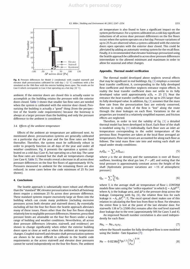
As mentioned above, the standard IBC type elevator pressuri-zation system is essentially impossible to calibrate to strict adher-ence if the exterior building doors are closed in the model [5] (dueto large air flow rates pressurizing the building). Fig. 7 providespressure profiles for this situation for the Seattle approach. The datacorresponds to Case 5 which is identical to Case 4 except that thesystem is calibrated with the exterior door closed. These resultsshow that the Seattle approach actually has an opposite effect ofthe exterior door position than observed in the author’s previousstudies. Under the standard code language the pressure differen-tials are measured across the elevator doors on all floors. If theexterior building door is closed then the air flow exiting the groundfloor elevator doors acts to pressurize the ground floor itself. Thisacts to reduce the “across door” pressure difference. More air mustbe forced into the elevator shaft to finally raise the across doorpressure difference; resulting in a highly pressurized building. Thestandard approach would, therefore, require tremendous fan flowrates if it were to meet strict adherence with the exterior doorsclosed.
In contrast, the Seattle approach only considers the pressuredifference from the hoistway to the ambient for the non-fire floors.With the exterior doors open sufficient air must be supplied tosimply raise the pressure within the shaft to 25 Pa above the
ΔP across door [Pa]
Flo
orN
umbe
r
-100 -50 0 50 100 150
0
5
10
15
20
25
30
35
ElevatorStairwellResidential
Fig. 6. Pressure differences for Model 2 (residential) with coupled stairwell andelevator shaft pressurization calibrated for cold day (�12 �C) conditions with a firesimulated on the 19th floor with the exterior building doors open. The results corre-spond to Case 4 but operating with the exterior building door in the closed position.
ΔP across door [Pa]
Flo
orN
umbe
r
-100 -50 0 50 100 150
0
5
10
15
20
25
30
35
ElevatorStairwellResidential
Fig. 7. Pressure differences for Model 2 (residential) with coupled stairwell andelevator shaft pressurization calibrated for cold day (�12 �C) conditions with a firesimulated on the 19th floor with the exterior building doors closed. The results are forCase 5.
ΔP across door [Pa]
Flo
orN
umbe
r
-100 -50 0 50 100 150
0
5
10
15
20
25
30
35
ElevatorStairwell
ΔP across door [Pa]
Flo
orN
umbe
r
-100 -50 0 50 100 150
0
5
10
15
20
25
30
35
ElevatorStairwellResidential
a
b
Fig. 5. Pressure differences for coupled stairwell and elevator shaft pressurizationcalibrated for cold day (�12 �C) conditions with a fire simulated on the 19th floor withthe exterior building doors open. The exterior building doors are in the open position:(a) Case 3, Model 1 (commercial), and (b) Case 4, Model 2 (residential).
R.S. Miller / Building and Environment 46 (2011) 2247e22542252
Author's personal copy
ambient. If the exterior doors are closed this is actually easier toaccomplish as the building retains the pressure with the exteriordoors closed. Table 3 shows that smaller fan flow rates are neededwhen the system is calibrated with the exterior door closed. Pres-surizing the building is actually a “good” thing (from the perspec-tive of the Seattle code requirements) because the hoistway isalways at a larger pressure than the building and only the pressuredifference to the ambient is considered.
3.4. Effects of the ambient temperature
Effects of the ambient air temperature are addressed next. Asmentioned above, pressurization systems are generally calibratedon a particular day of the year and the fan flow rates are fixedthereafter. Therefore, the system must be sufficiently robust inorder to properly function on all days of the year and under allweather conditions. Fig. 8 presents the operation a system cali-brated on a cold day (Case 4), but operating on a hot day. The samefan flow rates are retained but the shaft air temperatures change(see Case 6, Table 3). The results reveal a decrease in all across doorpressure differences on the four fire floors of approximately 10 Pa.Pressures measured to ambient for the remaining floors are alsoreduced; in some cases below the code minimum of 25 Pa (notshown).
4. Conclusions
The Seattle approach is substantially more robust and effectivethan the “standard” IBC elevator pressurization inwhich all hoistwaydoors require a minimum 25 Pa across door pressure difference.These standard systems require excessively large air flows into thebuilding which can create many problems (including excessivepressures across both elevator and stairwell doors). By essentiallyexcluding all but the four fire floors the Seattle approach alleviatesmany of these issues. Floors other than the four fire floors displayrelatively lowtonegligible pressuredifferences.However, prescribedpressure limits are attainable on the four fire floors under a largerange of building and weather conditions. Nevertheless, all acrossdoor pressure differences (elevator, stairwell, and residence) areshown to change significantly when either the exterior buildingdoors open or close as well as when the ambient air temperaturechanges. Coupled stairwell andelevator shaft pressurization systemsare shown to be more difficult to calibrate to the Seattle coderequirements as the across stairwell and elevator door pressurescannot be varied independently on the four fire floors. The ambient
air temperature is also found to have a significant impact on thesystemperformance. For a systemcalibrated ona cold day significantreductions of all across door pressure differences on the fire floorsoccurs when the system operates on a hot day. Pressure variations ofup to 25 Pa are observed when a system calibrated with the exteriordoors open operates with the exterior door closed. This could bealleviated by adding an automatic venting system for the recall floor.Finally, it is recommended that elevator hoistways pressurized usingtheSeattle approachbe calibrated to acrossdoorpressuredifferencesintermediate to the allowed minimum and maximum in order toallow for seasonal and other changes.
Appendix. Thermal model verification
The thermal model developed above neglects several effectsthat may be significant in real buildings. Eq. (1) employs a constantheat transfer coefficient, h, corresponding to the fully developedflow coefficient and therefore neglects entrance region effects. Inreality the heat transfer coefficient does not settle to its fullydeveloped value until approximately x/Dh z 25 [7]. Near theentrance the heat transfer coefficient can be up to 25% larger thanits fully developed value. In addition, Eq. (1) assumes that the massflow rate from the pressurization fans are entirely conserved,whereas in reality much of the flow is “lost” along the routethrough the door leakages on each floor. Variations in the airproperties are treated in a relatively simplified manner, and frictioneffects are neglected.
Therefore, in order to test the validity of Eq. (1) a detailedthermal model has been developed in Excel. Each floor of the shaftis modeled using Eq. (1) individually. Each floor uses an inlet airtemperature corresponding to the outlet temperature of theprevious floor. Properties are taken at the local floor averaged airtemperatures. Flow rate losses are accounted for along each floor asfollows. The total mass flow rate into and exiting each shaft areequal under steady conditions:
rOQin ¼X
riQout;i; (5)
where r is the air density and the summation is over all floors/outflows. Invoking the ideal gas law, P ¼ rRT, and noting that thetotal pressure is approximately constant across the height of theshaft (hydrostatic pressure variations are w1% of atmosphericpressure):
Qin ¼X TO
TIQi; (6)
where Ti is the average shaft air temperature of floor i. CONTAMmodels flow rates using the “orifice equation” inwhich Qw ALDP
1/2,where AL is the leakage area, and DP is the pressure drop across theleakage. Comparing with Eq. (6), the relative flow loss for eachleakage is wAL;iDP
1=2i =Ti. The excel spread sheet makes use of this
relation in calculating the flow loss from floor to floor. For elevatorsthe entire flow is lost at the point of the last elevator door. Forstairwells 1.18 m3/s (2500 cfm) remains after the roof level stairwelldoor leakage due to the vent (approximately 50% for Cases 3 and 4).
An improved Nusselt number correlation is also used indepen-dently for each floor:
Nux ¼ NuNaEaF ; (7)
where the Nusselt number for fully developed flow is nowmodeledusing the SiedereTate Equation [7]:
Nu ¼ 0:023Re0:8D Pr1=3�mmmw
�0:14
: (8)
ΔP across door [Pa]
Flo
orN
umbe
r
-100 -50 0 50 100 150
0
5
10
15
20
25
30
35
ElevatorStairwellResidential
Fig. 8. Pressure differences for Model 2 (residential) with coupled stairwell andelevator shaft pressurization calibrated for cold day (�12 �C) conditions with a firesimulated on the 19th floor with the exterior building doors open. The results are forCase 6 which corresponds to Case 4 but operating on a hot day (32 �C).
R.S. Miller / Building and Environment 46 (2011) 2247e2254 2253
Author's personal copy
The absolute air viscosities are calculated at the average of theinlet and wall temperatures for each floor, mm, and at the walltemperature, mw. This form of the correlation is considered to bemore accurate than the Dittus-Boelter expression when significantvariations in species properties are present. It is also valid overa larger range of Reynolds numbers [7]. Entrance length effects areaccounted for using:
aE ¼ 1þ 0:25 exp��0:125
xDh
�: (9)
Standard entrance length corrections often are not valid “toonear” the entrance as they exhibit singularities (1/x). Therefore, theabove expression is simply an extrapolated fit to the Pr¼ 0.7 data ofFig. 11-5 in Ref. [7]. Friction factor effects are included using:
aF ¼�ffs
�1=2
; (10)
taken from pg. 495 of Ref. [7]. In the above, f is the rough wallfriction factor and fS is the smooth wall friction factor. A ratio off/fs ¼ 1.1 is used for current purposes; corresponding to concretewalls and a Reynolds number of 104 from the Moody diagram.
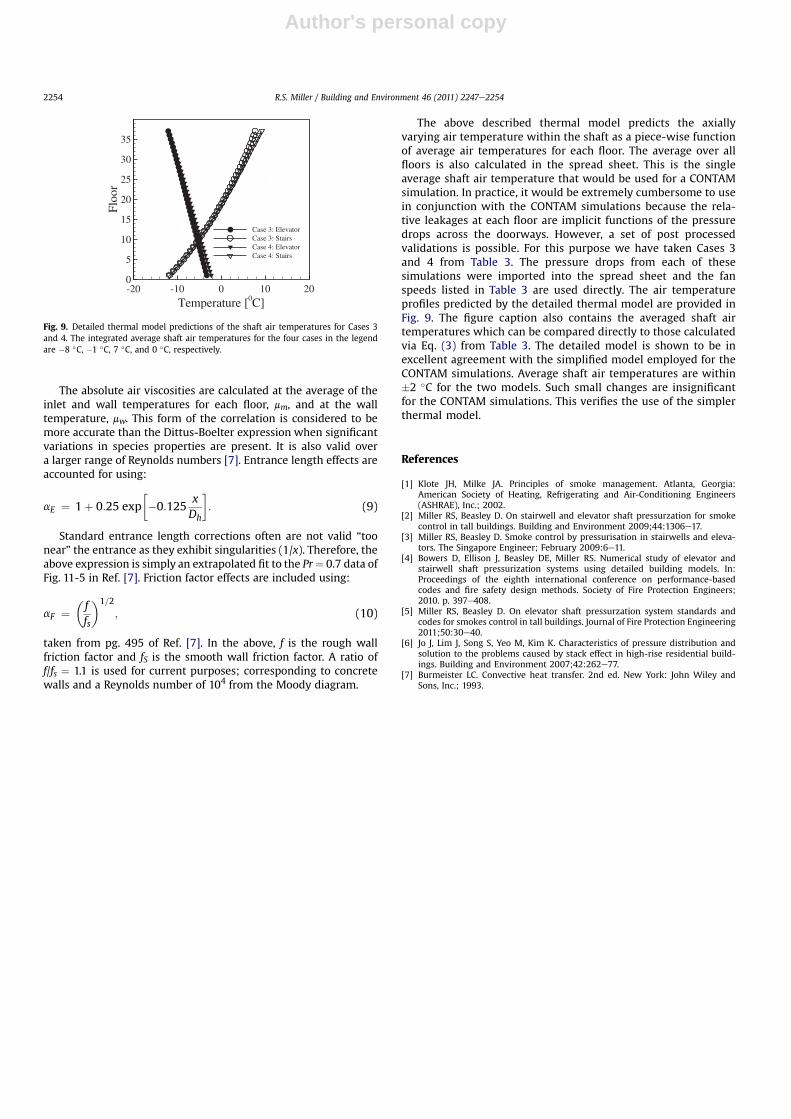
The above described thermal model predicts the axiallyvarying air temperature within the shaft as a piece-wise functionof average air temperatures for each floor. The average over allfloors is also calculated in the spread sheet. This is the singleaverage shaft air temperature that would be used for a CONTAMsimulation. In practice, it would be extremely cumbersome to usein conjunction with the CONTAM simulations because the rela-tive leakages at each floor are implicit functions of the pressuredrops across the doorways. However, a set of post processedvalidations is possible. For this purpose we have taken Cases 3and 4 from Table 3. The pressure drops from each of thesesimulations were imported into the spread sheet and the fanspeeds listed in Table 3 are used directly. The air temperatureprofiles predicted by the detailed thermal model are provided inFig. 9. The figure caption also contains the averaged shaft airtemperatures which can be compared directly to those calculatedvia Eq. (3) from Table 3. The detailed model is shown to be inexcellent agreement with the simplified model employed for theCONTAM simulations. Average shaft air temperatures are within�2 �C for the two models. Such small changes are insignificantfor the CONTAM simulations. This verifies the use of the simplerthermal model.
References
[1] Klote JH, Milke JA. Principles of smoke management. Atlanta, Georgia:American Society of Heating, Refrigerating and Air-Conditioning Engineers(ASHRAE), Inc.; 2002.
[2] Miller RS, Beasley D. On stairwell and elevator shaft pressurzation for smokecontrol in tall buildings. Building and Environment 2009;44:1306e17.
[3] Miller RS, Beasley D. Smoke control by pressurisation in stairwells and eleva-tors. The Singapore Engineer; February 2009:6e11.
[4] Bowers D, Ellison J, Beasley DE, Miller RS. Numerical study of elevator andstairwell shaft pressurization systems using detailed building models. In:Proceedings of the eighth international conference on performance-basedcodes and fire safety design methods. Society of Fire Protection Engineers;2010. p. 397e408.
[5] Miller RS, Beasley D. On elevator shaft pressurzation system standards andcodes for smokes control in tall buildings. Journal of Fire Protection Engineering2011;50:30e40.
[6] Jo J, Lim J, Song S, Yeo M, Kim K. Characteristics of pressure distribution andsolution to the problems caused by stack effect in high-rise residential build-ings. Building and Environment 2007;42:262e77.
[7] Burmeister LC. Convective heat transfer. 2nd ed. New York: John Wiley andSons, Inc.; 1993.
Temperature [0C]
Flo
or
-20 -10 0 10 200
5
10
15
20
25
30
35
Case 3: ElevatorCase 3: StairsCase 4: ElevatorCase 4: Stairs
Fig. 9. Detailed thermal model predictions of the shaft air temperatures for Cases 3and 4. The integrated average shaft air temperatures for the four cases in the legendare �8 �C, �1 �C, 7 �C, and 0 �C, respectively.
R.S. Miller / Building and Environment 46 (2011) 2247e22542254