kobe university repository : kernelof the monorail train plays an importa nt role in the seismic...
TRANSCRIPT

Kobe University Repository : Kernel
タイトルTit le
Effect of t rain dynamics on seismic response of steel monorail bridgesunder moderate ground mot ion
著者Author(s) Kim, Chul-Woo / Kawatani, Mitsuo
掲載誌・巻号・ページCitat ion Earthquake Engineering & Structural Dynamics,35(10):1225-1245
刊行日Issue date 2006-08
資源タイプResource Type Journal Art icle / 学術雑誌論文
版区分Resource Version author
権利Rights
This is a preprint of an art icle published in [Earthquake Engineering &Structural Dynamics, vol.35(10), 200608, p.1225 - 1245, Wiley]
DOI 10.1002/eqe.580
JaLCDOI
URL http://www.lib.kobe-u.ac.jp/handle_kernel/90000472
PDF issue: 2020-10-03

Effect of train dynamics on seismic response of steel monorail bridges under moderate ground motion
Chul-Woo Kim*,1, Mitsuo Kawatani 2
Department of Civil Engineering, Kobe University, 1-1 Rokkodai, Nada, Kobe 657-8501, Japan
SUMMARY
This study is intended to investigate the seismic response of steel monorail bridges using three-dimensional
dynamic response analysis. We particularly consider monorail bridge-train interaction when subjected to
ground motion that occurs with high probability. A monorail train car with two bogies with pneumatic tires
for running, steering and stabilizing wheels is assumed to be represented sufficiently by a discrete rigid
multi-body system with 15 degrees of freedom (DOFs). Bridges are considered as an assemblage of beam
elements with 6 DOFs at each node. Modal analysis is used for dynamic response analysis under moderate
earthquakes. The seismic response of an advanced monorail bridge that adopts a simplified structural
system and composite girders is investigated through comparison with seismic responses of a conventional
bridge. The acceleration response of a monorail train is also calculated to investigate the effect of structural
types of bridges on the train’s dynamic response during earthquakes. Results show that the seismic
responses of the advanced bridges are greater than those of the conventional monorail bridge because of the
simplified structural system and increased girder weight that is attributable to composite girders of the
advanced bridge. Moreover, the train on the advanced bridge shows greater dynamic response than that on
the conventional bridge. Observations reveal that the dynamic monorail train system acts as a damper on
the monorail bridge. That fact shows that the existing design, which considers a train as additional mass,
yields a conservative result.
KEY WORDS: bridge-train interaction; seismic response; three-dimensional analysis; monorail bridge
*Correspondence to: Chul-Woo Kim, Department of Civil Engineering, Kobe University, 1-1Rokkodai, Nada, Kobe 657-8501, Japan. Phone: +81-78-803-6383; FAX: +81-78-803-6069.
1 E-mail: [email protected] 2 E-mail: m- [email protected] 1 COE Researcher 2 Professor
1

INTRODUCTION
Traffic problems in major cities of the world during the last two decades have emphasized the considerable
need for new transportation systems. Straddle-type monorail systems (Figure 1) have been adopted for new
transportation systems throughout Japan in the cities of Tokyo, Osaka, Tama, Kita-Kyushu, and Naha.
Cost-efficiency is another important issue in modern bridge design. That situation has stimulated structural
engineers to create a concept of rationalized design strategy, even for monorail bridges. Therefore, a new
type of steel-concrete composite bridge for monorails (hereafter, advanced bridge) has been developed in
Japan. A simplified lateral bracing system in the advanced bridge constitutes the major difference from
conventional bridges. The composite steel girder with an RC tramway is another advanced concept to
enhance braking performance of monorail trains, even though it makes the advanced bridge heavier than a
conventional bridge. Actually, the authors have described in a recent report [1] that advanced bridges are
affected more easily by lateral loading effects than conventional bridges under a moving train. That fact,
together with the advanced scheme described above, suggests that the simplified lateral bracing system and
the composite track girder might engender problems related to seismic performance of the bridge.
Performance-based seismic design of bridges is an issue of great concern in countries, such as Japan,
which are located in earthquake-prone regions. The magnitude 6.6 earthquake that struck Niigata
Prefecture on the evening of 23 October 2004 was the most damaging earthquake to affect Japan since the
1995 Kobe earthquake. Roads, railways and other lifelines were compromised, engendering major
economic disruption. One Joetsu Shinkansen train that crosses this region in a north/south direction and
terminates in Niigata city was derailed just south of Nagaoka city by the earthquake. That event was, in
itself, an unprecedented shock to the civil engineering community.
In contrast to the railway system, the straddle-type monorail train employs steering and stabilizing
wheels that firmly grasp the track girder of monorail bridges. Consequently, the lateral motion and rolling
of a monorail train can affect the dynamic response of the bridge [2]. The live load attributable to the weight
of the monorail train plays an important role in the seismic design of monorail bridges because of the large
load of the train’s weight compared with the dead load of bridges. The dynamic system of the monorail train
is an important factor in the seismic response of the monorail bridge because the train has a complicated
dynamic system.
One question remaining to be answered is: What is the seismic behavior of the monorail bridges
considering bridge-train interaction when subjected to earthquakes? Another pertinent question is: What is
the difference of the seismic responses of conventional and advanced bridges?
Rather limited efforts have been devoted to the effects of train dynamics on the seismic resistance of
bridges, but some interesting studies have explored dynamic stability of railway trains and other vehicles
with ground motion. Kameda et al. [3] investigated the effect of vehicle loading on seismic responses of
highway bridges. That study concluded that the seismic response of the bridge can increase or decrease
according to the phase difference between the vehicle and bridge systems. Yang and Wu [4] investigated the
2

dynamic stability of trains moving over bridges that were shaken by an earthquake. Some studies have
examined dynamic stability of trains or other vehicles under seismic motions without considering
interaction with bridge structures. Miyamoto et al. [5] estimated the running safety of trains under
earthquakes on the condition that the train is set as stationary on the track. Maruyama and Yamazaki [6]
performed a seismic response analysis on the stability of running vehicles. However, few studies have
addressed the seismic response of the monorail bridge incorporating the bridge-train interactive effect.
This study is an attempt to investigate the seismic behavior of conventional and advanced monorail
bridges with steel piers incorporating interaction between bridges and trains under moderate ground
motions (called Level-I) by means of a three-dimensional dynamic response analysis. The Level-I ground
motions specified in the Design Specification of Highway Bridges of the Japan Road Association (hereafter,
JRA code) [7] are used as moderate ground motions that occur with high probability. As for the seismic
performance level under moderate ground motion, it is assumed that both important and standard bridges
should behave in an elastic manner without important damage under the Level-I ground motion according
to the JRA code.
DYNAMIC EQUATIONS OF MONORAIL BRIDGE-TRAIN INTERACTION WITH
EARTHQUAKE
Finite element (FE) method is used as a tool for idealizing bridges. Bridges are considered as an assemblage
of beam elements with six degrees of freedom (DOFs) at each node. Modal analysis is adopted for dynamic
response analysis under moderate earthquakes. The consistent mass system and Rayleigh damping are used
respectively to form the mass and damping matrices of the bridge model. A process known as Guyan
reduction [8] is used to improve the efficiency of calculation.
Train model
A monorail train car has two bogies with pneumatic tires for running, steering and stabilizing wheels. The
car’s dynamic behavior is assumed to be sufficiently represented by a discrete rigid multi-body system with
15 DOFs, as shown in Figure 2, where m indicates the mass, K is the spring constant, C is the damping
coefficient, and Z, Y and θ respectively indicate the vertical, lateral and rotational displacement. Details of
the notation and dynamic characteristics of the monorail train are summarized in Table I.
The equations of motion for a car in the train can be derived using Lagrange’s formulation as
0=∂∂
+∂∂
+∂∂
−⎟⎟⎠
⎞⎜⎜⎝
⎛∂∂
∂∂
i
d
i
e
ii aU
aU
aT
aT
t &&, (1)
where T is the kinetic energy, Ue is the potential energy of the system and Ud is the dissipation energy
attributable to damping of the system; ai is a generalized coordinate.
3

Modifying the energy equations for vehicles on a highway bridge [9] develops the kinetic energy,
potential energy and dissipation energy of the monorail car on a bridge. These are expressed as a set of
generalized coordinates as the following [2].
[
{ }⎥⎥⎦
⎤+++++
++++=
∑
∑
=
=
2
1
222
222
222
222
222
1
21111
21111
21111
21111
211112
1
iivzivzivyivyivxivxiviviviv
nv
vvzvzvyvyvxvxvvvv
IIIYmZm
IIIYmZmT
θθθ
θθθ
&&&&&
&&&&&
(2)
{ }
⎥⎥⎦
⎤+
⎢⎢⎣
⎡+++=
∑
∑ ∑∑∑
=
= = = =
2
1
2511511
1
2
1
2
1
2
11
244
233
2221
2112
1
ivivi
nv
v i j njjnvijnvijnvijnvijnvijnvijjnvijnvie
RK
RKRKRKRKU δδ
(3)
{ }
⎥⎥⎦
⎤+
⎢⎢⎣
⎡+++=
∑
∑ ∑∑∑
=
= = = =
2
1
2511511
1
2
1
2
1
2
11
244
233
2221
2112
1
ivivi
nv
v i j njjnvijnvijnvijnvijnvijnvijjnvijnvid
RC
RCRCRCRCU
&
&&&& δδ
(4)
In those equations, nv is the number of cars in monorail train, I is the mass moment of inertia, Rvimjn is the
relative displacement at springs and dampers, and δij is Kronecker’s delta. The subscript ν indicates the
number of monorail cars on the bridge. Subscript i is an index indicating the suspension position of a car of
monorail train (i=1 and 2 are the front and rear suspensions, respectively). Subscript j is the tire position in
a bogie (e.g. j=1 and 2 are the front and rear tires of the bogie system, respectively). In addition, n is an
index indicating either the left or right side of the train.
The relative displacement is definable in the following manner.
vxivyi
vyivxn
vyvxn
ivvjnvi ZZR λθλθλθ 11222112111 )1()1()1( −−−−−+−= (5)
jnivyivxn
vxivyj
ivjnvi VZR 20423222 )1()1( −−+−−= λθλθ (6)
423023 )1( vxivzj
jniivjnvi VYR λθ−+−= (7)
324024 vzivxjniivjnvi VYR λθ+−= (8)
vxivzi
vzvxivvjnvi YYR λθλθ 111112115 )1(−+−−= (9)
Therein, V0imjn denotes the relative displacement of the bridge and surface roughness at the contact points of
4

wheel positions.
The equation of motion for a traveling monorail train on a bridge can be expressed as
vvvvvvv fwKwCwM =++ &&& , (10)
where Mv, Cv and Kv respectively represent mass, damping and stiffness matrices of the train. In addition, fv
is the interaction force vector applied on the train, and wv indicates the displacement vector of the train.
Overdots represent the derivative with respect to time.
Bridge model
Equation (11) shows the equation of the forced vibration obtained for a bridge system under the moving
monorail train:
bbbbbbb fwKwCwM =++ &&& , (11)
where Mb, Cb and Kb respectively denote the mass, damping and stiffness matrices of the bridge. In
addition, fb is an external force vector; wb indicates the displacement vector of the bridge. Rayleigh
damping is adopted to form the damping matrix.
Monorail bridge-train interaction model
Considering the interaction force and wheel load at the contact points, the combination of Eqs. (10) and (11)
gives the equation of the forced vibration for a monorail bridge-train interaction system as
⎭⎬⎫
⎩⎨⎧
=⎭⎬⎫
⎩⎨⎧⎥⎦
⎤⎢⎣
⎡+
⎭⎬⎫
⎩⎨⎧⎥⎦
⎤⎢⎣
⎡+
⎭⎬⎫
⎩⎨⎧⎥⎦
⎤⎢⎣
⎡
v
b
v
b
v
bvbb
v
b
v
bvbb
v
b
v
b
SymSymSym ff
ww
KKK
ww
CCC
ww
M0M
... &
&
&&
&&, (12)
where Cbb, Cbv, Kbb and Kbv respectively indicate coupling damping and stiffness matrices of the
bridge-train interaction system, which will be time-dependent when the train starts to move. bf is the
external load vector caused by the moving monorail train on a bridge. vf is the dynamic wheel load vector
of a train.
Validity of the monorail bridge-train interaction system is verified through comparison with field test
data [2].
Monorail bridge-train interaction model subjected to ground motion
If the interaction system defined in Eq. (12) is subjected to ground motion, as would occur in an earthquake,
then the problem is solvable by considering an additional force input because of acceleration of the mass
5

that is governed by an absolute coordinate.
The equation of motion for an interactive system under an earthquake in the simplified matrix is
therefore
⎪⎭
⎪⎬⎫
⎪⎩
⎪⎨⎧
−−
=⎭⎬⎫
⎩⎨⎧⎥⎦
⎤⎢⎣
⎡+
⎭⎬⎫
⎩⎨⎧⎥⎦
⎤⎢⎣
⎡+
⎭⎬⎫
⎩⎨⎧⎥⎦
⎤⎢⎣
⎡
vgv
bgb
v
b
v
bvbb
v
b
v
bvbb
v
b
v
b
aa
SymSymSym MfMf
ww
KKK
ww
CCC
ww
M0M
&&
&&
&
&
&&
&&
..., (13)
where äg is the ground acceleration at the basement of bridge structures during an earthquake.
NUMERICAL MODELS
Monorail bridges
The general layout and the basic geometry of advanced and conventional bridges are presented in Figure 3.
Both bridges consist of two track girders with span lengths of 42.8 m. Steel bearings are adopted in the
monorail bridges. The advanced bridge adopts composite steel girders with RC tramways, whereas the
conventional bridge comprises steel girders. The mass of the superstructure of the advanced bridges is
200.56 tons and 146.32 tons for conventional bridges. Tables II and III respectively show properties of
advanced and conventional bridges.
Figure 4 shows that bridges adopt steel piers made of SM490Y structural steel with the rectangle
section. The pier is 15 m high. The cross-section is designed for Level-II ground motion with a low
probability of occurrence according to the JRA code. The bridge footings of the models are idealized as
springs. Table IV shows the spring constant used in the analysis. For the advanced bridge, the pier mass is
55.36 tons: 15.82 tons for the pier cap beam and 39.54 tons for the pier column. The pier’s mass of the
conventional bridge is 47.95 tons: 13.70 tons for the pier cap beam and 34.25 tons for the pier column.
Figure 5 shows the FE model for the bridges, which consist of two spans idealized by the beam element
with 6 DOFs. It also incorporates a train’s driving direction and observation points for displacement and
shear force responses at the span center and the bearing supporting the G1 girder of the first span,
respectively.
Ground motion
Two kinds of ground motions, so called Level-I and Level-II ground motions, are adopted in the JRA code
based on the seismic performance level of bridge structures. The Level-I ground motion is the moderate
design ground motion, which has a return probability of once or twice in the service life of the structure. For
the seismic performance under the Level-I ground motion both standard and important bridges should
behave in an elastic manner without essential structural damage. The Level-II ground motion indicates the
extreme design ground motion with low probability to occur, which is caused by plate boundary
6

earthquakes and inland earthquakes such as Kobe earthquake in 1995. For the seismic performance under
the Level-II ground motion the standard bridges should prevent critical failure, while the important bridges
should perform with limited damage.
The ground motion adopted in the seismic response analysis of monorail bridges is the Level-I ground
acceleration of the JRA code [7]. Two accelerograms according to the soil sites shown in Figure 6 are used
for analysis: the Group-I ground motion for the stiff soil site and the Group-II for the moderate soil site. The
frequency in the legend of spectra is linked with the dominant frequency of each bridge response during
earthquakes, as shown in the next section (Figures 8 and 9).
DYNAMIC RESPONSES OF MONORAIL BRIDGES AND TRAINS WITH GROUND MOTION
Three numerical examples are used to investigate the effect of the train’s dynamic system on seismic
responses of steel monorail bridges under earthquakes. How the train is considered in the numerical
example is shown in Figure 7 for the advanced bridge. The same concept is employed for the conventional
bridge. The first one is the monorail bridge model without a train on the bridge (Figure 7(a)). Figure 7(b)
shows that the second one is a model considering the train as an additional mass on the bridge model. It is
noteworthy that the monorail train, during operation, is assumed to have the mass of 34.4 tons/car (= 26.7
tons/empty car + 129 passengers × 0.06 ton/person). Figure 7(c) shows a third situation that illustrates the
interaction between a bridge and stationary train. The bridge-moving train interaction model shown in
Figure 7(d) is used to investigate the seismic response under the moving monorail train. The target speed is
3.9 m/s, which is the speed that the first car in the monorail train, composed of six cars, can travel the
observed bridge during Group-I ground motion of 25 seconds. Half of the mass of the adjacent girder is
considered in the analysis, as shown in Figure 7 to incorporate the inertia effect of the neighboring span:
50.14 tons and 36.58 tons for advanced and conventional bridges, respectively.
The dynamic response of each bridge is obtained by summing up to the mode related to the frequency
near 30 Hz: for the model ignoring the train’s mass, up to the 50th (29.8 Hz) and 40th (29.4 Hz) modes were
shown for advanced and conventional bridges respectively; up to the 57th (29.7 Hz) and 46th (29.4 Hz)
modes were considered respectively in advanced and conventional bridges for the model considering the
train as an additional mass. Newmark’s β method [10] is adopted to solve simultaneous differential
equations of the monorail bridge-train interaction system under earthquakes. The value of 0.25 is adopted
for β to obtain stable and accurate solutions. The damping constant of the monorail bridge during an
earthquake is assumed as 5%.
Eigenvalue analysis
Eigenvalue analyses were carried out to gain fundamental insight into the dynamic characteristics of the
bridges. Mode shapes and natural frequencies of the first five modes are listed in Table V. That table shows
that the first natural frequencies are 1.33 Hz and 1.54 Hz, respectively, for the advanced and conventional
7

bridge models without considering the train’s mass. Those values are 1.09 Hz and 1.15 Hz for each bridge
model considering the train as an additional mass. The natural frequencies in the parenthesis of Table V are
values taken from considering the train’s mass as an additional mass on the bridge. The first three modes are
in relation to the lateral bending of steel piers coupled with that of the track girders’. The vertical bending
modes of the track girders appear in the fourth and fifth modes.
Dynamic response of the bridges
The seismic responses of respective bridges are investigated as shown in Figure 8 to Figure 11, where the
displacement response of the first span center is summarized in Figures 8 and 9 according to ground motion.
The shear force at the observation with the ground motion is shown in Figures 10 and 11. Bridge responses
under traveling trains are also shown in each figure to provide information about the seismic responses of
bridges under moving trains. A noteworthy point here is that the model considering a traveling train
subsumes that the train starts to move and enter the bridge at the instant that an earthquake occurs, while the
model of a stationary train is affected by the six cars of the monorail train during an earthquake. For that
reason, it is difficult to compare the seismic responses of bridges interacting with the stationary train with
responses for a moving train, as shown in Figures 8–11.
As illustrated in Figures 8–9, both the absolute peak and RMS values of the displacement response of
the advanced bridge are greater than those of the conventional bridge with both ground motions. It indicates
that the advanced bridge with fewer lateral members and heavier track-girders than those of the
conventional bridge is easily vibrated in the transverse direction during earthquakes. Considering the effect
of the train mass on bridges as summarized in Figures 8(b) and 9(b), determining the train on bridges
provides greater seismic response than that with the model without the train shown in Figures 8(a) and 9(a)
because of the additional inertial effect of the train on bridges during earthquakes. Noteworthy results are
that the model that incorporates train dynamics (Figures 8(c), 8(d), 9(c) and 9(d)) tends to show less seismic
response than that which ignores the dynamic system of the train as shown in Figures 8(b) and 9(b). They
demonstrate that the bridge model considering the train as an additional mass provides a conservative
design.
Fourier amplitudes of displacement responses show that the bridge models that ignore the monorail
train are affected strongly by the dynamic component near 1.34 Hz and 1.49 Hz under the Group-I ground
motion for the advanced and conventional bridges, respectively. Similarly, under the Group-II ground
motion, 1.37 Hz and 1.49 Hz are dominant frequencies for the advanced and conventional bridges,
respectively. Those strong effects pertain because of the effect of the first natural frequency of each bridge
summarized in Table V (1.33 Hz and 1.54 Hz, respectively, for the advanced and conventional bridge
models without considering train’s mass; 1.09 Hz and 1.15 Hz, respectively, for the advanced and
conventional bridge models considering the train as an additional mass) together with the dynamic
component in relation to those frequencies shown in each accelerogram of Figure 6. On the other hand, the
Fourier amplitudes of the bridge models considering the train’s mass and the train as a dynamic system as
8

shown in Figures 8(b) to 8(d) as well as in Figures 9(b) to 9(d) demonstrate that the bridge response tends to
respond with lower dominant frequencies that are attributable to the increased mass of an external load such
as a monorail train.
It is noteworthy that, as stated in Eq.(12), the coefficient matrices Cbb, Cbv, Kbb, Kbv and wheel load
vector ( bf ) in Eq.(13) are affected by train’s spring and damping constants as well as the train’s position at
a time. It indicates that those matrices are time-variant when the train starts to move. On the other hand,
when the stationary train is on the bridge, those coefficients are time-invariant. Therefore bridge responses
under the moving train differ from those responses under the stationary train.
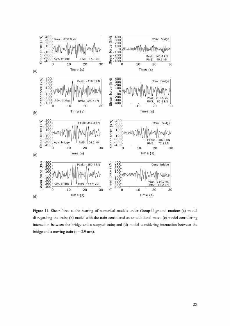
Shear force at the observation bearing during earthquakes is summarized in Figures 10 and 11
according to ground motions. The effects of the bridge type and a train on the shear force at the bearing are
similar to the tendency observed in the seismic displacement response of the bridge.
This study also examines the reason why the seismic response of the monorail bridge that incorporates
the bridge-train interaction tends to be lower than the response of the bridge model that incorporates the
train as an additional mass on a bridge. Figure 12, which shows the behavior of the advanced monorail
bridge and train at the times of 11.8 s and 12.2 s under Group-II ground motion, answers that question. The
existence of phase between train and bridge systems in ground motion is observed in Figure 12. As shown
in Figure 12(a), the upper part of the train (train body) remains on the right part, whereas the bridge
completely deforms to the left-hand side at 11.8 s; a reverse tendency is visible in Figure 12(b).
It clearly illustrates that the dynamic system of the train might act as a damper during earthquakes.
Observations show that the phase difference depending on dynamic characteristics of the monorail train and
bridge system helps to reduce the inertia effect during earthquakes.
Dynamic response of train
The straddle-type monorail bridge consists of elevated narrow track girders. Passengers in a straddle-type
monorail train feel closer to an open space and thereby become more sensitive to vibration with a visual
connection than do passengers in a railway train or a vehicle on elevated viaducts. The dynamic response of
a monorail train on a monorail bridge under ground motion is examined next.
Figures 13 and 14 show the respective acceleration responses taken from the train’s body under Group-I
and Group-II ground motions. The observation point during the train traveling with ground motion is the
floor on the front axle of the first car. The floor on the rear axle of the second car positioned on the center of
the second span is the observation point for the train standing on the bridge. Acceleration responses of the
monorail train on the advanced bridge are slightly greater than those of the train on the conventional bridge
under earthquakes.
CONCLUSIONS
Seismic response analyses of advanced and conventional monorail bridges were undertaken to investigate
9
the effect of the dynamic system of a monorail train on the bridge responses under the Level-I ground
motions specified in the JRA code. Dynamic responses of monorail trains on monorail bridges with ground
motions were also examined. Some important conclusions can be summarized as follows:
1) Seismic responses of the advanced bridge, such as the displacement at the span center and the shear
force at the bearing, are greater than those of the conventional bridge because of the heavier girder
weight and less lateral bracing of the advanced bridge than of the conventional bridge. This fact
emphasizes the need for detailed inspection of seismic performance for advanced bridges under
extreme ground motion, which dominates the seismic design.
2) The model that incorporates train dynamics tends to reduce the seismic response in comparison with
the bridge model considering the train as an additional mass. One reason for that phenomenon is that
the phase difference depending on dynamic characteristics of the monorail train and bridge system
helps to reduce the inertia effect during earthquakes.
3) Consideration of the dynamic interaction between the bridge and train during seismic design can
provide an economic design under the ground motions specified in the JRA code. In other words,
existing design methods, which consider the train as an additional mass, provide a conservative result.
4) Acceleration responses of monorail trains on advanced bridges are slightly greater than those of trains
on conventional bridges under earthquakes.
It is difficult to say, however, that the code specified ground motions are appropriate to examine even
the train response because the code specified ground motions are directly connected with the seismic
design and response of bridge structures. Future study needs, therefore, further investigations using
various seismic records to make a general conclusion for the train dynamics on the seismic response of
bridges.
ACKNOWLEDGMENTS
This study is supported by the Japan Society of the Promotion of Science (Grant-in-Aid for Scientific
Research (B) under project No. 17360213) which is gratefully acknowledged. The authors are also grateful
to Mr. T. Kanbara, a former graduate student of Osaka University of Japan, for his help in designing the
steel piers. Additional thanks go to Mr. F. Taniguchi, a graduate student of Kobe University of Japan, for his
assistance in the simulation.
REFERENCES
1. Lee CH, Kim CW, Kawatani M, Nishimura N, Kamizono T. Dynamic response analysis of monorail
bridges under moving trains and riding comfort of trains. Engineering Structures 2005; 27/14:
1999-2013.
2. Lee CH, Kawatani M, Kim CW, Nishimura N, Kobayashi Y. Dynamic response of a monorail under a
moving train. Journal of Sound and Vibration. (accepted for publication)
10

3. Kameda H, Murono Y, Nanjou A, Sasaki N. Earthquake response of highway bridges under
bridge-vehicle system. Journal of Structural Mechanics and Earthquake Engineering (JSCE) 1999;
626/I-48: 93-106. (in Japanese)
4. Yang YB, Wu YS. Dynamic stability of trains moving over bridges shaken by earthquakes. Journal of
Sound and Vibration 2002; 258: 65-94.
5. Miyamoto T, Ishida H, Matsuo M. Running safety of railway vehicle as earthquake occurs. QR of RTRI
1997; 38/3: 117-122.
6. Maruyama Y, Yamazaki F. Seismic response analysis on the stability of running vehicles. Earthquake
Engineering and Structural Dynamics 2002; 31: 1915-1932.
7. Japan Road Association. Specifications for Highway Bridges, Part V: Seismic Design. JRA: Tokyo,
Japan, 2002.
8. Guyan RJ. Reduction of stiffness and mass matrices. AIAA J 1965; 3(2): 380.
9. Kim CW, Kawatani M, Kim KB. Three-dimensional dynamic analysis for bridge-vehicle interaction
with roadway roughness. Computers and Structures 2005; 83: 1627-1645.
10. Newmark NM. A Method of computation for structural dynamics. J. of Eng. Mech. Div. (ASCE) 1970;
96: 593-620.
Table I. Monorail car properties: no passengers.
Parameter Notation Value
Mass (ton)
Body Bogie
mv11 mv21( = mv22)
14.22 6.20
Spring constant (kN/m)
Air suspension (vertical) Traveling wheels Steering wheels Stabilizing wheels Air suspension (lateral)
Kv1111( = Kv1112 = Kv2111 = Kv2112) Kv1211 ( = Kv1212 = Kv1221 = Kv1222 = Kv2211 = Kv2212 = Kv2221 = Kv2222) Kv1311( = Kv1312 = Kv1321 = Kv1322 = Kv2311 = Kv2312 = Kv2321 = Kv2322) Kv1411( = Kv1412 = Kv2411 = Kv2412) Kv1511( = Kv2511)
900.0 5170.0 6370.0 6370.0
980.0
Damping coefficient (kN·s/m)
Air suspension (vertical) Traveling wheels Steering wheels Stabilizing wheels Air suspension (lateral)
Cv1111( = Cv1112 = Cv2111 = Cv2112) Cv1211( = Cv1212 = Cv1221 = Cv1222 = Cv2211 = Cv2212 = Cv2221 = Cv2222) Cv1311( = Cv1312 = Cv1321 = Cv1322 = Cv2311 = Cv2312 = Cv2321 = Cv2322) Cv1411( = Cv1412 = Cv2411 = Cv2412) Cv1511( = Cv2511)
22.8 26.1
185.5 185.5 333.6
Geometry (m)
λvx1( = λvx2) λvx3
λvx4
λvy1
λvy2 λvy3
λvy4 λvz1
λvz2 λvz3
4.80 0.75 1.25 1.490 1.025 0.7823 0.2 0.885 0.630 1.085
11
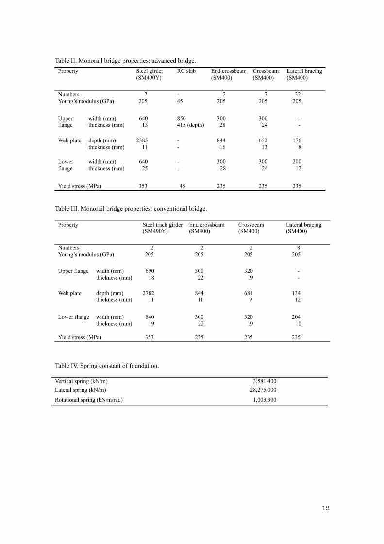
Table II. Monorail bridge properties: advanced bridge. Property Steel girder
(SM490Y) RC slab End crossbeam
(SM400) Crossbeam (SM400)
Lateral bracing(SM400)
Numbers Young’s modulus (GPa)
2 205
- 45
2 205
7 205
32 205
Upper flange
width (mm) thickness (mm)
640 13
850 415 (depth)
300 28
300 24
- -
Web plate
depth (mm) thickness (mm)
2385 11
- -
844 16
652 13
176 8
Lower flange
width (mm) thickness (mm)
640 25
- -
300 28
300 24
200 12
Yield stress (MPa) 353 45 235 235 235
Table III. Monorail bridge properties: conventional bridge.
Property Steel track girder (SM490Y)
End crossbeam (SM400)
Crossbeam (SM400)
Lateral bracing (SM400)
Numbers Young’s modulus (GPa)
2 205
2 205
2 205
8 205
Upper flange
width (mm) thickness (mm)
690 18
300 22
320 19
- -
Web plate
depth (mm) thickness (mm)
2782 11
844 11
681 9
134 12
Lower flange width (mm)
thickness (mm) 840
19 300
22 320
19 204
10 Yield stress (MPa) 353 235 235 235
Table IV. Spring constant of foundation.
Vertical spring (kN/m) 3,581,400 Lateral spring (kN/m) 28,275,000
Rotational spring (kN·m/rad) 1,003,300
12

Table V. First five natural modes and frequencies of monorail bridges.
Mode No. Advanced bridge Conventional bridge
1
2
3
4
5
* Disregarding the train’s mass and ** Considering train’s mass.
13

Figure 1. Configuration of straddle-type monorail train on the track girder.
Figure 2. Idealized monorail car of 15 DOFs.
14

(a)
23000
3700
99002700 2700 2700
99002700
4400042800600 600
unit: mm
3700105640105
2800
2385
415
850
unit: mm
585400
900
RC
(b) 3700
2900
100640100
900
1400
850
1250
1650
80 690 80
unit: mm
85330540445
6 @ 5400 = 324005200 5200
4400042800600 600
unit: mm
3700
Figure 3. Configuration of monorail bridges: (a) advanced bridge; and (b) conventional bridge.
15

(a)
1500
0
1315
014
0045
0
18502100
1850 2600 2600442 4 @ 429 = 1716
2826
2100
427.
5
27
222
214
y
x
427.
5
442
3 @
415
=12
45
(Lateral direction)
28 (Traveling direction)
Cross sectionElevation view
unit: mm
(b)
1500
1850 2000
1850
1500
0
1315
014
0045
0
2 000340 4 @ 330 = 1320
28
1500
3 @
294
= 8
8230
9
26
32220
200
y
x
340
28
309
(Lateral direction)
(Traveling direction)
Cross sectionElevation view
unit: mm
Figure 4. Configuration of steel piers: (a) advanced bridge; and (b) conventional bridge.
16

(a)
Observation point:span centre
Observation point:bearing
Observation point:span centre
Observation point:bearing
Driving direction
G1
G2
(b)
Driving direction
Observation point:span centre
Observation point:bearing
Observation point:span centre
Observation point:bearing
G1
G2
Figure 5. FE models of monorail bridges: (a) advanced bridge; and (b) conventional bridge.
17

(a) Ac
cele
ratio
n (m
/s2 )
0 5 10 15 20 25 30-2.0-1.5-1.0-0.50.00.51.01.52.0
Time (s)
Level-I (Group-I)
Peak: 1.02 m/s2
0.1 1 100.00
0.02
0.04
0.06
0.08
0.10
Four
ier a
mp.
(m/s
)
Frquency (Hz)
1: 0.85 Hz2: 1.00 Hz3: 1.17 Hz4: 1.34 Hz5: 1.49 Hz 1
23
45
(b)
Acc
eler
atio
n (m
/s2 )
0 5 10 15 20 25 30-2.0-1.5-1.0-0.50.00.51.01.52.0
Time(s)
Level-I (Group-II)
Peak: 1.18 m/s2
0.1 1 100.00
0.02
0.04
0.06
0.08
0.10
Four
ier a
mp.
(m/s
)
Frequency (Hz)
1: 0.85 Hz2: 1.00 Hz3: 1.20 Hz4: 1.37 Hz5: 1.48 Hz
1
2
3
4
5
Figure 6. Accelerograms of JRA code (Level-I) and Fourier amplitude of acceleration: (a) stiff soil site
(Group-I); and (b) moderate soil sites (Group-II).
18

(a)
: Mass effect of adjacent girder (50.14 ton and 36.58 ton respectively for advanced and conventional type bridges).
(b)
: Mass effect of a car (2 @ 17.22 ton = 34.44 ton)
: Mass effect of adjacent girder (50.14 ton and 36.58 ton respectively for advanced and conventional type bridges).
(c)
: Monorail train with 15DOFs
: Mass effect of adjacent girder (50.14 ton and 36.58 ton respectively for advanced and conventional type bridges).
(d)
: Monorail train with 15DOFs
: Mass effect of adjacent girder (50.14 ton and 36.58 ton respectively for advanced and conventional type bridges).
...
Driving direction
Figure 7. Models for numerical example: (a) disregarding the train’s mass; (b) considering the train’s mass;
(c) considering bridge-stationary train interaction; and (d) considering bridge-moving train interaction.
19

(a)0 10 20 30
-80-60-40-20
020406080
Dis
pl. (
mm
)
Time (s)
Peak: -38.2 mmRMS: 14.2 mm
Adv. bridge
0 1 2 3 4 50
5
10
15
Frequency (Hz)Fourier
am
p.
(mm
. s)
1.34 Hz
0 10 20 30-80-60-40-20
020406080
Dis
pl.
(mm
)
Time (s)
Peak: -27.3 mmRMS: 7.6 mm
Conv. bridge
0 1 2 3 4 50
5
10
15
Frequency (Hz)Fourier
am
p. (m
m. s
)
1.49 Hz
(b)0 1 2 3 4 5
0
5
10
15
Frequency (Hz)Fourier
amp. (m
m. s
)1.17 Hz
0 10 20 30-80-60-40-20
020406080
Dis
pl.
(mm
)
Time (s)
Peak: -55.5 mmRMS: 16.3 mm
Adv. bridge
0 10 20 30-80-60-40-20
020406080
Dis
pl. (
mm
)
Time (s)
Peak: -45.9 mmRMS: 16.3 mm
Conv. bridge
0 1 2 3 4 50
5
10
15
Frequency (Hz)Fourier
amp. (m
m. s
)
1.17 Hz
(c)0 10 20 30
-80-60-40-20
020406080
Dis
pl.
(mm
)
Time (s)
Peak: -52.1 mmRMS: 14.5 mm
Adv. bridge
0 1 2 3 4 50
5
10
15
Frequency (Hz)Fourier
am
p. (m
m. s
)
1.00 Hz
0 1 2 3 4 50
5
10
15
Frequency (Hz)Fourier
am
p. (m
m. s
)
1.17 Hz
0 10 20 30-80-60-40-20
020406080
Dis
pl.
(mm
)
Time (s)
Peak: -41.3 mmRMS: 11.1 mm
Conv. bridge
(d) Time (s)0 10 20 30
-80-60-40-20
020406080
Dis
pl. (
mm
)
Peak: -39.7 mmRMS: 12.4 mm
Adv. bridge
0 1 2 3 4 50
5
10
15
Frequency (Hz)Fourier
am
p. (m
m. s
)
1.00 Hz1.17 Hz
0 10 20 30-80-60-40-20
020406080
Dis
pl. (
mm
)
Time (s)
Peak: -27.9 mmRMS: 8.7 mm
Conv. bridge
0 1 2 3 4 50
5
10
15
Frequency (Hz)Fourier
am
p. (m
m. s
)
1.17 Hz1.00 Hz
Figure 8. Lateral displacement at the first span center under Group-I ground motion and Fourier amplitude
of displacement of monorail bridges: (a) model disregarding the train; (b) model with the train considered
as an additional mass; (c) model considering interaction between the bridge and a stopped train; and (d)
model considering interaction between the bridge and a moving train (v = 3.9 m/s).
20

(a)0 10 20 30
-80-60-40-20
020406080
Dis
pl. (
mm
)
Time (s)
Peak: 49.7 mmRMS: 16.0 mm
Adv. bridge
0 1 2 3 4 50
5
10
15
Frequency (Hz)Fourier
am
p.
(mm
. s)
1.37 Hz
0 10 20 30-80-60-40-20
020406080
Dis
pl. (
mm
)
Time (s)
Peak: 34.2 mmRMS: 11.4 mm
Conv. bridge
0 1 2 3 4 50
5
10
15
Frequency (Hz)Fourier
am
p. (m
m. s
)
1.49 Hz
(b)0 10 20
-80-60-40-20
020406080
Dis
pl. (
mm
)
Time (s)
Peak: 68.2 mmRMS: 19.1 mm
Adv. bridge
30 0 1 2 3 4 50
5
10
15
Frequency (Hz)Fourier
amp. (m
m. s
)
1.02 Hz1.20 Hz
0 10 20 30-80-60-40-20
020406080
Dis
pl. (
mm
)
Time (s)
Peak: 58.3 mmRMS: 17.3 mm
Conv. bridge
1.02 Hz
1.20 Hz
0 1 2 3 4 50
5
10
15
Frequency (Hz)Fourier
am
p. (m
m. s
)
(c)0 1 2 3 4 5
0
5
10
15
Frequency (Hz)Fouri
er a
mp. (m
m. s
)
1.00 Hz
0 10 20 30-80-60-40-20
020406080
Dis
pl. (
mm
)
Time (s)
RMS: 18.8 mm
Peak: -62.3 mmAdv. bridge
0 1 2 3 4 50
5
10
15
Frequency (Hz)Fou
rier
amp. (m
m. s
)
1.00 Hz
0 10 20 30-80-60-40-20
020406080
Dis
pl. (
mm
)
Time (s)
Peak: -46.5 mmRMS: 14.4 mm
Conv. bridge
(d)0 1 2 3 4 5
0
5
10
15
Frequency (Hz)
Fourier
am
p.
(mm
. s)
1.00 Hz
0 10 20 30-80-60-40-20
020406080
Dis
pl. (
mm
)
Time (s)
Peak: 58.4 mm
RMS: 18.6 mm
Adv. bridge
0 10 20 30-80-60-40-20
020406080
Dis
pl. (
mm
)
Time (s)
Peak: 43.8 mmRMS: 12.6 mm
Conv. bridge
0 1 2 3 4 50
5
10
15
Frequency (Hz)Fou
rier
amp. (m
m. s
)
1.00 Hz
Figure 9. Lateral displacement at the first span center under Group-II ground motion and Fourier amplitude
of displacement of monorail bridges: (a) model disregarding the train; (b) model with the train considered
as an additional mass; (c) model considering interaction between the bridge and a stopped train; and (d)
model considering interaction between the bridge and a moving train (v = 3.9 m/s).
21

(a)
0 10 20 30-400-300-200-100
0100200300400
Shea
r fo
rce
(kN
)
Time (s)
Peak: 242.0 kNRMS: 78.1 kN
Adv. bridge
0 10 20 30-400-300-200-100
0100200300400
Shea
r fo
rce
(kN
)
Time (s)
Peak: -118.3 kNRMS: 32.0 kN
Conv. bridge
-400-300-200-100
0100200300400
(b)
0 10 20 30Shea
r fo
rce
(kN
)
Time (s)
Peak: 341.3 kNRMS: 90.5 kN
Adv. bridge
0 10 20 30-400-300-200-100
0100200300400
Shea
r fo
rce
(kN
)
Time (s)
Peak: -234.5 kNRMS: 81.5 kN
Conv. bridge
-400-300-200-100
0100200300400
(c)
0 10 20 30
Shea
r fo
rce
(kN
)
Time (s)
Peak: 284.1 kNRMS: 80.0 kN
Adv. bridge
0 10 20 30-400-300-200-100
0100200300400
Shea
r fo
rce
(kN
)
Time (s)
Peak: -205.3 kNRMS: 53.4 kN
Conv. bridge
-400-300-200-100
0100200300400
(d)
0 10 20 30Shea
r fo
rce
(kN
)
Time (s)
Peak: 246.0 kNRMS: 69.6 kN
Adv. bridge
0 10 20 30-400-300-200-100
0100200300400
Shea
r fo
rce
(kN
)
Time (s)
Peak: -122.3 kNRMS: 45.5 kN
Conv. bridge
Figure 10. Shear force at the bearing of numerical models under Group-I ground motion: (a) model
disregarding the train; (b) model with the train considered as an additional mass; (c) model considering
interaction between the bridge and a stopped train; and (d) model considering interaction between the
bridge and a moving train (v = 3.9 m/s).
22
(a)
0 10 20 30-400-300-200-100
0100200300400
Shear
forc
e (
kN)
Time (s)
Peak: -280.8 kN
RMS: 87.7 kNAdv. bridge
0 10 20 30-400-300-200-100
0100200300400
Shea
r fo
rce
(kN
)
Time (s)
Peak: 140.8 kNRMS: 48.7 kN
Conv. bridge
-400-300-200-100
0100200300400
(b)
0 10 20 30Shear
forc
e (k
N)
Time (s)
Peak: -416.3 kN
RMS: 106.7 kNAdv. bridge
0 10 20 30-400-300-200-100
0100200300400
Shea
r fo
rce (
kN
)Time (s)
Peak: 281.5 kNRMS: 86.8 kN
Conv. bridge
3-400-300-200-100
0100200300400
(c)
0 10 20 0Shear
forc
e (k
N)
Time (s)
Peak: 347.8 kN
RMS: 104.2 kNAdv. bridge
0 10 20 30-400-300-200-100
0100200300400
Shear
forc
e (
kN
)
Time (s)
Peak: -286.2 kNRMS: 72.9 kN
Conv. bridge
-400-300-200-100
0100200300400
(d)
0 10 20 30Shea
r fo
rce (
kN
)
Time (s)
Peak: -350.4 kN
RMS: 107.2 kNAdv. bridge
0 10 20 30-400-300-200-100
0100200300400
Shear
forc
e (
kN)
Time (s)
Peak: 234.0 kNRMS: 68.2 kN
Conv. bridge
Figure 11. Shear force at the bearing of numerical models under Group-II ground motion: (a) model
disregarding the train; (b) model with the train considered as an additional mass; (c) model considering
interaction between the bridge and a stopped train; and (d) model considering interaction between the
bridge and a moving train (v = 3.9 m/s).
23

(a)
t = 11.8 s
Train
Monorailbridge
0 5 10 15 20 25 30
-1.0-0.5
0.0
0.51.0
1.5
Time (s)
Gro
und
Acc
. (m
/s2
)
11.8 s
(b)
t = 12.2 s
Train
Monorailbridge
0 5 10 15 20 25 30
-1.0
-0.5
0.0
0.5
1.0
1.5
Time (s)
Gro
und
Acc
. (m
/s2
)
12.2 s
Figure 12. Phase motion of monorail train and bridge under Group-II ground motion: (a) at time t=11.8 s;
and (b) at time t=12.2 s.
24

(a)
Peak: 2.98 m/s2
RMS: 0.81 m/s2
0 10 20 3-4.0
-2.0
0.0
2.0
4.0
0
Acc
. (m
/s2 )
Time (s)
Standing onadv. bridge
Peak: 2.62 m/s2
RMS: 0.67 m/s2
0 10 20 30-4.0
-2.0
0.0
2.0
4.0
Acc
. (m
/s2)
Time (s)
Standing onconv. bridge
3-4.0
-2.0
0.0
2.0
4.0
(b)
0 10 20 0
Acc
. (
m/s
2)
Time (s)
Peak: -2.42 m/s2
RMS: 0.78 m/s2
Running onadv. bridge
Period of the observed carrunning on the bridge
0 10 20 30
-4.0
-2.0
0.0
2.0
4.0
Acc
. (m
/s2)
Time (s)
Peak: 3.04 m/s2
RMS: 0.75 m/s2
Running onconv. bridge
Period of the observed carrunning on the bridge
Figure 13. Acceleration of the observation car on monorail bridges under Group-I ground motion: (a) floor
on the rear axle of the second car of the train standing on a bridge; and (b) floor on the front axle of the head
car of the train running on a bridge (v = 3.9 m/s).
(a)
Peak: 4.03 m/s2
RMS: 1.14 m/s2
0 10 20 30-4.0
-2.0
0.0
2.0
4.0
Acc
. (m
/s2)
Time (s)
Standing onadv. bridge
Peak: 3.27 m/s2
RMS: 0.94 m/s2
0 10 20 30-4.0
-2.0
0.0
2.0
4.0
Acc
. (m
/s2)
Time (s)
Standing onconv. bridge
-4.0
-2.0
0.0
2.0
4.0
(b)
0 10 20 30
Acc
. (m
/s2 )
Time (s)
RMS: 0.96 m/s2Peak: -3.14 m/s2
Running on adv. bridge
Period of the observed carrunning on the bridge
Period of the observed carrunning on the bridge
0 10 20 30-4.0
-2.0
0.0
2.0
4.0
Acc
. (m
/s2 )
Time (s)
Peak: 2.71 m/s2
RMS: 0.85 m/s2
Running on conv. bridge
Figure 14. Acceleration of the observation car on monorail bridges under Group-II ground motion: (a) floor
on the rear axle of the second car of the train standing on a bridge; and (b) floor on the front axle of the head
car of the train running on a bridge (v = 3.9 m/s).
25