pv555
TRANSCRIPT

7/25/2019 pv555
http://slidepdf.com/reader/full/pv555 1/8
ISSN (Online) 2393-8021ISSN (Print) 2394-1588
International Advanced Research Jo urnal in Science, Engineering and Techno logy (IARJSET)
National Conferen ce on Renewable Energy and Enviro nm ent (NCREE-2015)
IMS Engineering College, Ghaziabad
Vol. 2, Special Issue 1, May 2015
Copyright to IARJSET DOI 10.17148/IARJSET 77
STABILITY ENHANCEMENT OF SINGLE
MACHINE INFINITE BUS SYSTEM USING
SOLAR PV CELLGyanesh Singh
Assistant Professor EN deptt. IMS Engg College Ghaziabad .
ABSTRACT: The aim of this work is to study the dynamic performance and stability enhancement of Single Machine
Infinite Bus System (SMIB) using solar pv cell. HPFC is an advanced FACTS controller which can be installed in a
transmission line between the two electrical areas. The main advantage using HPFC is that it can be used to replace or
supplement existing equipments. In the present thesis the Phillips-Heffron Model of SMIB Systems are presented. A proposed model of HPFC is presented and incorporated with SMIB models for analysis of the enhancement of stability.
All these models are simulated using MATLAB/SIMULINK. Simulation results show that the designed controller has
an excellent capability in damping power system oscillations if HPFC parameters are selected carefully. The results
when compared to that of existing FACTS controllers show that HPFC gives better performance. The significance of
the results are better stability and constant power supply.
Keywords: Model of SMIB Systems, FACTS controllers, Model of HPFC, MATLAB/SIMULINK. Simulation
POWER SYSTEM STABILITY
1.1 INTRODUCTION
Power system stability has been recognized as an
important problem for secure system operation since the1920s. Many major blackouts are caused by power system
instability. As power systems have evolved throughcontinuing growth in interconnections, use of new
technologies and controls, and the increased operation in
highly stressed conditions, different forms of system
instability have emerged. A clear understanding of
different types of instability and how they are interrelated
is essential for the satisfactory design and operation of power systems.
1.2 DEFINITION OF POWER SYSTEM STABILITY
Power system stability is the ability of an electric
power system, for a given initial operating condition, toregain a state of operating equilibrium after being
subjected to a physical disturbance as in Fig.1.1 with most
system variables bounded so that practically the entire
system remains intact.
Fig.1.1 Illustration of the Definition of Stability
1.3 HYBRID POWER FLOW CONTROLLER A block diagrammatic view of the envisioned
typical HPFC application is shown in Fig.1.3. The HPFC
is installed on a transmission line that connects two
electrical areas. In general, its point of installation will be
“within” the transmission line, i.e. at some distance fromstrong voltage busses.
7/25/2019 pv555
http://slidepdf.com/reader/full/pv555 2/8
ISSN (Online) 2393-8021ISSN (Print) 2394-1588
International Advanced Research Jo urnal in Science, Engineering and Techno logy (IARJSET)
National Conferen ce on Renewable Energy and Enviro nm ent (NCREE-2015)
IMS Engineering College, Ghaziabad
Vol. 2, Special Issue 1, May 2015
Copyright to IARJSET DOI 10.17148/IARJSET 78
Fig.1.3 Hybrid Power Flow Controller- Typical
Application
Central to the HPFC’s topology is the shuntconnected source of reactive power denoted as BM in Fig.1.8 a switched capacitor bank, or a static VAr
compensator. Next, there are two voltage – sourced
converters (VSCX and VSCY) connected in series with the
associated line segments using coupling transformers. The
converters share a common DC circuit, coupling each
other’s DC terminals. The DC circuit permits exchange of
active power between the converters. By controlling the
magnitudes and angles of voltages supplied by the
converters, the flow of active power through the line and
the amounts of reactive power supplied to each line
segment can be simultaneously and independently
controlled. The control of the shunt connected reactiveelement is coordinated with the control of converters to
supply the bulk of the total required reactive power.
A basic comparison of this topology with that of the
UPFC highlights the important features of this new circuit.
In short, UPFC’s shunt converter is substituted by a(presumably existing) switched capacitor, while its series
converter is split into two “half -sized” ones, installed on
each side of the shunt device. Such topological
arrangement results in operating characteristics similar to
those of the UPFC, while achieving considerable savings
in the total required converter MVA ratings. The hybrid
configuration for the control of power flow is introduced
here [27]. This concept has been extended with the help oftwo VSCs.
1.9 HEFFRON- PHILIPSMODEL OF SMIB POWER
SYSTEM
The SMIB system considered is a synchronous
generator with type 1 excitation system connected to an
infinite bus through a transmission line. The non linear
generator equations are linearized around a nominal
operating point to obtain a simplified linear model of
SMIB system as shown in Fig. 1.4. The block diagrammodel shown in Fig.1.4 is known as Heffron-Philips
model. By introducing a number of new constant a very
compact notation is achieved. The model shall enable theuser to directly implement a usable representation of an
SMIB system, including the mechanical dynamics, fieldwinding and excitation system. This implementation can
be used directly for stability studies. The constants K 1 to
K 6 is incorporated in Phillips-Heffron model, which
govern the system configuration and operation are as
follows.-
K 1={E bEqoCos δo/(Xe+Xq)}+{E bIq0sinδ0(Xq-Xd’)/(Xe+Xd’)
(1.12)
K 2={iqo(Xe+Xq)/(Xe+Xd’)}
(1.13)
K 3=(Xe+Xd’)/(Xe+Xd) (1.14)
K 4=E bsinδ0(Xd-Xd’)/(Xe+Xd’) (1.15)
K 5={(-XqVdoE bcosδ0)/((Xe+Xq)Vto)}-
{Xd’VdoE bsinδ0/((Xe+Xd’)Vto)} (1.16)
K 6=XeVqo/[((Xe+Xd’)Vto)] (1.17)
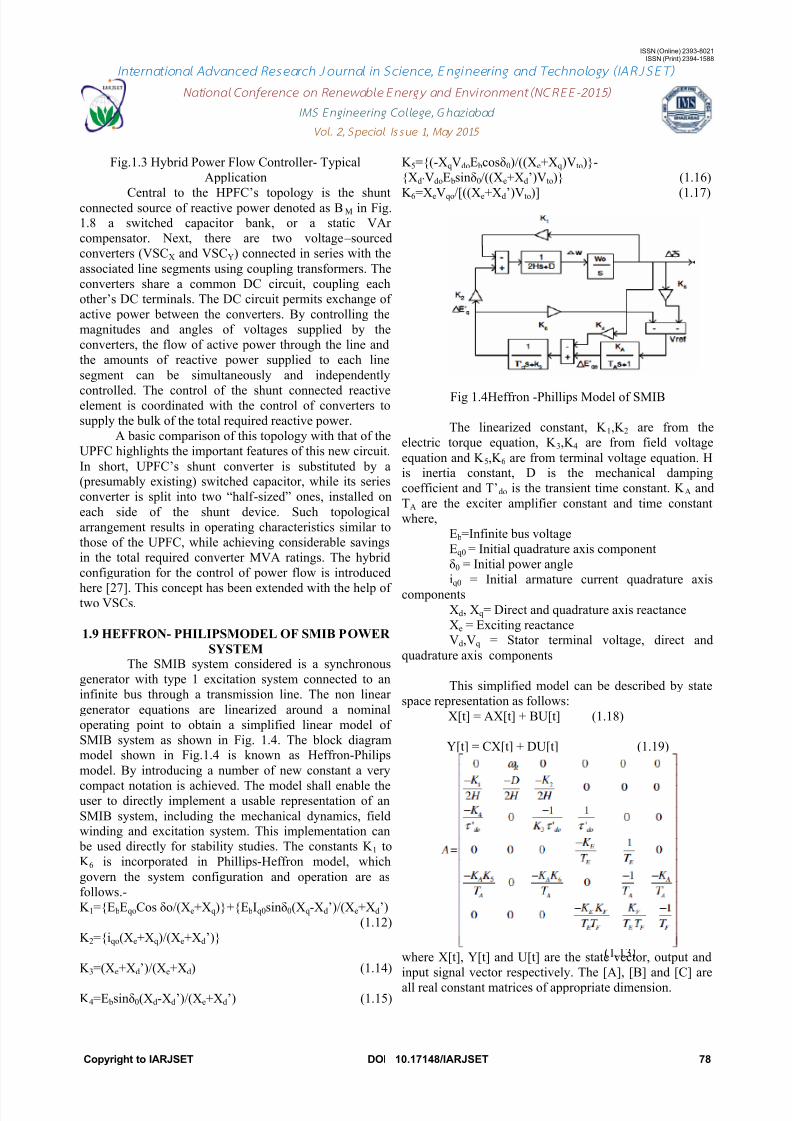
Fig 1.4Heffron -Phillips Model of SMIB
The linearized constant, K 1,K 2 are from the
electric torque equation, K 3,K 4 are from field voltage
equation and K 5,K 6 are from terminal voltage equation. His inertia constant, D is the mechanical damping
coefficient and T’do is the transient time constant. K A and
TA are the exciter amplifier constant and time constant
where,
E b=Infinite bus voltage
Eq0 = Initial quadrature axis component
δ0 = Initial power angle
iq0 = Initial armature current quadrature axis
components
Xd, Xq= Direct and quadrature axis reactance
Xe = Exciting reactanceVd,Vq = Stator terminal voltage, direct and
quadrature axis components
This simplified model can be described by state
space representation as follows:
X[t] = AX[t] + BU[t] (1.18)
Y[t] = CX[t] + DU[t] (1.19)
where X[t], Y[t] and U[t] are the state vector, output and
input signal vector respectively. The [A], [B] and [C] are
all real constant matrices of appropriate dimension.

7/25/2019 pv555
http://slidepdf.com/reader/full/pv555 3/8
ISSN (Online) 2393-8021ISSN (Print) 2394-1588
International Advanced Research Jo urnal in Science, Engineering and Techno logy (IARJSET)
National Conferen ce on Renewable Energy and Enviro nm ent (NCREE-2015)
IMS Engineering College, Ghaziabad
Vol. 2, Special Issue 1, May 2015
Copyright to IARJSET DOI 10.17148/IARJSET 79
2.3 INFERENCES DRAWN OUT OF LITERATURE
REVIEW
i) The investigator found that the power system isa highly non-linear system. Transient stability is affectedwith small signal and large signal disturbance. Small
signal disturbance means change in loads, while large
signal due to short circuit and loss of generation.
ii) After searching and reviewing a number of papers, text
books and journals the investigator concluded that much
work has been done in the field of stability enhancement
of Single Machine Infinite Bus (SMIB) System
implemented with different FACTS devices.
Different modeling techniques.
Heffron- Phillips model.
Cost effectiveness of different FACT devices.
iii) In Hybrid Power Flow Controller (HPFC) twotopologies have been defined. The first one consists of a
shunt connected source of reactive power, and two series
connected voltage – sourced converters – one on each side
of the shunt device. The second topology is a dual of the
first; it is based on two shunt connected current – sourcedconverters around a series connected reactive element.
iv) A dynamic control scheme of HPFC is presented in
which the validity of the mathematical model and
feasibility of active and reactive power flow in the
controller has been evaluated.
v) Simulation of HPFC has not been done by incorporatingin SMIB.
vi) In order to damp Low Frequency Oscillations (LFO),adaptive neuro-fuzzy controller for UPFC is designed and
simulated. Simulation is performed for various types of
loads and for different disturbances. Simulation results
show good performance of neuro-fuzzy controller indamping LFO.
vii) The Adaptive Neuro Fuzzy UPFC controller adjusts
control signals by appropriate processing of the input
signals, and provides an efficient damping. The results of
the simulation show that the UPFC with Adaptive Neuro
Fuzzy controller is more effective in damping LFO
compared to UPFC with PI controller.
viii) Model Predictive Control based FACTS controller for
real time emergency control of WAM based power systemhas been incorporated.
ix) Detailed investigation have been carried outconsidering two controllers like Power System Stabilizer
(PSS) and Power Oscillation Damping (POD) controller
under variation of mechanical disturbances which provides
robust performance for SMIB power system.
x) PSASP (Power System Analysis Software Package) is a
package of programs widely used inChina for power system analysis and simulation. It
provides rich functions for user development,
including user defined models and user routine interface.
xi) The STATCOM based on voltage source converter
(VSC) is used for voltage regulation in transmission anddistribution systems.
xii) An investigation on transient stability of power
systems equipped with a Static Synchronous Series
Compensator (SSSC) as a FACTS device has been carriedoutxiii) The use of FACTS devices improves voltage and
transient stability and power oscillation damping.
xiv) A modified Heffron-Phillip’s (K constant) model has
been derived for the design of power system stabilizers.
Knowledge of external system parameters, such as
equivalent infinite bus voltage and external impedances or
their equivalent estimated values is required for designing
a conventional power system stabilizer.
xv) The extended Phillips-Heffron model of a single-
machine infinite-bus power system installed with a
FACTS-based stabilizer, the conventional frequency-
domain phase compensation method is applied to designthe FACTS-based stabilizer.
2.4 SCOPE OF THE WORK
i) Phillips-Heffron modeling for Single Machine Infinite
Bus (SMIB) System can be simulated usingMATLAB/SIMULINK.
ii) Simulation of Hybrid Power Flow Controller
incorporated in SMIB.
iii) In Hybrid Power Flow Controller (HPFC) two
topologies have been defined. The first one consists of a
shunt connected source of reactive power, and two series
connected voltage – sourced converters – one on each side
of the shunt device. The second topology is a dual of thefirst; it is based on two shunt connected current – sourced
converters around a series connected reactive element.
iv) A dynamic control scheme of HPFC is presented in
which the validity of the mathematical model and
feasibility of active and reactive power flow in the
controller has been evaluated.
2.5 PROBLEM FORMULATION
The aim of this work is to study the dynamic performance
and stability enhancement of Single Machine Infinite BusSystem (SMIB) equipped with Hybrid Power Flow
Controller (HPFC).
Thishas been executed by simulating the following:i) Heffron- Philips model of SMIB.
ii)Hybrid power flow controller (HPFC).iii)Incorporating HPFC into SMIB model.
Linear analysis techniques have been used to
study the dynamic behavior of SMIB system with a hybrid
power flow controller. MATLAB/ SIMULINK has
immersed very popular tool and are very widely used for
modeling and simulation of systems. This software
environment has been used for simulating the present
problem.
In this chapter some of the relevant papers
regarding facts controllers specially hybrid power
controller have been discussed. Inferences drawn out afterconducting the literature review has been presented and
from which the scope of the work and problem statement
has been realized. The software implementation of SMIB

7/25/2019 pv555
http://slidepdf.com/reader/full/pv555 4/8
ISSN (Online) 2393-8021ISSN (Print) 2394-1588
International Advanced Research Jo urnal in Science, Engineering and Techno logy (IARJSET)
National Conferen ce on Renewable Energy and Enviro nm ent (NCREE-2015)
IMS Engineering College, Ghaziabad
Vol. 2, Special Issue 1, May 2015
Copyright to IARJSET DOI 10.17148/IARJSET 80
system equipped with HPFC has been discussed and the
simulation results have been chalked out in the subsequent
chapters.The transfer function model of any series controller can bedepicted as shown in Fig.3.1. The advantage of using
transfer function model is that the change in rotor speed
can be directly converted into compensation required by
the controller.
The signal washout block serves as a high pass filter withthe time constant Tw high enough to allow signals
associated with oscillations in speed deviation to pass
unchanged. Without it steady changes in speed would
modify the terminal voltage. It allows the controller to
respond only to changes in speed. The phase compensation
block with time constants T1 and T2 provide the
appropriate phase lead/lag characteristics’ to compensate
for the phase lag between the input and the output signals.
The gain determines the amount of damping introduced by
the device.
When a shunt FACTS device is installed the system, thePhilips Heffron linear model of a single machine infinite
bus (SMIB) power system is modified to include the
influence of the FACTS device on the system
performance.
By linearizing the equations at an operating condition of
the power system, the Philips Heffron model of the power – system with a shunt FACTS controller can be modified
as shown in Fig.1.2.
Fig.3.2. The Philips Heffron Model of SMIB with ShuntFACTS controller
The HPFC model is obtained by devising a combination of
both the transfer function models of shunt and series
controllers. The Philips Heffron model of a SMIB system
has been simulated using MATLAB/SIMULINK with andwithout the proposed HPFC model and stabilityinvestigation have been carried out.
3.3 SIMULATION RESULT OF SMIB WITHOUT
HPFC
The Philips- Heffron model of an SMIB system withoutany FACTS controller or HPFC as per FIG.1.11 has beensimulated using MATLAB/SIMULINK. The
MATLAB/SIMULINK model of SMIB system without
HPFC is as shown in Fig.3.3.
Fig. 3.3 Simulation Model for SMIB without Hybrid
Power Flow Controller
The model in Fig.3.3 has been analyzed for stabilitystudies by subjecting to small disturbance by varying the
mechanical power ∆Pm and exciter gain K E.
Fig. 3.4 Variation of Terminal Voltage for K E=1 with
∆Pm= 0.01 p.u.
Fig.3.4 shows variation of terminal voltage whensubjected to small disturbance of mechanical power(∆Pm)
= 0.01 p.u. with Exciter gain (K E) =1 and Hybrid PowerFlow Controller (HPFC) is not functioning and system
become unstable. The system behavior in respect to
system voltage is again obtained by increasing the value of
∆Pm = 10 and K E = 100 and found to be stable as shown in
Fig. 3.5.
0 50 100 150 200 250 3000
0.1
0.2
0.3
0.4
0.5
0.6
0.7
TIME in ms
V O L T A G E
i n p . u .
VOLTAGE vs TIME
7/25/2019 pv555
http://slidepdf.com/reader/full/pv555 5/8
ISSN (Online) 2393-8021ISSN (Print) 2394-1588
International Advanced Research Jo urnal in Science, Engineering and Techno logy (IARJSET)
National Conferen ce on Renewable Energy and Enviro nm ent (NCREE-2015)
IMS Engineering College, Ghaziabad
Vol. 2, Special Issue 1, May 2015
Copyright to IARJSET DOI 10.17148/IARJSET 81
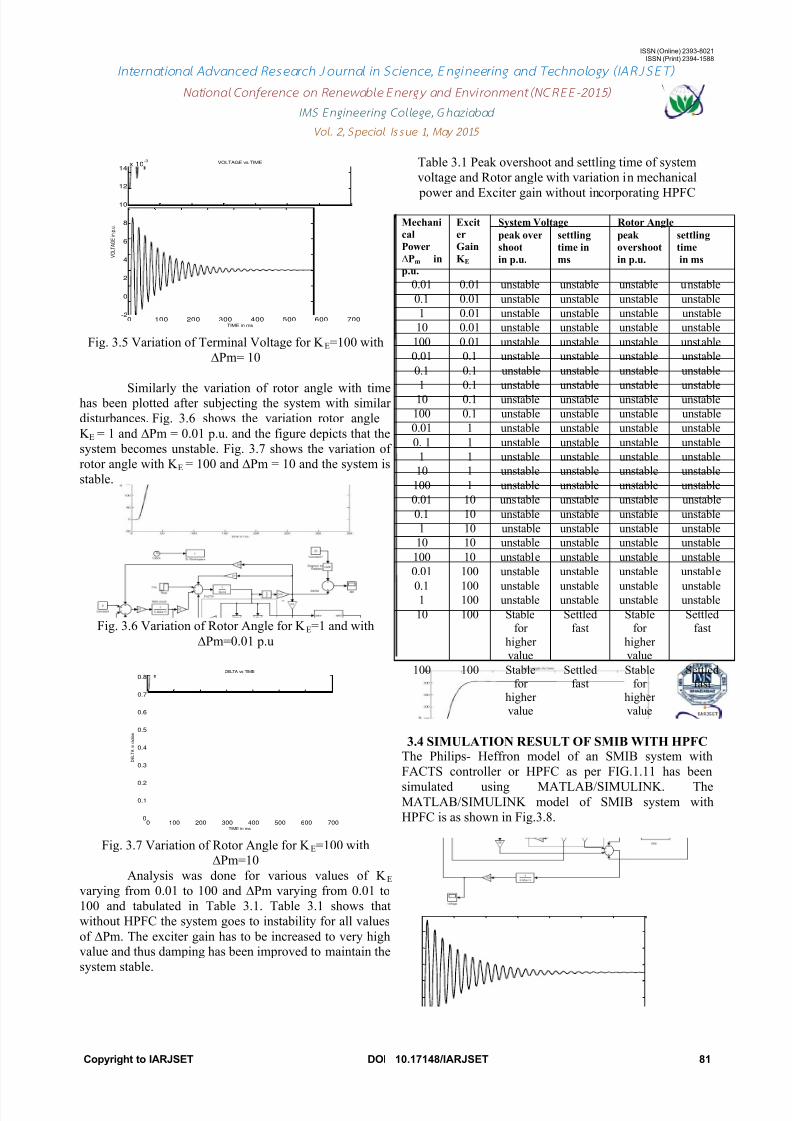
Fig. 3.5 Variation of Terminal Voltage for K E=100 with
∆Pm= 10
Similarly the variation of rotor angle with timehas been plotted after subjecting the system with similar
disturbances. Fig. 3.6 shows the variation rotor angle
K E = 1 and ∆Pm = 0.01 p.u. and the figure depicts that the
system becomes unstable. Fig. 3.7 shows the variation of
rotor angle with K E = 100 and ∆Pm = 10 and the system is
stable.
Fig. 3.6 Variation of Rotor Angle for K E=1 and with
∆Pm=0.01 p.u
Fig. 3.7 Variation of Rotor Angle for K E=100 with∆Pm=10
Analysis was done for various values of K Evarying from 0.01 to 100 and ∆Pm varying from 0.01 to
100 and tabulated in Table 3.1. Table 3.1 shows that
without HPFC the system goes to instability for all values
of ∆Pm. The exciter gain has to be increased to very highvalue and thus damping has been improved to maintain the
system stable.
Table 3.1 Peak overshoot and settling time of system
voltage and Rotor angle with variation in mechanical
power and Exciter gain without incorporating HPFC
Mechani
cal
Power
∆Pm in
p.u.
Excit
er
Gain
K E
System Voltage Rotor Angle
peak over
shoot
in p.u.
settling
time in
ms
peak
overshoot
in p.u.
settling
time
in ms
0.01 0.01 unstable unstable unstable unstable
0.1 0.01 unstable unstable unstable unstable
1 0.01 unstable unstable unstable unstable
10 0.01 unstable unstable unstable unstable
100 0.01 unstable unstable unstable unstable
0.01 0.1 unstable unstable unstable unstable
0.1 0.1 unstable unstable unstable unstable
1 0.1 unstable unstable unstable unstable
10 0.1 unstable unstable unstable unstable
100 0.1 unstable unstable unstable unstable
0.01 1 unstable unstable unstable unstable
0. 1 1 unstable unstable unstable unstable
1 1 unstable unstable unstable unstable
10 1 unstable unstable unstable unstable
100 1 unstable unstable unstable unstable
0.01 10 unstable unstable unstable unstable
0.1 10 unstable unstable unstable unstable
1 10 unstable unstable unstable unstable
10 10 unstable unstable unstable unstable
100 10 unstable unstable unstable unstable
0.01 100 unstable unstable unstable unstable
0.1 100 unstable unstable unstable unstable1 100 unstable unstable unstable unstable
10 100 Stablefor
highervalue
Settledfast
Stablefor
highervalue
Settledfast
100 100 Stablefor
highervalue
Settledfast
Stablefor
highervalue
Settledfast
3.4 SIMULATION RESULT OF SMIB WITH HPFCThe Philips- Heffron model of an SMIB system with
FACTS controller or HPFC as per FIG.1.11 has been
simulated using MATLAB/SIMULINK. TheMATLAB/SIMULINK model of SMIB system with
HPFC is as shown in Fig.3.8.
0 100 200 300 400 500 600 700-2
0
2
4
6
8
10
12
14x 10
-3
TIME in ms
V O L T A G E
i n p . u .
VOLTAGE vs TIME
0 100 200 300 400 500 600 7000
0.1
0.2
0.3
0.4
0.5
0.6
0.7
0.8
TIME in ms
D E L T A i n
r a d i a n
DELTA vs TIME

7/25/2019 pv555
http://slidepdf.com/reader/full/pv555 6/8
ISSN (Online) 2393-8021ISSN (Print) 2394-1588
International Advanced Research Jo urnal in Science, Engineering and Techno logy (IARJSET)
National Conferen ce on Renewable Energy and Enviro nm ent (NCREE-2015)
IMS Engineering College, Ghaziabad
Vol. 2, Special Issue 1, May 2015
Copyright to IARJSET DOI 10.17148/IARJSET 82
Fig. 3.8 Simulation Model for SMIB with Hybrid Power
Flow Controller
The model in Fig.3.8 has been analyzed for stabilitystudies by subjecting to small disturbance by varying the
mechanical power ∆Pm and exciter gain K E.
Fig. 3.9 Variation of Terminal Voltage for K E=1 with
∆Pm= 100 K HPFC = 1
Fig.3.9 shows variation of terminal voltage when
subjected to small disturbance of mechanical power(∆Pm)
= 0.01 p.u. with Exciter gain (K E) =1 and Hybrid Power
Flow Controller (HPFC) is functioning and system
become unstable. The system behavior in respect tosystem voltage is again obtained by increasing the value of
∆Pm = 100 and K E = 1 and found to be stable as shown in
Fig. 3.10
Fig. 3.10 Variation of Terminal Voltage for K E=1 with∆Pm= 100 K HPFC = 10
Similarily the variation of rotor angle with time has been
plotted after subjecting the system with similar
disturbances. Fig. 3.11 shows the variation rotor angle K E= 1 and ∆Pm = 100 and the figure depicts that the system
becomes unstable. Fig. 3.12 shows the variation of rotorangle with K E = 1 and ∆Pm = 100 and the system is stable.
Fig. 3.11 Variation of Rotor Angle for K E=1 with∆Pm=100 K HPFC = 1
Fig. 3.12 Variation of Rotor Angle for K E=1 and KHPFC
=10 with ∆Pm= 100
Analysis was done for various values of K E varying from
0.01 to 100 and ∆Pm varying from 0.01 to 100 and
tabulated in Table 3.2. Table 3.2 shows that with HPFC
the system goes to instability for all values of ∆Pm. The
exciter gain has to be same and increasing the value of
HPFC gain thus damping has been improved to maintain
the system stable.
Table 3.2 Peak overshoot and settling time of system
voltage and Rotor angle with variation in mechanical
power and Exciter gain incorporating HPFC
3.5 TRANSIENT STABILITY ANALYSIS
Mech
anical
Powe
r
∆Pm
in p.u.
Exci
ter
Gai
n
K E
System Voltage Rotor Angle
peak
overshoot
in p.u.
settling
time in
ms
peak
overshoot
in p.u.
settling
time
in ms
0.01 0.01
unstable unstable unstable unstable
0.1 0.0
1
unstable unstable unstable unstable
1 0.0
1
unstable unstable unstable unstable
10 0.01
unstable unstable unstable unstable
100 0.01
unstable unstable unstable unstable
0.01 0.1 unstable unstable unstable unstable
0.1 0.1 unstable unstable unstable unstable
1 0.1 unstable unstable unstable unstable
10 0.1 unstable unstable unstable unstable
100 0.1 unstable unstable unstable unstable
0.01 1 stable stable stable stable
0.1 1 stable stable stable stable
1 1 stable stable stable stable
10 1 stable stable stable stable
100 1 stable stable stable stable
0.01 10 stable stable stable stable
0.1 10 stable stable stable stable
1 10 stable stable stable stable
10 10 stable stable stable stable
100 10 stable stable stable stable
0.01 100 stable stable stable stable
0.1 100 stable stable stable stable
1 100 stable stable stable stable
10 100 stable stable stable stable
100 100 stable stable stable stable
7/25/2019 pv555
http://slidepdf.com/reader/full/pv555 7/8
ISSN (Online) 2393-8021ISSN (Print) 2394-1588
International Advanced Research Jo urnal in Science, Engineering and Techno logy (IARJSET)
National Conferen ce on Renewable Energy and Enviro nm ent (NCREE-2015)
IMS Engineering College, Ghaziabad
Vol. 2, Special Issue 1, May 2015
Copyright to IARJSET DOI 10.17148/IARJSET 83
When a three phase short circuit fault occurs on power
system, the machine accelerates and the looses its
synchronism. If the fault is cleared at a particular time, thesystem retain its stability. The particular instant at whichthe fault may be cleared so that the system stability is
maintained is known as the critical clearin time and the
corresponding angle is called critical clearing angle. One
of the most important tasks in transient stability
assessment is the determination of the critical clearing
time(CCT). HPFC installed on the system improves the
critical clearing time(CCT) more effectively.
A fault has been incorporated in the system and the rotor
angle variation are observed for different values of fault
clearing time(FCT).
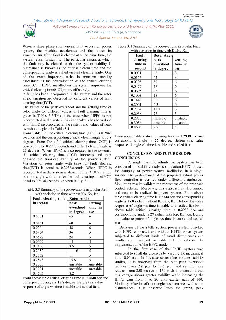
The values of the peak overshoot and the settling time of
rotor angle for different values of fault clearing time isgiven in Table. 3.3.This is the case when HPFC is not
incorporated in the system. Similar analysis has been done
with HPFC incorporated in the system and values of peak
overshoot is given in Table.3.4.
From Table 3.3. the critical clearing time (CCT) is 0.2848seconds and the corresponding critical clearin angle is 15.8
degrees. From Table 3.4 critical clearing time (CCT) is
observed to be 0.2938 seconds and critical clearin angle is
27 degrees. When HPFC is incorporated in the system ,
the critical clearing time (CCT) improves and then
enhance the transient stability of the power system.
Variation of rotor angle with time for fault clearing
time(FCT) is equal to 0.2938seconds. When HPFC isincorporated in the system is shown in Fig. 3.10 Variation
of rotor angle with time for the fault clearing time(FCT)
equal to 0.3036 seconds is shown in Fig. 3.11.
Table 3.3 Summary of the observations in tabular form
with variation in time without Kp, Kv, Kq
Fault clearing time
in second
Rotor Angle
peak
overshoot
in degree
settling
time in
sec
0.0031 65 6
0.0151 60 60.0304 48 6
0.0474 36 5
0.0692 24 5
0.0999 15 5
0.1436 8.5 5
0.2052 6 5
0.2752 11 5
0.2848 15.8 5
0.3075 unstable unstable
0.3721 unstable unstable
0.4603 8.2 5
From above table critical clearing time is 0.2848 sec and
corresponding angle is 15.8 degree. Before this value
response of angle v/s time is stable and settled fast.
Table 3.4 Summary of the observations in tabular form
with variation in time with K P,K V,Kq
Faultclearing
time in
second
Rotor Anglepeak
overshoot
in degree
settling
time in
sec
0.0031 68 8
0.0153 62 8
0.0305 50 6
0.0475 37 6
0.0695 25 6
0.1003 15 6
0.1442 8.5 6
0.2061 6.3 6
0.2762 11.7 6
0.2938 27 5
0.2958 unstable unstable
0.3036 unstable unstable
0.4605 9.2 5
From above table critical clearing time is 0.2938 sec and
corresponding angle is 27 degree. Before this value
response of angle v/s time is stable and settled fast.
CONCLUSION AND FUTURE SCOPE
CONCLUSION A single machine infinite bus system has been
considered for stability analysis simulation.HPFC is usedfor damping of power system oscillation in a single
system. The performance of the proposed hybrid power
flow controller is verified under different disturbances.Simulation results validate the robustness of the proposed
control scheme. Moreover, this approach is also simple
and easy to be realized in power systems. From above
table critical clearing time is 0.2848 sec and corresponding
angle is 15.8 radian without Kp, Kv, Kq. Before this value
response of angle v/s time is stable and settled fast.From
above table critical clearing time is 0.2938 sec and
corresponding angle is 27 radian with Kp, Kv, Kq. Before
this value response of angle v/s time is stable and settled
fast.Behavior of the SMIB system power system checkedwith HPFC connected and without HPFC, when system
subjected to different kinds of small disturbances and
results are presented in table 3.1 to validate the
implementation of the HPFC model.
In the first case of the SMIB system was
subjected to small disturbances by varying the mechanicalinput 0.01 p.u. In this case system bus voltage stability
studies, it is observed from the plot peak overshoot
reduces from 2.9 p.u. to 1.45 p.u., and settling time
reduces from 250 ms sec to 160 ms.It is understood that
bus voltage shows greater stability while increasing the
HPFC gain from 1 to 20 with exciter gain of 100.Similarly behavior of rotor angle has been seen with same
disturbances. It is observed from the graph, peak

7/25/2019 pv555
http://slidepdf.com/reader/full/pv555 8/8
ISSN (Online) 2393-8021ISSN (Print) 2394-1588
International Advanced Research Jo urnal in Science, Engineering and Techno logy (IARJSET)
National Conferen ce on Renewable Energy and Enviro nm ent (NCREE-2015)
IMS Engineering College, Ghaziabad
Vol. 2, Special Issue 1, May 2015
Copyright to IARJSET DOI 10.17148/IARJSET 84
overshoot reduces from 7.8p.u. to 6.52 p.u. and settling
time reduces from 190ms to 130ms sec.
From the above results it is concluded that theaction of HPFC definitely improves the system stabilityand damps the power system oscillations if HPFC
parameters are selected carefully. Hence the stability of
the system has been enhanced with the effective control of
hybrid power flow controller.
This study shows the role of receding horizon
principle based hybrid power flow controller in improving
the transient stability of a very complex hybrid system
with high nonlinearities and constraints. As the complete
detailed dynamic machine model is considered, variation
in all parameters can be observed and stability can be
enhanced. Thus increasing demand and restriction on
having additional new infrastructure, forces the existing power system network to work at its maximum possible
limits.
This study presents a useful insight for power
utility engineers to evaluate the application of HPFC and
its impact on power system. HPFC is an advancedconfiguration that controls the operation of active and
reactive power flow. HPFC will significantly extend the
active power and reactive power flow capability and offer
a great potential in solving many of the problems faced by
the electric utility in a competitive environment. The
simulation results prove the capability and performance of
HPFC in dynamic control of power flow if A dynamic
control strategy is developed in the boundaries ofcontrollable range of HPFC to enhance the dynamic
voltage stability.
4.2 FUTURE SCOPE OF THE THESIS
This model can also be used for Power System
Analysis Software Package (PSASP). It can also be used
with Power System Stabilizer (PSS). It can be used as
MATLAB/SIMULINK hard-ware model. Further it can be
extended with ANFIS. This can be further extended for
GA and PSO to improve power system stability.
REFERENCES
1. Kundur, P.; Paserba, J.; Ajjarapu, V.; Andersson, G.; Bose, A.;Canizares, C.; Hatziargyriou, N.; Hill, D.; Stankovic, A.; Taylor,
C.; Van Cutsem, T.; Vittal, V.; "Definition and Classification of
Power System Stability", IEEE Transactions on Power Systems
Vol. 19 , pp 1387 – 1401 , 2004.2. Shahgholian, G.; Shafaghi, P.; Moalem, S.; Mahdavian, M.;
"Damping Power System Oscillations in Single-Machine Infinite-
Bus Power System Using a STATCOM" International Conferenceon Computer and Electrical Engineering, ICCEE. Vol1, pp130 –
134 , 2009.
3. Gurrala, G.; Sen, I.; "A Modified Heffron-Phillip's Model for theDesign of Power System Stabilizers" Joint International Conference
on Power System Technology and IEEE Power India Conference,
POWERCON , pp 1 – 6, 2008.4. Zarringhalami, M.; Hakimi, S.M.; Javadi, M.; "Optimal Regulation
of STATCOM Controllers and PSS Parameters using Hybrid
Particle Swarm Optimization" 14
th
International ConferenceonHarmonics and Quality of Power (ICHQP), pp 1 – 7, 2010.
5. Praing, Ch.; Tran-Quoc, T.; Feuillet, R.; Sabonnadiere, J.C.;
Nicolas, J.; Nguyen-Boi, K.; Nguyen-Van, L.; "Impact of FACTSDevices On Voltage And Transient Stability of a Power System
Including Long Transmission Lines"IEEE Transaction on Power
Engineering Society. Vol. 3 , pp1906 - 1911 , 2000.6. Khuntia, S.R.; Panda, S.; "ANFIS Approach for TCSC-based
Controller Design for Power System Stability Improvement"IEEEInternational Conference on Communication Control andComputing Technologies (ICCCCT),
pp 149 – 154 , 2010.
7. Swaroopan, N.M. , Somasundaram, P.; "Transient Stability
Enhancement with UPFC" International Conference on Information
and Communication Technology in Electrical Sciences ICTES,
pp510 - 516 , 2007.8. Behar, B. Lamnabhi-Lagarrigue, F. Ahmed-Ali, T.;
"Robust Nonlinear Control of Transient Stability of Power
Systems" IEEE Conference on Decision and Control, Vol. 1 pp294- 299 , 2003.
9. Wagh, R; Kamath, A. K.; Singh, N.M.; "Non-linear Model
Predictive Control for Improving Transient Stability of PowerSystem using TCSC Controller" Asian Control Conference, ASCC
pp1627-1632 , 2009.
10. WuZhongxi;ZhouXiaoxin"Power System Analysis Software Package (PSASP)- an
Integrated Power System Analysis Tool International Conference
on Integrated Power System Analysis Technology, Vol-1, pp 7-11,1998.
11. Abdul-Malek, M.A.; Abido, M.A.; "STATCOM based Controller
Design using Particle Swarm Optimization for Power SystemStability Enhancement" IEEE Transaction on International
Symposium Industrial Electronics, ISIE , pp 1218 – 1223, 2009 .
12. Suresh, Y.; Panda, A.K.; "Dynamic Performance of STATCOMUnder Line to Ground Faults in Power SystemPower Electronics".
International Conference on Machines and Drives (PEMD 2010),
pp1 - 6 , 2010.13. Lerch, E.N.; Povh, D.; Xu, L.; "Advanced SVC Control for
Damping Power System Oscillations" IEEE Transactions on Power
Systems, Vol.6 ,No. 2 pp 524 – 535 , 1991.
14. Poshtan, M.; Singh, B.N.; Rastgoufard, P.; "A NonlinearControl Method for SSSC to Improve Power System
Stability."International Conference on Power Electronics, Drivesand Energy Systems, PEDES , pp 1 – 7, 2006.
15. Zhang, X.C.; Cheng, G.H.; Xu, Z.; "User Defined Excitation
System Models for Power System Stability Analysis"Transmissionand Distribution Conference and Exhibition: Asia and Pacific, in
PSASPpp 1 - 5 , 2005.
16. Rai, D.; Faried, S.O.; Ramakrishna, G.; Edris, A.; "Hybrid SeriesCompensation Scheme Capable of Damping Subsynchronous
Resonance" IET Proceeding on Generation, Transmission &
Distribution, Vol. 4 , No. 3 pp 456 - 466, 2010.17. Senjyu,T.;Yamane,S.;Uezato,K.; "Enhancement of Power System
Stability with FACTS using Adaptive Fuzzy ControllerSystems",
IEEE International Conference on Man, and Cybernetics, Vol. 6,pp533 – 538 , 1999 .
18. Alam, A.; Abido, M.A.; "Parameter Optimization of Shunt FACTSControllers for Power System Transient Stability Improvement"
IEEE Power Tech conference, pp 2012 – 2017,2007.
19. Chandrakar, V.K.; Dhurvey, S.N.; Suke, S.C.; "PerformanceComparison of SVC with POD and PSS for Damping of Power
System Oscillations"International Conference on Emerging Trends
in Engineering and Technology (ICETET), pp247 - 252 , 2010 .20. Bebic, J.Z.; Lehn, P.W.; Iravani, M.R.; "The Hybrid Power Flow
Controller - A New Concept for Flexible AC Transmission"IEEE
Power Engineering Society General Meeting, 2006.