technical report - 株式会社qt inter-cell interference coordination ... this technical report has...
TRANSCRIPT

3GPP TR 36.902 V9.1.0 (2010-03) Technical Report
3rd Generation Partnership Project;Technical Specification Group Radio Access Network;Evolved Universal Terrestrial Radio Access Network
(E-UTRAN); Self-configuring and self-optimizing network (SON) use cases
and solutions(Release 9)
The present document has been developed within the 3rd Generation Partnership Project (3GPP TM) and may be further elaborated for the purposes of 3GPP. The present document has not been subject to any approval process by the 3GPP Organizational Partners and shall not be implemented. This Specification is provided for future development work within 3GPP only. The Organizational Partners accept no liability for any use of this Specification. Specifications and reports for implementation of the 3GPP TM system should be obtained via the 3GPP Organizational Partners' Publications Offices.
2 3GPP TR 36.902 V9.1.0 (2010-03)Release 9
UMTS™ is a Trade Mark of ETSI registered for the benefit of its members
3GPP™ is a Trade Mark of ETSI registered for the benefit of its Members and of the 3GPP Organizational Partners LTE™ is a Trade Mark of ETSI currently being registered for the benefit of its Members and of the 3GPP Organizational Partners GSM® and the GSM logo are registered and owned by the GSM Association
Keywords LTE, radio
3GPP
Postal address
3GPP support office address 650 Route des Lucioles - Sophia Antipolis
Valbonne - FRANCE Tel.: +33 4 92 94 42 00 Fax: +33 4 93 65 47 16
Internet http://www.3gpp.org
Copyright Notification
No part may be reproduced except as authorized by written permission. The copyright and the foregoing restriction extend to reproduction in all media.
© 2010, 3GPP Organizational Partners (ARIB, ATIS, CCSA, ETSI, TTA, TTC).
All rights reserved.
3 3GPP TR 36.902 V9.1.0 (2010-03)Release 9
Contents Foreword ...................................................................................................................................................... 5 Introduction .................................................................................................................................................. 5 1 Scope .................................................................................................................................................. 6 2 References .......................................................................................................................................... 6 3 Definitions, symbols and abbreviations ............................................................................................... 6 3.1 Definitions ................................................................................................................................................... 6 3.2 Symbols ....................................................................................................................................................... 6 3.3 Abbreviations............................................................................................................................................... 7 4 Description of envisioned self configuring and self optimizing functionality, Use cases ....................... 7 4.1 Coverage and capacity optimization ............................................................................................................. 7 4.1.1 Use Case description ............................................................................................................................... 7 4.1.2 Required functionality ............................................................................................................................ 7 4.1.3 Evaluation scenarios and expected results................................................................................................ 8 4.1.4 O&M requirements for radio related functions ........................................................................................ 8 4.1.5 Solution Description ............................................................................................................................... 8 4.1.5.1 Input data, definition of Measurements or Performance data ............................................................... 8 4.1.5.2 Output, influenced entities and parameter .......................................................................................... 8 4.1.5.3 Impacted specifications, procedure interactions and interfaces ............................................................ 8 4.2 Energy Savings ............................................................................................................................................ 8 4.2.1 Use Case description ............................................................................................................................... 8 4.2.2 Solution Description ............................................................................................................................... 9 4.2.2.1 Input data, definition of Measurements or Performance data ............................................................... 9 4.2.2.2 Output, influenced entities and parameter .......................................................................................... 9 4.2.2.3 Impacted specifications, procedure interactions and interfaces ............................................................ 9 4.3 Interference Reduction ................................................................................................................................. 9 4.3.1 Use Case description ............................................................................................................................... 9 4.3.2 Solution Description ............................................................................................................................... 9 4.3.2.1 Input data, definition of Measurements or Performance data ............................................................... 9 4.3.2.2 Output, influenced entities and parameter .......................................................................................... 9 4.3.2.3 Impacted specifications, procedure interactions and interfaces ............................................................ 9 4.4 Automated Configuration of Physical Cell Identity ....................................................................................... 9 4.4.1 Use Case description ............................................................................................................................... 9 4.4.2 Solution Description ............................................................................................................................. 10 4.4.2.1 Input data, definition of Measurements or Performance data ........................................................... 10 4.4.2.2 Output, influenced entities and parameter ........................................................................................ 10 4.4.2.3 Impacted specifications and interfaces ............................................................................................ 11 4.5. Mobility robustness optimisation ................................................................................................................ 11 4.5.1 Use Case description ............................................................................................................................. 11 4.5.2 Required Functionality .......................................................................................................................... 11 4.5.2.1 Detection of Too Late HO ............................................................................................................... 11 4.5.2.2 Detection of Too Early HO .............................................................................................................. 11 4.5.2.3 Detection of HO to a Wrong Cell ..................................................................................................... 11 4.5.2.4 Reducing inefficient use of network resources due to unnecessary HOs ............................................ 12 4.5.2.5 Optimization of cell reselection parameters ...................................................................................... 12 4.5.3 Evaluation scenarios and expected results.............................................................................................. 12 4.5.4 O&M requirements for radio related functions ...................................................................................... 12 4.5.5 Solution Description ............................................................................................................................. 12 4.5.5.1 Input data, definition of Measurements or Performance data ............................................................. 12 4.5.5.1.1 Detection of Too Late HOs ........................................................................................................ 13 4.5.5.1.2 Detection of Too Early HO ........................................................................................................ 13 4.5.5.2 Output, influenced entities and parameter ........................................................................................ 13 4.5.5.3 Impacted specifications and interfaces ............................................................................................. 13 4.6 Mobility Load balancing optimisation ........................................................................................................ 13 4.6.1 Use Case description ............................................................................................................................. 13
4 3GPP TR 36.902 V9.1.0 (2010-03)Release 9
4.6.2 Required functionality .......................................................................................................................... 16 4.6.3 Evaluation criteria and expected results ................................................................................................. 16 4.6.4 O&M requirements for radio related functions ...................................................................................... 16 4.6.5 Solution description for Intra LTE load balancing .................................................................................. 17 4.6.5.1 Input data, definition of Measurements or Performance data ............................................................. 17 4.6.5.2 Output, influenced entities and parameter ........................................................................................ 17 4.6.5.3 Impacted specifications and interfaces ............................................................................................. 17 4.6.6 Solution description for Inter RAT load balancing ................................................................................. 17 4.6.6.1 Input data, definition of Measurements or Performance data ............................................................. 18 4.6.6.2 Output, influenced entities and parameter ........................................................................................ 18 4.6.6.3 Impacted specifications and interfaces ............................................................................................. 18 4.7 RACH Optimisation ................................................................................................................................... 18 4.7.1 Use Case description ............................................................................................................................. 18 4.7.2 Objective .............................................................................................................................................. 19 4.7.3 Expected results .................................................................................................................................... 19 4.7.4 Solution Description ............................................................................................................................. 20 4.7.4.1 Performance data, Input data and definition of Measurements .......................................................... 20 4.7.4.1.1 Performance Specification .......................................................................................................... 20 4.7.4.1.2 Input Data .................................................................................................................................. 20 4.7.4.1.3 Definition of Measurements ....................................................................................................... 21 4.7.4.2 Output, influenced entities and parameters ....................................................................................... 22 4.7.4.3 Impacted specifications, procedure interactions and interfaces .......................................................... 22 4.7.4.3.1 Stage 2 and stage 3 specifications .................................................................................................... 22 4.7.4.3.1.1 Stage 2 specification .................................................................................................................. 22 4.7.4.3.1.2 Stage 3 specification .................................................................................................................. 22 4.7.5 O&M requirements ............................................................................................................................... 22 4.8 Automatic Neighbour Relation Function ..................................................................................................... 23 4.9 Inter-cell Interference Coordination ............................................................................................................ 23 4.9.1 Use Case description ............................................................................................................................. 23 4.9.2 Solution Description for self-configuration of UL/DL Interference Coordination ................................... 24 4.9.2.1 Input data, definition of Measurements or Performance data ............................................................. 24 4.9.2.2 Output, influenced entities and parameter ........................................................................................ 24 4.9.2.3 Impacted specifications, procedure interactions and interfaces .......................................................... 24 4.9.3 Solution Description for self-optimisation of UL/DL Interference Coordination ..................................... 24 4.9.3.1 Input data, definition of Measurements or Performance data ............................................................. 24 4.9.3.2 Output, influenced entities and parameter ........................................................................................ 24 4.9.3.3 Impacted specifications and interfaces ............................................................................................. 24 Annex A: Change history ............................................................................................................................ 25
5 3GPP TR 36.902 V9.1.0 (2010-03)Release 9
Foreword This Technical Report has been produced by the 3rd Generation Partnership Project (3GPP).
The contents of the present document are subject to continuing work within the TSG and may change following formal TSG approval. Should the TSG modify the contents of the present document, it will be re-released by the TSG with an identifying change of release date and an increase in version number as follows:
Version x.y.z
where:
x the first digit:
1 presented to TSG for information;
2 presented to TSG for approval;
3 or greater indicates TSG approved document under change control.
y the second digit is incremented for all changes of substance, i.e. technical enhancements, corrections, updates, etc.
z the third digit is incremented when editorial only changes have been incorporated in the document.
Introduction Reduction of operational efforts and complexity are key drivers for RAN Long Term Evolution. One of the important aspects to this is that the system operability is improved under multi vendor environment. It is of importance that measurements and performance data of different vendors share the same “language.” Such alignment is easing ease network performance analyses and problem finding, and reduces efforts in maintaining the network at a properly working state.
It is also of interest to minimise operational effort by introducing self configuring and self optimising mechanisms. A self optimising function shall increase network performance and quality reacting to dynamic processes in the network.
Especially in the early deployment phase, the efforts to set up and optimise are significant and traditionally lead to lengthy periods of getting an optimum and stable system setup. It is thus essential to have the necessary set of self configuration and self optimisation mechanisms already available when initial deployment starts.
As such, standardisation is asked to define the necessary measurements, procedures and open interfaces to support better operability under multi vendor environment. Such standardised functions shall also facilitate self configuration and self optimisation under multi vendor environment. Especially the interaction between self configuring/optimizing networks and O&M has to be considered.

6 3GPP TR 36.902 V9.1.0 (2010-03)Release 9
1 Scope The present document provides descriptions of agreed use cases and solutions with regards to self configuring and self optimizing networks.
The scope of the self configuring and self optimizing functionality is defined in [2].
2 References The following documents contain provisions which, through reference in this text, constitute provisions of the present document.
References are either specific (identified by date of publication, edition number, version number, etc.) or non-specific.
For a specific reference, subsequent revisions do not apply.
For a non-specific reference, the latest version applies. In the case of a reference to a 3GPP document (including a GSM document), a non-specific reference implicitly refers to the latest version of that document in the same Release as the present document.
[1] 3GPP TR 21.905: "Vocabulary for 3GPP Specifications".
[2] 3GPP TS 36.300: "Radio Access (E-UTRAN); Overall description; Stage 2".
[3] 3GPP TS 36.211: "Radio Access (E-UTRA); Physical Channels and Modulation"
[4] 3GPP TS 36.304: "Evolved Universal Terrestrial Radio Access (E-UTRA); User Equipment (UE) procedures in idle mode".
[5] 3GPP TS 36.331: "Evolved Universal Terrestrial Radio Access (E-UTRA); Radio Resource Control (RRC); Protocol specification".
[6] 3GPP TS 36.321: "Radio Access (E-UTRA); Medium Access Control (MAC) Protocol Specification".
[7] 3GPP TS 36.423: "X2 application protocol (X2AP) "
3 Definitions, symbols and abbreviations
3.1 Definitions For the purposes of the present document, the terms and definitions given in TR 21.905 [1] and the following apply. A term defined in the present document takes precedence over the definition of the same term, if any, in TR 21.905 [1].
3.2 Symbols For the purposes of the present document, the following symbols apply:
<symbol> <Explanation>
7 3GPP TR 36.902 V9.1.0 (2010-03)Release 9
3.3 Abbreviations For the purposes of the present document, the abbreviations given in TR 21.905 [1] and the following apply. An abbreviation defined in the present document takes precedence over the definition of the same abbreviation, if any, in TR 21.905 [1].
DRX Discontinuous Reception ICIC Inter-cell Interference Coordination OFDM Orthogonal Frequency Division Multiplexing PRB Physical Resource Block RACH Random Access CHannel RAT Radio Access Technology RRM Radio Resource Management SC-FDMA Single Carrier Frequency Division Multiple Access
4 Description of envisioned self configuring and self optimizing functionality, Use cases
4.1 Coverage and capacity optimization A typical operational task is to optimize the network according to coverage and capacity. Planning tools support this task based on theoretical models but for both problems measurements must be derived in the network. Call drop rates give a first indication for areas with insufficient coverage, traffic counters identify capacity problems.
4.1.1 Use Case description The use case will have two main objectives:
Providing optimal coverage
This objective requires that in the area, where LTE system is offered, users can establish and maintain connections with acceptable or default service quality, according to operator’s requirements. It implies therefore that the coverage is continuous and users are unaware of cell borders. The coverage must be therefore provided in both, idle and active mode for both, UL and DL.
Providing optimal capacity
While coverage optimization has higher priority than capacity optimization in Rel-9, the coverage optimization algorithms must take the impact on capacity into account. Since coverage and capacity are linked, a trade-off between the two of them may also be a subject of optimisation.
4.1.2 Required functionality To achieve the above objectives, following functionalities have to be implemented:
Detection of unintended holes in the coverage (planned by the operator and technically feasible)
Coverage optimisation, including:
o DL channel coverage
o UL channel coverage
8 3GPP TR 36.902 V9.1.0 (2010-03)Release 9
o DL and UL channel coverage match
Ability to balance the trade-off between coverage and capacity
Reference signal pollution optimisation
4.1.3 Evaluation scenarios and expected results The selected solution, besides fulfilling the requirements, is likely to result in:
Continuous, optimized and matched UL and DL coverage
Optimised DL and UL capacity of the system
Balanced tradeoff between coverage and capacity
Interference reduction
Controlled cell edge performance
Minimized human intervention in network management and optimization tasks
Energy savings
4.1.4 O&M requirements for radio related functions
4.1.5 Solution Description
4.1.5.1 Input data, definition of Measurements or Performance data
4.1.5.2 Output, influenced entities and parameter
4.1.5.3 Impacted specifications, procedure interactions and interfaces
4.2 Energy Savings A typical critical cost for the operator is the energy expenses. Cuts on energy expenses could be realized if the capacity offered by the network would match the needed traffic demand at any point of time as close as possible.
4.2.1 Use Case description Objective:
Energy savings based on e.g. cell switch on/off.
Expected outcome:
Cuts on operational expenses through energy savings.
9 3GPP TR 36.902 V9.1.0 (2010-03)Release 9
4.2.2 Solution Description
4.2.2.1 Input data, definition of Measurements or Performance data
4.2.2.2 Output, influenced entities and parameter
4.2.2.3 Impacted specifications, procedure interactions and interfaces
4.3 Interference Reduction Capacity could be improved through interference reduction by switching off those cells which are not needed for traffic at some point of time, in particular home eNodeBs when the user is not at home.
4.3.1 Use Case description Objective:
Interference reduction based on cell switch on/off.
Expected outcome:
Increased capacity through interference reduction.
Increased quality through interference reduction.
4.3.2 Solution Description
4.3.2.1 Input data, definition of Measurements or Performance data
4.3.2.2 Output, influenced entities and parameter
4.3.2.3 Impacted specifications, procedure interactions and interfaces
4.4 Automated Configuration of Physical Cell Identity
4.4.1 Use Case description Objective:
Automatic configuration of the Physical ID of an eNB’s radio cell
The proposed SON use case provides an automated configuration of a newly introduced cell’s physical ID (L1 cell identifier [2]).

10 3GPP TR 36.902 V9.1.0 (2010-03)Release 9
Figure 4.4.1: Deployment Illustration
The physical cell identity, or L1 identity (Phy_ID in this document), is an essential configuration parameter of a radio cell, it corresponds to a unique combination of one orthogonal sequence and one pseudo-random sequence, and 504 unique Phy_IDs are supported –leading to unavoidable reuse of the Phy_ID in different cells [3].
When a new eNodeB is brought into the field, a Phy_ID needs to be selected for each of its supported cells, avoiding collision with respective neighbouring cells (the use of identical Phy_ID by two cells results in interference conditions hindering the identification and use of any of them where otherwise both would have coverage). Traditionally, the proper Phy_ID is derived from radio network planning and is part of the initial configuration of the node. The Phy_ID assignment shall fulfil following conditions,
“collision-free”: the Phy_ID is unique in the area that the cell covers
“confusion-free”: a cell shall not have neighbouring cells with identical Phy_ID
4.4.2 Solution Description Self-configuration case applied during initial cell configuration
Functionality: selection of a Physical ID for a newly deployed radio cell
Actions:
FFS
Expected outcome:
Selection of Phy_ID without conflicts.
4.4.2.1 Input data, definition of Measurements or Performance data
(FFS)
4.4.2.2 Output, influenced entities and parameter
Output parameters from the SON function are:
Self-configuration of Phy_ID
11 3GPP TR 36.902 V9.1.0 (2010-03)Release 9
4.4.2.3 Impacted specifications and interfaces
There may be an impact related to the method to be used for obtaining existing configuration at neighbours that is FFS.
4.5. Mobility robustness optimisation
4.5.1 Use Case description Manual setting of HO parameters in current 2G/3G systems is a time consuming task. In many cases, it is considered too costly to update the mobility parameters after the initial deployment.
For some cases, RRM in one eNB can detect problems and adjust the mobility parameters, but there are also examples where RRM in one eNB can not resolve problems:
Incorrect HO parameter settings can negatively affect user experience and wasted network resources by causing HO ping-pongs, HO failures and radio link failures (RLF). While HO failures that do not lead to RLFs are often recoverable and invisible to the user, RLFs caused by incorrect HO parameter settings have a combined impact on user experience and network resources. Therefore, the main objective of mobility robustness optimization should be reducing the number of HO-related radio link failures. Furthermore, non-optimal configuration of handover parameters, even if it does not result in RLFs, may lead to serious degradation of the service performance. Example of such a situation is incorrect setting of the HO hysteresis, which may be the reason for either ping-pong effect or prolonged connection to non-optimal cell. Thus the secondary objective will be reduction of the inefficient use of network resources due to unecessary or missed handovers.
HO-related failures can be categorized as follows:
Failures due to too late HO triggering
Failures due to too early HO triggering
Failures due to HO to a wrong cell
Additionally cell-reselection parameters not aligned with HO parameters may result in unwanted handovers subsequent to connection setup, which should be avoided by parameter adjustments done by MRO function.
4.5.2 Required Functionality
4.5.2.1 Detection of Too Late HO
If the UE mobility is more aggressive than what the HO parameter settings allow for, handover can be triggered when the signal strength of the source cell is already too low – leading to a RLF; or handover may not be triggered at all if a RLF preempts it. Signature of Too Late HOs may be summarized by:
RLF in the source cell before the HO was initiated or during HO procedure,
UE re-establishes the connection in a cell different than the source cell.
4.5.2.2 Detection of Too Early HO
Too early HO can be triggered when the UE enters unintended island of coverage of another cell contained inside the coverage area of the serving cell. This is a typical scenario for areas where fragmented cell coverage is inherent to the radio propagation environment, such as dense urban areas. Signature of Too Early HO may be summarized by:
RLF occurred short time after the UE successfully connected to the target cell
UE re-establishes the connection in the source cell
4.5.2.3 Detection of HO to a Wrong Cell
If the Cell Individual Offset (CIO) [5] parameters are set incorrectly, the handover, albeit timed correctly, will be directed towards a wrong cell. Signature of HO to a wrong cell may be summarized by:
RLF occurred short time after the UE succesfully connected to the target cell
12 3GPP TR 36.902 V9.1.0 (2010-03)Release 9
UE re-establishes the connection in a cell other than the source cell or the target cell
4.5.2.4 Reducing inefficient use of network resources due to unnecessary HOs
HO procedure is resource-consuming and therefore costly to the network operator. Moreover, its optimal settings depend on momentary radio conditions, which makes it difficult to control manually. Sometimes, the combination of user mobility patterns and cell coverage boundary layout can generate frequent unnecessary HOs that consume NW resources inefficiently. Alternatively, incorrect HO configuration (e.g. too big HO hysteresis) may result in missing handovers that should have been executed. HO parameter optimisation function should aim at detecting such scenarios. These scenarios sometimes can be remedied by HO parameter optimisation.
4.5.2.5 Optimization of cell reselection parameters
If cell reselection parameters are not aligned with handover parameter settings, unwanted handovers subsequent to connection setup may occur and should be avoided.
4.5.3 Evaluation scenarios and expected results Expected results:
Detect and minimize occurences of Too Late HOs
Detect and minimize occurences of Too Early HOs
Detect and minimize occurences of HO to a Wrong Cell
Reduce inefficient use of network resources due to unnecessary HOs, e.g. “ping pong”
Reduce unwanted handovers subsequent to connection setup
4.5.4 O&M requirements for radio related functions While algorithms for mobility robustness optimisation should be located in the eNB SON entities, network operators should have the ability to provide their input reflecting their knowledge about the network and their network management policies,
In order to enable mobility robustness optimization:
The relevant mobility robustness parameters should be autoconfigurable by the eNB SON entities.
OAM should be able to configure a valid range of values for these parameters (list of parameters described in Section 4.5.5),
eNB should pick a value from within this configured range, using proprietery algorithms for HO parameter optimisation.
Furthermore, in order to support the solutions for detection of Too Late and Too Early HO, it is required that parameter Tstore_UE_cntxt shall be configurable by the OAM system.
4.5.5 Solution Description
4.5.5.1 Input data, definition of Measurements or Performance data
It is proposed that certain information may be exchanged between neighboring eNBs, to facilitate optimization of mobility robustness parameters:
Report of RLF failures: This report includes the following information elements:
o Failure Cell ID: PCI of the cell in which the RLF occurred.
o Reestablishment Cell ID: PCI and (optionally) ECGI of the cell where RL re-establishment attempt is made

13 3GPP TR 36.902 V9.1.0 (2010-03)Release 9
o C-RNTI: C-RNTI of the UE in the cell where RLF occurred.
NOTE: Reporting both the PCI and ECGI helps to resolve confusion in the network, in case the RLF was due to PCI confusion in the first place.
4.5.5.1.1 Detection of Too Late HOs
The source cell is not always aware of a too late HO because the RLF can occur before the source cell is able to receive the HO-triggering measurement report message (MRM) from the UE. Therefore, a report of the RLF from the target cell in which the radio link is re-established to the source cell is necessary in order to allow the source cell to properly identify the RLF as related to incorrect HO parameter settings. The RLF report can be formalized as follows:
If the UE re-establishes the radio link at eNB B after a RLF at eNB A then eNB B shall report this RLF event to eNB A.
4.5.5.1.2 Detection of Too Early HO
In the event of a too early handover from cell A to cell B, an RLF event may get reported by cell A to cell B according to the mechanism described in Section 4.5.5.1.1, when the UE returns to cell A after RLF. In this case, the cell B will consider it as an indication of a too late HO. This case needs to be prevented in order to ensure the stability of the MRO function in the network. This following mechanism achieves this goal:
eNB B shall return an indication of a Too Early HO event to eNB A when eNB B receives an RLF report from eNB A and if eNB B has sent the UE Context Release message to eNB A related to the completion of an incoming HO for the same UE within the last Tstore_UE_cntxt seconds.
4.5.5.2 Output, influenced entities and parameter
The following mobility parameters may be optmized:
Hysteresis,
Time to Trigger,
Cell Individual Offset
Cell reselection parameters
The list of parameters to be optmized is FFS, depending on the solution adopted.
The parameters related to cell reselection are defined in [4] and those related to handover in [5].
4.5.5.3 Impacted specifications and interfaces
[7]
4.6 Mobility Load balancing optimisation
4.6.1 Use Case description Objective:
Optimisation of cell reselection/handover parameters in order to cope with the unequal traffic load and to minimize the number of handovers and redirections needed to achieve the load balancing.
Self-optimisation of the intra-LTE and inter-RAT mobility parameters to the current load in the cell and in the adjacent cells can improve the system capacity compared to static/non-optimised cell reselection/handover parameters. Such optimisation can also minimize human intervention in the network management and optimization tasks.
The load balancing shall not affect the user QoS negatively beyond what a user would experience at normal mobility without load-balancing. Service capabilities of RATs must be taken into account, and solutions should take into account
14 3GPP TR 36.902 V9.1.0 (2010-03)Release 9
network deployments with overlay of high-capacity and low-capacity layers where high-capacity layer can have spotty coverage.
Load balancing can be done in following scenarios:
Intra-LTE load balancing
Inter-RAT load balancing
4.6.2 Required functionality General features of the solution are as follows:
Functionality: An algorithm decides to distribute the UEs camping on or having a connection to a cell, in order to balance the traffic load. This may be achieved by delaying or advancing the handing over of the UEs between cells.
Actions:
An eNB monitors the load in the controlled cell and exchanges related information over X2 or S1 with neighbouring node(s).
An algorithm identifies the need to distribute the load of the cell towards either adjacent or co-located cells, including cells from other RATs, e.g. by comparing the load among the cells, the type of ongoing services, the cell configuration, etc.
For the intra-LTE case, an algorithm estimates if the HO parameter settings need to be modified; if so, communication between involved eNBs (or towards O&M) takes place to propose changes of the neighbours HO trigger settings to the neighbour eNB.
4.6.3 Evaluation criteria and expected results Expected results:
According to handover mechanisms, some of the UEs at the cell border hand over to a less loaded cell;
In the new situation the cell load is balanced.
Increased capacity of the system.
Minimized human intervention in network management and optimization tasks.
4.6.4 O&M requirements for radio related functions (editor’s note: in this section requirements on O&M respectively paramenters to be made configurable in a
standardized way over the north bound interface in responsibility of SA5 shall be covered, once identified and agreed. The text shall describe how these parameters are to be used by the respective node, the range, the type of the parameter and their granularity etc.
e.g
Boundary for Qoffsets,n as specified in TS 36.304 [4] for SON operation.
It shall be possible to set boundaries within SON algoritms are allowed to work (i.e. the implementation specific algorithm may take any value out of the allowed range within the specified boundary). The boundaries are enumerated values, in a maximum range of -10dB to +10dB. The envisioned granularity are steps of 0,2 dB. Furthermore if SON functionality is deactivated it shall be possible to set a distinct value for Qoffsets,n the node has to apply in this case.

15 3GPP TR 36.902 V9.1.0 (2010-03)Release 9
end of editors note:)
4.6.5 Solution description for Intra LTE load balancing
4.6.5.1 Input data, definition of Measurements or Performance data
It is proposed that load information is used for load balancing. Besides its own load, an eNB must know the load in the neighbouring cells to be able to decide on the appropriate candidate cell for LB action. The neighbour load can be provided with:
Intra-LTE load balancing (information exchanged over X2):
the current radio resource usage (UL / DL GBR PRB usage, UL/DL non-GBR PRB usage, UL/DL total PRB usage), (further refinements of non-GBR load is FFS)
the current HW load indicator (UL/DL HW load: low, mid, high, overload),
the current TNL load indicator (UL/DL TNL load: low, mid, high, overload).
a composite available capacity indicator (UL / DL).
a cell capacity class indicator (UL / DL).
It is assumed the node indicating available capacity is ready to accept the corresponding traffic, but it is not mandatory.
It is also assumed that the algorithm to calculate the available capacity indicator is vendor-specific and runs in the eNB that provides the indicator.
4.6.5.2 Output, influenced entities and parameter
Intra-LTE load balancing:
Handover parameters: HO trigger threshold.
The parameters related to handover are defined in [5]
4.6.5.3 Impacted specifications and interfaces
The signalling of composite available capacity impacts the X2AP protocol and the necessary support is introduced in the Resource Status Reporting procedures.
The negotiation of HO trigger thresholds is also defined in the X2AP protocol by means of the Mobility Settings Change procedure.
4.6.6 Solution description for Inter RAT load balancing (editor’s note: Discussions based on R3-091103 at RAN3#64:
Need for inter RAT load exchange confirmed
Open issues:
o Actuall load information is FFS
o Load balancing like in intra LTE case or simple off load of overloaded cells to other RAT?

16 3GPP TR 36.902 V9.1.0 (2010-03)Release 9
o Frequency of exchange of load information has to be clarified
o Frequency of how often loadbalancing actions are supposed to be triggered by SON shall be clarified
o Mechanism to exchange load information has to be clarified
event triggered?
only in overload situations ?
vendor specific?
periodic reporting ?
Use of already piggy packed information during HO messages?
Request response mechanism?
End of editor’s note:)
4.6.6.1 Input data, definition of Measurements or Performance data
Inter-RAT load balancing (information exchanged over S1):
FFS
4.6.6.2 Output, influenced entities and parameter
Frequency specific offset;
(editor’s note: other parameters are FFS)
4.6.6.3 Impacted specifications and interfaces
4.7 RACH Optimisation
4.7.1 Use Case description The RACH configuration has critical impacts to system performance:
The RACH collision probability is significantly affected by the RACH configuration, making this a critical factor for call setup delays; data resuming delays from the UL unsynchronized state, and handover delays. It also affects the call setup success rate and handover success rate.
Since UL resource units need to be reserved exclusively for RACH, the amount of reserved resources has impacts on the system capacity;
A poorly configured RACH may also result in low preamble detection probability and limited coverage.
Therefore, RACH parameter optimisation provides significant benefits to the deployed network.
The setting of RACH parameters depends on a multitude of factors, e.g.:

17 3GPP TR 36.902 V9.1.0 (2010-03)Release 9
the uplink inter-cell interference from the Physical Uplink Shared Channel (PUSCH),
RACH load (call arrival rate, HO rate, tracking area update,
traffic pattern and population under the cell coverage as it affects the UL synchronization states and hence the need to use random access),
PUSCH load,
the cubic metric of the preambles allocated to a cell,
whether the cell is in high-speed mode or not,
uplink (UL) and downlink (DL) imbalances.
Since these are affected by network configuration (e.g., antenna tilting, transmission power settings and handover thresholds), any change in these configurations would also affect the optimum RACH configuration. For example, if the antenna tilting of a cell is changed, the coverage of cells in the vicinity will be changed, consequently affecting the call arrival rate and handover rate at each cell. This will affect the amount of RACHs in each cell, including the usage per range of preambles. Then, the operator will have to check the RACH performance/usage in each cell and detect any problems on RACH associated with the applied changes. If required, it may further trigger some adjustments in RACH configuration. Measurements on the RACH performance/usage are needed to be collected at a SON entity.
An automatic RACH optimization function monitors the prevailing conditions, e.g., a change on RACH load, uplink interference, and determines and updates the appropriate parameters.
4.7.2 Objective The primary obectives of a RACH optimization function is to:
a.) Minimize access delays for all UEs in the system
Incoming probe must have sufficient power for the eNB to detect.
b.) Minimize UL interference due to RACH and PUSCH
Too high power causes unnecessary interference to other eNBs.
Secondary objective is furthermore:
c.) Minimize interference among RACH attempts
Configure neighbouring cells to minimize sequence/frequency overlaps.
Choose call parameters to account for mobile velocity (high speed [≥ 300kph] vs. Normal).
Consequently, the RACH optimization function will attempt to automatically set several parameters related to the performance of RACH, for example:
RACH configuration (resource unit allocation);
RACH preamble split (among dedicated, random-high, random-low);
RACH backoff parameter value;
RACH transmission power control parameters.
The exact set of parameters to be optimized by the RACH Optimization function is FFS.
4.7.3 Expected results Reduction on RACH collision probability, which results into:
short call setup delays
short data resuming delays from UL unsynchronized state

18 3GPP TR 36.902 V9.1.0 (2010-03)Release 9
short handover delays
high call setup success rate
high handover success rate
Optimisation on the amount of UL resource unit reserved for RACH which brings a positive System Capacity impact.
4.7.4 Solution Description
4.7.4.1 Performance data, Input data and definition of Measurements
4.7.4.1.1 Performance Specification
The UE performs a power ramping procedure, where the UE increases its power for the subsequent preamble transmission if the UE is not granted access due to a preamble detection miss or contention, as described in [6].
Figure 4.7.4.1.1-1: RACH Procedure
The desired performance of RACH may be specified in terms of the access probability AP(m), which is the probability that the UE has access after a certain random access attempt number m=1,2,3….
Alternatively, the desired performance may be specified in terms of the access delay, which is the delay from the initial random access attempt until access is granted. Similar to above, the RACH performance may be specified in terms of the access delay probability ADP( ), which is the probability that the access delay is less than .
Details and alternatives are FFS.
4.7.4.1.2 Input Data
Potential input parameters are (details FFS):
RACH Configuration
Plausible input information for the automatic function may be estimates of access probability, access delay probability, and the PUSCH load.
RACH Transmission Power Control Parameters
Relevant input information for the automatic function may include the access probability and/or access delay probability estimates, and uplink inter-cell interference. Further, since the uplink interference may change on a fast cycle it is beneficial for the automatic RACH optimization function to be responsive and act immediately to changes in interference.
RACH Backoff Parameter
Suitable input information for the automatic function may include the access probability and momentary RACH load.
RACH Preamble Split
19 3GPP TR 36.902 V9.1.0 (2010-03)Release 9
Each cell can measure the incoming handover rate. Further, at handover the target cell also sets the "handover failure timer T304", which determines for how long dedicated pre-ambles are locked and this has an impact on the number of dedicated preambles needed.
pRACH Configuration Index and Root Sequence Index
These indexes are used to choose the code sequences for the RACH attempts. These may be useful in avoiding RACH collisions when the same frequency resource gets reused in neighbouring cells, and for calculating the interference caused in the RACH area in an eNB. For the purpose of calculating interference, this may be also done using dedicated preambles as there is no need of reserving additional root sequences for this purpose.
An eNB may need to exchange information over the X2 interface with its neighbors for the purpose of RACH optimisation. An eNB may also need to communicate with the O&M in order to perform RACH optimization.
4.7.4.1.3 Definition of Measurements
Reporting Entities
RACH optimization functions need to estimate AP(m) or ADP(m), in order to set RACH parameters, e.g., configuration and transmission power control parameters. AP and ADP depend on CP and DMP. Although it may be possible to estimate the CP by, e.g., using the number of received preambles and number of UEs that have obtained access, it is not possible to estimate DMP using only measurements available at the eNodeB. An undetected preamble is simply a correlation peak below the detection threshold and is, therefore, classified as noise at the eNodeB detector. Hence, it is needed that UEs report necessary information needed to estimate AP and ADP.
To estimate AP, it is necessary that the UE reports the number of attempts needed to obtain access (see, e.g. PREAMBLE_TRANSMISSION_COUNTER in [6]). The UE may report the counter explicitly or a tabular representation (coding) may be used, which maps table indices to range of attempts. Note, that the UE ramps up its power (increments PREAMBLE_TRANSMISSION_COUNTER) also when the UE has not been granted access due to loosing the contention resolution process. In order to derive accurate estimates of DMP, it may be necessary to exclude random access procedures that have been subject to contention failures (i.e., reports where the transmission counter has been increased due to contention failure). This can be indicated using a single bit, where the UE indicates whether it has been subject to contention during the random access procedure.
To estimate AD, it is necessary for the UE to report the time it has taken from the first attempt until the UE has been granted access. This is represented by ADi = Ai - Ii where ADi is the access delay of UE i, Ii is the time of the first attempt, Ai is the time when the UE is granted access. The delay ADi may be expressed in terms of sub frames (1ms). The access delay ADi may be reported explicitly, alternatively, a tabular representation (coding) may be used. Note that there is a need to report the preamble counter (number of preamble transmissions, see above) even though AD is used for performance specification. This is needed in order to identify whether the observed access delay is due to preamble detection miss or contention.
It is necessary to know whether UEs are power limited in order to set an appropriate format. As such, there is a need of a power limitation indicator reported by the UE. For example, the UE may indicate this using a single bit, where the UE reports whether it has transmitted at its maximum transmission power during the random access procedure. Alternatively, a power headroom may be defined for PRACH and the UE may indicate whether the power headroom has been less than a certain threshold.
Other measurements are FFS.
Reporting Frequency
The reporting of entities described above does not have tight timeliness requirements and, as such, it may be sufficient if the UE stores measurement entities from each random access and reports the entities, e.g.:
every X successful accesses,
every T time units,
upon request by the eNodeB, or
upon access to the network.
Storing entities related to multiple random accesses implies that it is necessary that the UE stores the Cell Global Identity (E-CGI) of the cell since the UE may change cells between each random access. Alternatively, the UE may report entities related only to the current serving cell, i.e., the UE does not report entities related to previously serving
20 3GPP TR 36.902 V9.1.0 (2010-03)Release 9
cells. Alternatively, the UE may report entities every time the UE has been granted access (i.e., the entities reported are related to the serving cell only).
Further, the conditions for reporting may be configured by the eNB, e.g., the eNB may instruct that the UE reports the specified entities only if, e.g.
Thr1 < PREAMBLE_TRANSMISSION_COUNTER
Th1 < ADi
By appropriately setting the threshold it is possible to decrease the signalling over the air.
Reporting Mechanism
The UE can report entities described above using either RRC control signalling or using MAC control signalling (using MAC control elements). The choice depends on how much data that is to be transmitted, the reliability requirements, and the timeliness requirements of the reporting.
4.7.4.2 Output, influenced entities and parameters
Potential output parameters are:
RACH configuration (resource unit allocation);
RACH preamble split (among dedicated, random-high, random-low);
RACH backoff timer parameter;
RACH transmission power control parameters;
pRACH configuration index;
Root sequence index.
Exact list of parameters is FFS.
4.7.4.3 Impacted specifications, procedure interactions and interfaces
UE and eNB measurements are provided to the SON entity, which resides in the eNB. Details on measurements are FFS.
An eNB may need to exchange information over the X2 interface with its neighbors for the purpose of RACH optimisation. An eNB may also need to communicate with the O&M in order to perform RACH optimization.
4.7.4.3.1 Stage 2 and stage 3 specifications
4.7.4.3.1.1 Stage 2 specification
4.7.4.3.1.2 Stage 3 specification
4.7.5 O&M requirements Operators may be able to configure the initial planned RACH configuration. The related parameters may be modified based on operator’s policies. The RACH performance target may also be set via O&M.
While algorithms for RACH optimization are located in the eNB, in order to enable RACH optimization:
The relevant RACH parameters should be autoconfigurable by the eNB. OAM should be able to configure value ranges for these parameters, eNB should be able to operate within the configured ranges using proprietary algorithms for RACH
optimisation.
21 3GPP TR 36.902 V9.1.0 (2010-03)Release 9
While the exact list of parameters is FFS because it may be more optimal to keep certain entities within the eNB, the following are candidates for this set:
preambleInitialReceivedTargetPower powerRampingStep preambleTransMax ContentionResolutionTimer
How eNB makes use of the list of values of the above parameters to affect the used value of these parameters will be subject to eNB implementation. Any specified OAM mechanism shall make sure that the optimization function residing in the eNB is not constrained by the configured parameters in a way that performance of the SON mechanism is jeopardized or limited. Note: Any specified OAM mechanism shall make sure that the range of values provided are adequate for the efficient performance of the optimization function residing in the eNB.
4.8 Automatic Neighbour Relation Function This use case allows an eNB to build and maintain neighbour relationships as described in [2].
4.9 Inter-cell Interference Coordination In reuse one cellular networks mutual interference between cells occurs. Within the OFDM and SC-FDMA based LTE system interference has to be coordinated on the basis of the physical resource blocks (PRBs). Such interference can be reduced or avoided in uplink and downlink by a coordinated usage of the available resources (PRBs) in the related cells which leads to improved SIR and corresponding throughput. This coordination is realized by restriction and preference for the resource usage in the different cells. This can be achieved by means of ICIC related RRM mechanisms employing signalling of e.g. HII, OI and DL TX Power indicator.
ICIC RRM might be configured by ICIC related configuration parameters like reporting thresholds/periods and preferred/prioritized resources. Then these have to be set by the operator for each cell. Setting and updating these parameters automatically is the task of a SON mechanism.
4.9.1 Use Case description
Objective:
The objective is the self-configuration and self-optimization of control parameters of RRM ICIC schemes for UL and DL. By means of ICIC related Performance Measurements (PM) analysis the SON function may properly tune ICIC configuration parameters like reporting thresholds/periods and resource preference configuration settings in order to make the ICIC schemes effective with respect to Operator’s requirements.
This shall allow an advantageous RRM resource usage by means of preferences with respect to the e.g. available time/frequency resources, neighbourhood relations of the cells and QoS requirements targeted by the operator.
Expected results:
Automatic configuration or adaptation, with respect to cell topology, of
ICIC reporting thresholds/periods
resource preferences in eNBs
RSRP threshold for ICIC
22 3GPP TR 36.902 V9.1.0 (2010-03)Release 9
Minimized human intervention in network management and optimization tasks
Optimised capacity in terms of satisfied users
4.9.2 Solution Description for self-configuration of UL/DL Interference Coordination
Self configuration of ICIC may involve ICIC configurations parameters like e.g.:
ICIC schemes. reporting threshold/period for OI and DL TX Power
Self-configuration of power restrictions or preferred PRBs for cells in a multi-cell area.
An interworking with other SON functions (e.g. the automatic neighbourhood relation function, coverage and capacity optimisation, etc.) should be established.
4.9.2.1 Input data, definition of Measurements or Performance data
FFS
4.9.2.2 Output, influenced entities and parameter
FFS
4.9.2.3 Impacted specifications, procedure interactions and interfaces
FFS
4.9.3 Solution Description for self-optimisation of UL/DL Interference Coordination
Self Optimisation of ICIC control parameters is required since they might need be adopted over time based on ICIC related PM.
4.9.3.1 Input data, definition of Measurements or Performance data
FFS
4.9.3.2 Output, influenced entities and parameter
FFS
4.9.3.3 Impacted specifications and interfaces
FFS
23 3GPP TR 36.902 V9.1.0 (2010-03)Release 9
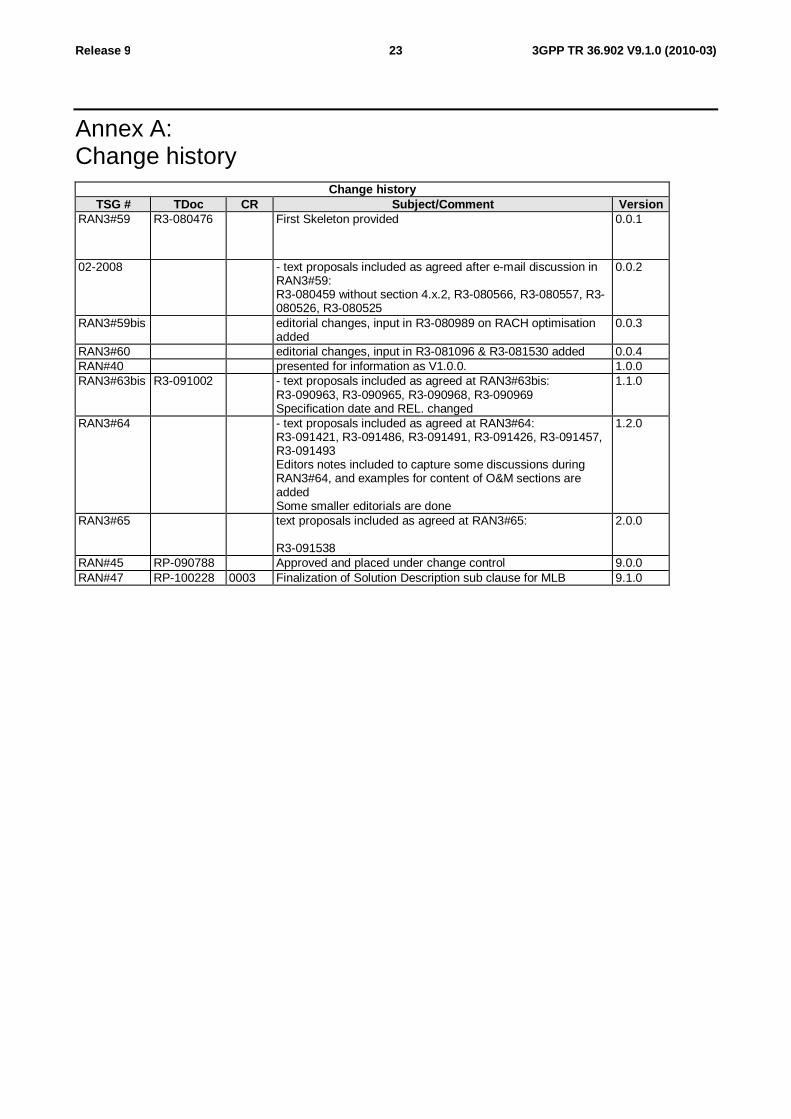
Annex A: Change history
Change history TSG # TDoc CR Subject/Comment Version
RAN3#59 R3-080476 First Skeleton provided 0.0.1
02-2008 - text proposals included as agreed after e-mail discussion in RAN3#59: R3-080459 without section 4.x.2, R3-080566, R3-080557, R3-080526, R3-080525
0.0.2
RAN3#59bis editorial changes, input in R3-080989 on RACH optimisation added
0.0.3
RAN3#60 editorial changes, input in R3-081096 & R3-081530 added 0.0.4 RAN#40 presented for information as V1.0.0. 1.0.0 RAN3#63bis R3-091002 - text proposals included as agreed at RAN3#63bis:
R3-090963, R3-090965, R3-090968, R3-090969 Specification date and REL. changed
1.1.0
RAN3#64 - text proposals included as agreed at RAN3#64: R3-091421, R3-091486, R3-091491, R3-091426, R3-091457, R3-091493 Editors notes included to capture some discussions during RAN3#64, and examples for content of O&M sections are added Some smaller editorials are done
1.2.0
RAN3#65 text proposals included as agreed at RAN3#65: R3-091538
2.0.0
RAN#45 RP-090788 Approved and placed under change control 9.0.0 RAN#47 RP-100228 0003 Finalization of Solution Description sub clause for MLB 9.1.0