technical report - 株式会社qt · technical report 3rd generation ... rnc ue figure 1: ......
TRANSCRIPT
3GPP TR 25.849 V4.0.0 (2001-03)Technical Report
3rd Generation Partnership Project;Technical Specification Group Radio Access Network;
DSCH power control improvement in soft handover(Release 4)
The present document has been developed within the 3rd Generation Partnership Project (3GPP TM) and may be further elaborated for the purposes of 3GPP. The present document has not been subject to any approval process by the 3GPP Organisational Partners and shall not be implemented. This Specification is provided for future development work within 3GPP only. The Organisational Partners accept no liability for any use of this Specification.Specifications and reports for implementation of the 3GPP TM system should be obtained via the 3GPP Organisational Partners' Publications Offices.

3GPP
3GPP TR 25.849 V4.0.0 (2001-03)2Release 4
Keywords
3GPP
Postal address
3GPP support office address 650 Route des Lucioles - Sophia Antipolis
Valbonne - FRANCE Tel.: +33 4 92 94 42 00 Fax: +33 4 93 65 47 16
Internet http://www.3gpp.org
Copyright Notification
No part may be reproduced except as authorized by written permission. The copyright and the foregoing restriction extend to reproduction in all media.
© 2001, 3GPP Organizational Partners (ARIB, CWTS, ETSI, T1, TTA,TTC).
All rights reserved.
3GPP
3GPP TR 25.849 V4.0.0 (2001-03)3Release 4
Contents Foreword ............................................................................................................................................................5 1 Scope ........................................................................................................................................................6 2 References ................................................................................................................................................6 3 Definitions, symbols and abbreviations ...................................................................................................6 3.1 Definitions............................................................................................................................................................... 6 3.2 Symbols................................................................................................................................................................... 6 3.3 Abbreviations .......................................................................................................................................................... 6 4 Introduction ..............................................................................................................................................7 4.1 Fast DSCH power control combined with SSDT .................................................................................................... 7 5 Requirements............................................................................................................................................8 6 Study Areas ..............................................................................................................................................8 6.1 General .................................................................................................................................................................... 8 6.2 New Information ..................................................................................................................................................... 8 6.3 Example Scenario.................................................................................................................................................... 9 6.3.1 DSCH Power Control Initiation when the RL Setup with DSCH...................................................................... 9 6.3.2 DSCH Power Control Initiation when the RL Reconfiguration with new DSCH ........................................... 10 6.3.3 DSCH Power Control Initiation/Termination when the RL Reconfiguration with DSCH to modify.............. 11 6.4 Open Items ............................................................................................................................................................ 11 7 Agreements and associated contributions ..............................................................................................12 7.1 General .................................................................................................................................................................. 12 7.2 New Information ................................................................................................................................................... 12 7.3 Example Scenario.................................................................................................................................................. 12 8 Specification Impact and associated Change Requests ..........................................................................12 8.1 Impacts on RNSAP (TS25.423) ............................................................................................................................ 12 8.1.1 Radio Link Setup procedure ............................................................................................................................ 12 8.1.1.1 Radio Link Setup ............................................................................................................................................. 12 8.1.1.2 General............................................................................................................................................................. 12 8.1.1.3 Successful Operation ....................................................................................................................................... 13 8.1.2 Synchronised Radio Link Reconfiguration Preparation procedure.................................................................. 16 8.1.2.1 General............................................................................................................................................................. 16 8.1.2.2 Successful Operation ....................................................................................................................................... 16 8.1.3 RADIO LINK SETUP REQUEST message.................................................................................................... 22 8.1.4 RADIO LINK SETUP REQUEST .................................................................................................................. 23 8.1.4.1 FDD Message .................................................................................................................................................. 23 8.1.5 RADIO LINK RECONFIGURATION PREPARE message........................................................................... 24 8.1.6 RADIO LINK RECONFIGURATION PREPARE......................................................................................... 25 8.1.6.1 FDD Message .................................................................................................................................................. 25 8.1.7 DSCH FDD Information.................................................................................................................................. 26 8.1.7.1 DSCH FDD Information.................................................................................................................................. 26 8.1.8 NEW IEs.......................................................................................................................................................... 27 8.1.8.1 Enhanced DSCH PC ........................................................................................................................................ 27 8.1.8.2 Enhanced DSCH PC Counter .......................................................................................................................... 27 8.1.8.3 Enhanced DSCH PC Indicator......................................................................................................................... 27 8.1.8.4 Enhanced DSCH PC Wnd ............................................................................................................................... 28 8.1.8.5 Enhanced DSCH Power Offset ........................................................................................................................ 28 8.1.8.6 SSDT Cell Identity for EDSCHPC .................................................................................................................. 28 8.2 Impacts on NBAP (TS 25.433).............................................................................................................................. 28 8.2.1 Radio Link Setup procedure ............................................................................................................................ 28 8.2.2 Radio Link Setup ............................................................................................................................................. 28 8.2.2.1 General............................................................................................................................................................. 28 8.2.2.2 Successful Operation ....................................................................................................................................... 29 8.2.3 Synchronised Radio Link Reconfiguration Preparation procedure.................................................................. 32

3GPP
3GPP TR 25.849 V4.0.0 (2001-03)4Release 4
8.2.4 Synchronised Radio Link Reconfiguration Preparation................................................................................... 32 8.2.4.1 General............................................................................................................................................................. 32 8.2.4.2 Successful Operation ....................................................................................................................................... 32 8.2.5 RADIO LINK SETUP REQUEST message.................................................................................................... 37 8.2.6 RADIO LINK SETUP REQUEST .................................................................................................................. 38 8.2.6.1 FDD message................................................................................................................................................... 38 8.2.7 RADIO LINK RECONFIGURATION PREPARE message........................................................................... 40 8.2.8 RADIO LINK RECONFIGURATION PREPARE......................................................................................... 40 8.2.8.1 FDD Message .................................................................................................................................................. 40 8.2.9 New IE............................................................................................................................................................. 42 8.2.9.1 DSCH FDD Common Information.................................................................................................................. 42 8.2.9.2 Enhanced DSCH PC ........................................................................................................................................ 42 8.2.9.3 Enhanced DSCH PC Counter .......................................................................................................................... 43 8.2.9.4 Enhanced DSCH PC Indicator......................................................................................................................... 43 8.2.9.5 Enhanced DSCH PC Wnd ............................................................................................................................... 43 8.2.9.6 Enhanced DSCH Power Offset ........................................................................................................................ 43 8.2.9.7 SSDT Cell Identity for EDSCHPC .................................................................................................................. 43
Annex A: Change history...............................................................................................................................44
3GPP
3GPP TR 25.849 V4.0.0 (2001-03)5Release 4
Foreword This Technical Report has been produced by the 3rd Generation Partnership Project (3GPP).
The contents of the present document are subject to continuing work within the TSG and may change following formal TSG approval. Should the TSG modify the contents of the present document, it will be re-released by the TSG with an identifying change of release date and an increase in version number as follows:
Version x.y.z
where:
x the first digit:
1 presented to TSG for information;
2 presented to TSG for approval;
3 or greater indicates TSG approved document under change control.
y the second digit is incremented for all changes of substance, i.e. technical enhancements, corrections, updates, etc.
z the third digit is incremented when editorial only changes have been incorporated in the document.

3GPP
3GPP TR 25.849 V4.0.0 (2001-03)6Release 4
1 Scope The present document is for part of the Release 4 work item "DSCH power control improvement in soft handover".
2 References The following documents contain provisions which, through reference in this text, constitute provisions of the present document.
• References are either specific (identified by date of publication, edition number, version number, etc.) or non-specific.
• For a specific reference, subsequent revisions do not apply.
• For a non-specific reference, the latest version applies. In the case of a reference to a 3GPP document (including a GSM document), a non-specific reference implicitly refers to the latest version of that document in the same Release as the present document.
[1] 3GPP TR 25.841: "DSCH power control improvement in soft handover".
[2] 3GPP TS 25.423: "UTRAN Iur interface RNSAP signalling".
[3] 3GPP TS 25.433: "UTRAN Iub interface NBAP signalling".
[4] 3GPP TS 25.435: "UTRAN Iub interface user plane protocols for CCH data streams".
[5] 3GPP TS 25.214: "Physical layer procedures (FDD)".
3 Definitions, symbols and abbreviations
3.1 Definitions Void.
3.2 Symbols Void.
3.3 Abbreviations For the purposes of the present document, the following abbreviations apply:
DCH Dedicated Channel DPCCH Dedicated Physical Control Channel FBI Feedback Information PDSCH Physical Downlink Shared Channel SSDT Site Selection Diversity Transmission SHO Soft Handover DSCH Downlink Shared Channel
3GPP
3GPP TR 25.849 V4.0.0 (2001-03)7Release 4
4 Introduction
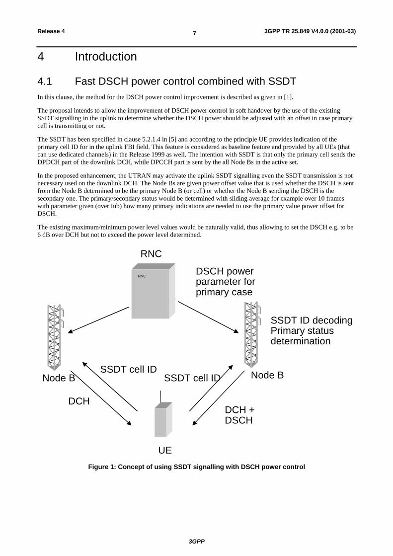
4.1 Fast DSCH power control combined with SSDT In this clause, the method for the DSCH power control improvement is described as given in [1].
The proposal intends to allow the improvement of DSCH power control in soft handover by the use of the existing SSDT signalling in the uplink to determine whether the DSCH power should be adjusted with an offset in case primary cell is transmitting or not.
The SSDT has been specified in clause 5.2.1.4 in [5] and according to the principle UE provides indication of the primary cell ID for in the uplink FBI field. This feature is considered as baseline feature and provided by all UEs (that can use dedicated channels) in the Release 1999 as well. The intention with SSDT is that only the primary cell sends the DPDCH part of the downlink DCH, while DPCCH part is sent by the all Node Bs in the active set.
In the proposed enhancement, the UTRAN may activate the uplink SSDT signalling even the SSDT transmission is not necessary used on the downlink DCH. The Node Bs are given power offset value that is used whether the DSCH is sent from the Node B determined to be the primary Node B (or cell) or whether the Node B sending the DSCH is the secondary one. The primary/secondary status would be determined with sliding average for example over 10 frames with parameter given (over Iub) how many primary indications are needed to use the primary value power offset for DSCH.
The existing maximum/minimum power level values would be naturally valid, thus allowing to set the DSCH e.g. to be 6 dB over DCH but not to exceed the power level determined.
SSDT cell IDSSDT cell ID
DCHDCH +DSCH
DSCH powerparameter forprimary case
RNC
Node B Node B
SSDT ID decodingPrimary statusdetermination
RNC
UE
Figure 1: Concept of using SSDT signalling with DSCH power control
3GPP
3GPP TR 25.849 V4.0.0 (2001-03)8Release 4
5 Requirements Iub/Iur signalling shall fully support DSCH Power Control improvement during soft handover which is defined in [1] and provide the proper parameters to perform this function in the way as decided in WG1, leading group of this work item.
6 Study Areas
6.1 General For the Iub/Iur (NBAP/RNSAP) specifications [3] and [2] the power offset parameters for the primary case with respect to the power value given per each frame in the FP in [4] and the averaging window parameters for the primary/secondary status determination from the SSDT commands sent in the uplink FBI (Feedback Information) field, would be needed.
For the Iub/Iur the following IEs would be needed to indicate improved DSCH PC activation which is very similar with the way of SSDT activation (e.g. Enhanced DSCH PC Indication IE).
For the averaging window parameters at Node B the range [1..10] frames and [1..50] primary SSDT commands are proposed (the latter range is larger as there can be from 1to 5 updates of SSDT status per frame depending on the SSDT ID length).
DSCH power control improvement during soft handover function and SSDT can be used at the same time.
6.2 New Information The parameters to be needed for this function are as followings:
1) for Primary cell selection: averaging window, primary cell selection counter, SSDT cell id for DSCH power control;
2) for activation and deactivation: enhanced DSCH PC indicator;
3) for DSCH power control: additional power offset.

3GPP
3GPP TR 25.849 V4.0.0 (2001-03)9Release 4
6.3 Example Scenario
6.3.1 DSCH Power Control Initiation when the RL Setup with DSCH
R N SA P R N SA P
4. R adio L ink SetupR esponse
N B A P N B A P3. R adio L ink Setup R esponse
D ecision toinitia te D SC H P C
Im provem entduring R L setup
R R CR R C6. D C C H : A ctive Set U pdate C om plete
R R CR R C5. D C C H : A ctive Set U pdate C om m and
[In form ation forD SC H P C Im provem ent]
U E N ode BD rift R N S
N ode BServing R N S
D riftR N C
ServingR N C
R N SA P R N SA P
1. R adio L ink SetupR equest
[SSD T C ell Identity forE D SC H P C , E nhanced
D SC H PC W nd,E nhanced D SC H P CC ounter, E nhanced
D SC H Power O ffset]
N B A P N B A P2. R adio L ink Setup R equest
[E nhanced D SC H Indicator, SSD T C ellIdentity for E D SC H PC ,E nhanced D SC H P C
W nd, E nhanced D SC H PC C ounter,E nhanced D SC H P ower O ffset]
1. SRNC decides to setup a radio link including DSCH which improved power control will be applied on. In
Radio Link Setup Request, SRNC will provides necessary parameters [SSDT Cell Identity for EDSCHPC, Enhanced DSCH PC Wnd, Enhanced DSCH PC Counter, Enhanced DSCH Power Offset].
2. DRNC sends Radio Link Setup Request to Node B with the parameters which SRNC provided [Enhanced DSCH PC Indicator, SSDT Cell Identity for EDSCHPC, Enhanced DSCH PC Wnd, Enhanced DSCH PC Counter, Enhanced DSCH Power Offset].
3. Node B sends Radio Link Setup Response. 4. DRNC sends RNSAP message Radio Link Setup Response to SRNC. 5. SRNC sends RRC message Active Set Update to UE with proper parameter(s) for DSCH Power Control
Improvement. 6. UE acknowledges with RRC message Active Set Update Complete.
Figure 2

3GPP
3GPP TR 25.849 V4.0.0 (2001-03)10Release 4
6.3.2 DSCH Power Control Initiation when the RL Reconfiguration with new DSCH
R N SA P R N SA P
4. R adio L inkR econfiguration R eady
N B A P N B A P3. R adio L ink R econfiguration R eady
D ecision toinitiate D SC H P C
Im provem entduring R L setup
R R CR R C8. D C C H : A ctive Set U pdate C om plete
R R CR R C7. D C C H : A ctive Set U pdate C om m and
[In form ation forD SC H P C Im provem ent]
U E N ode BD rift R N S
N ode BServing R N S
D riftR N C
ServingR N C
R N SA P R N SA P
1. R adio L inkR econfiguration P repare
[SSD T C ell Identity forE D SC H P C , E nhanced
D SC H PC W nd,E nhanced D SC H P CC ounter, E nhanced
D SC H Power O ffset]
N B A PN B A P2. R adio L ink R econfiguration P repare
[E nhanced D SC H PC Indicator, SSD T C ellIdentity for E D SC H PC , E nhanced D SC H P C
W nd, E nhanced D SC H PC C ounter,E nhanced D SC H P ower O ffset]
R N SA P R N SA P
5. R adio L inkR econfiguration C om m it
N B A PN B A P6. R adio L ink R econfiguration C om m it
1. SRNC decides to add a DSCH which improved power control will be applied on. In Radio Link Reconfiguration Prepare, SRNC will provides necessary parameters [SSDT Cell Identity for EDSCHPC, Enhanced DSCH PC Wnd, Enhanced DSCH PC Counter, Enhanced DSCH Power Offset].
2. DRNC sends Radio Link Reconfiguration Prepare to Node B with the parameters which SRNC provided [Enhanced DSCH PC Indicator, SSDT Cell Identity for EDSCHPC, Enhanced DSCH PC Wnd, Enhanced DSCH PC Counter, Enhanced DSCH Power Offset].
3. Node B sends Radio Link Reconfiguration Ready. 4. DRNC sends RNSAP message Radio Link Reconfiguration Ready to SRNC. 5. SRNC sends Radio Link Reconfiguration Commit. 6. DRNC sends Radio Link Reconfiguration Commit. 7. SRNC sends RRC message Active Set Update to UE with proper parameter(s) for DSCH Power Control
Improvement. 8. UE acknowledges with RRC message Active Set Update Complete.
Figure 3

3GPP
3GPP TR 25.849 V4.0.0 (2001-03)11Release 4
6.3.3 DSCH Power Control Initiation/Termination when the RL Reconfiguration with DSCH to modify
R N SA P R N SA P
4. R adio L inkR econfiguration R eady
N B A P
N B A P N B A P3. R adio L ink R econfiguration R eady
D ecision toinitiate D SC H P C
Im provem entduring R L setup
R R CR R C8. D C C H : P hysical C hannel R econfiguration C om plete
R R CR R C7. D C C H : P hysical C hannel R econfiguration
[In form ation forD SC H P C Im provem ent]
U E N ode BD rift R N S
N ode BServing R N S
D riftR N C
ServingR N C
R N SA P R N SA P
1. R adio L inkR econfiguration P repare
[E nhanced D SC H P CIndicator, SSD T C ell
Identity fo r E D SC H P C ,E nhanced D SC H P C
W nd, E nhanced D SC HP C C ounter, E nhancedD SC H P ower O ffset]
N B A P2. R ad io Link R econfiguration P repare
[E nhanced D SC H Indicator, SSD T C ellIdentity fo r E D SC H P C , E nhanced D SC H P C
W nd, E nhanced D SC H P C C ounter,E nhanced D SC H P ower O ffset]
R N SA P R N SA P
5. R adio L inkR econfiguration C om m it
N B A PN B A P6. R ad io L ink R econfiguration C om m it
1. SRNC decides to initiate/terminate a DSCH power control improvement to the existing DSCH. In Radio Link Reconfiguration Prepare, SRNC will provides necessary parameters [Enhanced DSCH PC indicator, SSDT Cell Identity for EDSCHPC, Enhanced DSCH PC Wnd, Enhanced DSCH PC Counter, Enhanced DSCH Power Offset].
2. DRNC sends Radio Link Reconfiguration Prepare to Node B with the parameters which SRNC provided [Enhanced DSCH PC indicator, SSDT Cell Identity for EDSCHPC, Enhanced DSCH PC Wnd, Enhanced DSCH PC Counter, Enhanced DSCH Power Offset].
3. Node B sends Radio Link Reconfiguration Ready. 4. DRNC sends RNSAP message Radio Link Reconfiguration Ready to SRNC. 5. SRNC sends Radio Link Reconfiguration Commit. 6. DRNC sends Radio Link Reconfiguration Commit. 7. SRNC sends RRC message Physical Channel Reconfiguration Complete to UE with proper
parameter(s) for DSCH Power Control Improvement. 8. UE acknowledges with RRC message Physical Channel Reconfiguration Complete.
Figure 4
6.4 Open Items Void.
3GPP
3GPP TR 25.849 V4.0.0 (2001-03)12Release 4
7 Agreements and associated contributions
7.1 General The description in clause 6.1 was agreed.
7.2 New Information It was agreed to use IEs which are described in clause 6.2 to support DSCH power control improvement during soft handover.
7.3 Example Scenario The scenarios described in clause 6.3 were agreed. I.e, the followings were agreed too.
1) To initiate DSCH power control improvement function during soft handover, RADIO LINK SETUP REQUEST message (RNSAP/NBAP) and RADIO LINK RECONFIGURATION PREPARE message shall be used.
2) To initiate DSCH power control improvement function during soft handover, parameters [Enhanced DSCH PC indicator(NBAP only), SSDT Cell Identity for EDSCHPC, Enhanced DSCH PC Wnd, Enhanced DSCH PC Counter, and Enhanced DSCH Power Offset information shall be delivered to Node B from SRNC].
3) To initiate DSCH power control improvement function during soft handover for the existing DSCH, Enhanced DSCH PC Indicator, SSDT Cell Identity for EDSCHPC, Enhanced DSCH PC Wnd, Enhanced DSCH PC Counter, and Enhanced DSCH Power Offset information shall be delivered in RADIO LINK RECONFIGURATION PREPARE message. And Enhanced DSCH PC Wnd, Enhanced DSCH PC Counter, and Enhanced DSCH Power Offset IEs shall be conditional field based on the value of Enhanced DSCH PC Indicator IE.
4) To terminate DSCH power control improvement during soft handover, Enhanced DSCH PC Indicator information shall be delivered in RADIO LINK RECONFIGURATION PREPARE message.
8 Specification Impact and associated Change Requests
This clause is intended to list the affected specifications and the related agreed Change Requests. It also lists the possible new specifications that may be needed for the completion of the Work Task.
8.1 Impacts on RNSAP (TS25.423)
8.1.1 Radio Link Setup procedure
8.1.1.1 Radio Link Setup
8.1.1.2 General
This procedure is used for establishing the necessary resources in the DRNS for one or more radio links.
The connection-oriented service of the signalling bearer shall be established in conjunction with this procedure.

3GPP
3GPP TR 25.849 V4.0.0 (2001-03)13Release 4
8.1.1.3 Successful Operation
SRNC
RADIO LINK SETUP RESPONSE
RADIO LINK SETUP REQUEST
DRNC
Figure 5: Radio Link Setup procedure: Successful Operation
When the SRNC makes an algorithmic decision to add the first cell or set of cells from a DRNS to the active set of a specific RRC connection, the RADIO LINK SETUP REQUEST message is sent to the corresponding DRNC to request setup of the radio link(s).
If no D-RNTI IE was included in the RADIO LINK SETUP REQUEST message, the DRNC shall assign a new D-RNTI for this UE.
[FDD - The First RLS Indicator IE indicates if the concerning RL shall be considered part of the first RLS established towards this UE. If the First RLS indicator IE is set to "first RLS", the DRNS shall use a TPC pattern of n*"01" + "1" in the DL of the concerning RL and all RLs which are part of the same RLS, until UL synchronisation is achieved on the Uu. The TPC pattern shall continuously be repeated but shall be restarted at the beginning of every frame with CFNmod4=0. For all other RLs, the DRNS shall use a TPC pattern of all "1"'s in the DL until UL synchronisation is achieved on the Uu.]
[FDD - The Diversity Control Field IE indicates for each RL except for the first RL whether the DRNS shall combine the RL with any of the other RLs or not on the Iur. If the Diversity Control Field IE is set to "May" (be combined with another RL), then the DRNS shall decide for any of the alternatives. If the Diversity Control Field IE is set to "Must", the DRNS shall combine the RL with one of the other RL. When an RL is to be combined the DRNS shall choose which RL(s) to combine it with.]
[FDD - If the Propagation Delay IE is included, the DRNS may use this information to speed up the detection of L1 synchronisation.]
If the RADIO LINK SETUP REQUEST message includes the Allowed Queuing Time IE the DRNS may queue the request the time corresponding to the value of the Allowed Queuing Time IE before starting to execute the request.
[FDD - If the Initial DL TX Power IE and Uplink SIR Target IE are present in the message, the DRNS shall use the indicated DL TX Power and Uplink SIR Target as initial value. If the value of the Initial DL TX Power IE is outside the configured DL TX power range, the DRNS shall apply these constrains when setting the initial DL TX power. The DRNS shall also include the configured DL TX power range defined by Maximum DL TX Power IE and Minimum DL TX Power IE in the RADIO LINK SETUP RESPONSE message.]
[FDD - If the Primary CPICH Ec/No IE is present, the DRNC should use the indicated value when deciding the Initial DL TX Power.]
[TDD - If the Primary CCPCH RSCP IE and/or the DL Time Slot ISCP Info IE are present, the DRNC should use the indicated values when deciding the Initial DL TX Power.]
[FDD – If the received Limited Power Increase IE is set to 'Used', the DRNS shall, if supported, use Limited Power Increase according to ref. [10] clause 5.2.1 for the inner loop DL power control.]
[FDD – If the received Inner Loop DL PC Status IE is set to "Active", the DRNS shall activate the inner loop DL power control for all RLs. If Inner Loop DL PC Status IE is set to "Inactive", the DRNS shall deactivate the inner loop DL power control for all RLs according to ref. [10].]
[FDD – The DRNS shall start the DL transmission using the indicated DL TX power level (if received) or the decided DL TX power level on each DL channelisation code of a RL until UL synchronisation is achieved for the concerning RLS or a DL POWER CONTROL REQUEST message is received. No innerloop power control or power balancing shall be performed during this period. The DL power shall then vary according to the inner loop power control (see ref. [10] clause 5.2.1.2) with DPC_MODE=0 and the power control procedure (see clause 8.3.7).]

3GPP
3GPP TR 25.849 V4.0.0 (2001-03)14Release 4
[TDD – The DRNS shall start the DL transmission using the decided DL TX power level on each DL channelisation code and on each Time Slot of a RL until UL synchronisation is achieved for the concerning RL. No innerloop power control shall be performed during this period. The DL power shall then vary according to the inner loop power control (see ref. [22] clause 4.2.3.3).]
[TDD - If the DCH Information IE is present in RADIO LINK SETUP REQUEST message, the DRNS shall configure the new DCHs according to the parameters given in the message.]
If the RADIO LINK SETUP REQUEST message includes a DCH Information IE with multiple DCH Specific Info IEs then the DRNS shall treat the DCHs in the DCH Information IE as a set of co-ordinated DCHs.
[FDD - For DCHs which do not belong to a set of co-ordinated DCHs with the QE-Selector IE set to "selected ", the Transport channel BER from that DCH shall be the base for the QE in the UL data frames. If no Transport channel BER is available for the selected DCH the Physical channel BER shall be used for the QE, ref. [4]. If the QE-Selector is set to "non-selected ", the Physical channel BER shall be used for the QE in the UL data frames, ref. [4].]
For a set of co-ordinated DCHs the Transport channel BER from the DCH with the QE-Selector IE set to "selected " shall be used for the QE in the UL data frames, ref. [4]. [FDD - If no Transport channel BER is available for the selected DCH the Physical channel BER shall be used for the QE, ref. [4]. If all DCHs have QE-Selector IE set to "non-selected " the Physical channel BER shall be used for the QE, ref. [4].]
The DRNS shall prioritise resource allocation for the RL(s) to be established according to annex A.
The Frame Handling Priority IE defines the priority level that should be used by the DRNS to prioritise the discard/delay of the data frames of the DCH and DSCH (if any).
The DRNS shall use the included UL DCH FP Mode IE for a DCH or a set of co-ordinated DCHs as the new DCH FP Mode in the Uplink of the user plane for the DCH or the set of co-ordinated DCHs.
The DRNS shall use the included ToAWS IE for a DCH or a set of co-ordinated DCHs as the new Time of Arrival Window Start Point in the user plane for the DCH or the set of co-ordinated DCHs.
The DRNS shall use the included ToAWE IE for a DCH or a set of co-ordinated DCHs as the new Time of Arrival Window End Point in the user plane for the DCH or the set of co-ordinated DCHs.
[FDD - If the RADIO LINK SETUP REQUEST message includes the SSDT Cell Identity IE, the DRNS shall activate SSDT, if supported, using the SSDT Cell Identity IE and SSDT Cell Identity Length IE.]
[FDD - If the RADIO LINK SETUP REQUEST message includes the SSDT Cell Identity for EDSCHPC IE, the DRNS shall activate enhanced DSCH power control, if supported, using the SSDT Cell Identity for EDSCHPC IE and SSDT Cell Identity Length IE as well as Enhanced DSCH PC IE. If the RADIO LINK SETUP REQUEST message includes both SSDT Cell Identity IE and SSDT Cell Identity for EDSCHPC IE, then DRNS shall ignore the SSDT Cell Identity for EDSCHPC IE.]
[FDD - If the RADIO LINK SETUP REQUEST message includes the Transmission Gap Pattern Sequence Information IE, the DRNS shall store the information about the Transmission Gap Pattern Sequences to be used in the Compressed Mode Configuration. This Compressed Mode Configuration shall be valid in the DRNS until the next Compressed Mode Configuration is configured in the DRNS or last Radio Link is deleted.]
[FDD - If the RADIO LINK SETUP REQUEST message includes the Transmission Gap Pattern Sequence Information IE and the Active Pattern Sequence Information IE, the DRNS shall immediately activate the indicated Transmisson Gap Pattern Sequences: for each sequence the TGCFN refers to latest passed CFN with that value. If during the compressed mode measurement the gaps of two or more pattern sequences overlap, the DRNS shall behave as specified in clause 8.3.9.]
[TDD - The DRNS shall use the list of RB Identities in the RB Info IE in the USCH information IE to map each RB Identity IE to the corresponding USCH.]
At the reception of the RADIO LINK SETUP REQUEST message, DRNS allocates requested type of channelisation codes and other physical channel resources for each RL and assigns a binding identifier and a transport layer address for each DCH or set of co-ordinated DCHs and for each DSCH [TDD - and USCH]. This information shall be sent to the SRNC in the message RADIO LINK SETUP RESPONSE when all the RLs have been successfully setup.
If the DSCH Information IE is included in the RADIO LINK SETUP REQUEST message, the DRNC shall establish the requested DSCH's [FDD - on the RL indicated by the PDSCH RL ID IE]. In addition, the DRNC shall send a valid set
3GPP
3GPP TR 25.849 V4.0.0 (2001-03)15Release 4
of DSCH Scheduling Priority IE and MAC-c/sh SDU Length IE parameters to the SRNC in the message RADIO LINK SETUP RESPONSE message.
[FDD - If the Initial DL TX Power and the Uplink SIR Target IEs are not present in the RADIO LINK SETUP REQUEST message, then DRNC shall include the determined initial Uplink SIR Target in the RADIO LINK SETUP RESPONSE message.]
[FDD – When more than one DL DPDCH are assigned per RL, the segmented physical channel shall be mapped on to DL DPDCHs according to [8]. When p number of DL DPDCHs are assigned to each RL, the first pair of DL Scrambling Code and FDD DL Channelisation Code Number corresponds to "PhCH number 1", the second to "PhCH number 2", and so on until the pth to "PhCH number p".]
[FDD – For each RL not having a common generation of the TPC commands in the DL with another RL, the DRNS shall assign the RL Set ID IE included in the RADIO LINK SETUP RESPONSE message a value that uniquely identifies the RL Set within the UE context.]
[FDD – For all RLs having a common generation of the TPC commands in the DL with another RL, the DRNS shall assign the RL Set ID IE included in the RADIO LINK SETUP RESPONSE message the same value. This value shall uniquely identify the RL Set within the UE context.]
[FDD - In the case of combining one or more RLs the DRNC shall indicate in the RADIO LINK SETUP RESPONSE message with the Diversity Indication IE that the RL is combined with another RL. In this case the Reference RL ID IE shall be included to indicate with which RL the combination is performed. The Reference RL ID IE shall be included for all but one of the combined RLs, for which the Transport Layer Address IE and the Binding ID IE shall be included.]
[FDD - In the case of not combining an RL with another RL, the DRNC shall indicate in the RADIO LINK SETUP RESPONSE message with the Diversity Indication IE that no combining is performed. In this case the DRNC shall include both the Transport Layer Address IE and the Binding ID IE for the transport bearer to be established for each DCH and DSCH of the RL in the RADIO LINK SETUP RESPONSE message.]
[TDD - The DRNC shall always include in the RADIO LINK SETUP RESPONSE message both the Transport Layer Address IE and the Binding ID IE for the transport bearer to be established for each DCH, DSCH and USCH of the RL.]
In case of a set of coordinated DCHs requiring a new transport bearer on Iur the Binding ID IE and the Transport Layer Address IE shall be included only for one of the DCH in the set of co-ordinated DCHs.
[FDD – If the cell in which the RL is being set up is capable to provide Close loop Tx diversity, the DRNC shall include the Closed Loop Timing Adjustment Mode IE in the RADIO LINK SETUP RESPONSE message indicating the configured Closed loop timing adjustment mode of the cell.]
For any cell neighbouring a cell in which a RL was established, the DRNS shall also provide the SRNC with the UTRAN Cell Identifier (UC-Id), the Frequency Number, the [FDD - Primary Scrambling Code], the [TDD - Cell Parameter ID, the Sync Case, the SCH Time Slot information, the Block STTD Indicator] and the node identification of the CN nodes connected to the RNC controlling the neighbouring cell if the UMTS neighbouring cell is not controlled by the DRNC. In addition, if the information is available, the DRNC shall also provide the [FDD - CPICH Power level, cell individual offset]/[TDD - PCCPCH Power level, DPCH Constant Value] and Frame Offset of the UMTS neighbouring cell.
If a UMTS neighbouring cell is controlled by another RNC, the DRNC shall report also the node identifications (i.e. RNC and CN domain nodes) of the RNC controlling the UMTS neighbouring cell. [FDD – If the information is available, the DRNC shall include the Tx Diversity Indicator IE and Tx diversity capability (i.e. STTD Support Indicator IE, Closed Loop Mode1 Support Indicator IE, and Closed Loop Mode2 Support Indicator IE) in the Neighbouring FDD Cell Information IE].
If there are GSM neighbouring cells to the cell(s) where a radio link is established, the DRNC shall include the Neighbouring GSM Cell Information IE in the RADIO LINK SETUP RESPONSE message for each of the GSM neighbouring cells. If available the DRNC shall include the GSM Output Power IE in the Neighbouring GSM Cell Information IE.
If no D-RNTI IE was included in the RADIO LINK SETUP REQUEST message, the DRNC shall include the node identifications of the CN Domain nodes that the RNC is connected to (using LAC and RAC of the current cell), and the D-RNTI IE in the RADIO LINK SETUP RESPONSE message.

3GPP
3GPP TR 25.849 V4.0.0 (2001-03)16Release 4
[FDD - If the D-RNTI IE was included the RADIO LINK SETUP REQUEST message the DRNC shall include the Primary Scrambling Code IE, the UL UARFCN IE, the DL UARFCN IE, and the Primary CPICH Power IE in the RADIO LINK SETUP RESPONSE message.]
[FDD - If the DRAC Control IE is set to "requested" in the RADIO LINK SETUP REQUEST message for at least one DCH and if the DRNC supports the DRAC, the DRNC shall indicate in the RADIO LINK SETUP RESPONSE message the Secondary CCPCH Info IE to be received on FACH, for each added Radio Link. If the DRNC does not support DRAC, it shall not provide these IEs in the RADIO LINK SETUP RESPONSE message.]
Depending on local configuration in the DRNS, it may include the geographical co-ordinates of the cell and the UTRAN access point position for each of the established RLs in the RADIO LINK SETUP RESPONSE message.
After sending of the RADIO LINK SETUP RESPONSE message the DRNS shall continuously attempt to obtain UL synchronisation and start reception on the new RL. The DRNS shall start transmission on the new RL after synchronisation is achieved in the DL user plane as specified in ref. [3].
[FDD – When Diversity Mode IE is "STTD", "Closed loop mode1", or "Closed loop mode2", the DRNC shall activate/deactivate the Transmit Diversity to each Radio Link in accordance with Transmit Diversity Indication IE].
[FDD- If the Downlink compressed mode method in one or more Transmission Gap Pattern Sequence is set to 'SF/2' in the RADIO LINK SETUP REQUEST message, the DRNS shall include the Transmission Gap Pattern Sequence Scrambling Code Information IE in the RADIO LINK SETUP RESPONSE message indicating for each DL Channelisation Code whether the alternative scrambling code shall be used or not.]
[FDD –The UL out-of-sync algorithm defined in [10] shall for each of the established RL Set(s) use the maximum value of the parameters N_OUTSYNC_IND and T_RLFAILURE, and the minimum value of the parameters N_INSYNC_IND, that are configured in the cells supporting the radio links of the RL Set.]
For each Radio Link the DRNC shall include the URA ID IE of the cell, the Multiple URAs Indicator IE indicating whether or not the cell belongs to multiple URAs, and the RNC Identity of all other RNCs that are having at least one cell within the URA in the cell in the URA Information IE in the RADIO LINK SETUP RESPONSE message.
8.1.2 Synchronised Radio Link Reconfiguration Preparation procedure
8.1.2.1 General
The Synchronised Radio Link Reconfiguration Preparation procedure is used to prepare a new configuration of all Radio Links related to one UE-UTRAN connection within a DRNS.
This procedure shall use the signalling bearer connection for the relevant UE context.
The Synchronised Radio Link Reconfiguration Preparation procedure shall not be initiated if a Prepared Reconfiguration exists, as defined in clause 3.1.
8.1.2.2 Successful Operation
SRNC
RADIO LINK RECONFIGURATION READY
RADIO LINK RECONFIGURATION PREPAREDRNC
Figure 6: Synchronised Radio Link Reconfiguration Preparation procedure, Successful Operation
The Synchronised Radio Link Reconfiguration Preparation procedure is initiated by the SRNC by sending the RADIO LINK RECONFIGURATION PREPARE message to the DRNC.
Upon reception, the DRNS shall reserve necessary resources for the new configuration of the Radio Link(s) according to the parameters given in the message. Unless specified below, the meaning of parameters is specified in other specifications.
3GPP
3GPP TR 25.849 V4.0.0 (2001-03)17Release 4
If the RADIO LINK RECONFIGURATION PREPARE message includes the Allowed Queuing Time IE the DRNS may queue the request the time corresponding to the value of the Allowed Queuing Time IE before starting to execute the request.
The DRNS shall prioritise resource allocation for the RL(s) to be modified according to annex A.
DCH Modification:
If the RADIO LINK RECONFIGURATION PREPARE message includes any DCHs to Modify IEs then the DRNS shall treat them each as follows:
- If the DCHs to Modify IE includes the UL FP Mode IE for a DCH or a DCH which belongs to a set of co-ordinated DCHs to be modified, the DRNS shall apply the new FP Mode in the Uplink of the user plane forthe DCH or the set of co-ordinated DCHs in the new configuration.
- If the DCHs to Modify IE includes the ToAWS IE for a DCH or a DCH which belongs to a set of co-ordinated DCHs to be modified, the DRNS shall apply the new ToAWS in the user plane for the DCH or the set of co-ordinated DCHs in the new configuration.
- If the DCHs to Modify IE includes the ToAWE IE for a DCH or a DCH which belongs to a set of co-ordinated DCHs to be modified, the DRNS shall apply the new ToAWE in the user plane for the DCH or the set of co-ordinated DCHs in the new configuration.
- If the DCHs to Modify IE includes multiple DCH Specific Info IEs then the DRNS shall treat the DCHs in the DCHs to Modify IE as a set of co-ordinated DCHs. The DRNS shall include these DCHs in the new configuration only if it can include all of them in the new configuration.
- If the DCH Specific Info IE includes the Frame Handling Priority IE for a DCH to be modified, the DRNS should store this information for this DCH in the new configuration. The received Frame Handling Priority should be used when prioritising between different frames in the downlink on the radio interface in congestion situations within the DRNS once the new configuration has been activated.
- If the DCH Specific Info IE includes the Transport Format Set IE for the UL of a DCH to be modified, the DRNS shall apply the new Transport Format Set in the Uplink of this DCH in the new configuration.
- If the DCH Specific Info IE includes the Transport Format Set IE for the DL of a DCH to be modified, the DRNS shall apply the new Transport Format Set in the Downlink of this DCH in the new configuration.
- [FDD - If, in the DCH Specific Info IE, the DRAC Control IE is present and set to "requested" for at least one DCH and if the DRNS supports the DRAC, the DRNC shall indicate in the RADIO LINK RECONFIGURATION READY message the Secondary CCPCH Info IE to be received on FACH, for each Radio Link. If the DRNS does not support DRAC, it shall not provide these IEs in the RADIO LINK RECONFIGURATION READY message.]
- [TDD - If the DCH Specific Info IE includes the CCTrCH ID IE for the UL, the DRNS shall map the DCH onto the referenced UL CCTrCH.]
- [TDD - If the DCH Specific Info IE includes the CCTrCH ID IE for the DL, the DRNS shall map the DCH onto the referenced DL CCTrCH.]
DCH Addition:
If the RADIO LINK RECONFIGURATION PREPARE message includes any DCHs to Add IEs then the DRNS shall treat them each as follows:
- The DRNS shall reserve necessary resources for the new configuration of the Radio Link(s) according to the parameters given in the message and include these DCH in the new configuration.
- If the DCHs to Add IE includes a DCHs to Add IE with multiple DCH Specific Info IEs then the DRNS shall treat the DCHs in the DCHs to Add IE as a set of co-ordinated DCHs. The DRNS shall include these DCHs in the new configuration only if it can include all of them in the new configuration.

3GPP
3GPP TR 25.849 V4.0.0 (2001-03)18Release 4
- [FDD - For DCHs which do not belong to a set of co-ordinated DCHs with the QE-Selector IE set to "selected ", the Transport channel BER from that DCH shall be the base for the QE in the UL data frames. If no Transport channel BER is available for the selected DCH the Physical channel BER shall be used for the QE, ref. [4]. If the QE-Selector is set to "non-selected ", the Physical channel BER shall be used for the QE in the UL data frames, ref. [4].]
- [FDD - For a set of co-ordinated DCHs the Transport channel BER from the DCH with the QE-Selector IE set to "selected " shall be used for the QE in the UL data frames, ref. [4]. [FDD - If no Transport channel BER is available for the selected DCH the Physical channel BER shall be used for the QE, ref. [4]. If all DCHs have QE-Selector IE set to "non-selected " the Physical channel BER shall be used for the QE, ref. [4].]
- The DRNS should store the Frame Handling Priority IE received for a DCH to be added in the new configuration. The received Frame Handling Priority should be used when prioritising between different frames in the downlink on the radio interface in congestion situations within the DRNS once the new configuration has been activated.
- The DRNS shall use the included UL FP Mode IE for a DCH or a set of co-ordinated DCHs to be added as the new FP Mode in the Uplink of the user plane for the DCH or the set of co-ordinated DCHs in the new configuration.
- The DRNS shall use the included ToAWS IE for a DCH or a set of co-ordinated DCHs to be added as the new Time of Arrival Window Start Point in the user plane for the DCH or the set of co-ordinated DCHs in the new configuration.
- The DRNS shall use the included ToAWE IE for a DCH or a set of co-ordinated DCHs to be added as the new Time of Arrival Window End Point in the user plane for the DCH or the set of co-ordinated DCHs in the new configuration.
- [FDD - If the DRAC Control IE is set to "requested" in the DCH Specific Info IE for at least one DCH and if the DRNS supports the DRAC, the DRNC shall indicate in the RADIO LINK RECONFIGURATION READY message the Secondary CCPCH Info IE to be received on FACH, for each Radio Link. If the DRNS does not support DRAC, it shall not provide these IEs in the RADIO LINK RECONFIGURATION READY message.]
DCH Deletion:
If the RADIO LINK RECONFIGURATION PREPARE message includes any DCH to Delete, the DRNS shall not include the referenced DCHs in the new configuration.
If all of the DCHs belonging to a set of co-ordinated DCHs are requested to be deleted, the DRNS shall not include this set of co-ordinated DCHs in the new configuration.
Physical Channel Modification:
[FDD - If the RADIO LINK RECONFIGURATION PREPARE message includes an UL DPCH Information IE then the DRNS shall apply the parameters to the new configuration as follows:]
- [FDD - If the UL DPCH Information IE includes the Uplink Scrambling Code IE, the DRNS shall apply this Uplink Scrambling Code to the new configuration.]
- [FDD - If the UL DPCH Information IE includes the Min UL Channelisation Code Length IE, the DRNS shall apply the new Min UL Channelisation Code Length in the new configuration.]
- [FDD - If the UL DPCH Information IE includes the TFCS IE, the DRNS shall use the TFCS IE for the UL when reserving resources for the uplink of the new configuration. The DRNS shall apply the new TFCS in the Uplink of the new configuration.]
- [FDD - If the UL DPCH Information IE includes the UL DPCCH Slot Format IE, the DRNS shall apply the new Uplink DPCCH Slot Format to the new configuration.]
- [FDD – If the UL DPCH Information IE includes the UL SIR Target IE, the DRNS shall set the UL inner loop power control to the UL SIR target when the new configuration is being used.]
- [FDD – If the UL DPCH Information IE includes the Puncture Limit IE, the DRNS shall apply the value in the uplink of the new configuration.]

3GPP
3GPP TR 25.849 V4.0.0 (2001-03)19Release 4
- [FDD - If the UL DPCH Information IE includes the Diversity Mode IE, the DRNS shall apply diversity according to the given value.]
- [FDD – If the UL DPCH Information IE includes an SSDT Cell Identity Length IE and/or an S-Field Length IE, the DRNS shall apply the values in the new configuration.]
[FDD - If the RADIO LINK RECONFIGURATION PREPARE message includes a DL DPCH Information IE then the DRNS shall apply the parameters to the new configuration as follows:]
- [FDD - If the DL DPCH Information IE includes Number of DL Channelisation Codes IE, the DRNS shall allocate given number of Downlink Channelisation Codes per Radio Link and apply the new Downlink Channelisation Code(s) to the new configuration. Each Downlink Channelisation Code allocated for the new configuration shall be included as a FDD DL Channelisation Code Number IE in the RADIO LINK RECONFIGURATION READY message when sent to the SRNC. If some Transmission Gap Pattern sequences using 'SF/2' method are already initialised in the DRNS, DRNC shall include the Transmission Gap Pattern Sequence Scrambling Code Information IE in the RADIO LINK RECONFIGURATION READY message in case the DRNS selects to change the Scrambling code change method for one or more DL Channelisation Code.]
- [FDD – When more than one DL DPDCH are assigned per RL, the segmented physical channel shall be mapped on to DL DPDCHs according to [8]. When p number of DL DPDCHs are assigned to each RL, the first pair of DL Scrambling Code and FDD DL Channelisation Code Number corresponds to "PhCH number 1", the second to "PhCH number 2", and so on until the pth to "PhCH number p".]
- [FDD - If the DL DPCH Information IE includes the TFCS IE, the DRNS shall use the TFCS IE for the DL when reserving resources for the downlink of the new configuration. The DRNS shall apply the new TFCS in the Downlink of the new configuration.]
- [FDD – If the DL DPCH Information IE includes the DL DPCH Slot Format IE, the DRNS shall apply the new slot format used in DPCH in DL.]
- [FDD – If the DL DPCH Information IE includes the TFCI Signalling Mode IE, the DRNS shall apply the new signalling mode of the TFCI.]
- [FDD – If the DL DPCH Information IE includes the Multiplexing Position IE, the DRNS shall apply the new parameter to define whether fixed or flexible positions of transport channels shall be used in the physical channel.]
- [FDD – If the DL DPCH Information IE includes the Limited Power Increase IE and the IE is set to 'Used', the DRNS shall, if supported, use Limited Power Increase according to ref. [10] clause 5.2.1 for the inner loop DL power control in the new configuration.]
- [FDD – If the DL DPCH Information IE includes the Limited Power Increase IE and the IE is set to 'Not Used', the DRNS shall not use Limited Power Increase for the inner loop DL power control in the new configuration.]
- [FDD: If the RADIO LINK RECONFIGURATION PREPARE message includes the Transmission Gap Pattern Sequence Information IE, the DRNS shall store the new information about the Transmission Gap Pattern Sequences to be used in the new Compressed Mode Configuration.
- [FDD: If the RADIO LINK RECONFIGURATION PREPARE message includes the Transmission Gap Pattern Sequence Information IE and the Downlink compressed mode method in one or more Transmission Gap Pattern Sequence within the Transmission Gap Pattern Sequence Information IE is set to 'SF/2', the DRNC shall include the Transmission Gap Pattern Sequence Scrambling Code Information IE to the RADIO LINK RECONFIGURATION READY message indicating for each Channelisation Code whether the alternative scrambling code shall be used or not].
[TDD - UL/DL CCTrCH Modification]
[TDD - If the RADIO LINK RECONFIGURATION PREPARE message includes any UL CCTrCH to Modify IEs or DL CCTrCH to Modify IEs, then the DRNS shall treat them each as follows:]
[TDD - If any of the UL CCTrCH to Modify IEs or DL CCTrCH to Modify IEs includes any of TFCS IE, TFCI coding IE, Puncture limit IE, or TPC CCTrCH ID IEs the DRNS shall apply these as the new values, otherwise the old values specified for this CCTrCH are still applicable.]
3GPP
3GPP TR 25.849 V4.0.0 (2001-03)20Release 4
- [TDD – The DRNC shall include in the RADIO LINK RECONFIGURATION READY message DPCH information to be modified and the IEs modified if any of Repetition Period IE, Repetition Length IE, TDD DPCH Offset IE or timeslot information was modified. The DRNC shall include timeslot information and the IEs modified if any of Midamble Shift and Burst Type IE, Time Slot IE, TFCI Presence IE or Code information was modified. The DRNC shall include code information if TDD Channelisation Code IE was modified.]
[TDD – UL/DL CCTrCH Addition]
[TDD -If the RADIO LINK RECONFIGURATION PREPARE message includes any UL CCTrCH to Add IEs or DL CCTrCH to Add IEs, the DRNS shall include this CCTrCH in the new configuration.]
[TDD – If the DRNS has reserved the required resources for any requested DPCHs, the DRNC shall include the DPCH information within DPCH to be added in the RADIO LINK RECONFIGURATION READY message. If no DPCH was active before the reconfiguration, and if a valid Rx Timing Deviation measurement is known in DRNC, then the DRNC shall include the Rx Timing Deviation IE in the RADIO LINK RECONFIGURATION READY message.]
[TDD – UL/DL CCTrCH Deletion]
[TDD - If the RADIO LINK RECONFIGURATION PREPARE message includes any UL CCTrCH to Delete IEs or DL CCTrCH to Delete IEs, the DRNS shall remove this CCTrCH in the new configuration.]
SSDT Activation/Deactivation:
- [FDD - If the RL Information IE includes the SSDT Indication IE set to "SSDT Active in the UE", the DRNS shall activate SSDT, if supported, using the SSDT Cell Identity IE in RL Information IE, and the SSDT Cell Identity Length IE in UL DPCH Information IE, in the new configuration. If the RL Information IE includes both SSDT Cell Identity IE and SSDT Cell Identity for EDSCHPC IE, then DRNS shall ignore the SSDT Cell Identity for EDSCHPC IE.]
- [FDD - If the RL Information IE includes the SSDT Indication IE set to "SSDT not Active in the UE", the DRNS shall deactivate SSDT in the new configuration.]
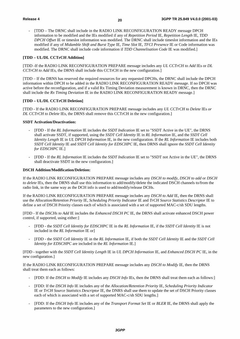
DSCH Addition/Modification/Deletion:
If the RADIO LINK RECONFIGURATION PREPARE message includes any DSCH to modify, DSCH to add or DSCH to delete IEs, then the DRNS shall use this information to add/modify/delete the indicated DSCH channels to/from the radio link, in the same way as the DCH info is used to add/modify/release DCHs.
If the RADIO LINK RECONFIGURATION PREPARE message includes any DSCH to Add IE, then the DRNS shall use the Allocation/Retention Priority IE, Scheduling Priority Indicator IE and TrCH Source Statistics Descriptor IE to define a set of DSCH Priority classes each of which is associated with a set of supported MAC-c/sh SDU lengths.
[FDD - If the DSCHs to Add IE includes the Enhanced DSCH PC IE, the DRNS shall activate enhanced DSCH power control, if supported, using either:]
- [FDD - the SSDT Cell Identity for EDSCHPC IE in the RL Information IE, if the SSDT Cell Identity IE is not included in the RL Information IE or]
- [FDD - the SSDT Cell Identity IE in the RL Information IE, if both the SSDT Cell Identity IE and the SSDT Cell Identity for EDSCHPC are included in the RL Information IE.]
[FDD - together with the SSDT Cell Identity Length IE in UL DPCH Information IE, and Enhanced DSCH PC IE, in the new configuration.]
If the RADIO LINK RECONFIGURATION PREPARE message includes any DSCH to Modify IE, then the DRNS shall treat them each as follows:
- [FDD: If the DSCH to Modify IE includes any DSCH Info IEs, then the DRNS shall treat them each as follows:]
- [FDD: If the DSCH Info IE includes any of the Allocation/Retention Priority IE, Scheduling Priority Indicator IE or TrCH Source Statistics Descriptor IE, the DNRS shall use them to update the set of DSCH Priority classes each of which is associated with a set of supported MAC-c/sh SDU lengths.]
- [FDD: If the DSCH Info IE includes any of the Transport Format Set IE or BLER IE, the DRNS shall apply the parameters to the new configuration.]
3GPP
3GPP TR 25.849 V4.0.0 (2001-03)21Release 4
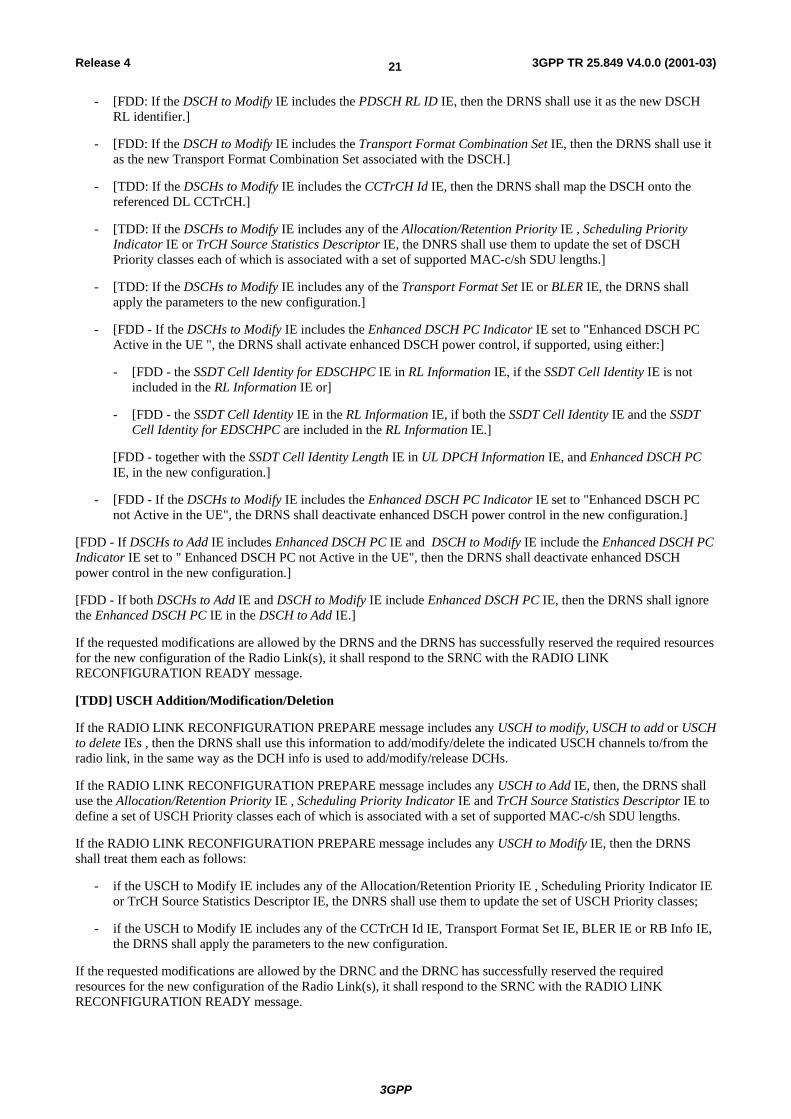
- [FDD: If the DSCH to Modify IE includes the PDSCH RL ID IE, then the DRNS shall use it as the new DSCH RL identifier.]
- [FDD: If the DSCH to Modify IE includes the Transport Format Combination Set IE, then the DRNS shall use it as the new Transport Format Combination Set associated with the DSCH.]
- [TDD: If the DSCHs to Modify IE includes the CCTrCH Id IE, then the DRNS shall map the DSCH onto the referenced DL CCTrCH.]
- [TDD: If the DSCHs to Modify IE includes any of the Allocation/Retention Priority IE , Scheduling Priority Indicator IE or TrCH Source Statistics Descriptor IE, the DNRS shall use them to update the set of DSCH Priority classes each of which is associated with a set of supported MAC-c/sh SDU lengths.]
- [TDD: If the DSCHs to Modify IE includes any of the Transport Format Set IE or BLER IE, the DRNS shall apply the parameters to the new configuration.]
- [FDD - If the DSCHs to Modify IE includes the Enhanced DSCH PC Indicator IE set to "Enhanced DSCH PC Active in the UE ", the DRNS shall activate enhanced DSCH power control, if supported, using either:]
- [FDD - the SSDT Cell Identity for EDSCHPC IE in RL Information IE, if the SSDT Cell Identity IE is not included in the RL Information IE or]
- [FDD - the SSDT Cell Identity IE in the RL Information IE, if both the SSDT Cell Identity IE and the SSDT Cell Identity for EDSCHPC are included in the RL Information IE.]
[FDD - together with the SSDT Cell Identity Length IE in UL DPCH Information IE, and Enhanced DSCH PC IE, in the new configuration.]
- [FDD - If the DSCHs to Modify IE includes the Enhanced DSCH PC Indicator IE set to "Enhanced DSCH PC not Active in the UE", the DRNS shall deactivate enhanced DSCH power control in the new configuration.]
[FDD - If DSCHs to Add IE includes Enhanced DSCH PC IE and DSCH to Modify IE include the Enhanced DSCH PC Indicator IE set to " Enhanced DSCH PC not Active in the UE", then the DRNS shall deactivate enhanced DSCH power control in the new configuration.]
[FDD - If both DSCHs to Add IE and DSCH to Modify IE include Enhanced DSCH PC IE, then the DRNS shall ignore the Enhanced DSCH PC IE in the DSCH to Add IE.]
If the requested modifications are allowed by the DRNS and the DRNS has successfully reserved the required resources for the new configuration of the Radio Link(s), it shall respond to the SRNC with the RADIO LINK RECONFIGURATION READY message.
[TDD] USCH Addition/Modification/Deletion
If the RADIO LINK RECONFIGURATION PREPARE message includes any USCH to modify, USCH to add or USCH to delete IEs , then the DRNS shall use this information to add/modify/delete the indicated USCH channels to/from the radio link, in the same way as the DCH info is used to add/modify/release DCHs.
If the RADIO LINK RECONFIGURATION PREPARE message includes any USCH to Add IE, then, the DRNS shall use the Allocation/Retention Priority IE , Scheduling Priority Indicator IE and TrCH Source Statistics Descriptor IE to define a set of USCH Priority classes each of which is associated with a set of supported MAC-c/sh SDU lengths.
If the RADIO LINK RECONFIGURATION PREPARE message includes any USCH to Modify IE, then the DRNS shall treat them each as follows:
- if the USCH to Modify IE includes any of the Allocation/Retention Priority IE , Scheduling Priority Indicator IE or TrCH Source Statistics Descriptor IE, the DNRS shall use them to update the set of USCH Priority classes;
- if the USCH to Modify IE includes any of the CCTrCH Id IE, Transport Format Set IE, BLER IE or RB Info IE, the DRNS shall apply the parameters to the new configuration.
If the requested modifications are allowed by the DRNC and the DRNC has successfully reserved the required resources for the new configuration of the Radio Link(s), it shall respond to the SRNC with the RADIO LINK RECONFIGURATION READY message.

3GPP
3GPP TR 25.849 V4.0.0 (2001-03)22Release 4
General
The DRNS shall include in the RADIO LINK RECONFIGURATION READY message the Transport Layer Address IE and the Binding ID IE in the DCH Information Response IE for any Transport Channel being added, or any Transport Channel being modified for which a new transport bearer was requested with the Transport Bearer Request Indicator IE. In case of a set of coordinated DCHs requiring a new transport bearer on Iur, the Transport Layer Address IE and the Binding ID IE in the DCH Information Response IE shall be included only for one of the DCH in the set of coordinated DCHs.
In case of a Radio Link being combined with another Radio Link within the DRNS, the Transport Layer Address IE and the Binding ID IE in the DCH Information Response IE shall be included only for one of the combined Radio Links.
If the requested modifications are allowed by the DRNS, and the DRNS has successfully reserved the required resources for the new configuration of the Radio Link(s) it shall respond to the SRNC with the RADIO LINK RECONFIGURATION READY message. When this procedure has been completed successfully there exist a Prepared Reconfiguration, as defined in clause 3.1.
The DRNS decides the maximum and minimum SIR for the uplink of the Radio Link(s) and shall return this in the Maximum Uplink SIR IE and Minimum Uplink SIR IE for each Radio Link in the RADIO LINK RECONFIGURATION READY message.
If the DL TX power upper or lower limit has been re-configured the DRNC shall return this in the Maximum DL TX Power IE and Minimum DL TX Power IE respectively in the RADIO LINK RECONFIGURATION RESPONSE message.
8.1.3 RADIO LINK SETUP REQUEST message To initiate DSCH power control improvement function during soft handover, SSDT Cell Identity for EDSCHPC, , Enhanced DSCH PC Wnd, Enhanced DSCH PC Counter, and Enhanced DSCH Power Offset IEs shall be included in the RADIO LINK SETUP REQUEST message.
3GPP
3GPP TR 25.849 V4.0.0 (2001-03)23Release 4
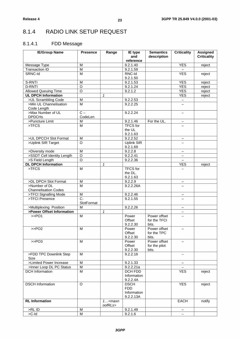
8.1.4 RADIO LINK SETUP REQUEST
8.1.4.1 FDD Message
IE/Group Name Presence Range IE type and
reference
Semantics description
Criticality Assigned Criticality
Message Type M 9.2.1.40 YES reject Transaction ID M 9.2.1.59 – SRNC-Id M RNC-Id
9.2.1.50 YES reject
S-RNTI M 9.2.1.53 YES reject D-RNTI O 9.2.1.24 YES reject Allowed Queuing Time O 9.2.1.2 YES reject UL DPCH Information 1 YES reject
>UL Scrambling Code M 9.2.2.53 – >Min UL Channelisation Code Length
M 9.2.2.25 –
>Max Number of UL DPDCHs
C – CodeLen
9.2.2.24 –
>Puncture Limit M 9.2.1.46 For the UL. – >TFCS M TFCS for
the UL 9.2.1.63
–
>UL DPCCH Slot Format M 9.2.2.52 – >Uplink SIR Target O Uplink SIR
9.2.1.69 –
>Diversity mode M 9.2.2.8 – >SSDT Cell Identity Length O 9.2.2.41 – >S Field Length O 9.2.2.36 –
DL DPCH Information 1 YES reject >TFCS M TFCS for
the DL. 9.2.1.63
–
>DL DPCH Slot Format M 9.2.2.9 – >Number of DL Channelisation Codes
M 9.2.2.26A –
>TFCI Signalling Mode M 9.2.2.46 – >TFCI Presence C-
SlotFormat 9.2.1.55 –
>Multiplexing Position M 9.2.2.26 – >Power Offset Information 1 –
>>PO1 M Power Offset 9.2.2.30
Power offset for the TFCI bits.
–
>>PO2 M Power Offset 9.2.2.30
Power offset for the TPC bits.
–
>>PO3 M Power Offset 9.2.2.30
Power offset for the pilot bits.
–
>FDD TPC Downlink Step Size
M 9.2.2.16 –
>Limited Power Increase M 9.2.1.33 – >Inner Loop DL PC Status M 9.2.2.21a – DCH Information M DCH FDD
Information 9.2.2.4A
YES reject
DSCH Information O DSCH FDD Information 9.2.2.13A
YES reject
RL Information 1…<maxnoofRLs>
EACH notify
>RL ID M 9.2.1.49 – >C-Id M 9.2.1.6 –

3GPP
3GPP TR 25.849 V4.0.0 (2001-03)24Release 4
IE/Group Name Presence Range IE type and
reference
Semantics description
Criticality Assigned Criticality
>First RLS Indicator M 9.2.2.16A - >Frame Offset M 9.2.1.30 – >Chip Offset M 9.2.2.1 – >Propagation Delay O 9.2.2.33 – >Diversity Control Field C –
NotFirstRL 9.2.2.6 –
>Initial DL TX Power C_ifAlone DL Power 9.2.2.10
–
>Primary CPICH Ec/No C_ifAlone 9.2.2.32 – >SSDT Cell Identity O 9.2.2.40 – >Transmit Diversity Indicator C –
Diversity mode
9.2.2.50 –
>SSDT Cell Identity for EDSCHPC
C-EDSCHPC
9.2.2.xx YES ignore
Transmission Gap Pattern Sequence Information
O 9.2.2.47A YES reject
Active Pattern Sequence Information
O 9.2.2.A YES reject
Condition Explanation CodeLen This IE is present only if Min UL Channelisation Code length IE
equals to 4 SlotFormat This IE is only present if the DL DPCH Slot Format IE is equal to
any of the values 12 to 16. NotFirstRL This IE is present only if the RL is not the first one in the RL
Information IE. Diversity mode This IE is present unless Diversity Mode IE in UL DPCH Information
IE is "none" C_Ifalone Either Initial DL TX Power IE or Primary CPICH Ec/No IE shall be
present. EDSCHPC This IE shall be present if Enhanced DSCH PC IE is present in the
DSCH Information IE.
Range bound Explanation MaxnoofRLs Maximum number of RLs for one UE.
8.1.5 RADIO LINK RECONFIGURATION PREPARE message To initiate or to terminate DSCH power control improvement function during soft handover, , Enhanced DSCH PC Indicator, SSDT Cell Identity for EDSCHPC, Enhanced DSCH PC Wnd, Enhanced DSCH PC Counter, and Enhanced DSCH Power Offset Ies shall be included in the RADIO LINK RECONFIGURATION PREPARE message. Enhanced DSCH PC Wnd, Enhanced DSCH PC Counter, and Enhanced DSCH Power Offset Ies are conditional based on the value of Enhanced DSCH PC Indicator IE.

3GPP
3GPP TR 25.849 V4.0.0 (2001-03)25Release 4
8.1.6 RADIO LINK RECONFIGURATION PREPARE
8.1.6.1 FDD Message
IE/Group Name Presence Range IE Type and
Reference
Semantics Description
Criticality Assigned Criticality
Message Type M 9.2.1.40 YES reject Transaction ID M 9.2.1.59 – Allowed Queuing Time O 9.2.1.2 YES reject UL DPCH Information 0..1 YES reject
>UL Scrambling Code O 9.2..2.53 – >UL SIR Target O Uplink SIR
9.2.1.69 –
>Min UL Channelisation Code Length
O 9.2.2.25 –
>Max Number of UL DPDCHs
C – CodeLen
9.2.2.24 –
>Puncture Limit O 9.2.1.46 For the UL. – >TFCS O 9.2.1.63 TFCS for the
UL. –
>UL DPCCH Slot Format O 9.2.2.52 – >Diversity mode O 9.2.2.8 – >SSDT Cell Identity Length
O 9.2.2.41 –
>S-Field Length O 9.2.2.36 – DL DPCH Information 0..1 YES reject
>TFCS O 9.2.1.63 TFCS for the DL.
–
>DL DPCH Slot Format O 9.2.2.9 – >Number of DL Channelisation Codes
O 9.2.2.26A –
>TFCI Signalling Mode O 9.2.2.46 – >TFCI Presence C-
SlotFormat 9.2.1.55 –
>Multiplexing Position O 9.2.2.26 – >Limited Power Increase O 9.2.1.33 –
DCHs to Modify O FDD DCHs to Modify 9.2.2.14C
YES reject
DCHs to Add O DCH FDD Information 9.2.2.4A
YES reject
DCHs to Delete 0..<maxnoofDCHs>
GLOBAL reject
>DCH ID M 9.2.1.16 – DSCHs to Modify 0..1 YES reject
>DSCH Info 0..<maxnoofDSCHs>
–
>>DSCH ID M 9.2.1.26A – >>TrCh Source Statistics Descriptor
O 9.2.1.65 –
>>Transport Format Set
O 9.2.1.64 For DSCH –
>>Allocation/ Retention Priority
O 9.2.1.1 –
>>Scheduling Priority Indicator
O 9.2.1.51A –
>>BLER O 9.2.1.4 – >>Transport Bearer Request Indicator
M 9.2.1.61 –
>PDSCH RL ID O RL ID 9.2.1.49
–
3GPP
3GPP TR 25.849 V4.0.0 (2001-03)26Release 4
IE/Group Name Presence Range IE Type and
Reference
Semantics Description
Criticality Assigned Criticality
>TFCS O 9.2.1.63 For DSCH – >Enhanced DSCH PC Indicator
O 9.2.2.xx YES ignore
>Enhanced DSCH PC C-EDSCHPCOn
9.2.2.xx YES ignore
DSCHs to Add O DSCH FDD Information 9.2.2.13A
YES reject
DSCHs to Delete 0..1 YES reject >DSCH Info 1..<maxnoof
DSCHs> –
>>DSCH ID M 9.2.1.26A – RL Information 0..<maxnoof
RLs> EACH reject
>RL ID M 9.2.1.49 – >SSDT Indication O 9.2.2.41 – >SSDT Cell Identity C –
SSDTIndON 9.2.2.40 –
>Transmit Diversity Indicator
C – Diversity mode
9.2.2.50 –
>SSDT Cell Identity for EDSCHPC
C-EDSCHPC
9.2.2.xx YES ignore
Transmission Gap Pattern Sequence Information
O 9.2.2.47A YES reject
Condition Explanation SSDTIndON The IE may be present if the SSDT Indication IE is set
to 'SSDT Active in the UE'. CodeLen This IE is present only if the Min UL Channelisation
Code length IE equals to 4. SlotFormat This IE is only present if the DL DPCH Slot Format IE
is equal to any of the values 12 to 16. Diversity mode This IE is present if Diversity Mode IE is present in the
UL DPCH Information IE and is not equal to "none". EDSCHPCOn The IE shall be present only if the Enhanced DSCH
PC Indicator IE is set to '"Enhanced DSCH PC Active in the UE".
EDSCHPC This IE shall be present if Enhanced DSCH PC IE is present in either the DSCHs to Modify IE or the DSCHs to Add IE.
Range bound Explanation MaxnoofDCHs Maximum number of DCHs for a UE. MaxnoofDSCHs Maximum number of DSCHs for one UE. MaxnoofRLs Maximum number of RLs for a UE.
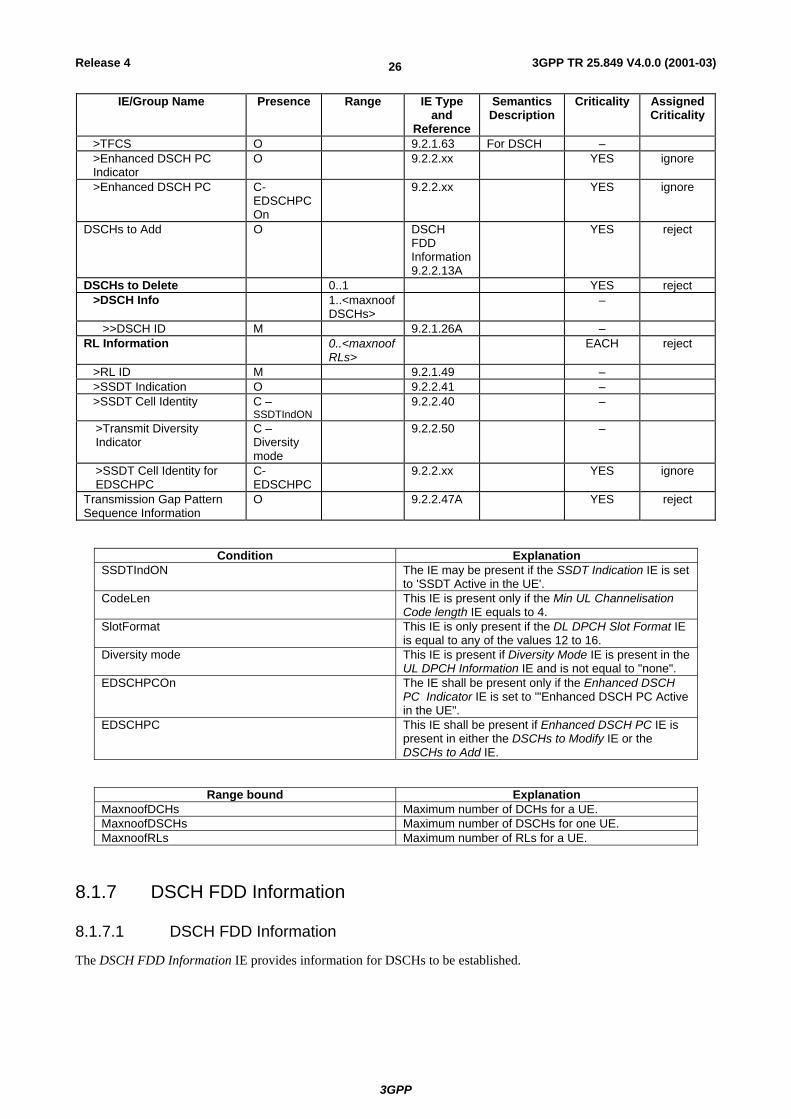
8.1.7 DSCH FDD Information
8.1.7.1 DSCH FDD Information
The DSCH FDD Information IE provides information for DSCHs to be established.

3GPP
3GPP TR 25.849 V4.0.0 (2001-03)27Release 4
IE/Group Name Presence Range IE type and
reference
Semantics description
Criticality Assigned Criticality
DSCH FDD Information 1 – >DSCH Specific FDD Information
1..<maxnoofDSCHs>
–
>>DSCH ID M 9.2.1.26A – >>TrCh Source Statistics Descriptor
M 9.2.1.65 –
>>Transport Format Set
M 9.2.1.64 For DSCH –
>>Allocation/Retention Priority
M 9.2.1.1 –
>>Scheduling Priority Indicator
M 9.2.1.51A –
>>BLER M 9.2.1.4 – >PDSCH RL ID M RL ID
9.2.1.49 –
>TFCS M 9.2.1.63 For DSCH – >Enhanced DSCH PC O 9.2.2.xx YES ignore
Range bound Explanation MaxnoofDSCHs Maximum number of DSCHs for one UE.
8.1.8 NEW IEs To support DSCH power control enhancement during soft handover function, following new IEs shall be defined.
8.1.8.1 Enhanced DSCH PC
The Enhanced DSCH PC includes all the parameters which are needed for DSCH power control improvement during soft handover.
IE/Group Name Presence Range IE type and reference
Semantics description
Enhanced DSCH PC Wnd M 9.2.2.xx Enhanced DSCH PC Counter M 9.2.2.xx Enhanced DSCH Power Offset M 9.2.2.xx
8.1.8.2 Enhanced DSCH PC Counter
The Enhanced DSCH PC Counter parameter gives the number of correct cell ID command to receive in the averaging window, Enhance DSCH PC Wnd IE.
IE/Group Name Presence Range IE type and reference
Semantics description
Enhanced DSCH PC Counter
INTEGER(1..50)
8.1.8.3 Enhanced DSCH PC Indicator
The Enhanced DSCH PC Indicator indicates whether Enhanced DSCH PC is in use by the UE or not.

3GPP
3GPP TR 25.849 V4.0.0 (2001-03)28Release 4
IE/Group Name Presence Range IE type and reference
Semantics description
Enhanced DSCH PC Indicator ENUMERATED(Enhanced DSCH PC Active in the UE, Enhanced DSCH PC not Active in the UE)
8.1.8.4 Enhanced DSCH PC Wnd
The Enhanced DSCH PC Wnd parameter shows the window size to decide primary or non-primary cell.
IE/Group Name Presence Range IE type and reference
Semantics description
Enhanced DSCH PC Wnd INTEGER(1..10)
8.1.8.5 Enhanced DSCH Power Offset
The Enhanced DSCH Power Offset parameter gives the power offset to be added on DSCH when cell is decided to be primary.
IE/Group Name Presence Range IE type and reference
Semantics description
Enhanced DSCH Power Offset
INTEGER(-15..0)
step 1dB
8.1.8.6 SSDT Cell Identity for EDSCHPC
The SSDT Cell Identity for EDSCHPC is a temporary ID for enhanced DSCH power control.
IE/Group Name Presence Range IE type and reference
Semantics description
SSDT Cell Identity for EDSCHPC
SSDT Cell Identity 9.2.2.40
8.2 Impacts on NBAP (TS 25.433)
8.2.1 Radio Link Setup procedure Void.
8.2.2 Radio Link Setup
8.2.2.1 General
This procedure is used for establishing the necessary resources for a new Node B Communication Context in the Node B.

3GPP
3GPP TR 25.849 V4.0.0 (2001-03)29Release 4
8.2.2.2 Successful Operation
CRNC Node B
RADIO LINK SETUP REQUEST
RADIO LINK SETUP RESPONSE
Figure 7: Radio Link Setup procedure: Successful Operation
The procedure is initiated with a RADIO LINK SETUP REQUEST message sent from the CRNC to Node B.
Upon reception of RADIO LINK SETUP REQUEST message, the Node B shall reserve necessary resources and configure the new Radio Link(s) according to the parameters given in the message.
[FDD – The RL Setup procedure can be used to setup one or more radio links. The procedure shall include the establishment of one or more DCHs on all radio links, and in addition, it can include the establishment of one or more DSCHs on one radio link.]
[TDD – The RL Setup procedure is used for setup of one radio link including one or more transport channels. The transport channels can be a mix of DCHs, DSCHs, and USCHs, including also combinations where one or more transport channel types are not present.]
[FDD - The First RLS Indicator IE indicates if the concerning RL shall be considered part of the first RLS established towards this UE. If the First RLS indicator IE is set to "first RLS", the Node B shall use a TPC pattern of n* "01" + "1" in the DL of the concerning RL and all RLs which are part of the same RLS, until UL synchronisation is achieved on the Uu. The parameter n shall be set equal to the value received in the DL TPC pattern 01 count IE in the Cell Setup procedure. The TPC pattern shall continuously be repeated but shall be restarted at the beginning of every frame with CFNmod4=0. For all other RLs, the Node B shall use a TPC pattern of all "1"'s in the DL until UL synchronisation is achieved on the Uu.]
[FDD - The Diversity Control Field IE indicates for each RL (except the first RL in the message) whether the Node B shall combine the concerned RL or not. If the Diversity Control Field IE indicates, "may be combined with already existing RLs", then Node B shall decide for either of the alternatives. If the Diversity Control Field IE is set to "Must", the Node B shall combine the RL with one of the other RL. Diversity combining is applied to Dedicated Transport Channels (DCH), i.e. it is not applied to the DSCHs. When a new RL is to be combined, the Node B shall choose which RL(s) to combine it with.]
[FDD – If the received Limited Power Increase IE is set to 'Used', the DRNS shall, if supported, use Limited Power Increase according to ref. [10] clause 5.2.1 for the inner loop DL power control.]
[FDD – If the received Inner Loop DL PC Status IE is set to "Active", the Node B shall activate the inner loop DL power control for all RLs. If Inner Loop DL PC Status IE is set to "Inactive", the Node B shall deactivate the inner loop DL power control for all RLs according to ref. [10]]
[TDD -If the DCH Information IE is present, the Node B shall configure the new DCH(s) according to the parameters given in the message.]
If the RADIO LINK SETUP REQUEST message includes a DCH Info IE with multiple DCH Specific Info IEs then, the Node B shall treat the DCHs in the DCH Info IE as a set of co-ordinated DCHs. The Node B shall include these DCHs in the new configuration only if it can include all of them in the new configuration.
[FDD – When more than one DL DPDCH are assigned per RL, the segmented physical channel shall be mapped on to DL DPDCHs according to [8]. When p number of DL DPDCHs are assigned to each RL, the first pair of DL Scrambling Code and FDD DL Channelisation Code Number corresponds to "PhCH number 1", the second to "PhCH number 2", and so on until the pth to "PhCH number p".]

3GPP
3GPP TR 25.849 V4.0.0 (2001-03)30Release 4
[FDD - For DCHs which do not belong to a set of co-ordinated DCHs with the QE-Selector IE set to "selected", the Transport channel BER from that DCH shall be the base for the QE in the UL data frames. If no Transport channel BER is available for the selected DCH the Physical channel BER shall be used for the QE, ref. [16]. If the QE-Selector is set to "non-selected", the Physical channel BER shall be used for the QE in the UL data frames, ref. [16].]
For a set of co-ordinated DCHs the Transport channel BER from the DCH with the QE-Selector IE set to "selected" shall be used for the QE in the UL data frames, ref. [16]. [FDD - If no Transport channel BER is available for the selected DCH the Physical channel BER shall be used for the QE, ref. [16]. If all DCHs have QE-Selector IE set to "non-selected" the Physical channel BER shall be used for the QE, ref. [16]].
The Node B shall prioritise resource allocation for the RL(s) to be established according to Annex A.
The received Frame Handling Priority IE specified for each Transport Channel should be used when prioritising between different frames in the downlink on the radio interface in congestion situations within the Node B once the new RL(s) has been activated.
The Node B shall use the included UL FP Mode IE for a DCH or a set of co-ordinated DCHs to be added as the new FP Mode in the Uplink of the user plane for the DCH or the set of co-ordinated DCHs in the new configuration.
The Node B shall use the included ToAWS IE for a DCH or a set of co-ordinated DCHs to be added as the new Time of Arrival Window Start Point in the user plane for the DCH or the set of co-ordinated DCHs in the new configuration.
The Node B shall use the included ToAWE IE for a DCH or a set of co-ordinated DCHs to be added as the new Time of Arrival Window End Point in the user plane for the DCH or the set of co-ordinated DCHs in the new configuration.
[FDD - If the Propagation Delay IE is included, the Node B may use this information to speed up the detection of L1 synchronisation.]
[FDD - The UL SIR Target IE included in the message shall be used by the Node B as initial UL SIR target for the UL inner loop power control.]
[FDD - The Node B shall start the DL transmission using the initial DL power specified in the message on each DL channelisation code of the RL until either UL synchronisation is achieved for the RLS or a DL POWER CONTROL REQUEST message is received. No inner loop power control or balancing shall be performed during this period. The DL power shall then vary according to the inner loop power control (see ref.[10], clause 5.2.1.2) with DPC MODE=0 and the power control procedure (see clause 8.3.7), but shall always be kept within the maximum and minimum limit specified in the RL SETUP REQUEST message.].
[TDD - The Node B shall start the DL transmission using the initial DL power specified in the message on each DL channelisation code and on each Time Slot of the RL until the UL synchronisation is achieved for the RL. No inner loop power control shall be performed during this period. The DL power shall then vary according to the inner loop power control (see ref. [22], clause 4.2.3.3), but shall always be kept within the maximum and minimum limit specified in the RL SETUP REQUEST message.].
If the DSCH Information IE Group is present, the Node B shall configure the new DSCH(s) according to the parameters given in the message.
[FDD - If the RADIO LINK SETUP REQUEST message includes the SSDT Cell Identity IE, the Node B shall activate SSDT, if supported, using the SSDT Cell Identity IE and SSDT Cell Identity Length IE.]
[FDD - If the RADIO LINK SETUP REQUEST message includes the SSDT Cell Identity for EDSCHPC IE, the Node B shall activate enhanced DSCH power control, if supported, using the SSDT Cell Identity for EDSCHPC IE and SSDT Cell Identity Length IE as well as Enhanced DSCH PC IE. If the RADIO LINK SETUP REQUEST message includes both SSDT Cell Identity IE and SSDT Cell Identity for EDSCHPC IE, then Node B shall ignore the value in SSDT Cell Identity for EDSCHPC IE]
[FDD – If the RADIO LINK SETUP REQUEST message includes the TFCI2 Bearer Information IE then the Node B shall support the setup of a transport bearer on which the DSCH TFCI Signaling control frames shall be received. The Node B shall manage the time of arrival of these frames according to the values of ToAWS and ToAWE specified in the IE's. The Binding ID IE and Transport Layer Address IE for the new bearer to be set up for this purpose shall be returned in the RADIO LINK SETUP RESPONSE message.]
[FDD - If the TFCI Signalling Mode IE within the RADIO LINK SETUP message indicates that there shall be a hard split on the TFCI field but the TFCI2 Bearer Information IE is not included in the message then the Node B shall transmit the TFCI2 field with zero power.]

3GPP
3GPP TR 25.849 V4.0.0 (2001-03)31Release 4
[FDD - If the TFCI Signalling Mode IE within the RADIO LINK SETUP message indicates that there shall be a hard split on the TFCI and the TFCI2 Bearer Information IE is included in the message then the Node B shall transmit the TFCI2 field with zero power until Synchronization is achieved on the TFCI2 transport bearer and the first valid DSCH TFCI Signalling control frame is received on this bearer (see ref. [24]).]
[FDD - If the RADIO LINK SETUP REQUEST message contains an SSDT Cell Identity IE the Node B shall activate SSDT, if supported, for the concerned new RL, with the indicated cell identity used for that RL.]
[FDD - If the RADIO LINK SETUP REQUEST message includes the Transmission Gap Pattern Sequence Information IE, the Node B shall store the information about the Transmission Gap Pattern Sequences to be used in the Compressed Mode Configuration. This Compressed Mode Configuration shall be valid in the Node B until the next Compressed Mode Configuration is configured in the Node B or Node B Communication Context is deleted.]
[FDD- If the Downlink compressed mode method in one or more Transmission Gap Pattern Sequence is set to 'SF/2' in the RADIO LINK SETUP REQUEST message, the Node B shall use or not the alternate scrambling code as indicated for each DL Channelisation Code in the Transmission Gap Pattern Sequence Code Information IE.]
[FDD - If the RADIO LINK SETUP REQUEST message includes the Transmission Gap Pattern Sequence Information IE and the Active Pattern Sequence Information IE, the Node B shall immediately activate the indicated Transmission Gap Pattern Sequences. For each sequence the TGCFN refers to the latest passed CFN with that value. If during the compressed mode measurement the gaps of two or more pattern sequences overlap, the Node B shall behave as specified in clause 8.3.12.]
[FDD – For each RL not having a common generation of the TPC commands in the DL with another RL, the Node B shall assign the RL Set ID IE included in the RADIO LINK SETUP RESPONSE message a value that uniquely identifies the RL Set within the Node B Communication context.]
[FDD – For all RLs having a common generation of the TPC commands in the DL with another RL, the Node B shall assign the RL Set ID IE included in the RADIO LINK SETUP RESPONSE message the same value. This value shall uniquely identify the RL Set within the Node B Communication context.]
[TDD -If the USCH Information IE is present, the Node B shall configure the new USCH(s) according to the parameters given in the message.]
[TDD – If the DL Timeslot ISCP IE is present, the Node B shall use the indicated value when deciding the initial DL TX Power for each timeslot as specified in [21], i.e. it shall reduce the DL TX power in those downlink timeslots of the radio link where the interference is low, and increase the DL TX power in those timeslots where the interference is high, while keeping the total downlink power in the radio link unchanged].
If the RLs are successfully setup, the Node B shall start reception on the new RL(s) and respond with a RADIO LINK SETUP RESPONSE message.
[FDD - The Node B shall indicate with the Diversity Indication IE whether the RL is combined or not. In case of combining, only the Reference RL ID IE shall be included to indicate one of the existing RLs that the concerned RL is combined with. In case of not combining the Node B shall include in the RL SETUP RESPONSE the Binding ID IE and Transport Layer Address IE for the transport bearer to be established for each DCH of this RL.]
[TDD – The Node B shall include in the RADIO LINK SETUP RESPONSE the Binding ID IE and Transport Layer Address IE for the transport bearer to be established for each DCH of this RL.]
The Node B shall include in the RADIO LINK SETUP RESPONSE the Binding ID IE and Transport Layer Address IE for the transport bearer to be established for each DSCH of this RL.
[TDD – In case the USCH Information IE is present, the Node B shall include in the RADIO LINK SETUP RESPONSE the Binding ID IE and Transport Layer Address IE for the transport bearer to be established for each USCH of this RL.]
In case of coordinated DCH, the Binding ID IE and the Transport Layer Address IE shall be specify for only one of the coordinated DCHs.
After sending of the RADIO LINK SETUP RESPONSE message the Node B shall continuously attempt to obtain UL synchronisation and start reception on the new RL. The Node B shall start transmission on the new RL after synchronisation is achieved in the DL user plane as specified in [16].

3GPP
3GPP TR 25.849 V4.0.0 (2001-03)32Release 4
[FDD – When Diversity Mode IE is "STTD", "Closedloop mode1", or "Closedloop mode2", the DRNC shall activate/deactivate the Transmit Diversity to each Radio Link in accordance with Transmit Diversity Indication IE]
[FDD - If the RADIO LINK SETUP REQUEST message includes the SSDT Cell Identity IE, the Node B may activate SSDT using the SSDT Cell Identity IE and SSDT Cell Identity Length IE.]
[FDD - Irrespective of SSDT activation, the Node B shall include in the RADIO LINK SETUP RESPONSE message an indication concerning the capability to support SSDT on this RL. Only if the RADIO LINK SETUP REQUEST message requested SSDT activation and the RADIO LINK SETUP RESPONSE message indicates that the SSDT capability is supported for this RL, SSDT is activated in the Node B.]
[FDD –The UL out-of-sync algorithm defined in [10] shall for each of the established RL Set(s) use the maximum value of the parameters N_OUTSYNC_IND and T_RLFAILURE, and the minimum value of the parameters N_INSYNC_IND, that are configured in the cells supporting the radio links of the RL Set].
8.2.3 Synchronised Radio Link Reconfiguration Preparation procedure Void.
8.2.4 Synchronised Radio Link Reconfiguration Preparation
8.2.4.1 General
The Synchronised Radio Link Reconfiguration Preparation procedure is used to prepare a new configuration of all Radio Links related to one UE-UTRAN connection within a Node B.
The Synchronised Radio Link Reconfiguration Preparation procedure shall not be initiated if a Prepared Reconfiguration exists, as defined in clause 3.1.
8.2.4.2 Successful Operation
CRNC Node B
RADIO LINK RECONFIGURATION PREPARE
RADIO LINK RECONFIGURATION READY
Figure 8: Synchronised Radio Link Reconfiguration Preparation procedure, Successful Operation
The Synchronised Radio Link Reconfiguration Preparation procedure is initiated by the CRNC by sending the message RADIO LINK RECONFIGURATION PREPARE to the Node B. The message shall use the Communication Control Port assigned for this Node B Communication Context.
Upon reception, the Node B shall reserve necessary resources for the new configuration of the Radio Link(s) according to the parameters given in the message. Unless specified below, the meaning of parameters is specified in other specifications.
The Node B shall prioritise resource allocation for the RL(s) to be modified according to Annex A.

3GPP
3GPP TR 25.849 V4.0.0 (2001-03)33Release 4
DCH Modification:
If the RADIO LINK RECONFIGURATION PREPARE message includes any DCHs to Modify IEs then the Node B shall treat them each as follows:
- If the DCHs to Modify IE includes the Frame Handling Priority IE, the Node B should store this information for this DCH in the new configuration. The received Frame Handling Priority should be used when prioritising between different frames in the downlink on the radio interface in congestion situations within the Node B once the new configuration has been activated.
- If the DCHs to Modify IE includes the Transport Format Set IE for the UL of a DCH, the Node B shall apply the new Transport Format Set in the Uplink of this DCH in the new configuration.
- If the DCHs to Modify IE includes the Transport Format Set IE for the DL of a DCH, the Node B shall apply the new Transport Format Set in the Downlink of this DCH in the new configuration.
- If the DCHs to Modify IE includes multiple DCH Specific Info IEs then the Node B shall treat the DCHs in the DCHs to Modify IE as a set of co-ordinated DCHs. The Node B shall include these DCHs in the new configuration only if it can include all of them in the new configuration.
- If the DCHs to Modify IE includes the UL FP Mode IE for a DCH or a DCH which belongs to a set of co-ordinated DCHs, the Node B shall apply the new FP Mode in the Uplink of the user plane for the DCH or the set of co-ordinated DCHs in the new configuration.
- If the DCHs to Modify IE includes the ToAWS IE for a DCH or a DCH which belongs to a set of co-ordinated DCHs, the Node B shall apply the new ToAWS in the user plane for the DCH or the set of co-ordinated DCHs in the new configuration.
- If the DCHs to Modify IE includes the ToAWE IE for a DCH or a DCH which belongs to a set of co-ordinated DCHs, the Node B shall apply the new ToAWE in the user plane for the DCH or the set of co-ordinated DCHs in the new configuration.
- [TDD – If the DCHs to Modify IE includes the CCTrCH ID IE for the DL of a DCH to be modified, the Node B shall apply the new CCTrCH ID in the Downlink of this DCH in the new configuration.]
- [TDD - If the DCHs to Modify IE includes the CCTrCH ID IE for the UL of a DCH to be modified, the Node B shall apply the new CCTrCH ID in the Uplink of this DCH in the new configuration.]
DCH Addition:
If the RADIO LINK RECONFIGURATION PREPARE message includes any DCHs to Add IEs then the Node B shall treat them each as follows:
- If the DCHs to Add IE multiple DCH specific Info IEs then, the Node B shall treat the DCHs in the DCHs to Add IE as a set of co-ordinated DCHs. The Node B shall include these DCHs in the new configuration only if it can include all of them in the new configuration.
- [FDD - For DCHs which do not belong to a set of co-ordinated DCHs with the QE-Selector IE set to "selected", the Transport channel BER from that DCH shall be the base for the QE in the UL data frames. If no Transport channel BER is available for the selected DCH the Physical channel BER shall be used for the QE, ref. [16]. If the QE-Selector is set to "non-selected", the Physical channel BER shall be used for the QE in the UL data frames, ref. [16]].
For a set of co-ordinated DCHs the Transport channel BER from the DCH with the QE-Selector IE set to "selected" shall be used for the QE in the UL data frames, ref. [16]. [FDD - If no Transport channel BER is available for the selected DCH the Physical channel BER shall be used for the QE, ref. [16]. If all DCHs have QE-Selector IE set to "non-selected" the Physical channel BER shall be used for the QE, ref. [16]].
The Node B should store the Frame Handling Priority IE received for a DCH to be added in the new configuration. The received Frame Handling Priority should be used when prioritising between different frames in the downlink on the radio interface in congestion situations within the Node B once the new configuration has been activated.
The Node B shall use the included UL FP Mode IE for a DCH or a set of co-ordinated DCHs to be added as the new FP Mode in the Uplink of the user plane for the DCH or the set of co-ordinated DCHS in the new configuration.
3GPP
3GPP TR 25.849 V4.0.0 (2001-03)34Release 4
The Node B shall use the included ToAWS IE for a DCH or a set of co-ordinated DCHs to be added as the new Time of Arrival Window Start Point in the user plane for the DCH or the set of co-ordinated DCHs in the new configuration.
The Node B shall use the included ToAWE IE for a DCH or a set of co-ordinated DCHs to be added as the new Time of Arrival Window End Point in the user plane for the DCH or the set of co-ordinated DCHs in the new configuration.
[TDD – The Node B shall apply the CCTrCH ID IE (for the DL) in the Downlink of this DCH in the new configuration.]
[TDD – The Node B shall apply the CCTrCH ID IE (for the UL) in the Uplink of this DCH in the new configuration.]
DCH Deletion:
If the RADIO LINK RECONFIGURATION PREPARE message includes any DCHs to Delete IEs, the Node B shall not include the referenced DCHs in the new configuration.
If all of the DCHs belonging to a set of coordinated DCHs are requested to be deleted, the Node B shall not include this set of coordinated DCHs in the new configuration.
Physical Channel Modification:
[FDD - If the RADIO LINK RECONFIGURATION PREPARE message includes an UL DPCH Information IE then the Node B shall apply the parameters to the new configuration as follows: ]
- [FDD - If the UL DPCH Information IE includes the Uplink Scrambling Code IE, the Node B shall apply this Uplink Scrambling Code to the new configuration.]
- [FDD – If the UL DPCH Information IE includes the Min UL Channelisation Code Length IE, the Node B shall apply the value in the new configuration. The Node B shall apply the contents of the Max Number of UL DPDCHs IE (if it is included) in the new configuration.]
- [FDD – If the UL DPCH Information IE includes the UL SIR Target IE, the Node B shall use the value for the UL inner loop power control when the new configuration is being used.]
- [FDD – If the UL DPCH Information IE includes the Puncture Limit IE, the Node B shall apply the value in the uplink of the new configuration
- [FDD - The Node B shall use the TFCS IE for the UL (if present) when reserving resources for the uplink of the new configuration. The Node B shall apply the new TFCS in the Uplink of the new configuration.]
- [FDD - If the UL DPCH Information IE includes the UL DPCCH Slot Format IE, group the Node B shall set the new Uplink DPCCH Structure to the new configuration.]
- [FDD - If the UL DPCH Information IE includes the Diversity Mode IE, the Node B shall apply diversity according to the given value.]
- [FDD – If the UL DPCH Information IE includes an SSDT Cell Identity Length IE and/or an S-Field Length IE, the Node B shall apply the values in the new configuration.]
[FDD - If the RADIO LINK RECONFIGURATION PREPARE message includes a DL DPCH Information IE then the Node B shall apply the parameters to the new configuration as follows:]
- [FDD - The Node B shall use the TFCS IE for the DL (if it is present) when reserving resources for the downlink of the new configuration. The Node B shall apply the new TFCS in the Downlink of the new configuration.]
- [FDD – If the DL DPCH Information IE includes the TFCI Signalling Mode IE or the TFCI Presence IE, the Node B shall use the information when building TFCIs in the new configuration.]
- [FDD - If the DL DPCH Information IE includes the DL DPCCH Slot Format IE, group the Node B shall set the new Downlink DPCCH Structure to the new configuration.]
- [FDD – If the DL DPCH Information IE includes the Multiplexing Position IE, the Node B shall apply the indicated multiplexing type in the new configuration.]
3GPP
3GPP TR 25.849 V4.0.0 (2001-03)35Release 4
- [FDD – If the DL DPCH Information IE includes the Limited Power Increase IE and the IE is set to 'Used', the Node B shall use Limited Power Increase ref. [10] clause 5.2.1 for the inner loop DL power control in the new configuration.]
- [FDD – If the DL DPCH Information IE includes the Limited Power Increase IE and the IE is set to 'Not Used', the Node B shall not use Limited Power Increase for the inner loop DL power control in the new configuration.]
- [FDD - If the DL DPCH Information IE includes the PDSCH code mapping IE then the Node B shall apply the defined mapping between TFCI values and PDSCH channelisation codes.]
- [FDD - If the DL DPCH Information IE includes the PDSCH RL ID IE then the Node B shall infer that the PDSCH for the specified user will be transmitted on the defined radio link.]
[FDD - If the RADIO LINK RECONFIGURATION PREPARE message includes the Transmission Gap Pattern Sequence Information IE the Node B shall store the new information about the Transmission Gap Pattern Sequences to be used in the new Compressed Mode Configuration. This new Compressed Mode Configuration shall be valid in the Node B until the next Compressed Mode Configuration is configured in the Node B or Node B Communication Context is deleted.]
[TDD - UL/DL CCTrCH Modification]
[TDD - If the RADIO LINK RECONFIGURATION PREPARE message includes any UL CCTrCH to Modify or DL CCTrCH to Modify IEs, then the Node B shall treat them each as follows:]
- [TDD - If the IE includes any of TFCS IE, TFCI coding IE or Puncture Limit IE the Node B shall apply these as the new values, otherwise the old values specified for this CCTrCH are still applicable.]
- [TDD – If the IE includes any UL DPCH to add or DL DPCH to add IEs, the Node B shall include this DPCH in the new configuration.]
- [TDD – If the IE includes any UL DPCH to delete or DL DPCH to delete IEs, the Node B shall remove this DPCH in the new configuration.]
- [TDD – If the IE includes any UL DPCH to modify or DL DPCH to modify IEs, and includes any of Repetition Period IE, Repetition Length IE, or TDD DPCH Offset IE or the message includes UL/DL Timeslot Information and includes any of Midamble shift and Burst Type IE, Time Slot IE, or TFCI presence IE or the message includes UL/DL Code information and includes TDD Channelisation Code IE, the Node B shall apply these specified information elements as the new values, otherwise the old values specified for this DPCH configuration are still applicable.]
[TDD – UL/DL CCTrCH Addition]
[TDD -If the RADIO LINK RECONFIGURATION PREPARE message includes any UL CCTrCH to Add IE or DL CCTrCH to Add IE, the Node B shall include this CCTrCH in the new configuration.]
[TDD - If the UL/DL CCTrCH to Add IE includes any UL/DL DPCH Information IE, the Node B shall reserve necessary resources for the new configuration of the UL/DL DPCH(s) according to the parameters given in the message.]
[TDD – UL/DL CCTrCH Deletion]
[TDD - If the RADIO LINK RECONFIGURATION PREPARE message includes any UL or DL CCTrCH to be deleted, the Node B shall remove this CCTrCH in the new configuration.]
DSCH Addition/Modification/Deletion:
If the RADIO LINK RECONFIGURATION PREPARE message includes any DSCH to modify, DSCH to add or DSCH to delete IEs, then the Node B shall use this information to add/modify/delete the indicated DSCH channels to/from the radio link, in the same way as the DCH info is used to add/modify/release DCHs.
The Node B shall include in the RADIO LINK RECONFIGURATION READY message both the Transport Layer Address IE and the Binding ID IE for the transport bearer to be established for each DSCH.
3GPP
3GPP TR 25.849 V4.0.0 (2001-03)36Release 4
[FDD – If the RADIO LINK RECONFIGURATION PREPARE message includes the TFCI2 Bearer Information IE then the Node B shall support the setup of a transport bearer on which the DSCH TFCI Signaling control frames shall be received if one does not already exist or shall apply the new values if such a bearer does already exist. The Binding ID IE and Transport Layer Address IE of any new bearer to be set up for this purpose shall be returned in the RADIO LINK RECONFIGURATION READY message. If the RADIO LINK RECONFIGURATION PREPARE message specifies that the TFCI2 transport bearer is to be deleted then the Node B shall release the resources associated with that bearer in the new configuration.
[FDD - If the TFCI Signalling Mode IE within the RADIO LINK RECONFIGURATION PREPARE message indicates that there shall be a hard split on the TFCI field but a TFCI2 transport bearer has not already been set up and TFCI2 Bearer Information IE is not included in the message then the Node B shall transmit the TFCI2 field with zero power in the new configuration.]
[FDD - If the TFCI Signalling Mode IE within the RADIO LINK RECONFUGURATION PREPARE message indicates that there shall be a hard split on the TFCI and the TFCI2 Bearer Information IE is included in the message then the Node B shall transmit the TFCI2 field with zero power until Synchronization is achieved on the TFCI2 transport bearer and the first valid DSCH TFCI Signalling control frame is received on this bearer in the new configuration (see ref.[24]).]
[FDD - If the RADIO LINK RECONFIGURATION PREPARE message includes the DSCH Common Information IE, the Node B shall treat it as follows:]
- [FDD - If the Enhanced DSCH PC Indicator IE is included and set to "Enhanced DSCH PC Active in the UE ", the Node B shall activate enhanced DSCH power control, if supported, using either:]
- [FDD - the SSDT Cell Identity for EDSCHPC IE in the RL Information IE, if the SSDT Cell Identity IE is not included in the RL Information IE or]
- [FDD - the SSDT Cell Identity IE in the RL Information IE, if both the SSDT Cell Identity IE and the SSDT Cell Identity for EDSCHPC IE are included in the RL Information IE.]
- [FDD - together with the SSDT Cell Identity Length IE in UL DPCH Information IE, and Enhanced DSCH PC IE, in the new configuration.]
[FDD - If the RADIO LINK RECONFIGURATION PREPARE message includes the Enhanced DSCH PC Indicator IE set to "Enhanced DSCH PC not Active in the UE", the Node B shall deactivate enhanced DSCH power control in the new configuration.]
[TDD - USCH Addition/Modification/Deletion:]
- [TDD - If the RADIO LINK RECONFIGURATION PREPARE message includes USCH information for the USCHs to be added/modified/deleted then the Node B shall use this information to add/modify/delete the indicated USCH channels to/from the radio link, in the same way as the DCH info is used to add/modify/release DCHs.]
- [TDD - The Node B shall include in the RADIO LINK RECONFIGURATION READY message both the Transport Layer Address IE and the Binding ID IE for the transport bearer to be established for each USCH.]
RL Information:
If the RADIO LINK RECONFIGURATION PREPARE message includes the RL Information IE, the Node B shall treat it as follows:
- [FDD – When more than one DL DPDCH are assigned per RL, the segmented physical channel shall be mapped on to DL DPDCHs according to [8]. When p number of DL DPDCHs are assigned to each RL, the first pair of DL Scrambling Code and FDD DL Channelisation Code Number corresponds to "PhCH number 1", the second to "PhCH number 2", and so on until the pth to "PhCH number p".]
- [FDD - If the RL Information IE includes the SSDT Indication IE set to "SSDT Active in the UE", the Node B may activate SSDT using the SSDT Cell Identity IE in the new configuration.]
- [FDD - If the RL Information IE includes the SSDT Indication IE set to "SSDT not Active in the UE", the Node B shall deactivate SSDT in the new configuration.]
3GPP
3GPP TR 25.849 V4.0.0 (2001-03)37Release 4
- [FDD - If the RL Information IE includes both SSDT Cell Identity IE and SSDT Cell Identity for EDSCHPC IE, then Node B shall ignore the SSDT Cell Identity for EDSCHPC IE.]
- [FDD – If the RL Information IE includes a DL Code Information IE containing a DL Scrambling Code IE, the Node B shall apply the scrambling code in the new configuration.]
- [FDD – If the RL Information IE includes the DL Code Information IE containing a DL Channelisation Code Number IE, the Node B shall apply the channelisation code in the new configuration.]
- [FDD- If the RL Information IE contains the Transmission Gap Pattern Sequence Code Information IE for any of the allocated DL Channelisation code, the Node B shall apply the alternate scrambling code as indicated whenever the downlink compressed mode method SF/2 is active in the new configuration.]
- If the RL Information IE includes the Maximum DL Power and/or the Minimum DL Power IEs, the Node B shall apply the values in the new configuration.
General
If the requested modifications are allowed by the Node B and the Node B has successfully reserved the required resources for the new configuration of the Radio Link(s), it shall respond to the CRNC with the RADIO LINK RECONFIGURATION READY message. When this procedure has been completed successfully there exist a Prepared Reconfiguration, as defined in clause 3.1.
In the RADIO LINK RECONFIGURATION READY message, the Node B shall include the RL Information Response IE for each affected Radio Link.
The Node B shall include in the RADIO LINK RECONFIGURATION READY message the Transport Layer Address and the Binding ID for any Transport Channel being added, or any Transport Channel being modified for which a new transport bearer was requested with the Transport Bearer Request Indicator IE.
In case of a DCH requiring a new transport bearer on Iur, the Transport Layer Address IE and the Binding ID shall be included in the IE DCH Information Response IE group.
In case of a set of coordinated DCHs requiring a new transport bearer on Iub, the Transport Layer Address IE and the Binding ID IE in the DCH Information Response IE group shall be included only for one of the DCH in the set of coordinated DCHs.
In case of a Radio Link being combined with another Radio Link within the Node B,the RL Information Response IE group shall be included only for one of the combined RLs. The Transport Layer Address IE and the Binding ID IE in the DCH Information Response IE group shall be included only for one of the combined Radio Links.
8.2.5 RADIO LINK SETUP REQUEST message To initiate DSCH power control improvement function during soft handover, SSDT Cell Identity for EDSCHPC, Enhanced DSCH PC Wnd, Enhanced DSCH PC Counter, and Enhanced DSCH Power Offset Ies shall be included in the RADIO LINK SETUP REQUEST message.

3GPP
3GPP TR 25.849 V4.0.0 (2001-03)38Release 4
8.2.6 RADIO LINK SETUP REQUEST 8.2.6.1 FDD message
IE/Group Name Presence Range IE type and
reference
Semantics description
Criticality Assigned Criticality
Message Discriminator M 9.2.1.45 – Message Type M 9.2.1.46 YES reject CRNC Communication Context ID
M 9.2.1.18 The reserved value "All CRNCCC" shall not be used.
YES reject
Transaction ID M 9.2.1.62 – UL DPCH Information 1 YES reject
>UL Scrambling Code M 9.2.2.59 – >Min UL Channelisation Code length
M 9.2.2.22 –
>Max Number of UL DPDCHs
C – CodeLen
9.2.2.21 –
>puncture Limit M 9.2.1.50 For UL – >TFCS M 9.2.1.58 for UL – >UL DPCCH Slot Format M 9.2.2.57 – > UL SIR Target M UL SIR
9.2.2.58 –
>Diversity mode M 9.2.2.9 – >SSDT cell ID Length O 9.2.2.45 – >S Field Length C-FBI 9.2.2.40 –
DL DPCH Information 1 YES reject >TFCS M 9.2.1.58 For DL – >DL DPCH Slot Format M 9.2.2.10 – >TFCI signalling mode M 9.2.2.50 – >TFCI presence C-
SlotFormat 9.2.1.57 –
>Multiplexing Position M 9.2.2.23 – >PDSCH RL ID C-DSCH RL ID
9.2.1.53 –
>PDSCH code mapping C-DSCH 9.2.2.25 – >Power Offset Information
1 –
>>PO1 M Power Offset 9.2.2.29
Power offset for the TFCI bits
–
>>PO2 M Power Offset 9.2.2.29
Power offset for the TPC bits
–
>>PO3 M Power Offset 9.2.2.29
Power offset for the pilot bits
_
>FDD TPC DL Step Size M 9.2.2.16 – >Limited Power Increase M 9.2.2.18A – >Inner Loop DL PC Status M 9.2.2.18B –
DCH Information M DCH FDD Information9.2.2.4D
YES reject
DSCH Information O DSCH FDD Information 9.2.2.13B
YES reject
TFCI2 bearer information 0..1 -
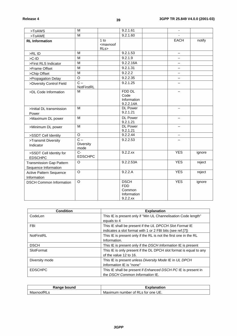
3GPP
3GPP TR 25.849 V4.0.0 (2001-03)39Release 4
>ToAWS M 9.2.1.61 - >ToAWE M 9.2.1.60 -
RL Information 1 to <maxnoofRLs>
EACH notify
>RL ID M 9.2.1.53 – >C-ID M 9.2.1.9 – >First RLS Indicator M 9.2.2.16A – >Frame Offset M 9.2.1.31 – >Chip Offset M 9.2.2.2 – >Propagation Delay O 9.2.2.35 – >Diversity Control Field C –
NotFirstRL 9.2.1.25 –
>DL Code Information M FDD DL Code Information 9.2.2.14A
–
>Initial DL transmission Power
M DL Power 9.2.1.21
–
>Maximum DL power M DL Power 9.2.1.21
–
>Minimum DL power M DL Power 9.2.1.21
–
>SSDT Cell Identity O 9.2.2.44 – >Transmit Diversity Indicator
C – Diversity mode
9.2.2.53 –
>SSDT Cell Identity for EDSCHPC
C-EDSCHPC
9.2.2.xx YES ignore
Transmission Gap Pattern Sequence Information
O 9.2.2.53A YES reject
Active Pattern Sequence Information
O 9.2.2.A YES reject
DSCH Common Information O DSCH FDD Common Information 9.2.2.xx
YES ignore
Condition Explanation CodeLen This IE is present only if "Min UL Channelisation Code length"
equals to 4 FBI This IE shall be present if the UL DPCCH Slot Format IE
indicates a slot format with 1 or 2 FBI bits (see ref.[7]) NotFirstRL This IE is present only if the RL is not the first one in the RL
Information. DSCH This IE is present only if the DSCH Information IE is present SlotFormat This IE is only present if the DL DPCH slot format is equal to any
of the value 12 to 16. Diversity mode This IE is present unless Diversity Mode IE in UL DPCH
Information IE is "none" EDSCHPC This IE shall be present if Enhanced DSCH PC IE is present in
the DSCH Common Information IE.
Range bound Explanation MaxnoofRLs Maximum number of RLs for one UE.

3GPP
3GPP TR 25.849 V4.0.0 (2001-03)40Release 4
8.2.7 RADIO LINK RECONFIGURATION PREPARE message To initiate or to terminate DSCH power control improvement function during soft handover, ,SSDT Cell Identity for EDSCHPC, Enhanced DSCH PC Indicator, Enhanced DSCH PC Wnd, Enhanced DSCH PC Counter, and Enhanced DSCH Power Offset IEs shall be included in the RADIO LINK RECONFIGURATION PREPARE message. Enhanced DSCH PC Wnd, Enhanced DSCH PC Counter, and Enhanced DSCH Power Offset IEs are conditional based on the value of Enhanced DSCH PC Indicator IE.
8.2.8 RADIO LINK RECONFIGURATION PREPARE 8.2.8.1 FDD Message
IE/Group Name Presence Range IE Type and
Reference
Semantic Description
Criticality Assigned Criticality
Message Discriminator M 9.2.1.45 – Message Type M 9.2.1.46 YES reject Node B Communication Context ID
M 9.2.1.48 The reserved value "All NBCC" shall not be used.
YES reject
Transaction ID M 9.2.1.62 – UL DPCH Information 0..1 YES reject
>UL Scrambling code O 9.2.2.59 – >UL SIR Target O UL SIR
9.2.2.58 –
>Min UL Channelistion Code Length
O 9.2.2.22 –
>Max Number of UL DPDCHs C – CodeLen
9.2.2.20 –
>Puncture Limit O 9.2.1.50 For UL – >TFCS O 9.2.1.58 – >UL DPCCH Slot Format O 9.2.2.57 – >Diversity mode O 9.2.2.9 – >SSDT Cell Identity Length O 9.2.2.45 – >S-Field Length O 9.2.2.40 –
DL DPCH Information 0..1 YES reject >TFCS O 9.2.1.58 – >DL DPCH Slot Format O 9.2.2.10 – >TFCI Signalling Mode O 9.2.2.50 – >TFCI presence C-Slot
Format 9.2.1.57 –
>Multiplexing Position O 9.2.2.23 – >PDSCH code mapping O 9.2.2.25 – >PDSCH RL ID O RL ID
9.2.1.53 –
>Limited Power Increase O 9.2.2.18A – DCHs to Modify O DCHs FDD
to Modify 9.2.2.4E
YES reject
DCHs to Add O DCH FDD Information 9.2.2.4D
YES reject
DCHs to Delete 0..<maxnoofDCHs>
GLOBAL reject
>DCH ID M 9.2.1.20 – DSCH to modify 0..<max
noofDS YES reject
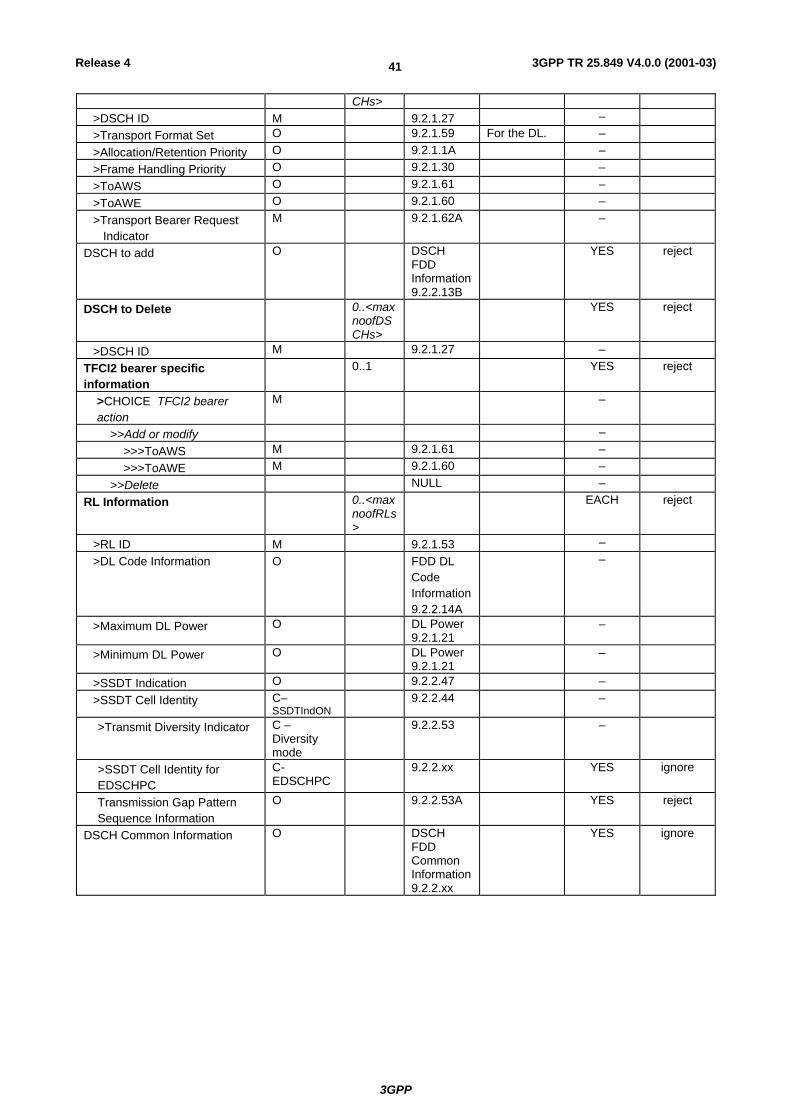
3GPP
3GPP TR 25.849 V4.0.0 (2001-03)41Release 4
CHs> >DSCH ID M 9.2.1.27 – >Transport Format Set O 9.2.1.59 For the DL. – >Allocation/Retention Priority O 9.2.1.1A – >Frame Handling Priority O 9.2.1.30 – >ToAWS O 9.2.1.61 – >ToAWE O 9.2.1.60 – >Transport Bearer Request Indicator
M 9.2.1.62A –
DSCH to add O DSCH FDD Information 9.2.2.13B
YES reject
DSCH to Delete 0..<maxnoofDSCHs>
YES reject
>DSCH ID M 9.2.1.27 – TFCI2 bearer specific information
0..1 YES reject
>CHOICE TFCI2 bearer action
M –
>>Add or modify – >>>ToAWS M 9.2.1.61 – >>>ToAWE M 9.2.1.60 –
>>Delete NULL – RL Information 0..<max
noofRLs>
EACH reject
>RL ID M 9.2.1.53 – >DL Code Information O FDD DL
Code Information 9.2.2.14A
–
>Maximum DL Power O DL Power 9.2.1.21
–
>Minimum DL Power O DL Power 9.2.1.21
–
>SSDT Indication O 9.2.2.47 – >SSDT Cell Identity C–
SSDTIndON 9.2.2.44 –
>Transmit Diversity Indicator C – Diversity mode
9.2.2.53 –
>SSDT Cell Identity for EDSCHPC
C-EDSCHPC
9.2.2.xx YES ignore
Transmission Gap Pattern Sequence Information
O 9.2.2.53A YES reject
DSCH Common Information O DSCH FDD Common Information 9.2.2.xx
YES ignore

3GPP
3GPP TR 25.849 V4.0.0 (2001-03)42Release 4
Condition Explanation SSDTIndON The IE may be present if the SSDT Indication is set to
'SSDT Active in the UE'. CodeLen This IE is present only if "Min UL Channelisation Code
length" equals to 4. SlotFormat This IE is only present if the DL DPCH slot format is
equal to any of the value 12 to 16. SF/2 This IE is present only if the Transmission Gap
Pattern Sequence Information IE is included and the indicated Downlink Compressed Mode method for at least one of the included Transmission Gap Pattern Sequence is set to "SF/2'".
Diversity mode This IE is present unless Diversity Mode IE in UL DPCH Information group, unless it is equal to "none"
EDSCHPC This IE shall be present if Enhanced DSCH PC IE is present in the DSCH Common Information IE.
Range Bound Explanation MaxnoofDCHs Maximum number of DCHs for a UE. MaxnoofDSCHs Maximum number of DSCHs for a UE. MaxnoofRLs Maximum number of RLs for a UE.
8.2.9 New IE To support DSCH power control enhancement during soft handover function, following new IEs shall be defined.
8.2.9.1 DSCH FDD Common Information
The DSCH Common Information includes common information for all DSCHs for one UE.
IE/Group Name Presence Range IE type and
reference
Semantics description
Criticality Assigned Criticality
Enhanced DSCH PC Indicator O 9.2.2.xx – Enhanced DSCH PC C-
EDSCHPCOn
9.2.2.xx –
Condition Explanation EDSCHPCOn The IE shall be present only if the Enhanced DSCH
PC Indicator IE is set to ' Enhanced DSCH PC Active in the UE'.
8.2.9.2 Enhanced DSCH PC
The Enhanced DSCH PC includes all the parameters which are needed for DSCH power control improvement during soft handover.
IE/Group Name Presence Range IE type and reference
Semantics description
Enhanced DSCH PC Wnd M 9.2.2.xx Enhanced DSCH PC Counter M 9.2.2.xx Enhanced DSCH Power Offset M 9.2.2.xx

3GPP
3GPP TR 25.849 V4.0.0 (2001-03)43Release 4
8.2.9.3 Enhanced DSCH PC Counter
The Enhanced DSCH PC Counter parameter gives the number of correct cell ID command to receive in the averaging window, Enhance DSCH PC Wnd IE.
IE/Group Name Presence Range IE type and reference
Semantics description
Enhanced DSCH PC Counter
INTEGER(1..50)
8.2.9.4 Enhanced DSCH PC Indicator
The Enhanced DSCH PC Indicator indicates whether Enhanced DSCH PC is in use by the UE or not.
IE/Group Name Presence Range IE type and reference
Semantics description
Enhanced DSCH PC Indicator ENUMERATED(Enhanced DSCH PC Active in the UE, Enhanced DSCH PC not Active in the UE)
8.2.9.5 Enhanced DSCH PC Wnd
The Enhanced DSCH PC Wnd parameter shows the window size to decide primary or non-primary cell.
IE/Group Name Presence Range IE type and reference
Semantics description
Enhanced DSCH PC Wnd INTEGER(1..10)
8.2.9.6 Enhanced DSCH Power Offset
The Enhanced DSCH Power Offset parameter gives the power offset to be added on DSCH when cell is decided to be primary.
IE/Group Name Presence Range IE type and reference
Semantics description
Enhanced DSCH Power Offset
INTEGER(-15..0)
step 1dB
8.2.9.7 SSDT Cell Identity for EDSCHPC
The SSDT Cell Identity for EDSCHPC is a temporary ID for enhanced DSCH power control.
IE/Group Name Presence Range IE type and reference
Semantics description
SSDT Cell Identity for EDSCHPC
SSDT Cell Identity 9.2.2.44
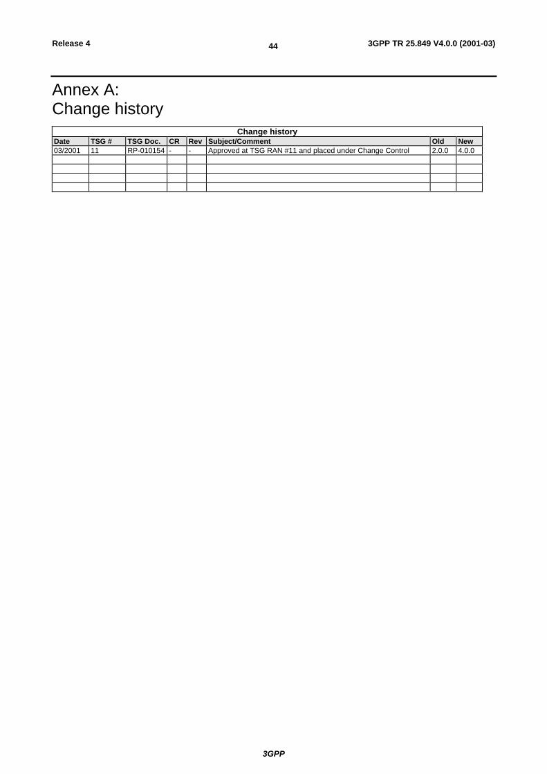
3GPP
3GPP TR 25.849 V4.0.0 (2001-03)44Release 4
Annex A: Change history
Change history Date TSG # TSG Doc. CR Rev Subject/Comment Old New 03/2001 11 RP-010154 - - Approved at TSG RAN #11 and placed under Change Control 2.0.0 4.0.0