technical report - 株式会社qt · technical report 3rd generation partnership project (3gpp);...
TRANSCRIPT
3GPP TR 25.853 V3.0.0 (2000-12)Technical Report
3rd Generation Partnership Project (3GPP);Technical Specification Group (TSG) RAN;
Delay Budget within the Access Stratum(Release 1999)
The present document has been developed within the 3rd Generation Partnership Project (3GPP TM) and may be further elaborated for the purposes of 3GPP. The present document has not been subject to any approval process by the 3GPP Organizational Partners and shall not be implemented. This Specification is provided for future development work within 3GPP only. The Organizational Partners accept no liability for any use of this Specification.Specifications and reports for implementation of the 3GPP TM system should be obtained via the 3GPP Organizational Partners' Publications Offices.
3GPP
3GPP TR 25.853 V3.0.0 (2000-12)2Release 1999
Keywords <keyword[, keyword]>
3GPP
Postal address
3GPP support office address 650 Route des Lucioles - Sophia Antipolis
Valbonne - FRANCE Tel.: +33 4 92 94 42 00 Fax: +33 4 93 65 47 16
Internet http://www.3gpp.org
Copyright Notification
No part may be reproduced except as authorized by written permission. The copyright and the foregoing restriction extend to reproduction in all media.
© 2000, 3GPP Organizational Partners (ARIB, CWTS, ETSI, T1, TTA,TTC).
All rights reserved.
3GPP
3GPP TR 25.853 V3.0.0 (2000-12)3Release 1999
Contents Foreword............................................................................................................................................................ 4
1 Scope ....................................................................................................................................................... 5
2 References ............................................................................................................................................... 5
3 Definitions, symbols and abbreviations................................................................................................... 6 3.1 Definitions..........................................................................................................................................................6 3.2 Symbols..............................................................................................................................................................6 3.3 Abbreviations .....................................................................................................................................................6
4 External requirements on UTRAN .......................................................................................................... 7 4.1 General ...............................................................................................................................................................7 4.2 Performance Expectations..................................................................................................................................9 4.2.1 Real Time Services.......................................................................................................................................9
5 UTRAN Delay Components.................................................................................................................... 9 5.1 General ...............................................................................................................................................................9 5.2 UTRAN Network Components ..........................................................................................................................9 5.2.1 Macro-diversity Combining Delay ...............................................................................................................9 5.2.2 Interleaving for Convolutional and Turbo Coding (U3).............................................................................10 5.2.3 MAC Scheduling Delay (U4) .....................................................................................................................10 5.2.4 Re-transmission Delay (U5) .......................................................................................................................10 5.2.5 Radio Interface Propagation Delay (U6) ....................................................................................................11 5.2.6 Processing Delays (U2) ..............................................................................................................................11 5.3 Transport Network ...........................................................................................................................................12 5.3.1 General .......................................................................................................................................................12 5.3.2 Multiplexing and De-multiplexing Delay (TN1)........................................................................................14 5.3.3 Play-out Buffer Delay (U1) ........................................................................................................................15 5.3.4 Transmission Delay ....................................................................................................................................15 5.3.5 Media Delay (TN2) ....................................................................................................................................15 5.3.6 Switching/and Cross-Connecting Delay (TN3) ..........................................................................................16
6 UTRAN Delay Estimation..................................................................................................................... 16 6.1 UTRAN Reference Configuration....................................................................................................................16 6.2 Network Assumptions ......................................................................................................................................17 6.3 Traffic Assumptions.........................................................................................................................................17 6.4 Delay Budget Evaluation .................................................................................................................................18
Annex A: ......................................................................................................................... 21 A.1 Non Access Stratum Delay Components .........................................................................................................21 A.1.1 Transcoding for Speech Services................................................................................................................21 A.1.2 Core Network .............................................................................................................................................21 A.1.3 User Equipment ..........................................................................................................................................21
Annex B: Open Issues relating to this specification.................................................................................... 22
Annex C (informative): Change history ...................................................................................................... 23
3GPP
3GPP TR 25.853 V3.0.0 (2000-12)4Release 1999
Foreword This Technical Report has been produced by the 3rd Generation Partnership Project (3GPP), Technical Specification Group RAN.
The contents of the present document are subject to continuing work within the TSG and may change following formal TSG approval. Should the TSG modify the contents of the present document, it will be re-released by the TSG with an identifying change of release date and an increase in version number as follows:
Version x.y.z
where:
x the first digit:
1 presented to TSG for information;
2 presented to TSG for approval;
3 or greater indicates TSG approved document under change control.
y the second digit is incremented for all changes of substance, i.e. technical enhancements, corrections, updates, etc.
z the third digit is incremented when editorial only changes have been incorporated in the document.
3GPP
3GPP TR 25.853 V3.0.0 (2000-12)5Release 1999
1 Scope The present document evaluates the delay components introduced within the Access Stratum to provide guidelines useful both to provider for the dimensioning of a network and to manufacturers for the design of node elements. While the analysis of the possible delay sources is performed in an exhaustive way, the evaluation of single and global delay figures is limited to the case of Real Time services.
The estimation of Non Real Time service delays is not in scope of Release 99 and, therefore, it will not be considered in the present version of the Technical Report.
2 References The following documents contain provisions which, through reference in this text, constitute provisions of the present document.
• References are either specific (identified by date of publication, edition number, version number, etc.) or non-specific.
• For a specific reference, subsequent revisions do not apply.
• For a non-specific reference, the latest version applies.
[1] 3G TS 22.105 (V3.6.0): "Technical Specification Group Services and System Aspects Service Aspects; Service and Service Capabilities" (1999-10).
[2] 3G TR 101 111 (V3.0.1): "Requirements for the UMTS Terrestrial Radio Access system (UTRA) (UMTS 21.01 version 3.0.1)" (1997-10).
[3] 3G TR 22.25 (V3.1.0): "Quality of Service and Network Performance (UMTS 22.25 version 3.1.0)" (1998-03).
[4] ITU-T Recommendation G.174 (1994-06): "Transmission Performance Objectives for Terrestrial Digital Wireless Systems using Portable Terminals to access the PSTN".
[5] ITU-T Recommendation G.114 (1996-02): "Transmission Systems and Media General Characteristics of International Telephone Connections and International Telephone Circuits - O n e-Way Transmission Time".
[6] 3G TR 30.20 (V3.1.0): "Technical characteristics, capabilities and limitations of mobile satellite systems applicable to the UMTS (UMTS 30.20 version 3.1.0)" (1998-01).
[7] ITU-T Recommendation I.356 (1996-10): "Overall network aspects and functions – Performance objectives".
[8] ATM Forum af-vtoa-0113.000 (1999-02): "ATM Trunking using AAL2 for Narrowband Services".
[9] ITU-T Recommendation I.363.2 (1997-10): "B-ISDN ATM Adaptation Layer Specification Type 2 AAL".
[10] Liu Chunlei, Munir Sohail and Jain Raj: "Packing density of Voice Trunking using AAL2", paper submitted to Globelcom'99.
[11] ATM Forum 98-0630 (1998-10): "Packet Delay Variation in Voice Trunking using AAL2, COMSAT Laboratories".
[12] ATM Forum 98-0830 (1998-12): "Packing Density of Voice Trunking using AAL2, The Ohio State University & NOKIA Research Center (Burlington)".
[13] 3G TR 101 631 (V6.0.0): "Technical performance objectives (GSM 03.05 version 6.0.0 Release 1997)" (1999-04).
[14] ITU-T Recommendation G.168 (1997-04): "Digital network echo cancellers".
3GPP
3GPP TR 25.853 V3.0.0 (2000-12)6Release 1999
[15] 3G TR 25.944 (V1.0.1): "Channel coding and multiplexing examples" 3GPP TSG RAN WG1.
3 Definitions, symbols and abbreviations
3.1 Definitions For the purposes of the present document, the [following] terms and definitions [given in ... and the following] apply.
example: text used to clarify abstract rules by applying them literally.
3.2 Symbols For the purposes of the present document, the following symbols apply:
RT Real Time
NRT Non Real Time
3.3 Abbreviations For the purposes of the present document, the following abbreviations apply:
AAL ATM Adaptation Layer AMR Adaptive Multi Rate ATM Asynchronous Transfer Mode BER Bit Error Ratio CBR Constant Bit Rate CDV Cell Delay Variation CN Core Network CPS Common Part Sublayer CRC Cyclic Redundancy Check CTD Cell Transfer Delay DL Downlink DRNC Drift RNS FDD Frequency Division Duplexing FEC Forward error Coding FER Frame Error Ratio GGSN Gateway GPRS Support Node GTP GPRS Tunnelling Protocol IMA Inverse Multiplexing on ATM ISDN Integrated Services Digital Network ITU International Telecommunication Union MAC Medium Access Control MDC Macro-Diversity Combining MP Measurement Point MSC Mobile Services Switching Centre NAK Not Acknowledged NRT Non Real Time PCM Pulse Code Modulation PCR Peak Cell Rate PDF Probability Distribution Function PDH Plesiochronous Digital Hierarchy PDV Packet Delay Variation PS Packet Switched PSTN Public Switched Telephone Network PTD Packet Transfer Delay RAN Radio Access Network
3GPP
3GPP TR 25.853 V3.0.0 (2000-12)7Release 1999
RLC Radio Link Control RNC Radio Network Controller RT Real Time SAP Service Access Point SAR Segmentation And Re-assembly SCR Sustainable Cell Rate SDH Synchronous Digital Hierarchy SDU Service Data Unit SRNC Serving RNC STM Synchronous Transfer Mode TDD Time Division Duplexing TFO Tandem Free Operation TR Technical Report TRAU Transcoder Rate Adaption Unit TTI Transmission Time Interval UE User Equipment UL Uplink UMTS Universal Mobile Telecommunication System UTRAN UMTS Terrestrial Radio Access Network VCC Virtual Channel Connection
4 External requirements on UTRAN
4.1 General Reference [1] describes a range of Quality of Service (QoS) requirements to be supported by bearer services in UMTS.
The elements considered to characterise a bearer service are:
• Data rate;
• Maximum transfer delay defined as the time between the request to transfer the information at the originating access point to its delivery at the terminating access point;
• Maximum delay variation;
• BER/FER requirements;
• Information loss.
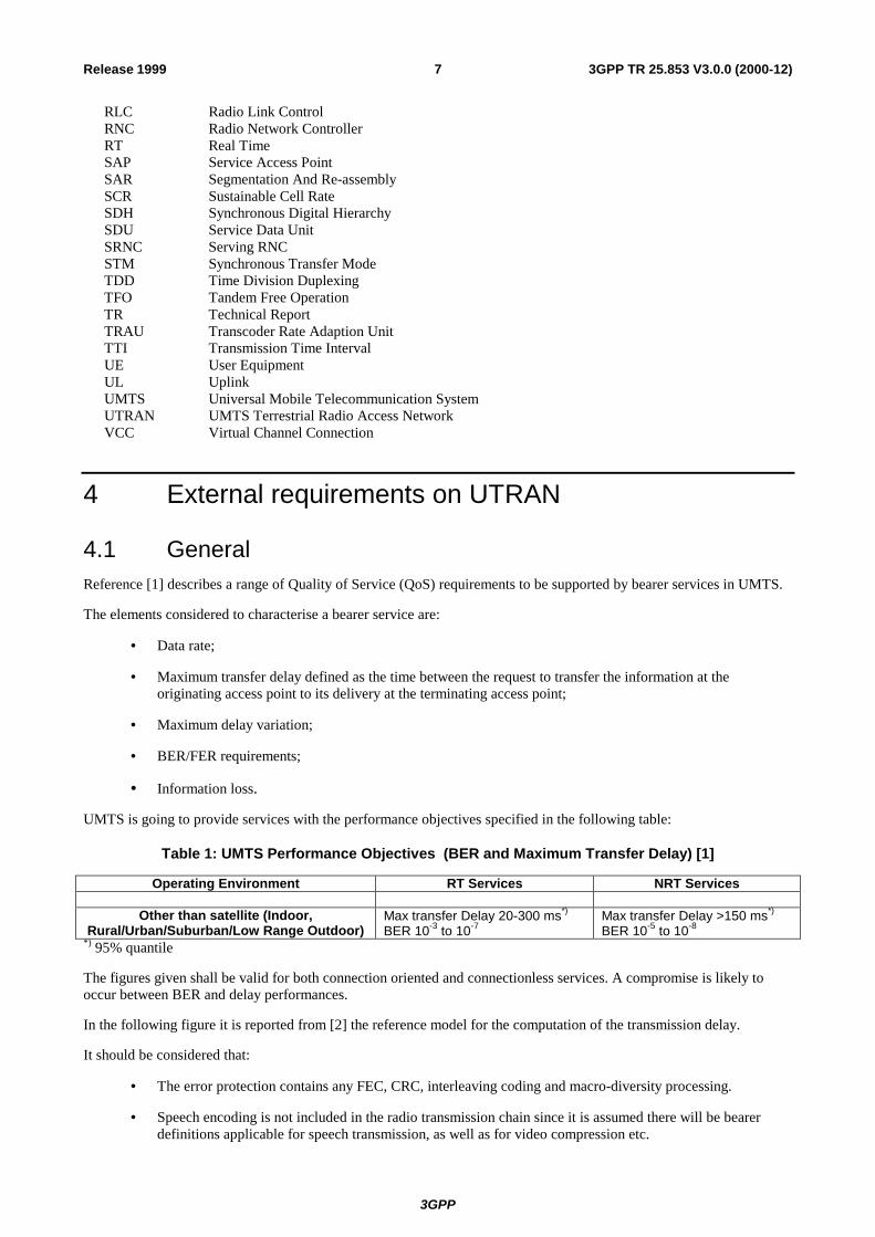
UMTS is going to provide services with the performance objectives specified in the following table:
Table 1: UMTS Performance Objectives (BER and Maximum Transfer Delay) [1]
Operating Environment RT Services NRT Services
Other than satellite (Indoor, Rural/Urban/Suburban/Low Range Outdoor)
Max transfer Delay 20-300 ms*) BER 10-3 to 10-7
Max transfer Delay >150 ms*) BER 10-5 to 10-8
*) 95% quantile
The figures given shall be valid for both connection oriented and connectionless services. A compromise is likely to occur between BER and delay performances.
In the following figure it is reported from [2] the reference model for the computation of the transmission delay.
It should be considered that:
• The error protection contains any FEC, CRC, interleaving coding and macro-diversity processing.
• Speech encoding is not included in the radio transmission chain since it is assumed there will be bearer definitions applicable for speech transmission, as well as for video compression etc.
3GPP
3GPP TR 25.853 V3.0.0 (2000-12)8Release 1999
The one-way delay figures are only applicable for defining the radio technology bearers and not for defining the complete access delay for the radio access network. This means that the total delay will be larger. Thus the figures Tt and Ti must be lower than the requirement for total delay in the access network.
SourceEncoding
ApplicationdependentARQ
MUX Modulationetc.
ErrorProtection
ErrorProtection
Tt=One way transmission delay
Radio LinkProtocol,(ARQ)
CN (U)RAN: UTRA part
Iu
Ti=ARQ delay
SourceDecoding
ApplicationdependentARQ
De-Mux Detectorsetc.
ErrorHandling
ErrorHandling
Radio LinkProtocol,(ARQ)
MS
Figure 1: Reference Model for Transmission Delay [2]
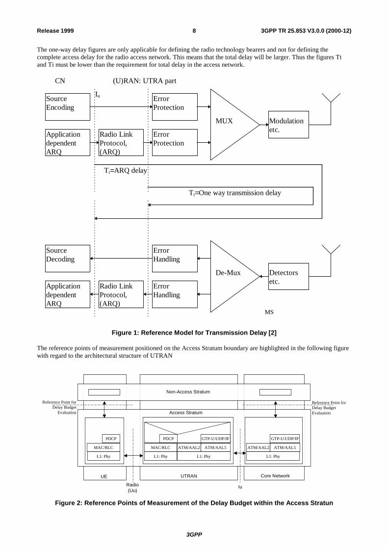
The reference points of measurement positioned on the Access Stratum boundary are highlighted in the following figure with regard to the architectural structure of UTRAN
Radio(Uu)
Iu
Reference Point forDelay Budget
Evaluation
UE UTRAN Core Network
Non-Access Stratum
Access Stratum
L1: Phy
MAC/RLC
PDCP
L1: Phy
MAC/RLC
PDCP
L1: Phy
ATM/AAL2
GTP-U/UDP/IP
ATM/AAL5
L1: Phy
ATM/AAL2
GTP-U/UDP/IP
ATM/AAL5
Reference Point forDelay BudgetEvaluation
Figure 2: Reference Points of Measurement of the Delay Budget within the Access Stratun
3GPP
3GPP TR 25.853 V3.0.0 (2000-12)9Release 1999
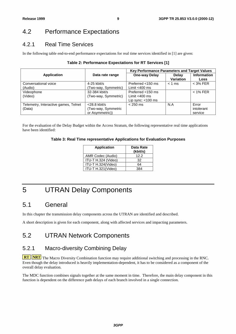
4.2 Performance Expectations
4.2.1 Real Time Services In the following table end-to-end performance expectations for real time services identified in [1] are given:
Table 2: Performance Expectations for RT Services [1]
Key Performance Parameters and Target Values Application Data rate range One-way Delay Delay
Variation Information
Loss Conversational voice (Audio)
4-25 kbit/s (Two-way, Symmetric)
Preferred <150 ms Limit <400 ms
< 1 ms < 3% FER
Videophone (Video)
32-384 kbit/s (Two-way, Symmetric)
Preferred <150 ms Limit <400 ms Lip sync: <100 ms
< 1% FER
Telemetry, Interactive games, Telnet (Data)
<28.8 kbit/s (Two-way, Symmetric or Asymmetric))
< 250 ms N.A Error intolerant service
For the evaluation of the Delay Budget within the Access Stratum, the following representative real time applications have been identified:
Table 3: Real Time representative Applications for Evaluation Purposes
Application Data Rate (kbit/s)
AMR Codec (Audio) 12.2 ITU-T H.324 (Video) 32 ITU-T H.324(Video) 64 ITU-T H.321(Video) 384
5 UTRAN Delay Components
5.1 General In this chapter the transmission delay components across the UTRAN are identified and described.
A short description is given for each component, along with affected services and impacting parameters.
5.2 UTRAN Network Components
5.2.1 Macro-diversity Combining Delay RT NRT The Macro Diversity Combination function may require additional switching and processing in the RNC.
Even though the delay introduced is heavily implementation-dependent, it has to be considered as a component of the overall delay evaluation.
The MDC function combines signals together at the same moment in time. Therefore, the main delay component in this function is dependent on the difference path delays of each branch involved in a single connection.
3GPP
3GPP TR 25.853 V3.0.0 (2000-12)10Release 1999
5.2.2 Interleaving for Convolutional and Turbo Coding (U3) RT NRT Interleaving is a physical layer function that segments transport blocks over several radio frames. These
blocks can be interleaved over 1, 2, 4, and 8 transport blocks. Thus, the interleaving will add a large transmission delay to the data stream over the air interface directly proportional to the interleaving factor.
NRT Turbo coding has it own internal interleaving mechanism, for data services this is an additional delay increasing with the block dimension and decreasing with the service data rate.
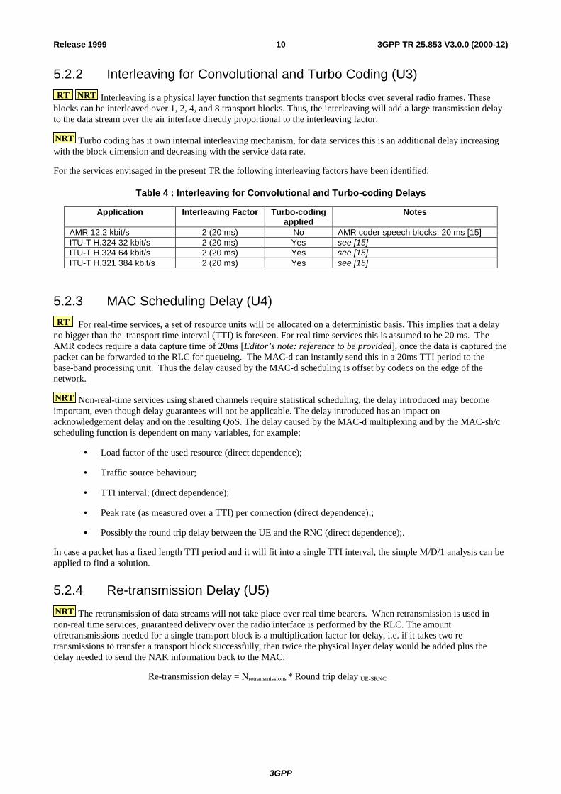
For the services envisaged in the present TR the following interleaving factors have been identified:
Table 4 : Interleaving for Convolutional and Turbo-coding Delays
Application Interleaving Factor Turbo-coding applied
Notes
AMR 12.2 kbit/s 2 (20 ms) No AMR coder speech blocks: 20 ms [15] ITU-T H.324 32 kbit/s 2 (20 ms) Yes see [15] ITU-T H.324 64 kbit/s 2 (20 ms) Yes see [15] ITU-T H.321 384 kbit/s 2 (20 ms) Yes see [15]
5.2.3 MAC Scheduling Delay (U4) RT For real-time services, a set of resource units will be allocated on a deterministic basis. This implies that a delay
no bigger than the transport time interval (TTI) is foreseen. For real time services this is assumed to be 20 ms. The AMR codecs require a data capture time of 20ms [Editor’s note: reference to be provided], once the data is captured the packet can be forwarded to the RLC for queueing. The MAC-d can instantly send this in a 20ms TTI period to the base-band processing unit. Thus the delay caused by the MAC-d scheduling is offset by codecs on the edge of the network.
NRT Non-real-time services using shared channels require statistical scheduling, the delay introduced may become important, even though delay guarantees will not be applicable. The delay introduced has an impact on acknowledgement delay and on the resulting QoS. The delay caused by the MAC-d multiplexing and by the MAC-sh/c scheduling function is dependent on many variables, for example:
• Load factor of the used resource (direct dependence);
• Traffic source behaviour;
• TTI interval; (direct dependence);
• Peak rate (as measured over a TTI) per connection (direct dependence);;
• Possibly the round trip delay between the UE and the RNC (direct dependence);.
In case a packet has a fixed length TTI period and it will fit into a single TTI interval, the simple M/D/1 analysis can be applied to find a solution.
5.2.4 Re-transmission Delay (U5) NRT The retransmission of data streams will not take place over real time bearers. When retransmission is used in non-real time services, guaranteed delivery over the radio interface is performed by the RLC. The amount ofretransmissions needed for a single transport block is a multiplication factor for delay, i.e. if it takes two re-transmissions to transfer a transport block successfully, then twice the physical layer delay would be added plus the delay needed to send the NAK information back to the MAC:
Re-transmission delay = Nretransmissions * Round trip delay UE-SRNC
3GPP
3GPP TR 25.853 V3.0.0 (2000-12)11Release 1999
The maximum number of allowed re-transmissions defines the weight introduced by this component according to the following formula:
Max Re-transmission Delay = NretransmissionsMax. * (ITC + PPO + MAC + MDC + AAL +MD + SD) * 2.
Where:
ITC = Interleaving and Turbo Coding delay PPO = Packetisation, De-packetisation and End-System Play-Out delay MAC = MAC Scheduling delay MDC = Macro-diversity Combining delay AAL = AAL Packetisation, Multiplexing and De-packetisation delay MD = Media delay SD = Switch delay
This delay component can be reduced if prioritisation mechanisms are used for data re-transmission.
5.2.5 Radio Interface Propagation Delay (U6) Since in one millisecond radio waves cover a distance of around 300 km, the delay introduced by the component can be neglected even considering a macro cell environment.
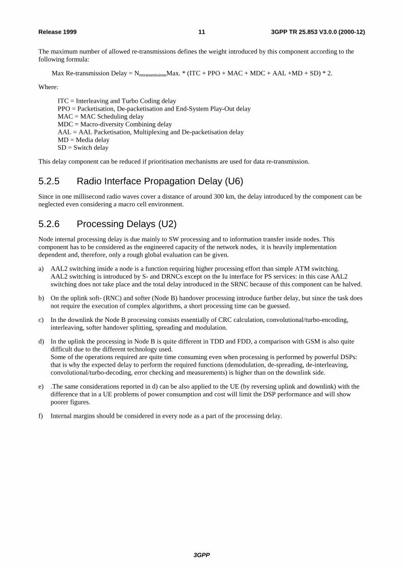
5.2.6 Processing Delays (U2) Node internal processing delay is due mainly to SW processing and to information transfer inside nodes. This component has to be considered as the engineered capacity of the network nodes, it is heavily implementation dependent and, therefore, only a rough global evaluation can be given.
a) AAL2 switching inside a node is a function requiring higher processing effort than simple ATM switching. AAL2 switching is introduced by S- and DRNCs except on the Iu interface for PS services: in this case AAL2 switching does not take place and the total delay introduced in the SRNC because of this component can be halved.
b) On the uplink soft- (RNC) and softer (Node B) handover processing introduce further delay, but since the task does not require the execution of complex algorithms, a short processing time can be guessed.
c) In the downlink the Node B processing consists essentially of CRC calculation, convolutional/turbo-encoding, interleaving, softer handover splitting, spreading and modulation.
d) In the uplink the processing in Node B is quite different in TDD and FDD, a comparison with GSM is also quite difficult due to the different technology used. Some of the operations required are quite time consuming even when processing is performed by powerful DSPs: that is why the expected delay to perform the required functions (demodulation, de-spreading, de-interleaving, convolutional/turbo-decoding, error checking and measurements) is higher than on the downlink side.
e) .The same considerations reported in d) can be also applied to the UE (by reversing uplink and downlink) with the difference that in a UE problems of power consumption and cost will limit the DSP performance and will show poorer figures.
f) Internal margins should be considered in every node as a part of the processing delay.
3GPP
3GPP TR 25.853 V3.0.0 (2000-12)12Release 1999
To derive the following figures, [13] has been used as a guideline: from this starting point technological considerations and the above mentioned aspects have been considered to provide the following estimations1:
• 5 ms for RNC, • 2 ms for DL Node B,
• 15 ms for UL Node B, no turbo decoding, • 15 ms + 0.15ms*throughput for UL Node B, with turbo decoding (throughput in kbit/s, evaluated by applying
Maximum A-posteriori Probability (MAP) algorithm on a state-of-the-art DSP), • 15 for UL UE,
• 15 ms for DL UE, no turbo decoding • 20 ms for DL UE with turbo decoding
[Editor’s Note: When NRT high speed services will be analysed, the coding time (function of the block length and neglectable for the considered services) shall be also included]
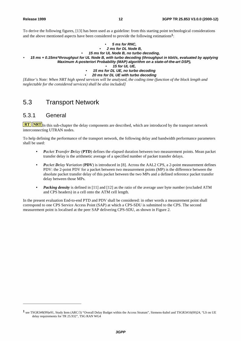
5.3 Transport Network
5.3.1 General RT NRT In this sub-chapter the delay components are described, which are introduced by the transport network
interconnecting UTRAN nodes.
To help defining the performance of the transport network, the following delay and bandwidth performance parameters shall be used:
• Packet Transfer Delay (PTD) defines the elapsed duration between two measurement points. Mean packet transfer delay is the arithmetic average of a specified number of packet transfer delays.
• Packet Delay Variation (PDV) is introduced in [8]. Across the AAL2 CPS, a 2-point measurement defines PDV: the 2-point PDV for a packet between two measurement points (MP) is the difference between the absolute packet transfer delay of this packet between the two MPs and a defined reference packet transfer delay between those MPs.
• Packing density is defined in [11] and [12] as the ratio of the average user byte number (excluded ATM and CPS headers) in a cell onto the ATM cell length.
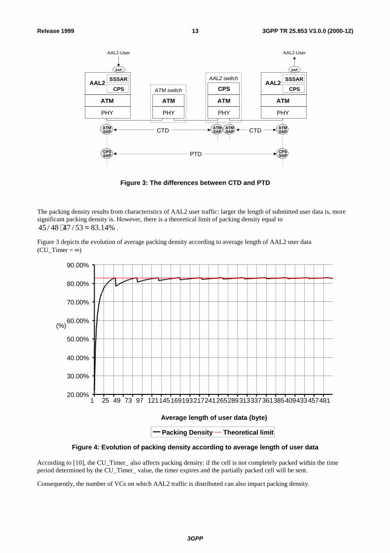
In the present evaluation End-to-end PTD and PDV shall be considered: in other words a measurement point shall correspond to one CPS Service Access Point (SAP) at which a CPS-SDU is submitted to the CPS. The second measurement point is localised at the peer SAP delivering CPS-SDU, as shown in Figure 2.
1 see TSGR3#8(99)e91, Study Item (ARC/3) “Overall Delay Budget within the Access Stratum”, Siemens-Italtel and TSGR3#16(00)24, “LS on UE delay requirements for TR 25.932”, TSG RAN WG4
3GPP
3GPP TR 25.853 V3.0.0 (2000-12)13Release 1999
AAL2CPS
SSSAR
ATM
PHY PHY
ATM
AAL2-User
SAP
PHY
ATM
CPSAAL2
CPS
SSSAR
ATM
PHY
ATM switch
AAL2 switch
SAP
AAL2-User
ATMSAP
ATMSAP
ATMSAP
ATMSAPCTD CTD
CPSSAP
CPSSAPPTD
Figure 3: The differences between CTD and PTD
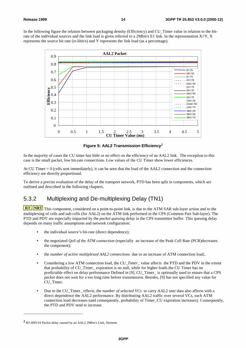
The packing density results from characteristics of AAL2 user traffic: larger the length of submitted user data is, more significant packing density is. However, there is a theoretical limit of packing density equal to
%14.8353/4748/45 ≈⋅ .
Figure 3 depicts the evolution of average packing density according to average length of AAL2 user data (CU_Timer = ∞)
20.00%
30.00%
40.00%
50.00%
60.00%
70.00%
80.00%
90.00%
1 25 49 73 97 121145169193217241265289313337361385409433457481
Average length of user data (byte)
(%)
Packing Density Theoretical limit
Figure 4: Evolution of packing density according to average length of user data
According to [10], the CU_Timer_ also affects packing density: if the cell is not completely packed within the time period determined by the CU_Timer_ value, the timer expires and the partially packed cell will be sent.
Consequently, the number of VCs on which AAL2 traffic is distributed can also impact packing density.
3GPP
3GPP TR 25.853 V3.0.0 (2000-12)14Release 1999
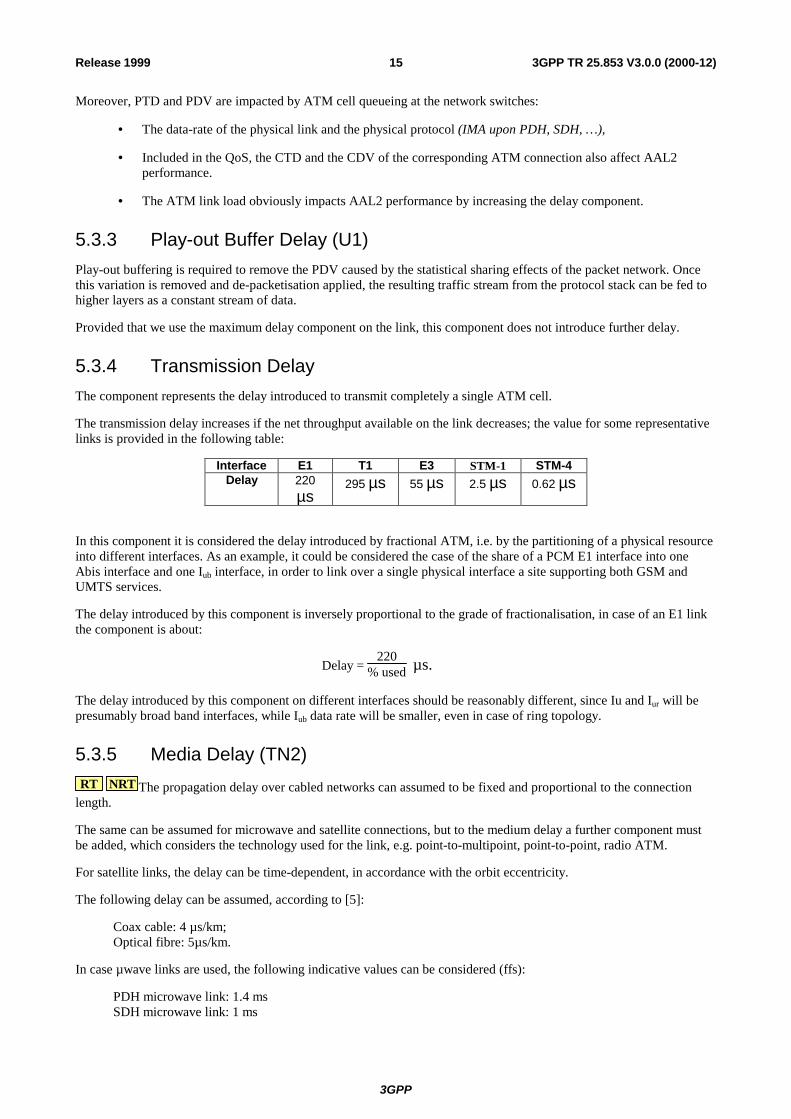
In the following figure the relation between packaging density (Efficiency) and CU_Timer value in relation to the bit-rate of the individual sources and the link load is given referred to a 2Mbit/s E1 link. In the representation X//Y, X represents the source bit rate (in kbit/s) and Y represents the link load (as a percentage).
AAL2 Packet
0
0.1
0.2
0.3
0.4
0.5
0.6
0.7
0.8
0.9
0 0.5 1 1.5 2 2.5 3 3.5 4 4.5 5CU Timer Value (ms)
Effic
ienc
y
8/ / 2508/ / 508/ / 7532/ / 25032/ / 5032/ / 7564/ / 25064/ / 5064/ / 75144/ / 250144/ / 50144/ / 75384/ / 25384/ / 50384/ / 75
Figure 5: AAL2 Transmission Efficiency2
In the majority of cases the CU timer has little or no effect on the efficiency of an AAL2 link. The exception to this case is the small packet, low bit-rate connections. Low values of the CU Timer show lower efficiences.
At CU Timer = 0 (cells sent immediately), it can be seen that the load of the AAL2 connection and the connection efficiency are directly proportional.
To derive a precise evaluation of the delay of the transport network, PTD has been split in components, which are outlined and described in the following chapters.
5.3.2 Multiplexing and De-multiplexing Delay (TN1) RT NRT This component, considered on a point-to-point link, is due to the ATM SAR sub-layer action and to the
multiplexing of cells and sub-cells (for AAL2) on the ATM link performed in the CPS (Common Part Sub-layer). The PTD and PDV are especially impacted by the packet queuing delay in the CPS transmitter buffer. This queuing delay depends on many traffic assumptions and network configuration:
• the individual source’s bit-rate (direct dependence);
• the negotiated QoS of the ATM connection (especially an increase of the Peak Cell Rate (PCR)decreases the component);
• the number of active multiplexed AAL2 connections due to an increase of ATM connection load;.
• Considering a low ATM connection load, the CU_Timer_ value affects the PTD and the PDV in the extent that probability of CU_Timer_ expiration is no null, while for higher loads the CU Timer has no predictable effect on delay performance Defined in [9], CU_Timer_ is optionally used to ensure that a CPS packet does not wait for a too long time before transmission. Besides, [9] has not specified any value for CU_Timer.
• Due to the CU_Timer_ effects, the number of selected VCs to carry AAL2 user data also affects with a direct dependence the AAL2 performance. By distributing AAL2 traffic over several VCs, each ATM connection load decreases (and consequently, probability of Timer_CU expiration increases). Consequently, the PTD and PDV tend to increase.
2 R3-000134 Packet delay caused by an AAL2 2Mbit/s Link, Siemens
3GPP
3GPP TR 25.853 V3.0.0 (2000-12)15Release 1999
Moreover, PTD and PDV are impacted by ATM cell queueing at the network switches:
• The data-rate of the physical link and the physical protocol (IMA upon PDH, SDH, …),
• Included in the QoS, the CTD and the CDV of the corresponding ATM connection also affect AAL2 performance.
• The ATM link load obviously impacts AAL2 performance by increasing the delay component.
5.3.3 Play-out Buffer Delay (U1) Play-out buffering is required to remove the PDV caused by the statistical sharing effects of the packet network. Once this variation is removed and de-packetisation applied, the resulting traffic stream from the protocol stack can be fed to higher layers as a constant stream of data.
Provided that we use the maximum delay component on the link, this component does not introduce further delay.
5.3.4 Transmission Delay The component represents the delay introduced to transmit completely a single ATM cell.
The transmission delay increases if the net throughput available on the link decreases; the value for some representative links is provided in the following table:
Interface E1 T1 E3 STM-1 STM-4 Delay 220
µs 295 µs 55 µs 2.5 µs 0.62 µs
In this component it is considered the delay introduced by fractional ATM, i.e. by the partitioning of a physical resource into different interfaces. As an example, it could be considered the case of the share of a PCM E1 interface into one Abis interface and one Iub interface, in order to link over a single physical interface a site supporting both GSM and UMTS services.
The delay introduced by this component is inversely proportional to the grade of fractionalisation, in case of an E1 link the component is about:
Delay = 220
% used µs.
The delay introduced by this component on different interfaces should be reasonably different, since Iu and Iur will be presumably broad band interfaces, while Iub data rate will be smaller, even in case of ring topology.
5.3.5 Media Delay (TN2) RT NRT The propagation delay over cabled networks can assumed to be fixed and proportional to the connection
length.
The same can be assumed for microwave and satellite connections, but to the medium delay a further component must be added, which considers the technology used for the link, e.g. point-to-multipoint, point-to-point, radio ATM.
For satellite links, the delay can be time-dependent, in accordance with the orbit eccentricity.
The following delay can be assumed, according to [5]:
Coax cable: 4 µs/km; Optical fibre: 5µs/km.
In case µwave links are used, the following indicative values can be considered (ffs):
PDH microwave link: 1.4 ms SDH microwave link: 1 ms
3GPP
3GPP TR 25.853 V3.0.0 (2000-12)16Release 1999
Point-to-multipoint microwave link: 5 ms
According to [5] and [6] the delay introduced by a satellite link can range between 60ms (max. value for LEOs) and 310 ms (max. value for HEOs).
It is therefore suggested to allow a single satellite hop along a link over the UTRAN between a UE and the Core Network and to allow a relaxation of the delay expectations.
5.3.6 Switching/and Cross-Connecting Delay (TN3) RT NRT This is the component due to switching nodes (Cross-Connects and Switches) along UTRAN terrestrial
interfaces, only. Its value is proportional to the number of intervening nodes and has a heavy direct dependence on the traffic load of each node. [7] defines 300 µs as the maximum delay for real-time services through ATM switches. Even if the definition of this component is not clear in the quoted reference, this assumption is accepted as a worst case for the pure switching function of an ATM switch/cross-connect.
For the evaluation of the overall delay introduced by an ATM switch/cross-connect the transmission delay will be further considered and added to this component.
6 UTRAN Delay Estimation
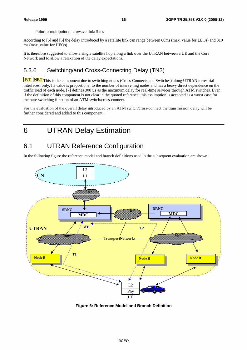
6.1 UTRAN Reference Configuration In the following figure the reference model and branch definitions used in the subsequent evaluation are shown.
Node B
SRNCMDC
UE
Node B
dT
DRNCMDC
Node B
TransportNetworks
T2
T1
PhyL2
UTRAN
L1L2
CN
Figure 6: Reference Model and Branch Definition
3GPP
3GPP TR 25.853 V3.0.0 (2000-12)17Release 1999
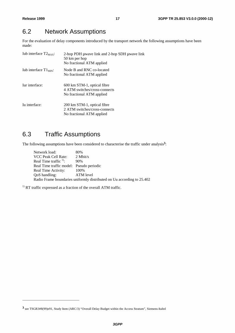
6.2 Network Assumptions For the evaluation of delay components introduced by the transport network the following assumptions have been made:
Iub interface T2MAX: 2-hop PDH µwave link and 2-hop SDH µwave link 50 km per hop No fractional ATM applied
Iub interface T1MIN: Node B and RNC co-located No fractional ATM applied
Iur interface: 600 km STM-1, optical fibre 4 ATM switches/cross-connects No fractional ATM applied
Iu interface: 200 km STM-1, optical fibre 2 ATM switches/cross-connects No fractional ATM applied
6.3 Traffic Assumptions The following assumptions have been considered to characterise the traffic under analysis3:
Network load: 80% VCC Peak Cell Rate: 2 Mbit/s Real Time traffic 1): 90% Real Time traffic model: Pseudo periodic Real Time Activity: 100% QoS handling: ATM level Radio Frame boundaries uniformly distributed on Uu according to 25.402
1) RT traffic expressed as a fraction of the overall ATM traffic.
3 see TSGR3#8(99)e91, Study Item (ARC/3) “Overall Delay Budget within the Access Stratum”, Siemens-Italtel
3GPP
3GPP TR 25.853 V3.0.0 (2000-12)18Release 1999
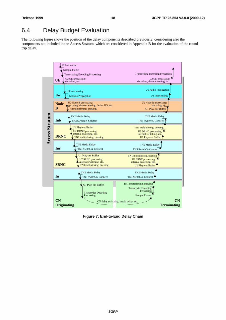
6.4 Delay Budget Evaluation The following figure shows the position of the delay components described previously, considering also the components not included in the Access Stratum, which are considered in Appendix B for the evaluation of the round trip delay.
Echo Control
Sample Frame
Transcoding Encoding Processing
U3 Interleaving
U6 Radio Propagation
U2 Node B processing:decoding, de-interleaving, Softer HO, etc.TN1multiplexing, queuing
TN2 Media Delay
TN3 Switch/X-Connect
U1 Play-out BufferU2 DRNC processing,internal switching, etc.TN1 multiplexing, queuing
CN delay switching, media delay, etc.
Transcoder DecodingProcessing
TN3 Switch/X-Connect
U1 Play-out BufferU2 SRNC processing,internal switching, etc.TN1multiplexing, queuing
TN2 Media Delay
TN3 Switch/X-Connect
TN2 Media Delay
U1 Play-out Buffer
Sample Frame
Transcoding Decoding Processing
U3 Interleaving
U6 Radio Propagation
U2 Node B processing:encoding, etc.
TN2 Media Delay
TN3 Switch/X-Connect
U1 Play-out Buffer
U2 DRNC processing,internal switching, etc.
TN1 multiplexing, queuing
Transcoder EncodingProcessing
U1 Play-out Buffer
U2 SRNC processing,internal switching, etc.
TN1 multiplexing, queuing
TN3 Switch/X-Connect
TN2 Media Delay
U1 Play-out Buffer
TN1 multiplexing, queuing
TN3 Switch/X-Connect
TN2 Media Delay
U2 UE processing:encoding, etc.
U2 UE processing:decoding, de-interleaving, etc.
CNOriginating
CNTerminating
Iu
Iur
Iub
SRNC
DRNC
NodeB
Uu
UE
Acc
ess S
trat
um
Figure 7: End-to-End Delay Chain
3GPP
3GPP TR 25.853 V3.0.0 (2000-12)19Release 1999
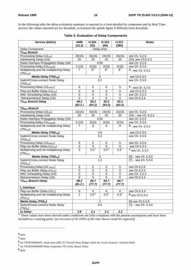
In the following table the delay evaluation summary is reported in a form detailed by component and by Real Time service; the values reported are for downlink, in brackets the uplink figure if different from downlink:
Table 5: Evaluation of Delay Components
Service (kbit/s) AMR (12.2)
H.324 (32)
H.324 (64)
H.321 (384)
Notes
Delay Component Delay (ms) T1MIN Branch Processing Delay (U2UE) 15(15) 15(15) 15(15) 15(15) see Ch. 5.2.6 Interleaving Delay (U3) 20 20 20 20 [15], see Ch.5.2.2 Radio Interface Propagation Delay (U6) 0.05 see Ch. 5.2.5 Processing Delay (U2NodeB) 2 (15) 2(15) 2(15) 2(15) see Ch. 5.2.6 Multiplexing and De-multiplexing Delay (TN1Iub)
7 8*) 8*) 8*) 4:- see Ch. 5.3.2
Media Delay (TN2Iub) 0 see Ch.5.3.5 Switch/Cross-connect Node Delay (TN3Iub)
0.2 see Ch. 5.3.6
Processing Delay (U2SRNC) 5 5 5 5 5 - see Ch. 5.2.6 Play-out Buffer Delay (U1Iub) 0 0 0 0 see Ch.5.3.3 MAC Scheduling Delay (U4) 0 0 0 0 see Ch. 5.2.3 Retransmission Delay (U5) 0 0 0 0 see Ch.5.2.4 T1MIN Branch Delay 49.2
(62.2 )50.2
(63.2) 50.2
(63.2)50.2
(63.2)
T2MAX Branch Processing Delay (U2UE) 15(15) 15(15) 15(15) 15(15) see Ch. 5.2.6 Interleaving Delay (U3) 20 20 20 20 [15] – see Ch. 5.2.2 Radio Interface Propagation Delay (U6) 0.05 see Ch. 5.2.5 Processing Delay (U2NodeB) 2 (15) 2(15) 2(15) 2(15) see Ch. 5.2.6 Multiplexing and De-multiplexing Delay (TN1Iub)
7 8 8 8 6 - see Ch. 5.3.2
Media Delay (TN2Iub) 4.8 see Ch.5.3.5 Switch/Cross-connect Node Delay (TN3Iub)
0.2 see Ch. 5.3.6
Processing Delay (U2DRNC) 5 5 5 5 see Ch. 5.2.6 Play-out Buffer Delay (U1Iub) 0 0 0 0 see Ch.5.3.3 Multiplexing and De-multiplexing Delay (TN1Iur)
5 0.5*) 0.5*) 0.5*) 7 see Ch. 5.3.2
Media Delay (TN2Iur) 3 [5] – see Ch. 5.3.5 Switch/Cross-connect Node Delay (TN3Iur)
1.2 [7] – see Ch. 5.3.6
Processing Delay (U2 SRNC) 5 5 5 5 see Ch.5.2.6 Play-out Buffer Delay (U1Iur) 0 0 0 0 see Ch.5.3.3 MAC Scheduling Delay (U4) 0 0 0 0 see Ch. 5.2.3 Retransmission Delay (U5) 0 0 0 0 see Ch.5.2.4 T2MAX Branch Delay 68.2
(81.2 )64.7
(77.7) 64.7
(77.7)64.7
(77.7)
Iu Interface Play-out Buffer Delay (U1Iu) 0 0 0 0 see Ch.5.3.3 Multiplexing and De-multiplexing Delay (TN1Iu)
2 0.5*) 0.5*) 0.5*) 8 see Ch.5.3.2
Media Delay (TN2Iu) 1 [5] see Ch.5.3.5 Switch/Cross-connect Node Delay (TN3Iu)
0.6 [7] – see Ch. 5.3.6
Iu Delay 3.6 2.1 2.1 2.1 *) These values have been derived under conditions not fully compliant with the present assumptions and have been included as a starting point. [an increase of 50-100% of the time shown could be expected]
4 idem 5 idem 6 see TSGR3#8(99)e91, Study Item (ARC/3) “Overall Delay Budget within the Access Stratum”, Siemens-Italtel 7 see TSGR3#3(99)999 Delay component TN1 (AAL delay), Nokia 8 idem
3GPP
3GPP TR 25.853 V3.0.0 (2000-12)20Release 1999
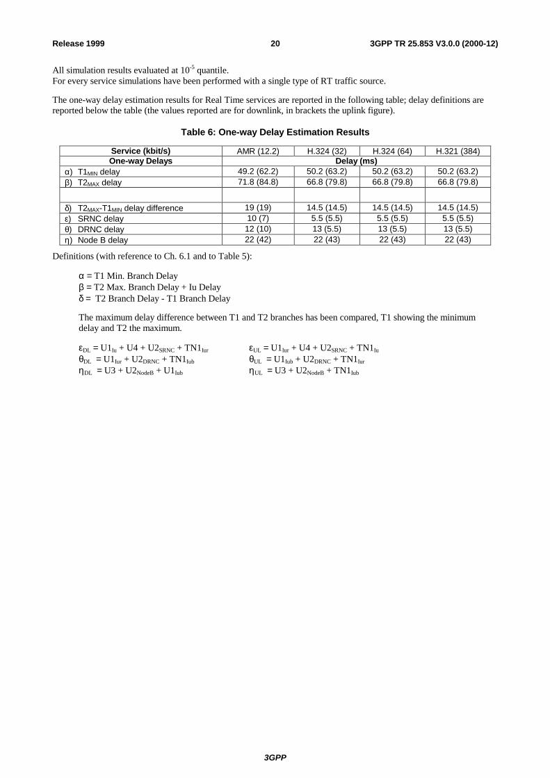
All simulation results evaluated at 10-5 quantile. For every service simulations have been performed with a single type of RT traffic source.
The one-way delay estimation results for Real Time services are reported in the following table; delay definitions are reported below the table (the values reported are for downlink, in brackets the uplink figure).
Table 6: One-way Delay Estimation Results
Service (kbit/s) AMR (12.2) H.324 (32) H.324 (64) H.321 (384) One-way Delays Delay (ms)
α) T1MIN delay 49.2 (62.2) 50.2 (63.2) 50.2 (63.2) 50.2 (63.2) β) T2MAX delay 71.8 (84.8) 66.8 (79.8) 66.8 (79.8) 66.8 (79.8)
δ) T2MAX-T1MIN delay difference 19 (19) 14.5 (14.5) 14.5 (14.5) 14.5 (14.5) ε) SRNC delay 10 (7) 5.5 (5.5) 5.5 (5.5) 5.5 (5.5) θ) DRNC delay 12 (10) 13 (5.5) 13 (5.5) 13 (5.5) η) Node B delay 22 (42) 22 (43) 22 (43) 22 (43)
Definitions (with reference to Ch. 6.1 and to Table 5):
α = T1 Min. Branch Delay β = T2 Max. Branch Delay + Iu Delay δ = T2 Branch Delay - T1 Branch Delay
The maximum delay difference between T1 and T2 branches has been compared, T1 showing the minimum delay and T2 the maximum.
εDL = U1Iu + U4 + U2SRNC + TN1Iur εUL = U1Iur + U4 + U2SRNC + TN1Iu θDL = U1Iur + U2DRNC + TN1Iub θUL = U1Iub + U2DRNC + TN1Iur ηDL = U3 + U2NodeB + U1Iub ηUL = U3 + U2NodeB + TN1Iub
3GPP
3GPP TR 25.853 V3.0.0 (2000-12)21Release 1999
Annex A:
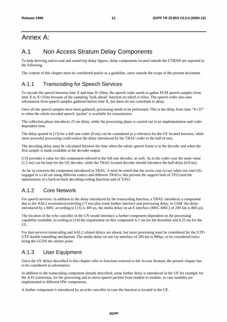
A.1 Non Access Stratum Delay Components To help deriving end-to-end and round-trip delay figures, delay components located outside the UTRAN are reported in the following.
The content of this chapter must be considered purely as a guideline, since outside the scope of the present document.
A.1.1 Transcoding for Speech Services To encode the speech between time X and time X+20ms, the speech coder needs to gather PCM speech samples from time X to X+25ms because of the sampling ‘look-ahead’ function on which it relies. The speech coder also uses information from speech samples gathered before time X, but these do not contribute to delay.
Once all the speech samples have been gathered, processing needs to be performed. This is the delay from time “X+25” to when the whole encoded speech ‘packet’ is available for transmission.
The collection phase introduces 25 ms delay, while the processing phase is carried out in an implementation and coder dependent time.
The delay quoted in [13] for a full rate coder (8 ms) can be considered as a reference for the UE located function, while more powerful processing could reduce the delay introduced by the TRAU coder to the half (4 ms).
The decoding delay must be calculated between the time when the whole speech frame is in the decoder and when the first sample is made available at the decoder output.
[13] provides a value for this component referred to the full rate decoder, as well. As in the coder case the same value (1.5 ms) can be kept for the UE decoder, while the TRAU located decoder should introduce the half delay (0.8 ms)
As far as concerns the component introduced in TRAU, it must be noted that the worse case occurs when two end UEs engaged in a call are using different codecs and different TRAUs: this prevent the support both of TFO (and the optimisation of a back-to-back decoding-coding function) and of TrFO.
A.1.2 Core Network For speech services: in addition to the delay introduced by the transcoding function, a TRAU introduces a component due to the AAL2 termination/switching (?? ms) plus some further interface and processing delay, in GSM the delay introduced by a MSC according to [13] is 300 µs, the media delay on an E interface (MSC-MSC) of 200 km is 800 µs).
The location of the echo canceller in the CN would introduce a further component dependent on the processing capability available: according to [14] the requirement on this component is 1 ms for the downlink and 0.25 ms for the UL.
For data services transcoding and AAL2 related delays are absent, but more processing must be considered for the GTP-GTP double tunnelling mechanism. The media delay on one Gn interface of 200 km is 800µs, to be considered twice being the GGSN the anchor point.
A.1.3 User Equipment Since the UE delays described in this chapter refer to functions external to the Access Stratum, the present chapter has to be considered as informative.
In addition to the transcoding component already described, some further delay is introduced in the UE for example for the A/D conversion, for the processing and to move speech packets from module to module, in case modules are implemented in different HW components.
A further component is introduced by an echo canceller in case the function is located in the UE.
3GPP
3GPP TR 25.853 V3.0.0 (2000-12)22Release 1999
Annex B: Open Issues relating to this specification • NRT services’ evaluation (release 2000).
3GPP
3GPP TR 25.853 V3.0.0 (2000-12)23Release 1999
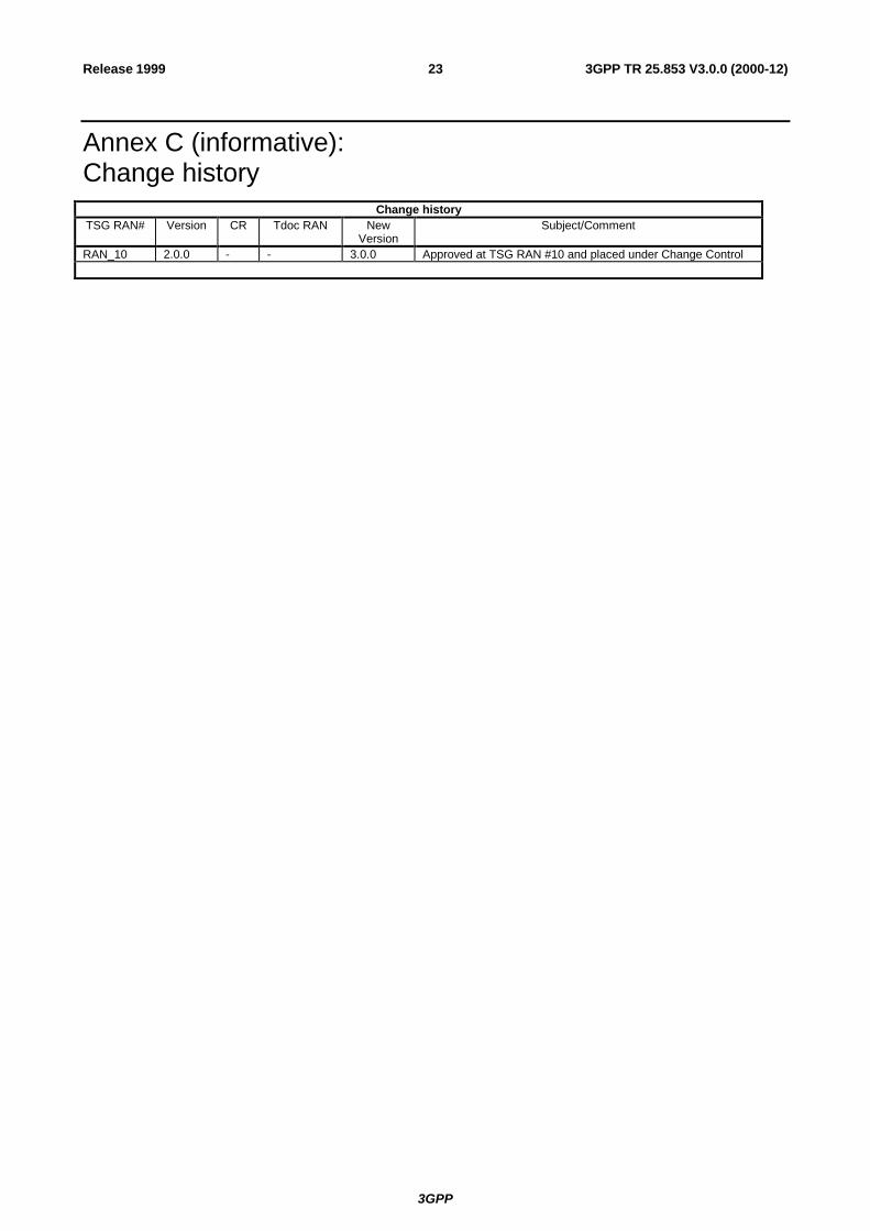
Annex C (informative): Change history
Change history TSG RAN# Version CR Tdoc RAN New
Version Subject/Comment
RAN_10 2.0.0 - - 3.0.0 Approved at TSG RAN #10 and placed under Change Control