technical report - 株式会社qt · 6.1.4.1 ue based solution ... this technical report has been...
TRANSCRIPT
3GPP TR 23.898 V7.0.0 (2005-03)Technical Report
3rd Generation Partnership Project;Technical Specification Group Services and System Aspects;
Access Class Barring and Overload Protection; (Release 7)
GLOBAL SYSTEM FOR MOBILE COMMUNICATIONS
R
The present document has been developed within the 3rd Generation Partnership Project (3GPP TM) and may be further elaborated for the purposes of 3GPP. The present document has not been subject to any approval process by the 3GPP Organizational Partners and shall not be implemented. This Specification is provided for future development work within 3GPP only. The Organizational Partners accept no liability for any use of this Specification.Specifications and reports for implementation of the 3GPP TM system should be obtained via the 3GPP Organizational Partners' Publications Offices.
3GPP
2Release 7 3GPP TR 23.898 V7.0.0 (2005-03)
Keywords UMTS, access, management
3GPP
Postal address
3GPP support office address 650 Route des Lucioles - Sophia Antipolis
Valbonne - FRANCE Tel.: +33 4 92 94 42 00 Fax: +33 4 93 65 47 16
Internet http://www.3gpp.org
Copyright Notification
No part may be reproduced except as authorized by written permission. The copyright and the foregoing restriction extend to reproduction in all media.
© 2005, 3GPP Organizational Partners (ARIB, ATIS, CCSA, ETSI, TTA, TTC).
All rights reserved.

3GPP
3Release 7 3GPP TR 23.898 V7.0.0 (2005-03)
Contents Foreword ............................................................................................................................................................5 1 Scope ........................................................................................................................................................5 2 References ................................................................................................................................................5 3 Definitions, symbols and abbreviations ...................................................................................................6 3.1 Definitions ......................................................................................................................................................... 6 3.2 Abbreviations..................................................................................................................................................... 6 4 Congestion and Failure Scenarios ............................................................................................................6 4.1 MSC/VLR or SGSN Congestion or Failure....................................................................................................... 6 4.1.1 Use case for domain specific access control ................................................................................................ 6 4.1.2 IMS and "IMS with Circuit Switched Bearers"............................................................................................ 7 4.1.3 RRC connected mode DSAC ....................................................................................................................... 7 4.1.4 Restart following a failure............................................................................................................................ 7 4.1.5 SGSN failure and Gs interface ..................................................................................................................... 7 4.2 MGW and/or voice transit network overload or failure..................................................................................... 7 4.3 SS7 signalling network overload/failure............................................................................................................ 8 4.4 Terminating calls/events .................................................................................................................................... 8 4.5 HLR Overload/Failure ....................................................................................................................................... 9 4.6 GGSN Overload/Failure .................................................................................................................................... 9 4.7 Packet backbone (GTP-U or Gi) overload/failure ............................................................................................ 9 4.8 Wide area radio interface congestion causing RNC/BSC overload/failure........................................................ 9 4.9 Cell level congestion/access for emergency services......................................................................................... 9 4.10 Multiple RATs ................................................................................................................................................. 10 4.11 Intra-domain connection of Radio Access Network (RAN) nodes to multiple Core Network (CN) nodes
(Iu Flex) ........................................................................................................................................................... 10 4.12 Network Sharing.............................................................................................................................................. 10 4.13 Handover into overloaded areas....................................................................................................................... 10 4.14 MBMS point to point repair............................................................................................................................. 11 5 Functional Requirements........................................................................................................................11 5.1 General overview............................................................................................................................................. 11 5.2 Functional requirements for access control mechanisms. ................................................................................ 11 5.3 Additional requirements .................................................................................................................................. 12 6 Potential Technical Solutions.................................................................................................................12 6.1 Domain Specific Access Class Barring approach............................................................................................ 12 6.1.1 Domain specific access restrictions (solution for requirement a)............................................................... 13 6.1.2 Handling UEs/MSs in connected mode (requirement b)............................................................................ 13 6.1.2.1 Handling of UEs/MSs with dedicated channels (CELL_DCH)............................................................ 15 6.1.2.2 Handling of existing signalling connection with assigned radio resources .......................................... 15 6.1.2.3 Handling of cases where DRNC and SRNC are connected to different CN nodes .............................. 16 6.1.2.4 Handling UEs that missed ACR information changes.......................................................................... 16 6.1.3 Domain Specific Access Control with Iu-flex (requirement a, i, l)............................................................ 16 6.1.4 PS Domain Specific Access Restriction and Gs Interface (requirement j)................................................. 17 6.1.4.1 UE based solution................................................................................................................................. 17 6.1.4.2 Network Operation Mode change (NMO change)................................................................................ 18 6.1.4.3 Preferred Solution................................................................................................................................. 18 6.1.5 Successive removal of access class (solution for requirement c) ............................................................... 19 6.2 Service Specific Access Class Barring approach............................................................................................. 19 6.2.1 Indication of SSACB.................................................................................................................................. 19 6.2.2 Realisation of SSACB in NAS................................................................................................................... 19 6.3 Handling overload situations by alternative solutions ..................................................................................... 20 6.3.1 RNC/BSC Overload (requirements d)........................................................................................................ 20 6.3.2 Cell Level Congestion and Allowing SMS and Emergency Calls (requirements d) .................................. 20 6.3.3 SS7 Signalling Network Overload/Failure (requirement e) ....................................................................... 20 6.3.4 Overload Protection from Terminating Calls/Events (requirement f) ........................................................ 20
3GPP
4Release 7 3GPP TR 23.898 V7.0.0 (2005-03)
6.3.5 Overload Protection from Packet backbone (GTP-U or Gi) overload/failure (requirement h) .................. 21 6.4 O&M Guidance ............................................................................................................................................... 21 6.4.1 Node Specific Access Control (requirement i, l)........................................................................................ 21 7 Conclusion..............................................................................................................................................21
Annex A (informative): Interlayer primitives within the UE .............................................................22
Annex B (informative): Improvements to prevent/delay automatic re-establishment attempts (requirement g) ..............................................................................................24
B.1 Classification of exiting GPRS/SMS specific cause value......................................................................... 24 B.2 Duration of wait timer and other configurations within MT ...................................................................... 25
Annex C (informative): Combination of Access Class Control ..........................................................25
Annex D: Change history .....................................................................................................................27
3GPP
5Release 7 3GPP TR 23.898 V7.0.0 (2005-03)
Foreword This Technical Report has been produced by the 3rd Generation Partnership Project (3GPP).
The contents of the present document are subject to continuing work within the TSG and may change following formal TSG approval. Should the TSG modify the contents of the present document, it will be re-released by the TSG with an identifying change of release date and an increase in version number as follows:
Version x.y.z
where:
x the first digit:
1 presented to TSG for information;
2 presented to TSG for approval;
3 or greater indicates TSG approved document under change control.
y the second digit is incremented for all changes of substance, i.e. technical enhancements, corrections, updates, etc.
z the third digit is incremented when editorial only changes have been incorporated in the document.
1 Scope The present document studies 3GPP system enhancements e.g. CS or PS domain specific access control to cope with several network overload and failure situations. This feasibility study also identifies the potential technical solutions for UTRAN and GERAN access control and overload protection.
Clause 4 reviews the various congestion and node failure scenarios: these will be used to derive any new functional requirements.
Clause 5 identifies the new functional requirements.
Clause 6 contains a presentation of the potential technical solutions.
Clause 7 conclusion.
2 References The following documents contain provisions, which, through reference in this text, constitute provisions of the present document.
• References are either specific (identified by date of publication, edition number, version number, etc.) or non-specific.
• For a specific reference, subsequent revisions do not apply.
• For a non-specific reference, the latest version applies. In the case of a reference to a 3GPP document (including a GSM document), a non-specific reference implicitly refers to the latest version of that document in the same Release as the present document.
[1] 3GPP TR 21.905: "Vocabulary for 3GPP Specifications".
[2] 3GPP TS 22.011: "Service accessibility".
[3] 3GPP TS 25.331: "Radio Resource Control (RRC) Protocol Specification".

3GPP
6Release 7 3GPP TR 23.898 V7.0.0 (2005-03)
[4] 3GPP TS 23.236: "Intra-domain connection of Radio Access Network (RAN) nodes to multiple Core Network (CN) nodes".
[5] 3GPP TS 22.101: "Service aspects; Service principles".
[6] 3GPP TS 24.008: "Mobile radio interface Layer 3 specification".
[7] 3GPP TS 23.246: "Multimedia Broadcast/Multicast Service (MBMS) ".
[8] 3GPP TS 23.205 "Bearer-independent circuit-switched core network".
3 Definitions, symbols and abbreviations
3.1 Definitions For the purposes of the present document, the [following] terms and definitions apply.
Domain Specific Access Control: Access control functionality for access barring in either domain (i.e. CS domain or PS domain).
CS domain Call Control Access Control: Access Class Restriction that can be used to limit CS domain Call Control accesses while permitting other Connection Management (e.g. SMS) and Mobility Management activity to the CS domain.
3.2 Abbreviations For the purposes of the present document, the following abbreviations apply. Additional applicable abbreviations can be found in 3GPP TR 21.905 [1].
DSAC Domain Specific Access Control
DSACR Domain Specific Access Control Restriction
4 Congestion and Failure Scenarios Congestion and failure scenarios are identified to help determine the functional requirements for any improvements or enhancements to the current specifications.
4.1 MSC/VLR or SGSN Congestion or Failure
4.1.1 Use case for domain specific access control When external disasters (e.g. earthquakes) or unusual events (e.g. London’s New Year’s day celebrations) affect a large area, CS voice calls are likely to increase greatly. In this situation, if MSC/VLR congestion happens then CS calls should be restricted. While some overload situations can be handled by the MSC rejecting call setup attempts, more severe overload situations need to be handled without impact on the MSC. In these situations, the operator can cause the BSC/RNC to apply access class barring.
However, applying the current access class barring mechanism will restrict both CS calls and PS sessions. This is undesirable and hence it would be useful to have a mechanism to restrict CS calls while permitting PS sessions.
Other situations can also be imagined where it will be useful to restrict PS sessions while permitting CS calls. Potential technical solutions for Domain Specific Access Control (DSAC) are discussed later in this TR.
3GPP
7Release 7 3GPP TR 23.898 V7.0.0 (2005-03)
4.1.2 IMS and "IMS with Circuit Switched Bearers" In the future, voice calls may be IMS based and use the PS domain (or for “IMS with Circuit Switched Bearers” both PS and CS domains). If the vast majority of voice and data traffic is in the PS domain, then DSAC does not add much benefit, but, neither does it cause any harm.
For the case of “IMS with circuit switched bearers”, it seems important that the RNC/BSC does not bar totally different access classes in the PS and CS domain.
Example: if the BSC needs to block 20% of PS traffic and 40% of CS traffic:
it should not bar, say, AC = 0, 1 for PS and AC =2,3,4,5 for CS;
instead, it should bar, say, AC = 6,7 for PS and AC = 6,7,8,9 for CS.
Note that the above recommendation appears to be the one that is most easily backward compatible.
4.1.3 RRC connected mode DSAC Both UMTS and GSM access class control only apply in idle mode. Hence, in UMTS, Access Class barring does not currently apply to mobiles that are in CELL_DCH, CELL_FACH, CELL_PCH or URA_PCH states.
It may be fairly straightforward to add Access Class Barring functionality to RRC connected mobiles that are not in the CELL_DCH state. For mobiles in CELL_DCH state it can be questioned whether CS domain access control is needed.
However, if CELL_DCH control is not provided then, during a disaster when the CS domain is barred but the PS domain is not barred, some customers will discover that they can make voice calls “provided they send an MMS/read an email just before dialling”. Following this event, this information will be passed on to everyone else, and, at the next disaster, virtually everyone will be using this technique to avoid having their calls blocked.
Hence solutions for “RRC connected mode access control” are needed for all sub-states (and need to correctly permit access to users with ‘special’ access classes).
4.1.4 Restart following a failure Following an outage, it is important to gradually increase the traffic on the restarting node, otherwise it is liable to fail again.
One method by which this can be achieved is to remove the access class barring by one Access Class at a time.
If both SGSN and MSC have failed (e.g. fire at a switch site), the operator may need to reconnect the MSC and SGSN at different times. If, say, the MSC has been reconnected successfully, it will be disruptive if the CS voice traffic has to be again barred in order to reconnect the SGSN.
This seems to lead to a requirement for the access class barring for PS and CS domains to be removed independently so that the traffic in the PS and CS domains can be independently ramped up.
4.1.5 SGSN failure and Gs interface When the network is using Network Mode of Operation 1 and the SGSN fails, it will be useful if mobiles can continue with CS domain operation.
Solutions for this issue need to ensure that they do not overload the MSC with, for example, location updates if PS domain access control is invoked.
Ideally, solutions should also permit mobile terminating calls to work during an SGSN failure.
4.2 MGW and/or voice transit network overload or failure With the release 4 MSC-Server and Media Gate Way architecture it is possible that the MGW can fail but the MSC-Server can still be operational. In such a situation it is very important that the mobility management signalling still functions and that SMS and PS domain traffic can still be handled.
3GPP
8Release 7 3GPP TR 23.898 V7.0.0 (2005-03)
While some overload situations can be handled by the MSC-server rejecting call setup attempts, more severe overload situations need to be handled without impact on the MSC, e.g. by the use of access class barring.
According to the current 3GPP TS 23.205 [8], one MSC Server can access multiple MGWs in operational situations, then a single MGW failure should be less of a problem.
If in operational situations, only one MGW is available, then it is useful to limit CS domain Call Control accesses while permitting other Connection Management (e.g. SMS) and Mobility Management activities. However, typically signalling traffic is routed via the MGW to the MSC-Server. Consequently, when only one MGW is available and the MGW or the transit network fails the MSC-Server will not receive signalling messages and is also not overloaded.
4.3 SS7 signalling network overload/failure There are instances where the SS7 network between the MSC/SGSNs and HLRs and/or SMSCs can become overloaded and/or fail while the voice transit network remains operational.
When there are problems on the visited MSC/SGSN to HLR connection, location area updates and routeing area updates could be rejected by the MSC/SGSN with an appropriate error cause (e.g. #17 Network Failure). After 4/5 attempts, the mobile then delays retrying for a long period (T3212). These techniques appear suitable for handling the MM and GMM signalling.
Each SMS probably uses very similar MSC processor capacity as a call set up attempt. Given the large volumes of SMS traffic that can be generated, and potentially automatically resubmitted following a delivery failure, it seems to be useful to try and provide overload control for SMS traffic in a manner that does not load the MSC but which permits voice calls to continue. The use of Reject messages with cause values and wait timers that delay the mobile from re-attempting SMS transfer could be useful.
An MSC typically processes all updates/calls/SMSs as long as not overloaded. When the MSC processing capacity is used up to a certain level the MSC reaches overload status, which may trigger alarms or overload control messages to other network entities. It may take considerable effort within the MSC to isolate the source of the SS7 overload and to signal or generate alarms indicating the overload reason, e.g. update, call control or SMS traffic, to allow for specific access class barring. Furthermore it should be noted that SS7 overload handling on signalling networks doesn’t allow for such a separation.
Significant amounts of SMS traffic can be generated by SMSCs that are not within the VMSC/V-SGSN operator’s control. This however cannot be solved by controlling UEs. Countermeasures by the network are needed, e.g. SS7 policing or overload control.
4.4 Terminating calls/events The current core specifications (and GSM test cases) make it clear that a mobile shall not respond to paging if its access class is barred.
However, for mobile terminating calls and SMSs, a large quantity of network processing has been completed prior to paging the mobile. If access class barring then prevents the mobile from responding, all this core network processing will have been wasted. While the core network may have techniques for load shedding that reduce the load near the source of the traffic, this does not resolve radio congestion issues at the A party.
Typically, it takes the B party’s MSC quite a long time (e.g. 8 to 25 seconds) to determine that the mobile has not responded to paging, and, in the case of mobile to mobile calls, this means that a traffic channel has been wasted on the A party’s radio interface. Further, the reaction of the A party to this situation is that they frequently redial, thus causing extra network load. Any diversion of the call to a voice mail platform can lead to both the A party and the voice mail platform attempting (repeatedly) to contact the B party.
This is sub-optimal and it would be preferable if the operator could control whether or not the mobile was permitted (required) to respond to the CS domain page. Alternatively, the mobiles are always allowed to respond to paging and the network drops terminating events before paging in case of overload.
The need for separate incoming/outgoing access control in the PS domain is currently less clear. However, with the potential for all voice traffic to migrate to IMS, it seems logical to provide the PS domain with similar capability.

3GPP
9Release 7 3GPP TR 23.898 V7.0.0 (2005-03)
4.5 HLR Overload/Failure The subscribers using one MSC (or SGSN) are normally distributed across multiple HLRs. Existing LA and RA Update reject causes and MM/GMM procedures can be used to ‘back off’ mobiles linked to a failed HLR. Hence, there does not seem to be a need to enhance the Access Class Barring procedures to handle HLR problems.
4.6 GGSN Overload/Failure Normally many GGSNs are reachable from one SGSN, and, frequently more than one GGSN is associated with an APN. Hence, there does not seem to be a need to enhance the Access Class Barring procedures to handle GGSN problems.
If the SGSN knows that the GGSN is unreachable, or, if the GGSN does not respond to the attempt to activate the PDP context, then the SGSN needs to be able to prevent the mobile from automatically re-attempting to activate the PDP context.
4.7 Packet backbone (GTP-U or Gi) overload/failure In this situation it will be necessary to reduce the user plane traffic without loading the SGSN.
If the GMM signalling is barred at the same time as the user plane traffic, there is likely to be an increased peak in GMM signalling load when the barring is removed. This load peak might cause other forms of instability, and, it is important that user-plane overload does not subsequently lead to signalling overload. Hence it will be very useful to keep GMM signalling active (especially if the network is using NMO=1/Gs interface) during a packet backbone overload/failure.
As SMS traffic does not load the packet backbone, there is no reason to restrict SMS just because the packet backbone has overloaded. Conversely, the packet backbone might have been overloaded because of a peak in “voice IMS traffic” or other PS data relating to an emergency: during such a situation it will be useful to permit the radio efficient SMS traffic to continue and permit person to person communication. Hence it will be important to keep SMS traffic flowing while overload in the packet backbone occurs.
Mechanisms are also desirable to reduce load before a severe overload occurs. It may be useful to give GTP signalling packets priority over most user data packet to avoid signalling overload in case of packet backbone overload. User data packets that can not be transferred due to overload can be discarded.
Editor’s note: in UMTS, some control can be achieved by the SGSN rejecting new Iu interface Service Requests with service type = data. In GSM A/Gb mode, the SGSN does not have this capability.
4.8 Wide area radio interface congestion causing RNC/BSC overload/failure
The existing access class barring procedures provide functionality to control users in idle mode, however extra functionality is needed to control RRC connected mode mobiles (e.g. those in URA_PCH state).
A separate issue is that during an emergency situation, customers will wish to communicate the fact that they are OK to their friends and relatives. One of the most radio efficient ways of communicating is via SMS, and within GSM, SMS traffic can frequently be handled without impacting call control signalling. Hence, it may be useful to provide separate access control for SMS compared to CS-voice calls and PS domain access. Or, it may be useful to transfer SMS on PS domain when emergency situations typically cause overload for the CS domain.
4.9 Cell level congestion/access for emergency services During, for example a traffic jam, GSM cells frequently have significant blocking of voice calls. This is not a problem unless the emergency services need to use that cell for their voice calls. In this case, existing access class barring functionality is used.
3GPP
10Release 7 3GPP TR 23.898 V7.0.0 (2005-03)
However, within GSM, it is noticeable that cells that are under intense voice call overload are still able to carry substantial amounts of SMS traffic. Hence a useful enhancement to GSM might be to maintain SMS transfer when access class barring for voice calls is invoked. It may be useful to transfer SMS on PS domain.
Whether of not UTRAN exhibits similar properties, as GSM is FFS.
4.10 Multiple RATs Currently the specifications state that mobiles shall not reselect another cell just because the Access Class Barring bits have been set on the serving cell. With overlaid 2G and 3G coverage, it is worth considering whether control of Radio Access Technology change should be provided in RNC or BSC overload situations. However, care is needed to ensure that any sudden change in RAT does not lead to a peak of LA/RA updates that cause harm to the new RAT’s core network nodes.
No changes to the access class barring functionality seems necessary because ‘cell barring’ can be used to force mobiles away from one RAT to another one.
4.11 Intra-domain connection of Radio Access Network (RAN) nodes to multiple Core Network (CN) nodes (Iu Flex)
Enhancements to Access Class barring need to take into account this functionality. Overload within one CN node could lead to (manual) adjustment of the BSC/RNC routing tables, however, great care is needed when doing this to ensure that this does not overload other CN nodes and cause multiple node failures.
When the CN nodes are optimally (heavily) loaded, failure of one CN node will prevent its load being moved onto other CN nodes. When the node that failed is brought back into service, its load needs to be restored gradually. This implies that the overload control should be made applicable only to the mobiles registered on the recovering node.
Iu flex permits 2 to more than 100 CN nodes to be connected to one RAN node.
4.12 Network Sharing The requirements for shared networks will be similar to those in clause 4.11, except that there is less scope for sharing the load from one network operator to their competitor. Operators who use network sharing should not be prevented from using Iu flex functionality. Overall, however, it will be important that one competitor’s network problem does not restrict the traffic on the other competitor.
The standards for Iu flex based network sharing permit 2 to 5 CN operators to share one RAN node.
4.13 Handover into overloaded areas Currently, access class barring has no impact on the network controlled handover of traffic into a cell which has some of its access classes barred. Given that the network has visibility of the load situation in serving and target cells, and that the network can release the connection to reduce load, this situation seems satisfactory.
However, with the current UTRAN design, the network will not be able to control traffic following RRC connected mode cell reselections made by the mobile in CELL_FACH, CELL_PCH and URA_PCH states.
Because the mobile is not actively transferring data in these CELL_PCH and URA_PCH states, this seems to lead to a requirement for the mobile to obey the serving cell’s Access Class barring in these states. Conversely, it can be argued that it would be beneficial for the UTRAN mobility management machine to be maintained and to permit the Cell Update message to be sent when the mobile leaves the old URA (or cell in the CELL_PCH case).
In the CELL_FACH state, should the mobile’s data transfer be broken automatically when it performs ‘mobile controlled handover’ into a cell where its Access Class is barred? This will probably vary on a case by case basis.
This seems to require independent Access Class Barring control for “access following mobile controlled handover” to that for “mobile initiated traffic” in the CELL_FACH, CELL_PCH and URA_PCH states.

3GPP
11Release 7 3GPP TR 23.898 V7.0.0 (2005-03)
4.14 MBMS point to point repair The MBMS point to point repair service might impose peaks of extra load on a cell (and other parts of the network). In the case, there is one way for this load to be distributed is for the BM-SC to distribute to each UE, at activation time, one or more server addresses (from a group of addresses), along with parameter(s) that are used to generate a random time dispersion of the requests.
Note: The above way is specified in 3GPP TS23.246 [7].
5 Functional Requirements
5.1 General overview The existing Access Control mechanisms are specified in 3GPP TS 22.011, 3GPP TS 25.331, 3GPP TS 44.018 and 44.060.
Within UTRAN, the Access Class barring information is sent in the Cell Access Restriction IE which is sent in SIB 3 and SIB 4.
Within GERAN, the Access Class barring information is sent:
- on the BCCH in the RACH Control Parameters IE sent in SYSTEM INFORMATION TYPE 1, 2, 2bis, 3, and 4 messages, and,
- on the PBCCH/PCCCH in the PRACH Control Parameters IE in the Packet System Information Type 1 and Packet PRACH Parameters messages.
The current access control is limited to UEs in idle mode. It has been found suitable for cell level and RNC/BSC level congestion control. However, it is not optimised for congestion affecting only one CN domain because the system information does not distinguish between CS or PS domains (except if the GSM PBCCH is in use).
5.2 Functional requirements for access control mechanisms. One key requirement is that the mechanisms used to control overload do not require extra processing by the node that is overloaded. In general, this requirement could be met by BSC/RNC O+M commands being used to control the settings of any Extended Access Class Barring parameters. The use of extensions to the A/Iu interface Overload messages requires further study.
To control or restrict access from UEs to a specific domain, it is natural to extend the existing access control mechanism specified in 3GPP TS 22.011 and 3GPP TS 25.331, 44.018, 44.060, as well as to consider other mechanisms.
From the requirements in clause 4, the following functional requirements can be derived:
a) (from 4.1.1) the capability to reduce load on the CS (or PS) domain without reducing load on the other domain;
b) (from 4.1.3) the need for mechanisms by which access to the CS domain from mobiles that are in PMM connected state can be controlled;
c) (from 4.1.4) the need for mechanisms that can gradually increase the permitted access to one CN domain independently of the overload setting on the other CN domain;
d) (from 4.8 and 4.9) the capability to limit CS domain Call Control accesses while permitting SMS;
e) (from 4.3) the need for extra 24.008 and/or 24.011 Session Management cause values and/or procedures to delay the mobile re-attempting SMS transfer;
f) (from 4.4) the capability to overload control terminating events independent from mobile originating traffic;
g) (from 4.6 and 4.7) the need for extra 24.008 Session Management cause values and/or procedures to delay the mobile re-attempting PDP context activation, and, the need for PS domain “automatic calling repeat call attempt restrictions” (similar to those in Annex E of 22.001) to be specified;
3GPP
12Release 7 3GPP TR 23.898 V7.0.0 (2005-03)
h) (from 4.7) the capability to limit PS domain user data traffic while permitting Session Management, GMM and SMS activity.
i) (from 4.11) RNC/BSC functionality is needed to handle overload of CN nodes when “intra-domain connection of Radio Access Network (RAN) nodes to multiple Core Network (CN) nodes” is in use. Typically this should permit preventing only the transactions related to the overloaded CN node(s).
j) (from 4.1.5) methods should be documented for handling SGSN failure when the network is using NMO=1 (Gs interface).
k) (from 4.13) the capability to control “access following mobile controlled handover” independently to that for “mobile initiated traffic” in the CELL_FACH, CELL_PCH and URA_PCH states.
l) (from 4.12) RNC functionality is needed to handle overload within only one of the multiple competing operator’s core networks.
Potential technical solutions for these 5 groups of functional requirements are discussed in clause 6.
5.3 Additional requirements At least the following additional aspects should be considered:
1) the speed with which mobiles should react to changes in Access Class barring.
In GSM, idle mode mobiles are required to re-read the serving cell’s System Information every [30] seconds. They are supposed to check the Access Class barring bits prior to every access attempt, however, it is not certain that mobiles actually do this. Hence GSM mobiles detect changes in the Access Class barring bits with an average delay of 15 seconds. This appears to be sufficient. If it is insufficient, mobiles can be forced to “immediately” re-read the Access Class barring bits by setting the ‘page mode’ to “paging-reorganisation” in all the paging messages.
In UTRAN, existing UTRAN procedures such as paging are believed to be sufficient for notification of the change in any access class barring status.
2) Broadcast Channel Capacity
Extensions to the existing access class barring functionality need to take into account the amount of capacity available on the broadcast channels. Particular care may be needed when designing solutions for multiple shared networks and networks using “Iu-flex”.
6 Potential Technical Solutions The potential solutions that may satisfy the requirements in clause 5, consist of two distinct approaches:
• The first one consists in Domain Specific Access Control barring approach. (clause 6.1)
• The other, consists in preventing or delaying the automatic re-establishment attempts.(Annex B)
• The third one consists in service specific access class barring approach.(clause 6.2)
• The last one consists in how to handle overload situations that have alternative solutions with and without above approaches. (clause 6.3)
Clause 6.4 further includes best practice guidance for some miscellaneous issues.
6.1 Domain Specific Access Class Barring approach This consists of:
1) Extending the existing system information in SIB3, SIB 4, and PSI 1, and adding new parameters to messages on the extended BCCH (e.g. in System Information 7 and 8).
3GPP
13Release 7 3GPP TR 23.898 V7.0.0 (2005-03)
2) Extending the requirements of the UE so that the UE should also apply Domain Specific access control information when it is in RRC/RR connected mode.
3) Ensuring that the RNC has a good co-ordination when using a CN domain specific Access Control together with Iu-flex.
4) Enabling Domain Specific Access Control to be applied for SGSN overload/failure when the Gs interface is implemented.
5) Enabling a staggered lifting of Access Restrictions.
6.1.1 Domain specific access restrictions (solution for requirement a) Taking advantage of the currently available procedures, the system information broadcast by RNC is extended so that access class barring list can be specified to allow a more accurate restriction of only the service/access types that would worsen an overload problem.
Such a mechanism will significantly reduce the impact on idle mode users who wish to access the network for other service-related reasons.
Example:
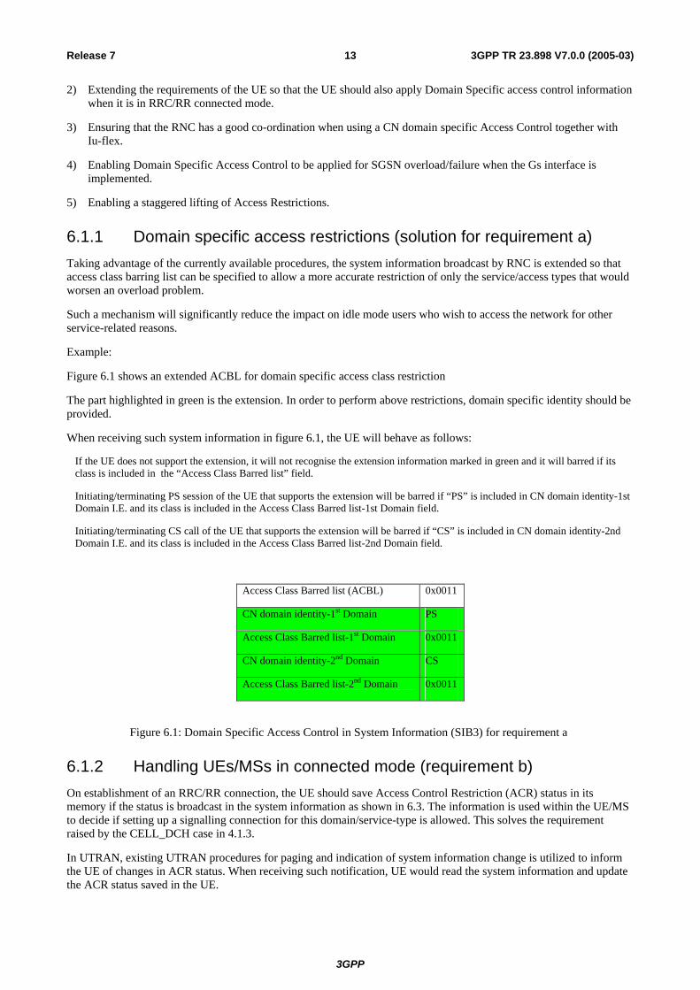
Figure 6.1 shows an extended ACBL for domain specific access class restriction
The part highlighted in green is the extension. In order to perform above restrictions, domain specific identity should be provided.
When receiving such system information in figure 6.1, the UE will behave as follows:
If the UE does not support the extension, it will not recognise the extension information marked in green and it will barred if its class is included in the “Access Class Barred list” field.
Initiating/terminating PS session of the UE that supports the extension will be barred if “PS” is included in CN domain identity-1st Domain I.E. and its class is included in the Access Class Barred list-1st Domain field.
Initiating/terminating CS call of the UE that supports the extension will be barred if “CS” is included in CN domain identity-2nd Domain I.E. and its class is included in the Access Class Barred list-2nd Domain field.
Access Class Barred list (ACBL) 0x0011
CN domain identity-1st Domain PS
Access Class Barred list-1st Domain 0x0011
CN domain identity-2nd Domain CS
Access Class Barred list-2nd Domain 0x0011
Figure 6.1: Domain Specific Access Control in System Information (SIB3) for requirement a
6.1.2 Handling UEs/MSs in connected mode (requirement b) On establishment of an RRC/RR connection, the UE should save Access Control Restriction (ACR) status in its memory if the status is broadcast in the system information as shown in 6.3. The information is used within the UE/MS to decide if setting up a signalling connection for this domain/service-type is allowed. This solves the requirement raised by the CELL_DCH case in 4.1.3.
In UTRAN, existing UTRAN procedures for paging and indication of system information change is utilized to inform the UE of changes in ACR status. When receiving such notification, UE would read the system information and update the ACR status saved in the UE.
3GPP
14Release 7 3GPP TR 23.898 V7.0.0 (2005-03)
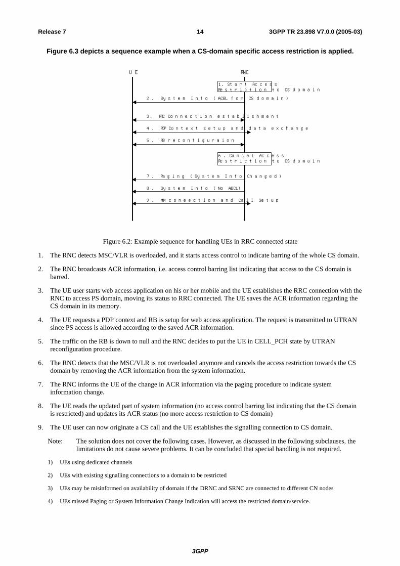
Figure 6.3 depicts a sequence example when a CS-domain specific access restriction is applied.
Figure 6.2: Example sequence for handling UEs in RRC connected state
1. The RNC detects MSC/VLR is overloaded, and it starts access control to indicate barring of the whole CS domain.
2. The RNC broadcasts ACR information, i.e. access control barring list indicating that access to the CS domain is barred.
3. The UE user starts web access application on his or her mobile and the UE establishes the RRC connection with the RNC to access PS domain, moving its status to RRC connected. The UE saves the ACR information regarding the CS domain in its memory.
4. The UE requests a PDP context and RB is setup for web access application. The request is transmitted to UTRAN since PS access is allowed according to the saved ACR information.
5. The traffic on the RB is down to null and the RNC decides to put the UE in CELL_PCH state by UTRAN reconfiguration procedure.
6. The RNC detects that the MSC/VLR is not overloaded anymore and cancels the access restriction towards the CS domain by removing the ACR information from the system information.
7. The RNC informs the UE of the change in ACR information via the paging procedure to indicate system information change.
8. The UE reads the updated part of system information (no access control barring list indicating that the CS domain is restricted) and updates its ACR status (no more access restriction to CS domain)
9. The UE user can now originate a CS call and the UE establishes the signalling connection to CS domain.
Note: The solution does not cover the following cases. However, as discussed in the following subclauses, the limitations do not cause severe problems. It can be concluded that special handling is not required.
1) UEs using dedicated channels
2) UEs with existing signalling connections to a domain to be restricted
3) UEs may be misinformed on availability of domain if the DRNC and SRNC are connected to different CN nodes
4) UEs missed Paging or System Information Change Indication will access the restricted domain/service.
2. System Info (ACBL for CS domain)
3. RRC Connection establishment
4. PDP Context setup and data exchange
5. RB reconfiguraion
7. Paging (System Info Changed)
8. System Info (No ABCL)
9. MM coneection and Call Setup
UE RNC
1. Start AccessRestriction to CS domain
6. Cancel AccessRestriction to CS domain

3GPP
15Release 7 3GPP TR 23.898 V7.0.0 (2005-03)
6.1.2.1 Handling of UEs/MSs with dedicated channels (CELL_DCH)
Handling of UEs/MSs with dedicated channels is not necessary based on the analysis below.
1) Handling of UEs/MSs engaging in CS activity when the entity in CS domain becomes restricted. If a new call setup from idle mode UEs are prevented, it can be seen that congested situation would be mitigated quickly. Refer to the note below.
Note: According to the year 2002 statistics published by Japanese Ministry of Public Management, Home Affairs, Posts and Telecommunications, the average duration of mobile originating CS calls is 122 seconds and CS calls less than 30 and 60 seconds account for 40% and 60% of all calls, respectively.
2) UTRAN only: Handling of UEs using dedicated channels for PS activity when entity in PS domain becomes restricted Most PS services provisioned have interactive nature. It is, therefore, expected that duration of staying dedicated mode is usually short. If there is not enough traffic, the RNC will switch the UE from dedicated to common channel state. Once the UE is put in the common channel state, then it can be notified of ACR changes by the proposed method shown above. It should continue to abide by this if it returns to dedicated state. It is also considered not likely that the UE remaining in CELL_DCH would generate severe Iu signalling or SGSN processing load increase by requesting secondary PDP contexts or other PDP contexts.
3) Handling of UEs/MSs using dedicated channels for not restricted domain. The proportion of UEs using a dedicated channel over all UEs in MSC or SGSN area is, normally, considered to be low, particularly less than 5 %. Moreover the duration staying dedicated mode is considered as short based on the description 1) and 2) above. Therefore it is not likely that those UEs generate severe signalling load to the restricted domain.
6.1.2.2 Handling of existing signalling connection with assigned radio resources
A signalling connection is established to a domain in order to request CS/PS services or NAS signalling transactions such as RAU and SMS. In case of NAS signalling, when the requested transaction is completed the UE goes to IDLE state unless there is pending signalling needs, and will read the access control information if broadcast. Generally such signalling transaction is processed in a very short period. Therefore it seems safe to leave the signalling connection for NAS signalling transactions without any particular care in overload/failure situation.
However, if there exists a signalling connection with radio resources assigned for PS services, unwanted traffic increase may occur. The UE in URA_PCH state, for example, may suddenly become active and generate a large amount of traffic and worsen the situation. In other case, the UE may request more radio resources by using the existing signalling connection. We are going to take a look at the two cases and discuss suitable measures to be taken.
1) Sudden traffic increase on the existing radio bearers
The case could become a serious issue in the situation mentioned in the clause 4.1.5, 4.7, 4.8 and 4.9. To prohibit the UE from generating unacceptable traffic increase by using existing RBs, an indication could be sent to the UE in a dedicated message or system information. This requires RRC protocol to be enhanced. Moreover, it has large impacts to the UE implementation.
Another way forward is to rely on the exiting traffic volume measurement capability. The RNC measures the DL and UL traffic volume to and from the UE. It is also aware of the situation of the service cell of the UE. Therefore if the traffic increase is unacceptable, the RNC can release the RRC connection. On the RRC connection release, the UE will read the system information, and realize that the access control restriction is active.
Based on the discussion above, it seems that the currently available mechanisms and clever RNC implementation (release the RRC connection if the traffic reaches the certain threshold and if access control is active) should be sufficient.
Note that the discussion above can be applicable to the scenario described in the clause 4.13 (handover into the overloaded area) (Requirement k).
2) Traffic increase due to request for more radio resources on the signalling connection.
An instance of such case may be in a real-time/conversational service where UE requests for a secondary PDP context or modification of existing PDP context for more bandwidth.

3GPP
16Release 7 3GPP TR 23.898 V7.0.0 (2005-03)
To prohibit such new bearer assignments or modifications, a dedicated message could be sent from the RNC to the UE. This requires RRC protocol enhancement and impacts the UE and RNC implementation. Moreover, it may not be very effective since the RNC has to instruct all UEs with signalling connection, which may create other congestion or failure.
Another way forward is to rely on the existing or clever node implementation. In case of GTP-U/Gi interface overload/failure, number of retransmission of Create PDP Context Request may reach the threshold. In such case, SGSN returns activate secondary PDP context reject to the UE. In case of the radio network congestion, on the other hand, the RNC is aware of congestion status of the cell serving the UE. The RNC may reject the request for RAB assignment from the SGSN.
The behaviour shown above is already in the current standards and it is only performed on the UE request for RB setup or modification therefore less impact to the congestion/failure situation. If automatic calling repeat call attempt restrictions is made available in PS domain we can reduce the impact further.
In IMS, the aforementioned case 2) occur when UE with a signalling PDP context in URA_PCH requests for multimedia access. When the signalling PDP context is preserved, the UE goes to the idle state and will read the access control information if broadcast. The UE copies the access control information and acts on the information when it resumes the PDP context as described in 6.1.2.1.
Based on the discussion above, we propose that currently available mechanisms should be sufficient for handling existing signalling connection with assigned radio resources in overload or failure situation.
6.1.2.3 Handling of cases where DRNC and SRNC are connected to different CN nodes
There is a case where the UE may be misinformed on the availability of a domain/entity when the DRNC and SRNC are connected to different CN nodes. For example, when the DRNC is connected to a congested node and the SRNC is connected to a CN node with normal condition, then the UE will be unnecessarily put under access restriction toward the domain/entity.
The issue may be somewhat resolved by relocating UEs on boundary between RA and LA containing congested serving CN nodes.
Note: It is FFS to check if SRNC relocation applied to UEs on the boundary of RA/LA may cause any problems to the congested CN node.
6.1.2.4 Handling UEs that missed ACR information changes
If Paging or System Information Change Indication is not received, the UE may initiate Cell/URA update procedure or Initial Direct Transfer procedure for the access to the restricted domain. To handle such UE, the UTRAN procedures may be extended to indicate changes in system information. By setting appropriate repetition parameter in the procedures, however, probability of UEs missing the notification can be kept sufficiently low.
Therefore, the extensions to the existing RRC procedures may not be necessary.
Another possibility is for RNC to reject signalling connection request from the UE to the restricted domain. Such a mechanism would require the RNC to have knowledge of the UE’s access class in order that it did not prevent access to a UE from a non-restricted class. There is, however, no mechanism to prevent the UE to repeat the requests.
6.1.3 Domain Specific Access Control with Iu-flex (requirement a, i, l) In a network configuration using Iu-flex, if one MSC/VLR or SGSN in the pool indicate overload situations to the RNC, then the RNC routes initial NAS messages from UEs being served by an overloaded CN node to an available non-overloaded MSC/VLR or SGSN in the pool area. Consequently the UEs of the overloaded CN node(s) end up being served by non-overloaded MSC/VLRs or SGSNs in the pool area.
Further specification of this functionality is needed (e.g. use of CM Service Reject with cause “IMSI unknown in VLR” from the MSC or cause 9 from the SGSN.).
If multiple or all MSC/VLR or SGSN in the pool area indicate overload, the RNC may decide to use NRI specific access control. A consequence of this is that the NRIs for a CN node need to be allocated as a contiguous block.
3GPP
17Release 7 3GPP TR 23.898 V7.0.0 (2005-03)
Another alternative is that the RNC locally rejects or discards the Initial Direct Transfer message. Ultimately, this might result in RNC overload which could lead to Access Class barring for the whole RNC.
Note: a combination of re-routing and discarding initial DT may work well.
This RNC decision is implementation specific.
F.F.S: Verify that Iu-flex does not require any other additional access control functionality on the Uu interface compared to network configurations without Iu-flex, (that means without NRI specific access control).
Similar functionality can be used for network sharing, however, further examination is needed.
6.1.4 PS Domain Specific Access Restriction and Gs Interface (requirement j)
PS domain access restriction is applied as a result of the congestion and failure situations described in clause 4.
Under Network Operation Mode I, PS Domain Access Restriction prevents combined MM procedures to take place, which in turn may result in UEs becoming unreachable for mobile terminated CS services.
A solution should be provided to allow the UE to maintain its CS services despite the PS Domain restriction that is applied.
There are 2 possible solutions
1- A UE Based solution
2- A Network Operation mode change solution
6.1.4.1 UE based solution
This first solution introduces a new UE based procedure to maintain CS services when PS domain access class barring is applied.
This solution requires to introduce a new behaviour in the UE
The UE will react upon the received DSAC information (Access Class Barred List or ACBL) and will shift from Combined MM to Specific MM procedures, at the next periodic LA update or when the UE moves in another LA.
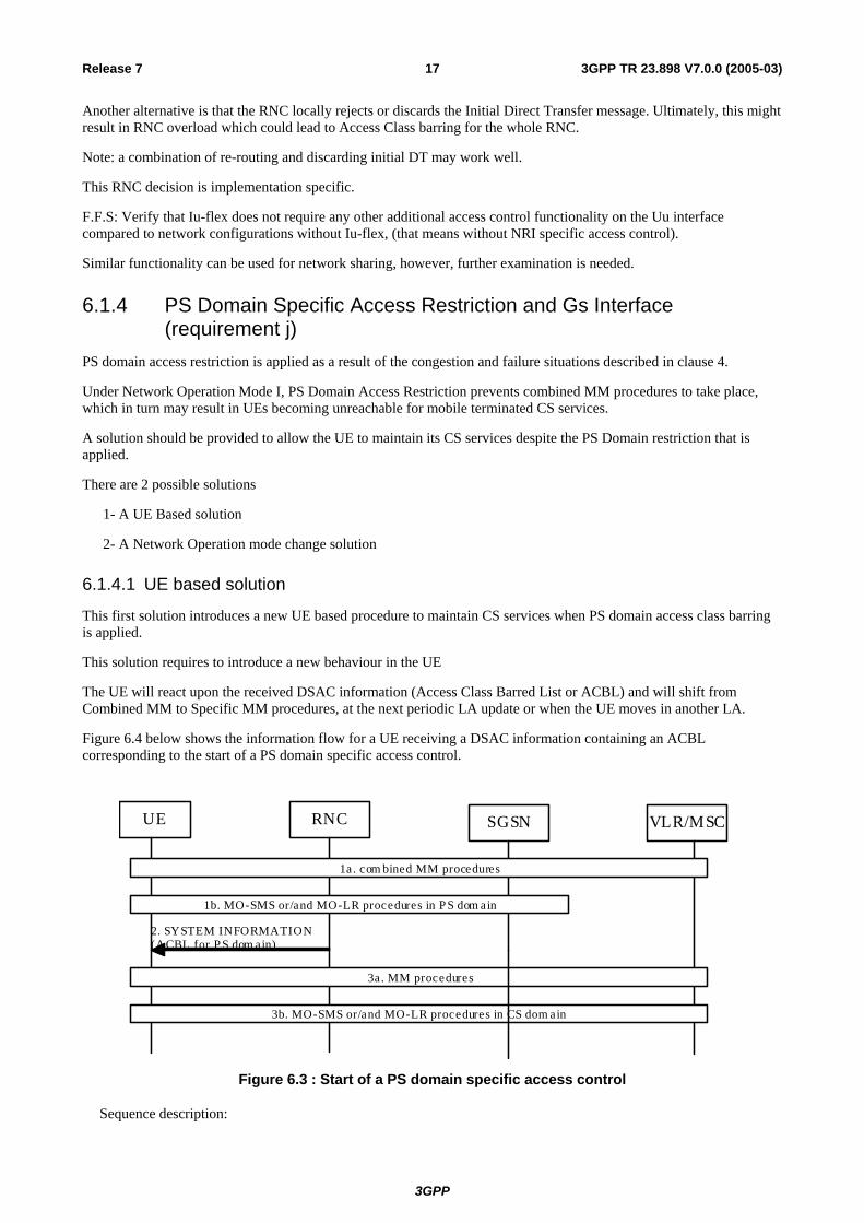
Figure 6.4 below shows the information flow for a UE receiving a DSAC information containing an ACBL corresponding to the start of a PS domain specific access control.
UE RNC
2. SYSTEM INFORMATION (ACBL for P S dom ain)
SGSN VLR/MSC
1a. com bined MM procedures
1b. MO-SMS or/and MO-LR procedures in P S dom ain
3a. MM procedures
3b. MO-SMS or/and MO-LR procedures in CS dom ain
Figure 6.3 : Start of a PS domain specific access control
Sequence description:
3GPP
18Release 7 3GPP TR 23.898 V7.0.0 (2005-03)
1. The network is in operation mode I before any congestion or failure
1a. UE performs combined MM procedures.
1b. The UE may perform MO-SMS and/or MO-LR procedures in PS domain.
2. The RNC detects SGSN overload or failure, then the RNC broadcasts system information with DSAC to the UE.
3. UE Behaviour during DSAC
3a. The UE stops performing combined MM procedures and starts performing specific MM procedure for CS domain, at the next periodic LA update or when the UE moves in another LA/RA.
3b. The UE immediately selects the CS domain if the UE needs to perform MO-SMS and/or MO-LR procedures.
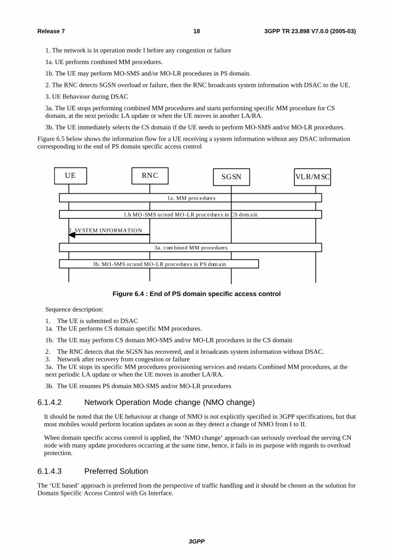
Figure 6.5 below shows the information flow for a UE receiving a system information without any DSAC information corresponding to the end of PS domain specific access control
UE RNC
2. SYSTEM INFORMATION
SGSN VLR/MSC
3a. com bined MM procedures
3b. MO-SMS or/and MO-LR procedures in P S dom ain
1a. MM procedures
1.b MO-SMS or/and MO-LR procedures in CS dom ain
Figure 6.4 : End of PS domain specific access control
Sequence description:
1. The UE is submitted to DSAC 1a. The UE performs CS domain specific MM procedures.
1b. The UE may perform CS domain MO-SMS and/or MO-LR procedures in the CS domain
2. The RNC detects that the SGSN has recovered, and it broadcasts system information without DSAC. 3. Network after recovery from congestion or failure 3a. The UE stops its specific MM procedures provisioning services and restarts Combined MM procedures, at the next periodic LA update or when the UE moves in another LA/RA.
3b. The UE resumes PS domain MO-SMS and/or MO-LR procedures
6.1.4.2 Network Operation Mode change (NMO change)
It should be noted that the UE behaviour at change of NMO is not explicitly specified in 3GPP specifications, but that most mobiles would perform location updates as soon as they detect a change of NMO from I to II.
When domain specific access control is applied, the ‘NMO change’ approach can seriously overload the serving CN node with many update procedures occurring at the same time, hence, it fails in its purpose with regards to overload protection.
6.1.4.3 Preferred Solution
The ‘UE based’ approach is preferred from the perspective of traffic handling and it should be chosen as the solution for Domain Specific Access Control with Gs Interface.
3GPP
19Release 7 3GPP TR 23.898 V7.0.0 (2005-03)
6.1.5 Successive removal of access class (solution for requirement c) By allocating independent Access class barring lists to the PS and CS domains, it is possible to control traffic by removing access classes within each list, one by one.
This allows for independent CN domain specific overload protection since traffic in the PS and CS domains can be increased independently by removing access class barring one access class at a time.
6.2 Service Specific Access Class Barring approach This clause consists in service specific access control class barring approach, corresponded to requirements d, e, f, and h. This approach impacts not only AS but also NAS functionality.
6.2.1 Indication of SSACB Service Specific Access Class Barring (SSACB) refers to the access control function to restrict UE access to CS calls, PS sessions and SMS. The access control function also allows paging response under the existing access class barring.
SSACB is indicated in the system information like DSAC approach in 6.1. The system information specifies an access class barred list and the type of SSACB, e.g. CS calls. When the RRC in the MS receives such indication, it checks if the access class of the MS is barred to the indicated service. If barred, the RRC notifies the upper layer as shown below.
1) CS domain Call Control Access Control The RRC notifies the CM sub-layer that the origination of CS calls is restricted. It also notifies the MM layer that responding paging for CS terminating calls is restricted. If the class 10 is barred then the RRC also notifies the CM sub-layer that origination of emergency calls is restricted.
2) Access Class Barring with Paging Response Permission The RRC notifies the CM sub-layer that the origination of CS calls is restricted. If the class 10 is barred then the RRC also notifies that originating an emergency call is restricted.
3) SMS Access Control The RRC notifies CM sub-layer that the origination of SMS access is restricted. Regarding MT-SMS, the MS should respond to the paging in order to avoid the re-transmission of MT-SMS.
4) PS Traffic Access Control The RRC notifies the CM sub-layer that activation of the PDP contexts is restricted. It also notifies the GMM layer that responding paging request for GPRS services is restricted.
When the system information indicates no SSACB, then the RRC notifies the upper layer that the restriction to the MS is no longer active.
6.2.2 Realisation of SSACB in NAS Upon the notification from RRC as described in 6.2.1, the NAS sets or clears variables which will be introduced, corresponding to the specific service access restriction. The NAS acts upon the variables as follows.
1) CS domain Call Control Access Control If origination of a conversational call is requested by the upper layer, the call control entity in the CM sub-layer checks the variable, "CS Call Restriction". If restricted, the CS call is rejected. If origination of an emergency call is requested by the upper layer, the call control entity in CM sub-layer checks the variable, "Emergency Call Restriction". If restricted, the emergency call is rejected. On reception of paging for CS services, the MM layer checks the variable "Paging Response to CS Services Restriction". If restricted, The MM layer ignores the paging indication.
2) Access Class Barring with Paging Response Permission If origination of a CS call is requested by the upper layer, the call control entity in the CM sub-layer checks the variable, "CS Call Restriction". If restricted, the conversational call is rejected. If origination of an emergency call is requested by the upper layer, the call control entity in CM sub-layer checks the variable, "Emergency Call Restriction". If restricted, the emergency call request is rejected.
3GPP
20Release 7 3GPP TR 23.898 V7.0.0 (2005-03)
3) SMS Access Control If MO-SMS is requested by the upper layer, the SMS or GSMS entity in the CM sub-layer checks the variable, "SMS restriction". If restricted, MO-SMS is rejected.
4) PS Traffic Access Control If PDP context activation is requested by the upper layer, the SM entity checks the variable, "PDP Context Activation Restriction". If restricted, activation of the PDP context is rejected. On reception of paging for GPRS services, the GMM layer checks the variable "Paging Response to GPRS Services Restriction". If restricted, The GMM layer ignores the paging indication.
6.3 Handling overload situations by alternative solutions This clause consists in how to handle overload situations that have alternative solutions, corresponding to requirements d, e, f, and h.
6.3.1 RNC/BSC Overload (requirements d) This situation is described in clause 4.8 as the wish to communicate by SMS in overload situations during emergency situations. Like described in clause 4.9 overload is anticipated rather for the CS domain because of many CS voice calls. DSAC allows to reduce CS domain traffic without impacting the PS domain. In this situation the UEs may transfer SMS over the PS domain.
DSAC seems sufficient to handle such situations.
6.3.2 Cell Level Congestion and Allowing SMS and Emergency Calls (requirements d)
GSM cells shall allow to transfer SMS even when blocked by CS voice calls. DSAC allows to reduce CS domain traffic without impacting the PS domain. In this situation the UEs may transfer SMS over the PS domain.
DSAC seems sufficient to handle such situations.
6.3.3 SS7 Signalling Network Overload/Failure (requirement e) There are instances where the SS7 network between the MSC/SGSNs and HLRs and/or SMSCs can become overloaded and/or fail while the voice transit network remains operational.
When there are problems on the visited MSC/SGSN to HLR connection, location area updates and routeing area updates could be rejected by the MSC/SGSN with an appropriate error cause (e.g. #17 Network Failure). After 4/5 attempts, the mobile then delays retrying for a long period (CS: T3212, PS: T3302). These techniques appear suitable for handling the MM and GMM signalling.
Each SMS probably uses very similar MSC processor capacity as a call set up attempt. Given the large volumes of SMS traffic that can be generated, and potentially automatically resubmitted following a delivery failure, it seems to be useful to try and provide overload control for SMS traffic in a manner that does not load the MSC but which permits voice calls to continue. The use of Reject messages with cause values and wait timers that delay the mobile from re-attempting SMS transfer could be useful. This approach is better than service specific access class barring approach. Annex B describes the cause values and wait timers.
6.3.4 Overload Protection from Terminating Calls/Events (requirement f) When the network wants to reduce mobile terminating events in overload situations it may drop such transactions before sending pages to the UEs. A processing of terminating events by the CN node and subsequent blocking by access class barring will not reduce node load. Dropping terminating events seems the better approach. It may be useful to analyze the users priority (eMLPP) when deciding to drop terminating events.
The terminating events that are processed and for which pages sent out might be answered by the UE. There is no need for specific barring of paging responses by service specific access class barring as the network may separately control terminating events by dropping pages or terminating transactions when overloaded. Also the RAN may drop pages even selectively when only single cells are overloaded.
3GPP
21Release 7 3GPP TR 23.898 V7.0.0 (2005-03)
There seems no need for service specific access control specific to paging response.
6.3.5 Overload Protection from Packet backbone (GTP-U or Gi) overload/failure (requirement h)
This situation is described in clause 4.7. It is sufficient to give GTP signalling packets priority over most user data packet to avoid signalling overload in case of packet backbone overload. User data packets that can not be transferred due to overload can be discarded. This approach is better than service specific access control barring approach.
6.4 O&M Guidance
6.4.1 Node Specific Access Control (requirement i, l) In a network configuration using Iu-flex with and without network sharing, when the network is in failure/congestion, extending Access Class Barring with NRI would be performed. If NRI by which restricted node is identified is same as NRI allocated to UEs by other operator in other area, and if the UEs moves to the area performed the restriction, the UEs are even restricted. Therefore NRI numbers should be appropriately allocated within O&M matter (e.g. NRIs used in next pool area are not allocated.).
7 Conclusion This technical report has analysed a variety of potential solutions on how to cope with different network overload and failure situations. Based on the available information at this stage, a subset of the functionality can be concluded while other complementary functionality needs further study.
The recommended enhancements to the current specifications are to adopt:
- Domain Specific Access Class Barring (DSAC).
- Correction of the load re-distribution capability of RAN nodes and the handling of CN node failure in the Iu-Flex configuration.
At this stage it has not been possible to reach a conclusion on the following subset of the functionality:
- Permission of SMS while Access Class Barring prohibits any other traffic.
- Permitting the mobile to respond to paging while Access Class Barring prohibits mobile originating traffic.
- Prevent/delay automatic re-establishment attempts for PS session and SMS.

3GPP
22Release 7 3GPP TR 23.898 V7.0.0 (2005-03)
Annex A (informative): Interlayer primitives within the UE
To provide the functionality requested in clauses 4 and 5 of this TR, it is apparent that the UE needs to compare the broadcast values of the enhanced access class barring bits with the type of activity that the UE needs to perform.
Currently, UE implementations have to compare the values of the (basic) access class barring bits with information retrieved from the SIM (the access class of the UE) and with the “reason for establishing the RR/RRC connection”, i.e. whether or not the access is for a CS domain emergency call.
This comparison could be done either in the RR/RRC layer (using primitives to pass the emergency call indication down to RR/RRC), or, it could be done in the CM layer (by using primitives to pass the access class barring information up to CM).
Within UMTS, there is other functionality (the Access Service Classes, see clause 8.5.12 of 3GPP TS 25.331) that requires the “emergency call” knowledge to be known by the RRC protocol machine.
Additionally, in 3GPP TS 25.331 the RRC Connection Request message carries the Establishment Cause IE which can take the following values:
originatingConversationalCall, originatingStreamingCall, originatingInteractiveCall, originatingBackgroundCall, originatingSubscribedTrafficCall, terminatingConversationalCall, terminatingStreamingCall, terminatingInteractiveCall, terminatingBackgroundCall, emergencyCall, interRAT-CellReselection, interRAT-CellChangeOrder, registration, detach, originatingHighPrioritySignalling, originatingLowPrioritySignalling, callRe-establishment, terminatingHighPrioritySignalling, terminatingLowPrioritySignalling, terminatingCauseUnknown,
In the GSM RR connection establishment process, the UE sends a Channel Request message which carries Establishment Cause information as follows:
*******start of excerpt from 04.18 **********

3GPP
23Release 7 3GPP TR 23.898 V7.0.0 (2005-03)
Table 9.1.8.1: CHANNEL REQUEST message content
MS codes According to Establishment cause: Bits 8 .... 1 101xxxxx Emergency call 110xxxxx Call re-establishment; TCH/F was in use, or TCH/H was in use but the network does not set NECI
bit to 1 011010xx Call re-establishment; TCH/H was in use and the network sets NECI bit to 1 011011xx Call re-establishment; TCH/H + TCH/H was in use and the network sets NECI bit to 1 100xxxxx 0010xxxx 0011xxxx 0001xxxx
Answer to paging See table 9.1.8.2.
111xxxxx 1 Originating call and TCH/F is needed, or originating call and the network does not set NECI bit to 1, or procedures that can be completed with a SDCCH and the network does not set NECI bit to 1 (see note)
0100xxxx Originating speech call from dual-rate mobile station when TCH/H is sufficient and supported by the MS for speech calls and the network sets NECI bit to 1 (see note 5)
0101xxxx Originating data call from dual-rate mobile station when TCH/H is sufficient and supported by the MS for data calls and the network sets NECI bit to 1 (see note 5)
000xxxxx Location updating and the network does not set NECI bit to 1 0000xxxx Location updating and the network sets NECI bit to 1 0001xxxx Other procedures which can be completed with note 1an SDCCH and the network sets NECI bit to
1 011110xx 01111x0x 01111xx0
One phase packet access with request for single timeslot uplink transmission; one PDCH is needed.
01110xxx Single block packet access; one block period on a PDCH is needed for two phase packet access or other RR signalling purpose.
01100111 LMU establishment (see note 2) 01100xx0 01100x01 01100011
Reserved for future use (note 2a)
01111111 Reserved (see note 2b)
NOTE 1: Examples of these procedures are: IMSI detach, Short Message Service (SMS), Supplementary Service management, Location Services.
NOTE 2: If such messages are received by a network, an SDCCH shall be allocated.
NOTE 2a: If such messages are received by a network, an SDCCH may be allocated.
NOTE 2b: This value shall not be used by the mobile station on RACH. If such message is received by the network, it may be ignored. The value is used by the network to answer to a 11 bits EGPRS Packet Channel request.
Table 9.1.8.2: CHANNEL REQUEST message (when answering to paging for RR connection establishment)
MS Capability Paging Indication
(note 3)
Full rate only Dual rate (note 5) SDCCH only
Any channel 100xxxxx 100xxxxx 100xxxxx SDCCH 0001xxxx 0001xxxx 0001xxxx TCH/F 100xxxxx 0010xxxx 0001xxxx TCH/H or TCH/F 100xxxxx 0011xxxx 0001xxxx
*************** end of excerpt from 3GPP TS 04.18 v8.22.0************************
Thus, in order to build the right RR/RRC message, it seems highly likely that the UE’s upper layers provide significant information about the connection type to the lower layers.
3GPP
24Release 7 3GPP TR 23.898 V7.0.0 (2005-03)
Hence it is highly likely that the mobile implements the access class barring check in the RR/RRC layer utilising the information provided by upper layers.
Assuming that the only “low priority signalling” is SMS, then from analysis of the above table (and noting that the GSM part of the device has to know whether to do an RR connection establishment or a GPRS access), it seems clear that the module which does the access class barring check in a dual mode GSM-UMTS terminal can differentiate whether the RR/RRC connection request is for:
PS domain,
CS domain,
MM,
GMM;
MO SMS
MT SMS
Call Control,
Emergency call,
Responding to paging
etc
Hence adding this level of granularity to the access class barring functionality does not seem to have any severe complexity impact on the UE.
Annex B (informative): Improvements to prevent/delay automatic re-establishment attempts (requirement g)
B.1 Classification of exiting GPRS/SMS specific cause value In order to perform prevent/delay automatic re-establishment attempts for PS session and SMS, UEs received following cause values and performing re-establishment attempts should be restricted. For setting appropriate wait timer in UE, these cause value should be categorized from the perspective of the reasons.
Note: GPRS specific cause values are defined in 3GPP TS 24.008 [6].
Note: SMS specific cause values are defined in 3GPP TS 24.011
These reasons of GPRS are classified in two major categories:
"Unobtainable destination - temporary":
- cause number 26 Insufficient resources
"Unobtainable destination - permanent/long term":
- cause number 27 Unknown or missing access point name
28 Unknown PDP address or PDP type
These reasons of SMS are classified in two major categories:
"Unobtainable destination - temporary":
- CP cause number 17 Network failure

3GPP
25Release 7 3GPP TR 23.898 V7.0.0 (2005-03)
22 Congestion
- RP cause number 38 Network out of order
42 Congestion
47 Resources unavailable, unspecified
"Unobtainable destination - permanent/long term":
- RP cause number 1 Unassigned (unallocated) number
30 Unknown subscriber
B.2 Duration of wait timer and other configurations within MT The table in figure B.1 describes a repeat PS session or SMS restriction pattern to any APN or number. This pattern defines a maximum number (n) of repeat attempts; when this number n is reached, the associated APN or number shall be blacklisted by the MT until a manual re-set at the MT is performed in respect of that APN or number.
For the categories “Unobtainable destination - temporary”, n shall be 10; For category “Unobtainable destination - permanent/long term”, n shall be 1.
Attempts Minimum duration between attempt
Initial attempt -
1st repeat attempt 5 sec
2nd repeat attempt 1 min
3rd repeat attempt 1 min
4th repeat attempt 1 min
5th repeat attempt 3 min
nth repeat attempt 3 min
Figure B.1: Duration of wait timer applied to UEs performing PS/SMS re-establishment attempts
Configuration in MT (e.g. number of black list, counter clearance, and so on) should be aligned with corresponded CS call restriction in 3GPP TS 22.001 Annex E [5].
Annex C (informative): Combination of Access Class Control The requirements in clause 5 identifies requirements a, d, e, f, h, i .
The following table shows which access control functions can be applied simultaneously.
The following abbreviations are used in Table C.1:
• AC denotes the existing access class barring,
• Y denotes that the two functions can be applied concurrently,
• N denotes that the simultaneous application is either not allowed or does not have any clear benefit
Note: requirement a is sub-divided into: requirement a-cs (CS DSAC )and requirement a-ps (PS DSAC).

3GPP
26Release 7 3GPP TR 23.898 V7.0.0 (2005-03)
Requirement
AC a-cs a-ps d h e f i
AC Y Y Y Y Y Y Y
a-cs Y N See Note 1
Y Y N See Note 2
Y
a-ps Y N See Note 3
Y N See Note 4
Y
d Y Y N See Note 5
N See Note 7
h Y N See Note 6
N See Note 7
e Y N See Note 7
f N See Note 7
i
Table C.1: Analysis of Combination of access controls
Abbreviations:
AC: existing access control
a: Domain Specific Access Control (DSAC) a-cs: CS DSAC a-ps: PS DSAC
d: CS domain Call Control Access Control h: PS Domain Traffic Access Control e: SMS Access Control
f: Access Control with Paging Response Permission i: Node Specific Access Control
Note 1: It does not make sense to indicate no call control while CS DSAC is active.
Note 2: Responding to CS paging has adverse effect on CS Domain restriction.
Note 3: It does not make sense to indicate PS traffic restriction while PS DSAC is active.
Note 4: Responding to PS paging has adverse effect on PS Domain restriction.
Note 5: Responding to CS paging has adverse effect on CS traffic restriction.
Note 6: Responding to PS paging has adverse effect on PS traffic restriction.
Note 7: Node Specific Access Control is only applied with DSAC.

3GPP
27Release 7 3GPP TR 23.898 V7.0.0 (2005-03)
Annex D: Change history
Change history Date TSG # TSG Doc. CR Rev Subject/Comment Old New 2005-03 SP-27 SP-050116 Approved to be placed under change control 2.0.0 7.0.0