counting rate measurements for lifetime experiments using the rdds method with the new generation...
TRANSCRIPT
Counting rate measurements for lifetime experiments using the RDDSmethod with the new generation γ-ray array AGATA
A. Goasduff a,b,c, J.J. Valiente-Dobón d, S. Lunardi e, F. Haas a,b, A. Gadea f, G. de Angelis d,D. Bazzacco e, S. Courtin a,b, E. Farnea e, A. Gottardo d, C. Michelagnoli e, D. Mengoni e,g,D.R. Napoli d, F. Recchia e, E. Sahin d, C.A. Ur eQ1
a Université de Strasbourg, IPHC, 23 rue du Loess, F-67037 Strasbourg, FranceQ2b CNRS, UMR 7178, F-67037 Strasbourg, Francec CSNSM, UMR 8609, IN2P3-CNRS, Université Paris-Sud 11, F-91405 Orsay Cedex, Franced Istituto Nazionale di Fisica Nucleare, Laboratori Nazionali di Legnaro, I-35020 Legnaro, Italye Dipartimento di Fisica e Astronomia, Università di Padova and INFN, Sezione di Padova, I-35131 Padova, Italyf Instituto de Física Corpuscular, CSIC-Universitat de València, E-46980 Valencia, Spaing School of Engineering and Science, University of the West of Scotland, PA12BE Paisley, United Kingdom
a r t i c l e i n f o
Article history:Received 18 February 2014Received in revised form28 April 2014Accepted 3 May 2014
Keywords:Lifetime measurementγ spectroscopyCounting rate
a b s t r a c t
The differential Recoil Distance Doppler Shift (RDDS) method after multinucleon transfer (MNT) reactionsto measure lifetimes of excited states in neutron-rich nuclei requires the use of a thick energy degrader forthe recoiling ejectiles that are then detected in a spectrometer. This type of measurements greatly benefitsfrom the use of the new generation segmented γ-ray detectors, such as the AGATA demonstrator whichoffers unprecedented energy and angular resolutions. In order to make an optimized choice of the materialand the thickness of the degrader for lifetime measurements using the RDDS method after MNT,an experiment has been performed with the AGATA demonstrator. Counting rate measurements fordifferent degraders are presented.
& 2014 Published by Elsevier B.V.
1. Introduction
Tracking γ-ray arrays, now under development and constructionin Europe (AGATA [1,2]) and in the USA (GRETINA [3]), are madeof highly segmented, high purity Germanium crystals in order toreconstruct the γ ray trajectory inside the detector. Path reconstruc-tion allows the suppression of the Compton shielding of the detector,resulting in a considerable improvement of the detection efficiency.The first phase of AGATA, the so-called AGATA demonstrator [1], hasbeen used in a campaign at Legnaro National Laboratory (LNL, Italy)to explore mainly exotic neutron-rich nuclei populated in multi-nucleon transfer (MNT) and deep-inelastic reactions. A large part ofthe beam time was devoted to lifetime measurements of excitedstates in such neutron-rich nuclei by coupling the AGATA demon-strator to the large acceptance spectrometer PRISMA [4] and usingthe differential Recoil Distance Doppler Shift (RDDS) method [5,6].RDDS after MNT has proven to be efficient method to performlifetime measurements in neutron-rich systems, at LNL with thecombination of the Compton-suppressed γ-ray array CLARA [7] andPRISMA [8–12] and at GANIL laboratory (Caen, France) [13,14] withthe use of the γ-ray array EXOGAM [15] in coincidence with the largeacceptance spectrometer VAMOS [16].
The differential RDDS, in connection with MNT where the recoilsare not stopped to be detected in a spectrometer, makes use of adegrader to reduce the recoil velocity of the produced ejectiles. As aconsequence of the energy loss of these ions in the degrader,different Doppler shifts for the γ rays emitted by the fragmentsbefore or after the degrader are observed, leading to an energy shiftbetween the centroids of the γ peaks. During the CLARA-PRISMAcampaign, Mg degraders of �4 mg/cm2 were used in order to reducethe β from around 10% to 8% and therefore to obtain two wellseparated γ peaks (ΔE� 7 keV for Eγ ¼ 500 keV emitted at 1501).A similar thick Mg degrader was used during the first lifetimemeasurement performed with the AGATA demonstrator resultingin a Counting Rate (CR) beyond 50 kHz per crystal. This is because,with respect to CLARA, where each crystal had a total efficiency ofaround 0.03%, each AGATA crystal is around one order of magnitudemore efficient, approximately 0.4%, since no anti-Compton shieldingis used and the detectors are closer to the target position.
This paper reports on an experiment that was performed at LNLin order to optimize the thickness and the material of the degraderfor lifetime experiments with the aim to reduce the final countingrate of the AGATA detector due to reactions with the degraderitself.
123456789
101112131415161718192021222324252627282930313233343536373839404142434445464748495051525354555657585960616263646566
67686970717273747576777879808182838485868788899091929394
Contents lists available at ScienceDirect
journal homepage: www.elsevier.com/locate/nima
Nuclear Instruments and Methods inPhysics Research A
http://dx.doi.org/10.1016/j.nima.2014.05.0160168-9002/& 2014 Published by Elsevier B.V.
Please cite this article as: A. Goasduff, et al., Nuclear Instruments & Methods in Physics Research A (2014), http://dx.doi.org/10.1016/j.nima.2014.05.016i
Nuclear Instruments and Methods in Physics Research A ∎ (∎∎∎∎) ∎∎∎–∎∎∎
2. Experimental procedure and results
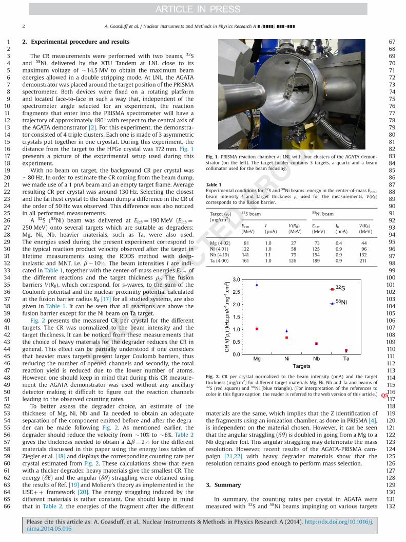
The CR measurements were performed with two beams, 32Sand 58Ni, delivered by the XTU Tandem at LNL close to itsmaximum voltage of �14.5 MV to obtain the maximum beamenergies allowed in a double stripping mode. At LNL, the AGATAdemonstrator was placed around the target position of the PRISMAspectrometer. Both devices were fixed on a rotating platformand located face-to-face in such a way that, independent of thespectrometer angle selected for an experiment, the reactionfragments that enter into the PRISMA spectrometer will have atrajectory of approximately 1801 with respect to the central axis ofthe AGATA demonstrator [2]. For this experiment, the demonstra-tor consisted of 4 triple clusters. Each one is made of 3 asymmetriccrystals put together in one cryostat. During this experiment, thedistance from the target to the HPGe crystal was 172 mm. Fig. 1presents a picture of the experimental setup used during thisexperiment.
With no beam on target, the background CR per crystal was�80 Hz. In order to estimate the CR coming from the beam dump,we made use of a 1 pnA beam and an empty target frame. Averageresulting CR per crystal was around 130 Hz. Selecting the closestand the farthest crystal to the beam dump a difference in the CR ofthe order of 50 Hz was observed. This difference was also noticedin all performed measurements.
A 32S (58Ni) beam was delivered at Elab ¼ 190 MeV (Elab ¼250 MeV) onto several targets which are suitable as degraders:Mg, Ni, Nb, heavier materials, such as Ta, were also used.The energies used during the present experiment correspond tothe typical reaction product velocity observed after the target inlifetime measurements using the RDDS method with deep-inelastic and MNT, i.e. β� 10%. The beam intensities I are indi-cated in Table 1, together with the center-of-mass energies Ec:m: ofthe different reactions and the target thickness ρt. The fusionbarriers VðRBÞ, which correspond, for s-waves, to the sum of theCoulomb potential and the nuclear proximity potential calculatedat the fusion barrier radius RB [17] for all studied systems, are alsogiven in Table 1. It can be seen that all reactions are above thefusion barrier except for the Ni beam on Ta target.
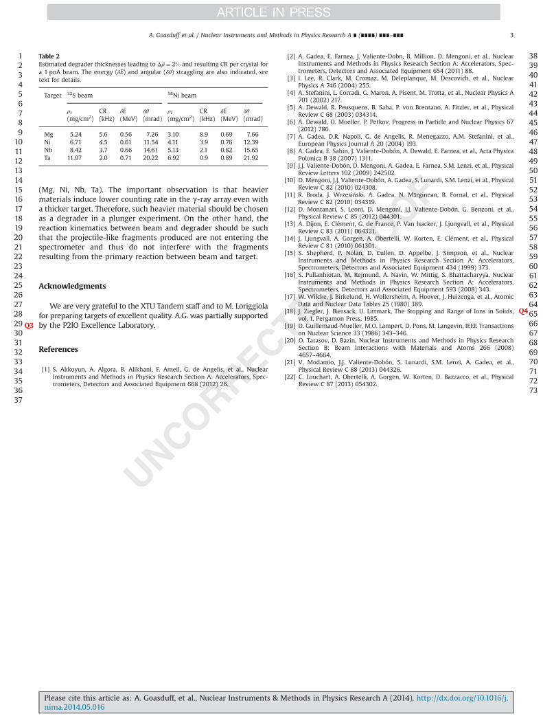
Fig. 2 presents the measured CR per crystal for the differenttargets. The CR was normalized to the beam intensity and thetarget thickness. It can be noticed from these measurements thatthe choice of heavy materials for the degrader reduces the CR ingeneral. This effect can be partially understood if one considersthat heavier mass targets present larger Coulomb barriers, thusreducing the number of opened channels and secondly, the totalreaction yield is reduced due to the lower number of atoms.However, one should keep in mind that during this CR measure-ment the AGATA demonstrator was used without any ancillarydetector making it difficult to figure out the reaction channelsleading to the observed counting rates.
To better assess the degrader choice, an estimate of thethickness of Mg, Ni, Nb and Ta needed to obtain an adequateseparation of the component emitted before and after the degra-der can be made following Fig. 2. As mentioned earlier, thedegrader should reduce the velocity from �10% to �8%. Table 2gives the thickness needed to obtain a Δβ¼ 2% for the differentmaterials discussed in this paper using the energy loss tables ofZiegler et al. [18] and displays the corresponding counting rate percrystal estimated from Fig. 2. These calculations show that evenwith a thicker degrader, heavy materials give the smallest CR. Theenergy (δE) and the angular (δθ) straggling were obtained usingthe results of Ref. [19] and Moliere's theory as implemented in theLISEþþ framework [20]. The energy straggling induced by thedifferent materials is rather constant. One should keep in mindthat in Table 2, the energies of the fragment after the different
materials are the same, which implies that the Z identification ofthe fragments using an ionization chamber, as done in PRISMA [4],is independent on the material chosen. However, it can be seenthat the angular straggling (δθ) is doubled in going from a Mg to aNb degrader foil. This angular straggling may deteriorate the massresolution. However, recent results of the AGATA-PRISMA cam-paign [21,22] with heavy degrader materials show that theresolution remains good enough to perform mass selection.
3. Summary
In summary, the counting rates per crystal in AGATA weremeasured with 32S and 58Ni beams impinging on various targets
123456789
101112131415161718192021222324252627282930313233343536373839404142434445464748495051525354555657585960616263646566
676869707172737475767778798081828384858687888990919293949596979899
100101102103104105106107108109110111112113114115116117118119120121122123124125126127128129130131132
Fig. 1. PRISMA reaction chamber at LNL with four clusters of the AGATA demon-strator (on the left). The target holder contains 3 targets, a quartz and a beamcollimator used for the beam focusing.
Table 1Experimental conditions for 32S and 58Ni beams: energy in the center-of-mass Ec:m: ,beam intensity I and target thickness ρt used for the measurements, VðRBÞcorresponds to the fusion barrier.
Target (ρt)(mg/cm2)
32S beam 58Ni beam
Ec:m:
(MeV)I(pnA)
VðRBÞ(MeV)
Ec:m:
(MeV)Ib(pnA)
VðRBÞ(MeV)
Mg (4.02) 81 1.0 27 73 0.4 44Ni (4.01) 122 1.0 58 125 0.9 96Nb (4.19) 141 1.1 79 154 0.9 132Ta (4.00) 161 1.0 126 189 0.9 211
TargetsMg Ni Nb Ta
CR
/(I*
ρ t) [k
Hz.
pnA
-1.m
g-1.c
m2 ]
0.0
0.5
1.0
1.5
2.0
2.5
3.0
S32
Ni58
Fig. 2. CR per crystal normalized to the beam intensity (pnA) and the targetthickness (mg/cm2) for different target materials Mg, Ni, Nb and Ta and beams of32S (red square) and 58Ni (blue triangle). (For interpretation of the references tocolor in this figure caption, the reader is referred to the web version of this article Q5.)
A. Goasduff et al. / Nuclear Instruments and Methods in Physics Research A ∎ (∎∎∎∎) ∎∎∎–∎∎∎2
Please cite this article as: A. Goasduff, et al., Nuclear Instruments & Methods in Physics Research A (2014), http://dx.doi.org/10.1016/j.nima.2014.05.016i
(Mg, Ni, Nb, Ta). The important observation is that heaviermaterials induce lower counting rate in the γ-ray array even witha thicker target. Therefore, such heavier material should be chosenas a degrader in a plunger experiment. On the other hand, thereaction kinematics between beam and degrader should be suchthat the projectile-like fragments produced are not entering thespectrometer and thus do not interfere with the fragmentsresulting from the primary reaction between beam and target.
Acknowledgments
We are very grateful to the XTU Tandem staff and to M. Loriggiolafor preparing targets of excellent quality. A.G. was partially supportedby the P2IO Excellence LaboratoryQ3 .
References
[1] S. Akkoyun, A. Algora, B. Alikhani, F. Ameil, G. de Angelis, et al., NuclearInstruments and Methods in Physics Research Section A: Accelerators, Spec-trometers, Detectors and Associated Equipment 668 (2012) 26.
[2] A. Gadea, E. Farnea, J. Valiente-Dobn, B. Million, D. Mengoni, et al., NuclearInstruments and Methods in Physics Research Section A: Accelerators, Spec-trometers, Detectors and Associated Equipment 654 (2011) 88.
[3] I. Lee, R. Clark, M. Cromaz, M. Deleplanque, M. Descovich, et al., NuclearPhysics A 746 (2004) 255.
[4] A. Stefanini, L. Corradi, G. Maron, A. Pisent, M. Trotta, et al., Nuclear Physics A701 (2002) 217.
[5] A. Dewald, R. Peusquens, B. Saha, P. von Brentano, A. Fitzler, et al., PhysicalReview C 68 (2003) 034314.
[6] A. Dewald, O. Moeller, P. Petkov, Progress in Particle and Nuclear Physics 67(2012) 786.
[7] A. Gadea, D.R. Napoli, G. de Angelis, R. Menegazzo, A.M. Stefanini, et al.,European Physics Journal A 20 (2004) 193.
[8] A. Gadea, E. Sahin, J. Valiente-Dobón, A. Dewald, E. Farnea, et al., Acta PhysicaPolonica B 38 (2007) 1311.
[9] J.J. Valiente-Dobón, D. Mengoni, A. Gadea, E. Farnea, S.M. Lenzi, et al., PhysicalReview Letters 102 (2009) 242502.
[10] D. Mengoni, J.J. Valiente-Dobón, A. Gadea, S. Lunardi, S.M. Lenzi, et al., PhysicalReview C 82 (2010) 024308.
[11] R. Broda, J. Wrzesiński, A. Gadea, N. Mărginean, B. Fornal, et al., PhysicalReview C 82 (2010) 034319.
[12] D. Montanari, S. Leoni, D. Mengoni, J.J. Valiente-Dobón, G. Benzoni, et al.,Physical Review C 85 (2012) 044301.
[13] A. Dijon, E. Clément, G. de France, P. Van Isacker, J. Ljungvall, et al., PhysicalReview C 83 (2011) 064321.
[14] J. Ljungvall, A. Gor̈gen, A. Obertelli, W. Korten, E. Clément, et al., PhysicalReview C 81 (2010) 061301.
[15] S. Shepherd, P. Nolan, D. Cullen, D. Appelbe, J. Simpson, et al., NuclearInstruments and Methods in Physics Research Section A: Accelerators,Spectrometers, Detectors and Associated Equipment 434 (1999) 373.
[16] S. Pullanhiotan, M. Rejmund, A. Navin, W. Mittig, S. Bhattacharyya, NuclearInstruments and Methods in Physics Research Section A: Accelerators,Spectrometers, Detectors and Associated Equipment 593 (2008) 343.
[17] W. Wilcke, J. Birkelund, H. Wollersheim, A. Hoover, J. Huizenga, et al., AtomicData and Nuclear Data Tables 25 (1980) 389.
[18] J. Ziegler, J. Biersack, U. Littmark, The Stopping and Range of Ions in Solids Q4,vol. 1, Pergamon Press, 1985.
[19] D. Guillemaud-Mueller, M.O. Lampert, D. Pons, M. Langevin, IEEE Transactionson Nuclear Science 33 (1986) 343–346.
[20] O. Tarasov, D. Bazin, Nuclear Instruments and Methods in Physics ResearchSection B: Beam Interactions with Materials and Atoms 266 (2008)4657–4664.
[21] V. Modamio, J.J. Valiente-Dobón, S. Lunardi, S.M. Lenzi, A. Gadea, et al.,Physical Review C 88 (2013) 044326.
[22] C. Louchart, A. Obertelli, A. Gor̈gen, W. Korten, D. Bazzacco, et al., PhysicalReview C 87 (2013) 054302.
123456789
10111213141516171819202122232425262728293031323334353637
383940414243444546474849505152535455565758596061626364656667686970717273
Table 2Estimated degrader thicknesses leading to Δβ¼ 2% and resulting CR per crystal fora 1 pnA beam. The energy (δE) and angular (δθ) straggling are also indicated, seetext for details.
Target 32S beam 58Ni beam
ρt(mg/cm2)
CR(kHz)
δE(MeV)
δθ
(mrad)ρt(mg/cm2)
CR(kHz)
δE(MeV)
δθ
(mrad)
Mg 5.24 5.6 0.56 7.26 3.10 8.9 0.69 7.66Ni 6.71 4.5 0.61 11.54 4.11 3.9 0.76 12.39Nb 8.42 3.7 0.66 14.61 5.13 2.1 0.82 15.65Ta 11.07 2.0 0.71 20.22 6.92 0.9 0.89 21.92
A. Goasduff et al. / Nuclear Instruments and Methods in Physics Research A ∎ (∎∎∎∎) ∎∎∎–∎∎∎ 3
Please cite this article as: A. Goasduff, et al., Nuclear Instruments & Methods in Physics Research A (2014), http://dx.doi.org/10.1016/j.nima.2014.05.016i