fike502998-recto-tsj.indd.4.ps, page 1-3 @ normalize
TRANSCRIPT

FIKE CORPORATION
UVOLNĚNÍ TLAKUPRŮVODCE VÝROBKY

O e R
py
pJ
• • • • • • •
• • • • • •
• • • • • • •
• • • • •
• • • • • • •
• • • • • • •
• • • • • • • •
• • • • • • • •
• • • • • • •
• • • • • •
• • • • • • •
• • • • • • •
• • • • •
• • • •
• • • •
OCHRANA PROTI NADMĚRNÉMU TLAKU
Již 60 let udává společnost Fike směr v inovacích průtržných membrán a metod uvolnění tlaku. Výrobky Fike odpovídají
všem světovým předpisům a normám a splňují nebo překračují požadavky průmyslu na výkon, spolehlivost a kvalitu.
Počínaje zabezpečením vašich náročných výrobních procesů a konče ochranou vašich pojistných ventilů jsou výrobky
Fike součástí kritické cesty ke snížení vašich nákladů a dosažení vyšších zisků.
Obvyklé příčiny nadměrného tlaku:
• zablokování výpusti
• teplotní dilatace
• neřízená chemická reakce
• vnější požár nebo únik chladiva
• únik výplachového plynu
Nezabezpečení procesu může způsobit::
• mechanické poškození
• únik produktu
• ekologické škody
• zranění osob
• prostoje ve výrobě
Typ průtržné membrányCharakteristické vlastnosti Technologická média Držáky průtržných membrán
Součinitel využití
Netříštivé Odolnéproti vakuu
Pulzující nebo cyklické
zatíženíSanitární Polymer Kapalina
Páraplyn
Typ spojený svorníky
Nastavení torzního momentu
Typ zátka/ šroub
Spojka Ochranné kroužky Protipříruby
Směr působení
tlakuModel
Fike Provedení Rozsah velikostí
Rozsah průtržného tlaku
Na
konv
exní
stra
něko
nkáv
ní st
raně
SRL
SRX
MRK
S3
SR-H
SHX
Poly-SD
SCRD
SCRD FSR
HO/HOV
LO-V
P Series
AD Series
GD Series
ERD
Obráceně vypuklé s drážkou,nízký průtržný tlak
Obráceně vypuklé s drážkou
Obráceně svypuklé nožovými břity
Obráceně vypuklé s drážkou, hladce klenuté,
sanitární
Obráceně vypuklé s drážkou, sanitární
Velký rozsah průtržného tlaku
Konvexně vypuklé s drážkou
Konvexně vypuklé s drážkou
Konvexně vypuklé s drážkou,
pro vysoký tlak
Kompozit
Kompozit
Konvexní klenuté
Ploché, kompozit
Grafi t
Pro protlačovací lisy
1 - 8 in25 - 200 mm
1 - 24 in25 - 600 mm
1 - 42 in 25 - 1100 mm
1-1/2 - 4 in40 - 100 mm
1-1/2 - 4 in40 - 100 mm
1 1/2 - 2 in40 - 50 mm
1/2 - 24 in15 - 600 mm
1/2 - 24 in15 - 600 mm
1 - 24 in25 - 600 mm
1 - 42 in
25 - 1100 mm
3 - 8 in80 - 200 mm
1/2 - 24 in15 - 600 mm
2 - 24 in50-600 mm
1/2 - 24 in15 - 600 mm
3/16 - 5 in4.5 - 127 mm
0,69 - 22,07 bar
0,70 - 22,49 kg/cm2
1,9 - 49,7 bar1,9 - 50,62 kg/cm2
0,3 - 99,3 bar0,28 - 101,24 kg/cm2
0,69 - 4,13 bar
0,70 - 4,21 kg/cm2
0,84 - 9,84 kg/cm2
21,1 - 105,6 bar20,7 - 103,4 kg/cm2
1,38 - 206,8 bar1,40 - 210,92 kg/cm2
10,35 - 413,7 bar10,55 - 421,84 kg/cm2
6,9 - 413,7 bar7,03 - 421,84 kg/cm2
10 - 413,7 bar11 - 421,84 kg/cm2
0,01 - 10 bar0,01 - 10 kg/cm2
10 - 6897 bar11 - 7030 kg/cm2
07 - 1,03 bar07 - 1,05 kg/cm2
02 - 68,9 bar02 - 70,31 kg/cm2
103,4 - 3448 bar105,46 - 3515 kg/cm2
95%
95%
95%
95%
95%
95%
95%
95%
95%
85%
85%
80%
55%
85%
95%

SRX
O e
p y
95%
SR-H
S3/SHX
SRL
SCRD-FSR
POLY-SD
AD
HOV/LO-V
95%
O e
J
O e
J
O e
p y
J
O e
J
p y
O e
p
J
O
J
O
J
e
p R
95%
95%
95%
95%
55%
85%
• Splňují požadavky SIP/CIP
• Pro potravinářství, výrobu nápojů, farmaceutický průmysl a biotechnologie
• S3 – hladký povrch bez vrubů
Vlastnosti Média
Držáky
Vlastnosti Média
Držáky
• Nejvyšší životnost
• DiscLocTM – ustavovací kolík pro správné nastavení polohy
• SRL – plně hydraulické ovládání
Vlastnosti Média
Držáky
Vlastnosti Média
Držáky
OBRÁCENĚ VYPUKLÉ S DRÁŽKOU
S A N I TÁ R N Í KONVEXNĚ VYPUKLÉ S DRÁŽKOU
• Konstrukce zabezpečená proti poruchám při každé orientaci
membrány
• Poly-SD – ideální pro polymerizační procesy
• SCRD-FSR – kroužek s drážkou brání posunutí
Vlastnosti Média
Držáky
Vlastnosti Média
Držáky
K O M P O Z I T
• Odolnost proti vakuu jako volitelné provedení
• Vícevrstvá konstrukce s mechanicky zeslabenou plochou
• AD – konstrukce pro atmosférické nádoby
Vlastnosti Média
Držáky
Vlastnosti Média
Držáky
PŘEHLED VÝROBKŮ

95%CPV
e
J
O e
J
p R
p
P
p R
p
75%
75%
O e
p
MRK 95%
GD
J
85%
O
ERD
J
95%
e
P SERIES
• Konvexní klenutá konstrukce
• Šikmé sedlo 30°
• Odolnost proti vakuu jako volitelné provedení
Vlastnosti Média
Držáky
Vlastnosti Média
Držáky
S P E C I Á L N Í A P L I K A C E
• ERD – ochrana pro procesy protlačování; dostupná v různých velikostech a s různým průtržným tlakem• MRK – obráceně vypuklá konstrukce s nožovými břity• GD – grafi tová konstrukce inertní vůči většině chemických
látek
Vlastnosti Média
Vlastnosti Média Držáky
Vlastnosti Média Držáky
Společnost Fike vyrábí držáky nejrůznější konstrukce a provedení tak, aby vyhovovaly vašim způsobům použití a technologickým procesům. Některé průtržné membrány vyžadují vlastní specifi cký typ držáku, jiné mohou být montovány do držáků různého typu.
K dispozici jsou tyto volitelné doplňky držáků (některé z nich nejsou u určitých držáků použitelné):
• Indikátor protržení
• Ventil omezující průtok
• Otočný šroub s okem
• Kontrolní kohout
• Stavěcí šrouby
• Hák tvaru J
• Šrouby a matice
• Další volitelné doplňky
• Nejobvyklejší dvoudílná
konstrukce pro upevnění mezi
dvěma přírubami
DRŽÁK GI
NASTAVENÍ TORZNÍHO MOMENTU• Konstrukce umožňující
smontování a nastaveni torního momentu před instalací
MOSAZNÉ DRŽÁKY NA JEDNO POUŽITÍ, SPOJKY,DRŽÁKY TYPU ZÁTKA/ŠROUB
DRŽÁK TVARU T PRO VISKÓZNÍ • Konstrukce umožňující
proudění viskózní kapaliny, zabraňující jejímu hromadění a ucpávání
TM
333
33
3
V
AL
VE
GU
AR
D
FIKE
Nechráněný ventil Ventil s ochranou
VALVEGUARD
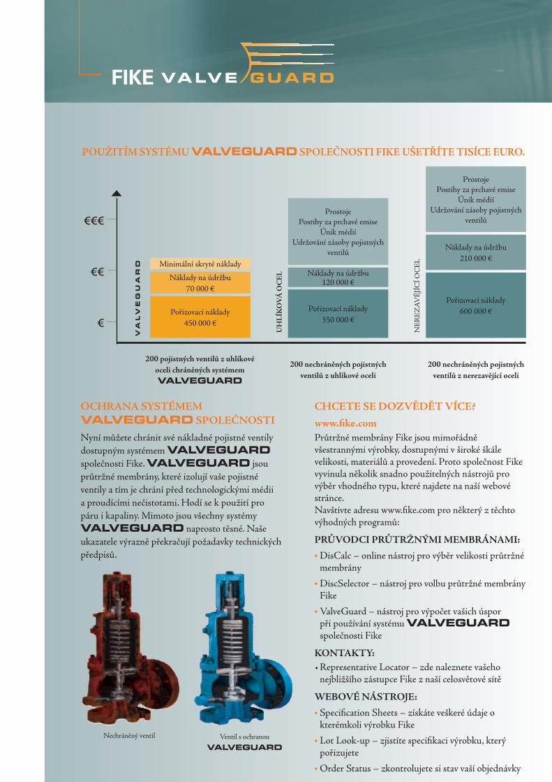
Nyní můžete chránit své nákladné pojistné ventily dostupným systémem VALVEGUARD společnosti Fike. VALVEGUARD jsou průtržné membrány, které izolují vaše pojistné ventily a tím je chrání před technologickými médii a proudícími nečistotami. Hodí se k použití pro páru i kapaliny. Mimoto jsou všechny systémy VALVEGUARD naprosto těsné. Naše ukazatele výrazně překračují požadavky technických předpisů.
OCHRANA SYSTÉMEM VALVEGUARD SPOLEČNOSTI
200 pojistných ventilů z uhlíkové oceli chráněných systémem VALVEGUARD
CHCETE SE DOZVĚDĚT VÍCE?
www.fi ke.com
200 nechráněných pojistných ventilů z uhlíkové oceli
200 nechráněných pojistných ventilů z nerezavějící oceli
Průtržné membrány Fike jsou mimořádně všestrannými výrobky, dostupnými v široké škále velikosti, materiálů a provedení. Proto společnost Fike vyvinula několik snadno použitelných nástrojů pro výběr vhodného typu, které najdete na naší webové stránce.Navštivte adresu www.fi ke.com pro některý z těchto výhodných programů:
PRŮVODCI PRŮTRŽNÝMI MEMBRÁNAMI:
• DisCalc – online nástroj pro výběr velikosti průtržné membrány
• DiscSelector – nástroj pro volbu průtržné membrány Fike
• ValveGuard – nástroj pro výpočet vašich úspor při používání systému VALVEGUARD společnosti Fike
KONTAKTY:• Representative Locator – zde naleznete vašeho
nejbližšího zástupce Fike z naší celosvětové sítě
WEBOVÉ NÁSTROJE:
• Specifi cation Sheets – získáte veškeré údaje o kterémkoli výrobku Fike
• Lot Look-up – zjistíte specifi kaci výrobku, který pořizujete
• Order Status – zkontrolujete si stav vaší objednávky
Pořizovací náklady450 000 €
Náklady na údržbu70 000 €
Minimální skryté náklady
ProstojePostihy za prchavé emise
Únik médiíUdržování zásoby pojistných
ventilů
Náklady na údržbu120 000 €
Pořizovací náklady350 000 €
ProstojePostihy za prchavé emise
Únik médiíUdržování zásoby pojistných
ventilů
Náklady na údržbu210 000 €
Pořizovací náklady600 000 €
NE
RE
ZA
VĚ
JÍC
Í OC
EL
UH
LÍK
OV
Á O
CE
L
POUŽITÍM SYSTÉMU VALVEGUARD SPOLEČNOSTI FIKE UŠETŘÍTE TISÍCE EURO.
KONTAKTUJTE FIKE
Společnost Fike® je celosvětovým týmem zkušených odborníků usilujících o bezpečnost životů i podnikání. Pracujeme v těsném kontaktu s našimi zákazníky
na řešení složitých problémů se snadno použitelnými výrobky a službami.
AMERIKA
FIKE CORPORATIONBlue Springs, MO 64015 USATel: +1-816-229-3405Email: [email protected]
FIKE CANADABurlington, ON L7L 5L6CanadaTel: +1-905-681-3100 Email: [email protected]
FIKE LATINA LTDAJundiarBrazilTel: +55-11-4525-1277Email: [email protected]
EVROPA
FIKE EUROPE2200 HerentalsBelgiumTel: +32-14-210031E-mail: [email protected]
FIKE UNITED KINGDOMMaidstone, Kent, ME 14 1PFUnited KingdomTel: +44-1-622-677081Email: [email protected]
FIKE FRANCEF-95526 Cergy Pontoise CedexFranceTel: +33-1-30-31-31-32Email: [email protected]
FIKE DEUTSCHLAND68309 MannheimGermanyTel: +49-621-321-67-0E-mail: [email protected]
FIKE ITALIAI-20129 MilanoItalyTel: +39-02-2952-4166Email: [email protected]
FIKE IBERICAE-08029 BarcelonaSpainTel: +34-93-6000-800Email: [email protected]
ASIE
FIKE ASIA PACIFIC SDN BHDSelangor Darul EhsanMalaysiaTel: +60-3-7859-1462Email: [email protected]
FIKE JAPANTokyo 105-0001JapanTel +81-335-951-291Email: [email protected]
FIKE INDIA PVT. LTD.Erandawana, Pune – 411004IndiaTel: +91-20-5453336Email: [email protected]
FIKE EUROPE2200 HerentalsBelgiumTel: +32-14-210031Fax: +32-14-210743E-mail: [email protected]
VALVEGUARD, DiscLoc, SRL, SRX, MRK, S3, SR-H, Poly-SD, SCRD, SCRD FSR, HO, HOV, P, CPV, AD, GD, ERD, DisCalc,
DiscSelector, DiscLoc, Lot Look-up, Fike a Fike Corporation jsou obchodní značky nebo registrované obchodní značky společnosti Fike Corporation.
© Copyright 2004, Fike Corporation. Všechna práva vyhrazena. Form No. 8.0000.00.6
www.fike.be
Zastoupení pro Českou a Slovenskou Republiku REGOM INSTRUMENTS s.r.o. Brabcova 2/1159 CZ-147 00 Praha 4 Česká Republika Tel: +420 241 402 206 Fax: +420 241 400 290 Email: [email protected]

BURSTING DISC SIZING
Introduction
Safety devices for the protection of pressure equipmentagainst excessive pressure include pressure relief devices suchas safety valves and bursting disc safety devices which,dependent upon the application, may be used either as thesole pressure relieving devices or in conjunction with eachother.When sizing of bursting disc safety devices in undertaken, it isimportant to consider not only the pressure relief devices butthe whole of the pressure relief system so as not to reduce therelieving capacity below that required or adversely affect theproper operation of the pressure relieving devices.The objective of this bulletin is to provide detailed guidancefor sizing bursting discs using standard methodologies found inEN/ISO 4126-6, ASME Section VIII Div. 1, API RP520, andCrane TP-410.This brochure is part of a series covering Bursting Disc Sizing.Specific folders, describing the sizing requirements in accordance with ASME and EN/ISO, and the use of bursting discsin combination with safety relief valves, are available. To assist in the sizing process, Fike offers disCalc, a PC-basedsizing program. Call Fike or your local representative for your complementary copy.
Overpressure Allowance
When sizing pressure relief devices, generally the Pressure Vessel Codes define the maximum pressure that may buildup in the pressure vessel while the device is relieving. This pressure varies depending on the applicable code orstandard and on the application of the device. The following table defines the various overpressure allowances astypically allowed for by the ASME Code:
Primary ReliefApplication
Multiple Devices(Secondary)
External Fire External Fire(Ambient temperature compressedgas storage vessels only)
10% above the vesselMAWP*
16% above the vesselMAWP*
21% above the vesselMAWP*
20% above the vessel MAWP*
*MAWP = Maximum Allowable Working Pressure, a term used to designate the pressure for which the recipient has been designed
Typical application of bursting disc safety device.

Within the scope of the various pressure vessel codes, the use of bursting disc devices is permitted to achieveprotection of such system.
A bursting disc safety device is a non-reclosing pressure relief device used to protect pressure equipment such aspressure vessels, piping, gas cylinders or other enclosures from excessive pressure and/or excessive vacuum.A bursting disc safety device typically comprises an assembly of components including a bursting disc, a burstingdisc holder and, where necessary, other components such as back-pressure supports, stiffening rings etc.
The bursting disc is pressure-containing and pressure-sensitive part of the bursting disc safety device and isdesigned to open by bursting at a pre-determined pressure. There are many different types of bursting disc safetydevices manufactured in corrosion resistant materials, both metallic and non-metallic, to cover a wide range ofnominal size, burst pressures and temperatures.
Bursting Disc Sizing Methodologies
All sizing equations for pressure relief devices are derived from the general Bernoulli equations for flow of liquids,steam and vapour. The pressure relief device is considered to behave similar to an orifice device introducing acertain amount of flow resistance. The sizing is specific to single phase flow conditions; in such cases where two-phase flow conditions can occur the given sizing methods are not to be used. Specialists should be consulted forsuch applications.
1. The ISO/EN Standards for the use of bursting disc devices offer two different methods; a simplifiedapproach, neglecting pressure drops in the inlet and discharge piping with limited range of application, and asecond, more comprehensive method where consideration is given to the changes in pressure throughoutthe entire pressure relief system. It is important to select the sizing method that is relevant to the particularapplication and is correctly applied by qualified and experienced persons. Separate sizing rules are beingdeveloped to describe sizing of bursting disc devices when used in combination with pressure relief valves.
2.The ASME Code recognises 3 basic methodologies for sizing bursting disc devices:
2.1 Coefficient of Discharge Method (KD) — The value of KD is the coefficient of discharge that isapplied to the theoretical flow rate to arrive at a rated flow rate for simple systems.
When to use this method? Use this method for simple systems where the following conditions aretrue (8 &5 Rule). This method takes into account the vessel entranceeffects, 8 pipe diameters of inlet piping, 5 pipe diameters of dischargepiping, and effects of discharging to atmosphere. See schematic below.
8 & 5 Rule
The bursting disc is installedwithin 8 pipe diameters ofthe vessel.
The discharge piping doesnot exceed 5 pipe diameters.
The bursting disc devicedischarges directly tothe atmosphere.The inlet and outlet piping
is at least the same nominalpipe size as the burstingdisc device.

2.2 Resistance to Flow Method (KR) – The value of KR represents the velocity-head loss due to the pressurerelief device. This head loss is included in the overall system loss calculations to determine the size of the reliefsystem.
When to use this method? Use this method when the 8&5 Rule does not apply. When the bursting disc device is installed in combination with a pressure
relief valve this method can be used to calculate the pressure drop betweenthe pressure vessel and the valve.Use this method also where turbulent flow conditions are expected.
Bursting disc devices can be characterized as to their respective resistance to fluid flow. The KR-value representsthe velocity head loss due to the bursting disc device installed in the flow path. This head loss is included in theoverall system loss calculations to determine the capacity of the relief system.
Typical KR –values for most common Fike bursting discs are tabled below:
DiscType
SRX SRL SR-H Poly-SD(X-Score)
SCRD FSR HO/HOV P, CP, CPC
KR 0.99 0.38 1.88 0.99 0.55 2.02 1.35
DiscType
PV, CPV, CP-C,CPV-C
MRK P FSR GD GDI GDL GDV Bar Type
KR 3.50 1.56 0.55 0.26 0.64 0.64 3.4Consult Fike for KR-values for bursting disc types not listed.
International and national standards such as EN/ISO 4126-6 & ASME PTC25 provide standardized test methodsto measure the KR of the bursting disc devices. By the quantification of this performance characteristic, burstingdisc devices may be accounted for in the piping system sizing calculations in the same way as piping andpiping components (such as exit nozzles, elbows, tees, reducers, valves, etc.). Crane Co. Technical Paper N°410M list generally accepted flow resistance values for typical piping components such as elbows, reducers,etc.).
Note: it is important to understand that the certified KR is representative of the device (disc and holder), notsimply the bursting disc. In cases where there is no holder, the KR-value is for the disc, which is then defined asthe device.
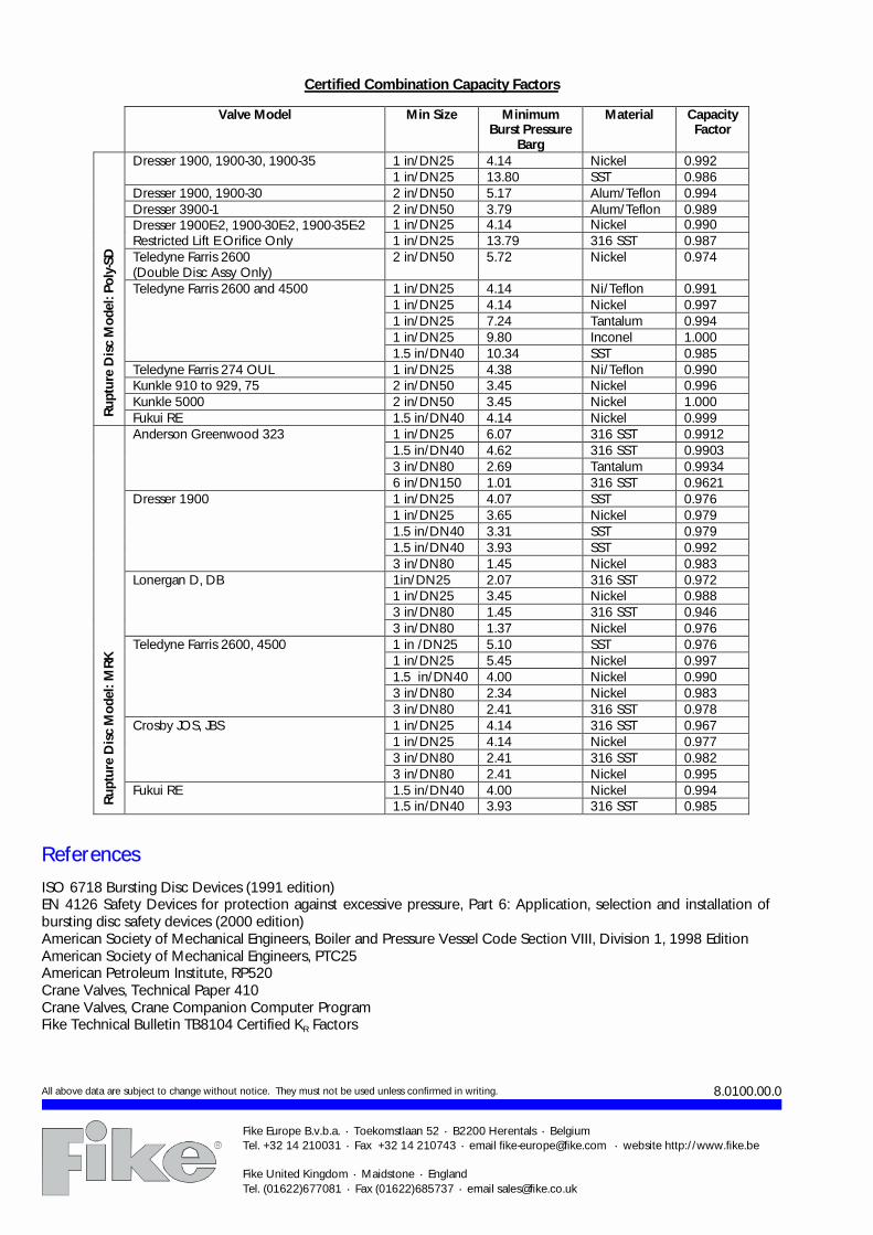
2.3 Combination Capacity Method – When a bursting disc device is installed in combinationwith a pressure relief valve (PRV), the valve capacity is derated by a default value of 0.9 or a testedvalue for the specific disc/valve combination. For specific application requirements when usingbursting disc devices in combination with PRV’s, consult Fike.The table on next page provides certified combination capacity factors that are published in theNational Board of Pressure Vessel Inspectors “Red Book”. To use these values, find the listing for thespecific rupture disc and valve models. Multiply the rated valve capacity by the combination capacityfactor to arrive at the capacity of the combination. Use the value of 0.90 for combinations in smallersizes or lower pressures than listed.
Fike Europe B.v.b.a. · Toekomstlaan 52 · B2200 Herentals · BelgiumTel. +32 14 210031 · Fax +32 14 210743 · email [email protected] · website http://www.fike.be
Fike United Kingdom · Maidstone · EnglandTel. (01622)677081 · Fax (01622)685737 · email [email protected]
8.0100.00.0
Certified Combination Capacity Factors
Valve Model Min Size MinimumBurst Pressure
Barg
Material CapacityFactor
1 in/DN25 4.14 Nickel 0.992Dresser 1900, 1900-30, 1900-351 in/DN25 13.80 SST 0.986
Dresser 1900, 1900-30 2 in/DN50 5.17 Alum/Teflon 0.994Dresser 3900-1 2 in/DN50 3.79 Alum/Teflon 0.989
1 in/DN25 4.14 Nickel 0.990Dresser 1900E-2, 1900-30E-2, 1900-35E-2Restricted Lift E Orifice Only 1 in/DN25 13.79 316 SST 0.987Teledyne Farris 2600(Double Disc Assy Only)
2 in/DN50 5.72 Nickel 0.974
1 in/DN25 4.14 Ni/Teflon 0.9911 in/DN25 4.14 Nickel 0.9971 in/DN25 7.24 Tantalum 0.9941 in/DN25 9.80 Inconel 1.000
Teledyne Farris 2600 and 4500
1.5 in/DN40 10.34 SST 0.985Teledyne Farris 274 OUL 1 in/DN25 4.38 Ni/Teflon 0.990Kunkle 910 to 929, 75 2 in/DN50 3.45 Nickel 0.996Kunkle 5000 2 in/DN50 3.45 Nickel 1.000
Ru
ptu
re D
isc
Mo
del:
Poly
-SD
Fukui RE 1.5 in/DN40 4.14 Nickel 0.9991 in/DN25 6.07 316 SST 0.99121.5 in/DN40 4.62 316 SST 0.99033 in/DN80 2.69 Tantalum 0.9934
Anderson Greenwood 323
6 in/DN150 1.01 316 SST 0.96211 in/DN25 4.07 SST 0.9761 in/DN25 3.65 Nickel 0.9791.5 in/DN40 3.31 SST 0.9791.5 in/DN40 3.93 SST 0.992
Dresser 1900
3 in/DN80 1.45 Nickel 0.9831in/DN25 2.07 316 SST 0.9721 in/DN25 3.45 Nickel 0.9883 in/DN80 1.45 316 SST 0.946
Lonergan D, DB
3 in/DN80 1.37 Nickel 0.9761 in /DN25 5.10 SST 0.9761 in/DN25 5.45 Nickel 0.9971.5 in/DN40 4.00 Nickel 0.9903 in/DN80 2.34 Nickel 0.983
Teledyne Farris 2600, 4500
3 in/DN80 2.41 316 SST 0.9781 in/DN25 4.14 316 SST 0.9671 in/DN25 4.14 Nickel 0.9773 in/DN80 2.41 316 SST 0.982
Crosby JOS, JBS
3 in/DN80 2.41 Nickel 0.9951.5 in/DN40 4.00 Nickel 0.994
Ru
ptu
re D
isc
Mo
del:
MR
K
Fukui RE1.5 in/DN40 3.93 316 SST 0.985
ReferencesISO 6718 Bursting Disc Devices (1991 edition)EN 4126 Safety Devices for protection against excessive pressure, Part 6: Application, selection and installation ofbursting disc safety devices (2000 edition)American Society of Mechanical Engineers, Boiler and Pressure Vessel Code Section VIII, Division 1, 1998 EditionAmerican Society of Mechanical Engineers, PTC25American Petroleum Institute, RP520Crane Valves, Technical Paper 410Crane Valves, Crane Companion Computer ProgramFike Technical Bulletin TB8104 Certified KR Factors
All above data are subject to change without notice. They must not be used unless confirmed in writing.

BURSTING DISCS
Conventional Prebulged Solid MetalType P
Technical Data
1. Consult Fike for discs > 24” (DN600).2. Maximum temperature for various coatings: Urethane Acrylic 65°C, Urethane 120°C, Tefl on 230°C.3. When burst pressure is over 70barg, these duties are recommended.4. Discs over DN600 (24”) have fl at seat design.
Fike Europe B.v.b.a. • Toekomstlaan 52 • B2200 Herentals • BelgiumTel. +32 14 210031 • Fax +32 14 210743 • email fi ke-europe@fi ke.com • website http://www.fi ke.be
Fike United Kingdom • Maidstone • EnglandTel. (01622)677081 • Fax (01622)685737 • email sales@fi ke.co.uk • website http://www.fi ke.co.uk
Type of Disc P(V), CP(V) - CPC, CP(V)-C
Action Forward-Acting
Sizes (1) 1/2”-44” DN15-DN1100
Disc Material Aluminium SST 316 Nickel 200 Monel 400 Inconel 600 Silver
Max. Operating Temperature °C 120 315 400 425 540 120
Protective Coating (2) Yes
Ratio of Operating Pressure to Minimum Burst Pressure
75% R R R R R R
Cycling Duty (3) NR NR NR NR NR NR
Pulsating Duty (light) (3) MC R R R R MC
Pulsating Duty (heavy) NR MC MC MC MC NR
Vacuum Service (without Vac Supp V) (3) NR NR NR NR NR NR
Vacuum Service (with Vac Supp V) (3) R R R R R R
Polymerisation Processes NR NR NR NR NR NR
Hydraulic Service R R R R R R
Minimal Fragmentation NR NR NR NR NR NR
Seat Confi guration (4) 30°
Use in Flanged Holders Type BT Yes
Use in Union Type Holders Type UT Yes
Use in Screw Type Holders Type ST Yes
R = RECOMMENDED MC = MARGINAL CONDITIONS NR = NOT RECOMMENDED
Features / Benefi ts
Simple , modular construction with large variety of ap-plication specifi c solutions 75% Operating Ratio Available in a wide range of corrosion resistant materi-als, optionally with protective coatings/lining Best cost-effective protection available Wide range of standard confi gurations to suit most industry applications
DescriptionThe design principle, used to ensure a predictable bursting pressure of these pressure safety devices, is simply a tension failure of a metal membrane. As the applied pressure approaches the bursting pressure, a point is reached where thinning of the metal occurs, leading rapidly to disc bursting and pressure relief.The conventional prebulged bursting discs are available in several confi gu-rations of different components.
P
Gi-BT

Burst pressures in barg at 22°C (1)
All above data are subject to change without notice. They must not be used unless confi rmed in writing. 8.1000.00.5
Fike Europe B.v.b.a. • Toekomstlaan 52 • B2200 Herentals • BelgiumTel. +32 14 210031 • Fax +32 14 210743 • email fi ke-europe@fi ke.com • website http://www.fi ke.be
Fike United Kingdom • Maidstone • EnglandTel. (01622)677081 • Fax (01622)685737 • email sales@fi ke.co.uk • website http://www.fi ke.co.uk
Disc Material Max.Temp.
°C
Bursting Disc Size
ANSI 1/2” 3/4” 1” 1½” 2” 3” 4” 6” 8” 10” 12” 14” 16” 18” 20” 24”
DN 15 20 25 40 50 80 100 150 200 250 300 350 400 450 500 600
Aluminium 120 Min 4.5 3.1 2.1 1.6 1.0 0.7 0.6 0.5 0.34 0.31 0.22 0.19 0.17 0.16 0.14 0.1
Max 79.3 46.9 35.9 23.4 15.2 10.7 7.9 5.9 4.5 3.4 3.1 2.8 2.4 2.1 1.7 1.4
AluminiumTefl on coated one side
120 Min 6.2 4.1 3.4 2.4 1.9 1.7 1.0 0.7 0.6 0.6 0.5 0.4 0.4 0.4 0.4 0.4
Max 79.3 46.9 35.9 23.4 15.2 10.7 7.9 5.9 4.5 3.4 3.1 2.8 2.4 2.1 1.7 1.4
AluminiumTefl on coated two sides
120 Min 9.0 6.2 5.2 3.4 2.8 2.1 1.4 1.0 0.7 0.7 0.6 0.6 0.6 0.6 0.6 0.6
Max 79.3 46.9 35.9 23.4 15.2 10.7 7.9 5.9 4.5 3.4 3.1 2.8 2.4 2.1 1.7 1.4
Silver 120 Min 16.9 12.1 8.6 5.9 3.8 2.4 1.7 1.4 1.2 - - - - - - -
Max 207 207 207 207 172 138 103 69 34 - - - - - - -
AISI 316 Stainless Steel
315 Min 34.5 27.6 17.2 13.1 7.6 6.2 4.1 3.5 2.8 2.1 1.9 1.7 1.5 1.2 1 1.7
Max 690 690 414 207 207 207 207 149 99 50 50 50 50 50 50 50
Nickel 200 400 Min 19 12.1 8.3 6.2 4.1 2.8 2.1 1.7 1.2 1.2 1.2 1 0.8 0.8 0.8 1.5
Max 207 207 207 207 207 207 207 149 99 50 50 50 50 50 50 50
Monel 400 425 Min 26.2 20.7 11.7 7.9 4.5 3.5 2.6 2 1.6 1.6 1.3 1.2 1 1 1 3
Max 690 690 414 207 207 207 207 149 99 50 50 50 50 50 50 50
Inconel 600 540 Min 31 17.2 14.8 9.7 6.9 5.9 3.8 3.1 2.2 1.8 1.7 1.4 1.2 1.2 1 3.1
Max 690 690 414 207 207 207 207 149 99 50 50 50 50 50 50 50
Burst Pressure in bargat 22°C
Performance Toleranceat 22°C
≤ 1.5 ± 0.15 barg
1.5 < burst pr. < 2.76 stand. ± 10% / red. ± 0.15 barg
≥ 2.76 stand. ± 10% / red. ± 5%
Performance tolerance as specifi ed by ISO/EN is a total tolerance which includes both manufacturing and bursting tolerance.As per ISO/EN the bursting discs can be marked with:Specifi ed burst pressure with a performance tolerance (in % or a value).E.g.: 10barg at 22°C ±10% (±1barg).Maximum and minimum burst pressure.E.g.: Max 11barg at 22°C - min 9barg at 22°COn request bursting discs can be marked as per ASME code section VIII with the average burst test result and the bursting tolerance of ±5% for burst pressures ≥ 2.76barg, (0.15barg for burst pressures <2.76barg).(*) Consult Fike for possibility to reduce tolerances.
Performance Tolerances (*)
Notes1. Lower burst pressures may be possible – consult factory.

BURSTING DISCS
Conventional Prebulged CompositeType HO/HOV
Technical data
Notes1. Consult factory for discs larger than DN600 (24”).2. Maximum temperature for various coatings: Urethane Acrylic 65°C, Urethane 120°C, Tefl on 230°C3. Cycling duty and vacuum service only recommended with vacuum support - model HOV, model PLHOV.
Fike Europe B.v.b.a. • Toekomstlaan 52 • B2200 Herentals • BelgiumTel. +32 14 210031 • Fax +32 14 210743 • email fi ke-europe@fi ke.com • website http://www.fi ke.be
Fike United Kingdom • Maidstone • EnglandTel. (01622)677081 • Fax (01622)685737 • email sales@fi ke.co.uk • website http://www.fi ke.co.uk
R = RECOMMENDED MC = MARGINAL CONDITIONS NR = NOT RECOMMENDED
Type of Disc HO, HOV - PLHO, PLHOV (Tefl on seal only)
Action Forward-Acting
Sizes (1) 1/2”-44” DN15-DN1100
Disc Material Aluminium Sst 316 Nickel 200 Monel 400 Inconel 600 Silver
Max. Operating Temperature °C 120 315 400 425 540 120
Protective Coating (2) Yes
Ratio of Operating Pressure to Minimum Burst Pressure
85% (3) R R R R R R
Cycling Duty (3) R R R R R R
Pulsating Duty (light) R R R R R R
Pulsating Duty (heavy) R MC R R R MC
Full or Partial Vacuum (3) R R R R R R
Polymerisation Processes NR NR NR NR NR NR
Hydraulic Service R R R R R R
Minimal Fragmentation MC MC MC MC MC MC
Seat Confi guration 30°
Use in Flanged Holders Type BT Yes
Use in Union Type Holders Type UT Yes
Use in Screw Type Holders Type ST Yes
Features / Benefi ts
Simple, modular construction with large variety of ap-plication specifi c solutions 85% Operating Ratio Available in a wide range of corrosion resistant materi-als, including Tefl on Best cost-effective pressure protection available Wide range of standard confi gurations to suit most industry applications
The HO/HOV series bursting discs are consisting of 2 to 4 component parts that form a single unit. The basic components of the HO type are a seal member and a slotted top section. To ensure the predictable burst-ing pressure a tension failure of the mechanically weakened top section is programmed for, where the seal merely transmits the pressure load to the top section. Due to the modular design concept the HO/HOV type bursting discs are available in a large variety of executions to cover most industry requirements.

Burst pressures in barg at 22°C (1)
All above data are subject to change without notice. They must not be used unless confi rmed in writing. 8.1100.00.4
Fike Europe B.v.b.a. • Toekomstlaan 52 • B2200 Herentals • BelgiumTel. +32 14 210031 • Fax +32 14 210743 • email fi ke-europe@fi ke.com • website http://www.fi ke.be
Fike United Kingdom • Maidstone • EnglandTel. (01622)677081 • Fax (01622)685737 • email sales@fi ke.co.uk • website http://www.fi ke.co.uk
Seal Material Max.Temp.
°C
Bursting Disc Size
ANSI 1” 1½” 2” 3” 4” 6” 8” 10” 12” 14” 16” 18” 20” 24”
DN 25 40 50 80 100 150 200 250 300 350 400 450 500 600
Tefl on 260 Min 2.1 1.6 1.0 0.8 0.6 0.4 0.31 0.25 0.21 0.18 0.16 0.14 0.12 0.1
Max 32.0 21.0 13.7 9.65 7.24 5.51 4.82 4.48 3.79 3.44 3.10 2.75 2.41 2.75
Silver 120 Min 13 8.8 5.7 3.7 2.6 2.1 1.8 - - - - - - -
Max 414 207 207 207 155 103 52 - - - - - - -
Aluminium Tefl on coat one side
230 Min 5.2 3.7 2.9 2.6 1.6 1.0 0.8 0.8 0.8 0.6 0.6 0.6 0.6 0.6
Max 103 103 78 52 41 31 23 18 15 15 15 13 13 10
Aluminium 315 Min 3.5 2.4 1.6 1.0 0.8 0.8 0.6 0.4 0.3 0.3 0.3 0.3 0.3 0.3
Max 103 103 78 52 41 31 23 18 15 15 15 13 13 10
AISI 316Stainless Steel
315 Min 33.5 25.2 13.4 9.3 7.2 5.9 4.5 3.4 3.4 3.3 3.0 2.6 2.1 1.9
Max 414 207 207 207 207 149 99 50 50 50 50 50 50 50
Nickel 399 Min 13.1 8.6 5.2 3.2 2.6 2.3 1.7 1.4 1.4 1.4 1.2 1.2 1.2 2.8
Max 414 207 207 207 207 149 99 50 50 50 50 50 50 50
Monel 427 Min 17.2 12.1 7.2 5.5 3.7 3.0 2.6 2.1 1.9 1.8 1.7 1.5 1.4 3.8
Max 414 207 207 207 207 149 99 50 50 50 50 50 50 50
Inconel 538 Min 28.3 20.0 12.4 9.0 6.9 5.2 2.8 2.2 1.9 1.6 1.4 1.2 1.1 3.1
Max 414 207 207 207 207 149 99 50 50 50 50 50 50 50
Burst Pressure in bargat 22°C
Performance Toleranceat 22°C
≤ 1.5 ± 0.15 barg
1.5 < burst pr. < 2.76 stand. ± 10% / red. ± 0.15 barg
≥ 2.76 stand. ± 10% / red. ± 5%
Performance tolerance as specifi ed by ISO/EN is a total tolerance which includes both manufacturing and bursting tolerance.As per ISO/EN the bursting discs can be marked with:Specifi ed burst pressure with a performance tolerance (in % or a value).E.g.: 10barg at 22°C ±10% (±1barg).Maximum and minimum burst pressure.E.g.: Max 11barg at 22°C - min 9barg at 22°COn request bursting discs can be marked as per ASME code section VIII with the average burst test result and the bursting tolerance of ±5% for burst pressures ≥ 2.76barg, (0.15barg for burst pressures <2.76barg).(*) Consult Fike for possibility to reduce tolerances.
Tolerances (*)
Notes1. Lower burst pressures may be possible – consult factory.

!
"#$%#&'($&#
)
"#$%#&'($&#
)*
(( *!
() *
(+ *,
(" *,!
(- *,
(! *,,
(. *!!
(. *!!
(/ *!
(# *!,
.
($&#
"#$%#&'
0
!1"$02 34
! 1
! "#$%#&'($&#
"$3 5647
,8
&
9/
( ! :
(#&# 6
(;
<
!0
!5
!

! -) = 25=)55 / =)>50650 0=!<>50650 ?6= @ =**%% ! ABC9C- 03553?? D0C!< 03553D2??C @ C,%%
D50 5(;
$*( E
($&# "#$ .
#$+/ ($&# )'7& "$ F$ )'7&
G &14 74 G &1 7 "/
(>5 ) +
(<,
0%5 02 6 0%5 6 02 3 6 90 H2 66 60 05? 05? 620%5 %3 6 0%5 6?2 02 0 6 6 905 00 20 60 05? 05? 3
02 360 6 905 05 30 60 05? 05? H E%6 02 6 0%5 652 E5 3 6 90 0 2 26 6 0H0 0H0 ?
5 0 6 6 90 002 30 6 0H0 0H0 H %6 %3 6 2%D 252 36 6 0H0 0H0 0 0 02 6 0%5 652 52 3 6 90 0 2 3 6 526 526 H 0 %3 6 2%D 252 52 0 6 6 905 002 ? 6 526 526 00
52 360 6 903 02 D0 6 526 526 03 00%5 02 6 0%5 62 D5 6 D0 D0 06
6 3 6 905 0 2 D3 6 D0 D0 03
00%5 %3 6 %6 3 6 0 6 6 903 05 H5 6 D0 D0 0D26 360 6 95 062 0 0 6 D0 D0 5
E5 02 6 2%D 2 0 0 6 256 32 0D E5 77 D 2%D 3 0 3 6 256 32 50 E5 3 /7 D 2%D 3 E2 0 6 6 903 052 0 3 6 256 32 50
2 36 6 95 062 000 6 256 32 56 2 0 6 956 022 00? 6 256 32 5?
02 0 2%D 252 ED 3 6 903 002 05 6 ??D H 2 5? ED 0 6 D 903 05 060 6 ??D H 2 6
%3 D %6 352 D 36 D 95 062 063 6 ??D H 2 D D 0 D 956 03 025 6 ??D H 2 65 E0 0 03 D 903 052 035 6 0 56 002H D E0 526 D 95 06 033 6 0 56 002H 60
6 02 D 2%D 252 0?0 6 0 56 002H 63 E0 36 D 956 022 0?6 6 0 56 002H 6H
6 D %6 352 0?? 6 0 56 002H 20 E0 0 D 95? 03 0?D 6 0 56 002H 252
6 3 D ?%D ?2 0H 6 0 56 002H 36 3 02 D %6 352 02 0 03 D 95 02 50? 23 026 026D D0
E02 526 D 956 03 556 23 026 026D H0 3 05 %6 ? 02 36 D 9 0H2 56? 23 026 026D 05H
02 0 05 9 50 523 23 026 026D 066 3 3 05 0 H 53 23 026 026D 02?
5 0 03 D%05 95 02 5? 23 5 5 5 5 002 D 02 D %6 32 5?3 23 5 5 5 5 05
5 52 05 956 0? 5D5 23 5 5 5 5 05 5 6 05 95? 0D2 5DH 23 5 5 5 5 063
D 05 ?%D 3?2 2 23 5 5 5 5 0?D 5 36 05 9 50 D 3 5 5 5 5 0HD
D 3 05 00%D 0 0? 3 5 5 5 5 50H 5 0 05 9 5 56 3 5 5 5 5 52 E52 3 05 903 062 0? 3 526 5302 053 E52 0 05 95 032 5D 3 526 5302 025 E52 03 05 956 032 5D 3 526 5302 025
0 02 05 ?%D 3?2 3 3 526 5302 0?5 E52 52 05 95? 0D2 6 3 526 5302 0D5 E52 6 05 9 5 20 3 526 5302 50
0 03 0 D2 2D 3 526 5302 55D E 3 05 95 02 ? 3 6D 6D 0?0 E 0 05 95 062 ?3 3 6D 6D 0?H E 03 05 956 0? D6 3 6D 6D 5 5 52 03 95? 0H2 6 3 6D 6D 5??
05 02 05 ?%D ?2 6 3 3 6D 6D 533 05 03 00%D H2 6 03 9 502 60? 3? 6D 6D 6

BURSTING DISC HOLDERS
Union Type
DescriptionThe Fike union type bursting discs holders are easily adaptable to pressure system piping. They are used in applications where space is limited and where quick or frequent replacement of bursting discs may be neces-sary.
The union type bursting disc holder is a three-piece unit, consisting of a base fl ange (inlet), a holddown fl ange (outlet), and a union nut.
Union type holders are confi ned to ½”, ¾”, 1”, 1 ½” and 2” nominal pipe sizes.
Fike Europe B.v.b.a. • Toekomstlaan 52 • B2200 Herentals • BelgiumTel. +32 14 210031 • Fax +32 14 210743 • email fi ke-europe@fi ke.com • website http://www.fi ke.be
Fike United Kingdom • Maidstone • EnglandTel. (01622)677081 • Fax (01622)685737 • email sales@fi ke.co.uk • website http://www.fi ke.co.uk
Features / Benefi ts
Are more compact and easier to maintain than conventional fl ange type holders of comparable size. Can be ordered with welding or threaded connections or any combination of the two. Free venting outlets are also avail-able. Accept conventional prebulged solid metal disc and the conventional preb-ulged composite bursting disc series. Standard materials of construction, carbon steel and stainless steel AISI 316, other material combinations are available on request.
ASSEMBLY AUTHREADED BASE
FLAT HOLDDOWN
ASSEMBLY BUTHREADED BASE
THREADED HOLDDOWN
ASSEMBLY CUTHREADED BASE
WELDING HOLDDOWN
ASSEMBLY DUWELDING BASE
FLAT HOLDDOWN
ASSEMBLY EUWELDING BASE
THREADED HOLDDOWN
ASSEMBLY FUWELDING BASE
WELDING HOLDDOWN

All above data are subject to change without notice. They must not be used unless confi rmed in writing. 8.2200.00.2
Fike Europe B.v.b.a. • Toekomstlaan 52 • B2200 Herentals • BelgiumTel. +32 14 210031 • Fax +32 14 210743 • email fi ke-europe@fi ke.com • website http://www.fi ke.be
Fike United Kingdom • Maidstone • EnglandTel. (01622)677081 • Fax (01622)685737 • email sales@fi ke.co.uk • website http://www.fi ke.co.uk
Dimensions
Nominal Size Maximum Pressure Width across Flats mm
Approximate Height in mm
Inch mm Lbs barg AU BU CU DU EU FU
½”½”
DN15DN15
30006000
206413
4464
4154
6067
5767
4354
6067
5767
¾”¾”
DN20DN20
30006000
206413
6470
4848
7070
6464
5151
7373
6767
1”1”
DN25DN25
30006000
206413
7076
5459
7979
7878
5464
7986
7884
1 ½” DN40 3000 206 89 59 83 79 64 89 86
2” DN50 750 51 127 68 87 87 73 92 92
Connection Specifi cationsUnion type holders with threaded connections, such as assembly AU, BU, CU and EU are supplied with a female NPT thread as a standard. Other thread specifi cations, such as ISO, BSP, etc. are available on request.
Welded ConnectionsStandard union type holders with welded connections, such as assembly CU, BU, DU, EU and FU, are supplied with schedule 80 bevelled weld ends as a standard. Other specifi cations are available on request.
Table 1
BURSTING DISC HOLDERS
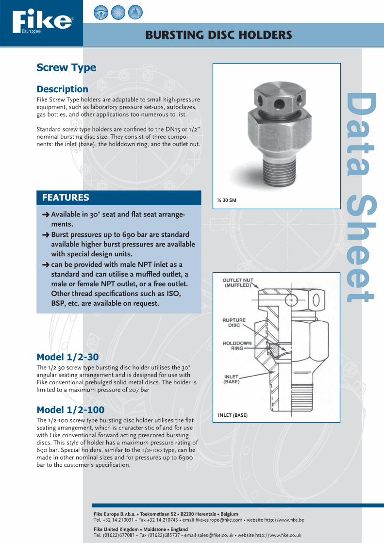
Screw Type
DescriptionFike Screw Type holders are adaptable to small high-pressure equipment, such as laboratory pressure set-ups, autoclaves, gas bottles, and other applications too numerous to list.
Standard screw type holders are confi ned to the DN15 or 1/2” nominal bursting disc size. They consist of three compo-nents: the inlet (base), the holddown ring, and the outlet nut.
Fike Europe B.v.b.a. • Toekomstlaan 52 • B2200 Herentals • BelgiumTel. +32 14 210031 • Fax +32 14 210743 • email fi ke-europe@fi ke.com • website http://www.fi ke.be
Fike United Kingdom • Maidstone • EnglandTel. (01622)677081 • Fax (01622)685737 • email sales@fi ke.co.uk • website http://www.fi ke.co.uk
FEATURES
Available in 30° seat and fl at seat arrange-ments. Burst pressures up to 690 bar are standard available higher burst pressures are available with special design units. can be provided with male NPT inlet as a standard and can utilise a muffl ed outlet, a male or female NPT outlet, or a free outlet. Other thread specifi cations such as ISO, BSP, etc. are available on request.
Model 1/2-30The 1/2-30 screw type bursting disc holder utilises the 30° angular seating arrangement and is designed for use with Fike conventional prebulged solid metal discs. The holder is limited to a maximum pressure of 207 bar
Model 1/2-100The 1/2-100 screw type bursting disc holder utilises the fl at seating arrangement, which is characteristic of and for use with Fike conventional forward acting prescored bursting discs. This style of holder has a maximum pressure rating of 690 bar. Special holders, similar to the 1/2-100 type, can be made in other nominal sizes and for pressures up to 6900 bar to the customer’s specifi cation.
½ 30 SM
INLET (BASE)

All above data are subject to change without notice. They must not be used unless confi rmed in writing. 8.2300.00.1
Fike Europe B.v.b.a. • Toekomstlaan 52 • B2200 Herentals • BelgiumTel. +32 14 210031 • Fax +32 14 210743 • email fi ke-europe@fi ke.com • website http://www.fi ke.be
Fike United Kingdom • Maidstone • EnglandTel. (01622)677081 • Fax (01622)685737 • email sales@fi ke.co.uk • website http://www.fi ke.co.uk
Dimensions
Model Connections Hex-Size mm Height mm
Inlet Outlet A B
1/2-30-SA 1/4”NPT Free 29 32 59
1/2-30-SA 1/2”NPT Free 29 32 59
1/2-30-SB 1/4”NPT ¼”NPT 29 32 79
1/2-30-SB 1/2”NPT 1/2”NPT 29 32 79
1/2-30-SM 1/4”NPT Muffl ed 29 32 64
1/2-30-SM 1/2”NPT Muffl ed 29 32 64
Table 1
Model Connections Hex Size mm Heightmm
Inlet Outlet A B
1/2-100-SA 1/4”NPT Free 29 32 54
1/2-100-SA 1/2”NPT Free 29 32 54
1/2-100-SB 1/4”NPT 1/4”NPT 29 32 75
1/2-100-SB 1/2”NPT 1/2”NPT 29 32 75
1/2-100-SM 1/4”NPT Muffl ed 29 32 59
1/2-100-SM 1/2”NPT Muffl ed 29 32 59
Table 2
BURSTING DISCS
Forward-Acting ScoredType POLY-SD, SCRD and SCRD-V
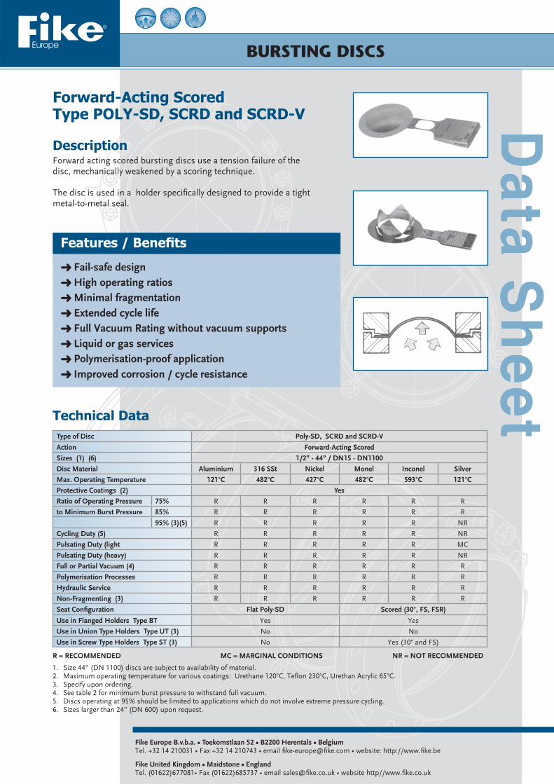
DescriptionForward acting scored bursting discs use a tension failure of the disc, mechanically weakened by a scoring technique.
The disc is used in a holder specifi cally designed to provide a tight metal-to-metal seal.
Technical Data
1. Size 44” (DN 1100) discs are subject to availability of material.2. Maximum operating temperature for various coatings: Urethane 120°C, Tefl on 230°C, Urethan Acrylic 65°C.3. Specify upon ordering.4. See table 2 for minimum burst pressure to withstand full vacuum.5. Discs operating at 95% should be limited to applications which do not involve extreme pressure cycling.6. Sizes larger than 24” (DN 600) upon request.
Fike Europe B.v.b.a. • Toekomstlaan 52 • B2200 Herentals • BelgiumTel. +32 14 210031 • Fax +32 14 210743 • email fi ke-europe@fi ke.com • website: http://www.fi ke.be
Fike United Kingdom • Maidstone • EnglandTel. (01622)677081• Fax (01622)685737 • email sales@fi ke.co.uk • website http//www.fi ke.co.uk
Features / Benefi ts
Fail-safe design High operating ratios Minimal fragmentation Extended cycle life Full Vacuum Rating without vacuum supports Liquid or gas services Polymerisation-proof application Improved corrosion / cycle resistance
Type of Disc Poly-SD, SCRD and SCRD-V
Action Forward-Acting Scored
Sizes (1) (6) 1/2” - 44” / DN15 - DN1100
Disc Material Aluminium 316 SSt Nickel Monel Inconel Silver
Max. Operating Temperature 121°C 482°C 427°C 482°C 593°C 121°C
Protective Coatings (2) Yes
Ratio of Operating Pressure 75% R R R R R R
to Minimum Burst Pressure 85% R R R R R R
95% (3)(5) R R R R R NR
Cycling Duty (5) R R R R R NR
Pulsating Duty (light R R R R R MC
Pulsating Duty (heavy) R R R R R NR
Full or Partial Vacuum (4) R R R R R R
Polymerisation Processes R R R R R R
Hydraulic Service R R R R R R
Non-Fragmenting (3) R R R R R R
Seat Confi guration Flat Poly-SD Scored (30°, FS, FSR)
Use in Flanged Holders Type BT Yes Yes
Use in Union Type Holders Type UT (3) No No
Use in Screw Type Holders Type ST (3) No Yes (30° and FS)
R = RECOMMENDED MC = MARGINAL CONDITIONS NR = NOT RECOMMENDED

Burst pressures in Barg at 22°C (1) (2)
All above data are subject to change without notice. They must not be used unless confi rmed in writing. 8.1200.00.5
Fike Europe B.v.b.a. • Toekomstlaan 52 • B2200 Herentals • BelgiumTel. +32 14 210031 • Fax +32 14 210743 • email fi ke-europe@fi ke.com • website: http://www.fi ke.be
Fike United Kingdom • Maidstone • EnglandTel. (01622)677081• Fax (01622)685737 • email sales@fi ke.co.uk • website http//www.fi ke.co.uk
Size ANS 1/2 3/4 1 1.5 2 3 4 6 8 10 12 14 16 18 20 24
DN 15 20 25 40 50 80 100 150 200 250 300 350 400 450 500 600
316 SST482°C
MIN – – 13.8 10.3 9.7 6.9 5.5 5.5 5.2 4.1 3.4 3.0 5.9 5.2 4.5 3.8
MAX – – 17.2 13.8 13.8 13.1 12.4 10.3 9.3 9.3 9.0 7.9 7.9 7.9 7.9 7.9
Inconel 600593°C
MIN 20.7 13.8 9.0 6.9 6.6 5.5 4.5 4.1 3.8 3.0 2.6 2.2 4.5 3.4 3.4 3.1
MAX 24.1 20.7 10.7 10.3 12.4 10.3 10.3 10.3 9.0 7.9 7.6 7.6 7.6 7.6 7.6 7.6
Monel 400482°C
MIN 20.7 17.2 5.2 5.5 5.2 4.8 4.1 3.8 3.8 3.0 2.6 2.2 4.5 3.8 3.4 3.1
MAX 24.1 20.7 12.8 9.0 11.0 9.7 9.7 8.6 7.6 6.6 6.2 6.2 6.2 6.2 6.2 6.2
Nickel 200/201482°C
MIN 17.3 13.8 4.1 4.1 3.4 2.5 2.1 1.7 2.1 1.7 1.4 1.2 1.7 1.7 1.7 1.4
MAX 20.7 17.2 5.5 5.5 4.1 4.1 3.4 3.4 4.8 4.8 4.8 4.8 4.8 4.8 4.8 4.8
Hastelloy C276427°C
MIN 42.7 35.9 27.6 25.2 25.2 – – – – – – – – – – –
MAX 69.0 51.7 48.3 41.4 29.3 – – – – – – – – – – –
Tantalum260°C
MIN 17.2 13.8 6.9 5.5 4.1 3.1 2.8 2.4 – – – – – – – –
MAX 24.8 16.9 10.3 9.0 8.3 7.6 6.9 6.9 – – – – – – – –
ALU MIN 3.1 2.8 2.3 2.1 1.6 1.0 1.0 1.0 – – – – – – – –
MAX 6.2 5.5 4.8 3.8 2.4 3.1 3.4 3.4 – – – – – – – –
Silver820°C
MIN 6.9 6.6 4.1 2.4 2.1 1.7 1.7 1.4 – – – – – – – –
MAX 12.8 8.6 5.2 4.1 4.8 3.4 3.4 3.4 – – – – – – – –
316 SST482°C
MIN 37.9 31.0 17.2 13.8 13.8 13.1 12.4 10.3 9.3 9.3 9.0 7.9 7.9 7.9 7.9 –
MAX 206.8 172.4 155.1 124.1 110.3 89.6 75.8 34.5 31.0 27.6 24.1 20.7 17.2 13.8 10.3 –
Inconel 600593°C
MIN 24.1 20.7 10.7 10.3 12.4 10.3 10.3 10.3 9.0 7.9 7.6 7.6 7.6 7.6 7.6 –
MAX 206.8 172.4 155.1 124.1 110.3 89.6 75.8 34.5 31.0 27.6 24.1 20.7 17.2 13.8 10.3 –
Monel 400482°C
MIN 24.1 20.7 12.8 9.0 11.0 9.7 9.7 8.6 7.6 6.6 6.2 6.2 6.2 6.2 6.2 6.2
MAX 206.8 172.4 155.1 124.1 110.3 89.6 75.8 34.5 31.0 27.6 24.1 20.7 17.2 13.8 10.3 6.9
Nickel 200/201427°C
MIN 20.7 17.2 5.5 5.5 4.1 4.1 3.4 3.8 4.8 4.8 4.8 4.8 4.8 4.8 4.8 4.8
MAX 206.8 172.4 155.1 124.1 110.3 89.6 75.8 34.5 31.0 27.6 24.1 20.7 17.2 13.8 10.3 6.9
Hastelloy C276482°C
MIN 69.0 51.7 48.3 41.4 29.3 21.7 21.7 21.7 – – – – – – – –
MAX 206.8 172.4 155.1 124.1 110.3 89.6 75.8 34.5 – – – – – – – –
Tantalum260°C
MIN 24.8 16.9 10.3 9.0 8.3 7.6 6.9 6.9 – – – – – – – –
MAX 69.0 57.4 51.7 41.4 36.7 29.9 25.3 16.0 – – – – – – – –
ALU MIN 6.2 5.5 4.8 3.8 2.4 3.1 3.4 3.4 – – – – – – – –
MAX 31.0 25.9 23.3 18.6 16.5 13.4 11.4 7.2 – – – – – – – –
Silver121°C
MIN 12.8 8.6 5.2 4.1 4.8 3.4 3.4 3.4 – – – – – – – –
MAX 31.0 25.9 23.3 18.6 16.5 13.4 11.4 7.2 – – – – – – – –
Burst Pressure in bargat 22°C
Performance Toleranceat 22°C
≤ 1.5 ± 0.15 barg
1.5 < burst pr. < 2.76 stand. ± 10% / red. ± 0.15 barg
≥ 2.76 stand. ± 10% / red. ± 5%
Performance tolerance as specifi ed by ISO/EN is a total tolerance which includes both manufacturing and burst tolerance.As per ISO/EN the bursting discs can be marked with:Specifi ed burst pressure with a performance tolerance (in % or a value).E.g.: 10 Barg ± 10% (± 1 Barg) at 22°C .Maximum and minimum burst pressure.E.g.: Max 11 Barg at 22°C - min 9 Barg at 22°COn request bursting discs can be marked as per ASME code section VIII with the average burst test result and the burst tolerance of ±5% for burst pressures 2.76 Barg, (± 0.15 Barg for burst pressures < 2.76 Barg).(*) Consult Fike for possibility to reduce tolerances.
Tolerances (*)
1. Minimum/maximum burst pressures for coated discs: check with factory.2. For higher burst pressures: Contact Factory for further information.
Min
/Max
Bur
st P
ress
ure
will
not
with
stan
d fu
ll va
cuum
Min
/Max
Bur
st P
ress
ure
With
stan
d fu
ll va
cuum
@ 2
2°C

BURSTING DISC HOLDERS
Bolted Type Poly-SD
DescriptionThe bolted type Poly-SD bursting disc holders are designed to be used with the forward acting scored Poly-SD type bursting discs. Typically a bursting disc holder is a two-piece unit consist-ing of a base fl ange (inlet) and a holddown fl ange (outlet). The face of this holder is machined to hold the bursting disc and, together with the disc, form a bubble-tight metal-to-metal seal. An optional O-ring disc seal in base and holddown is available to reduce fugitive emissions.
Fike Europe B.v.b.a. • Toekomstlaan 52 • B2200 Herentals • BelgiumTel. +32 14 210031 • Fax +32 14 210743 • email fi ke-europe@fi ke.com • website: http://www.fi ke.be
Fike United Kingdom • Maidstone • EnglandTel. (01622)677081• Fax (01622)685737 • email sales@fi ke.co.uk • website http//www.fi ke.co.uk
Features / Benefi ts
Welding, threaded connections, or bolted ISO or ANSI companion fl anges confi guration Can be pre-assembled installed between the companion fl anges as an assembly Optionally a pretorquable bursting disc holder can be provided. Ensures correct positioning of bursting disc Allows for pre-assembly of bursting disc under controlled condition Available in a wide range of standard sizes, confi gurations and materials Can be combined with O-rings to offer unproved leakage performance
ApplicationsDue to the high fl ow coeffi cient, the high operating ratio of 95%, and the backpressure resistance, the Poly-SD discs are mainly used for relief valve isolation.The Poly-SD bursting discs are available in a wide range of ma-terials and can isolate the relief valve from the corrosive action of the process, so that the valve can be constructed from less expensive materials.
Gi-Poly-SD
O-ring Disc Seal
Gi-Poly-SD

All above data are subject to change without notice. They must not be used unless confi rmed in writing. 8.2120.00.3
Fike Europe B.v.b.a. • Toekomstlaan 52 • B2200 Herentals • BelgiumTel. +32 14 210031 • Fax +32 14 210743 • email fi ke-europe@fi ke.com • website: http://www.fi ke.be
Fike United Kingdom • Maidstone • EnglandTel. (01622)677081• Fax (01622)685737 • email sales@fi ke.co.uk • website http//www.fi ke.co.uk
ANSI DIN Gi Poly-SDapprox. weight in kgINCH ANSI
BOLTSDN PN
BOLTSØ D Height A±2 Ø Bqty Ø in” L in” qty Ø L in mm
1/2 150 4 1/2 4 15 6 4 M10 100 44 45 12.7 0.60
1/2 300/600 4 1/2 4.75 15 10-40 4 M12 110 50 44 12.7 0.80
15 64-100 4 M12 120 61 44 12.7 1.10
* 3/4 150 4 1/2 4.25 * 20 6 4 M10 105 54 45 19.1 0.90
20 10-40 4 M12 115 61 44 19.1 1.00
3/4 300/600 4 5/8 5.25 64 44 19.1 1.10
1 150 4 1/2 4.25 25 6 4 M10 105 63 44 25.4 1.00
1 300/600 4 5/8 5.25 25 10-40 4 M12 115 70 44 25.4 1.25
25 64-100 4 M16 135 81 44 25.4 1.75
1 1/2 150 4 1/2 4.5 82 44 38.1 1.50
40 6 4 M12 105 86 44 38.1 1.75
1 1/2 300/600 4 3/4 6 40 10-40 4 M16 120 92 44 38.1 2.00
40 64-100 4 M20 145 101 44 38.1 2.50
* 2 150 4 5/8 5 101 43.5 63.5 1.80
* 2 300/600 8 5/8 6 * 50 10-40 4 M16 125 106 43.5 63.5 2.00
50 64 4 M20 145 110 43.5 63.5 2.40
50 100 4 M24 155 117 43.5 63.5 2.70
* 3 150 4 5/8 5.25 * 80 6 4 M16 115 132 43.5 90.5 2.60
80 10-40 8 M16 120 141 43.5 90.5 3.30
3 300/600 8 3/4 6.75 80 64 8 M20 145 146 43.5 90.5 3.70
80 100 8 M24 160 152 43.5 90.5 4.10
* 100 10-16 8 M16 125 162 43 115.9 3.50
* 100 25-40 8 M20 140 166 43 115.9 3.90
* 4 150 8 5/8 5.25 171 43 115.9 4.30
100 64 8 M24 155 174 43 115.9 4.60
4 300 8 3/4 6.25 177 43 115.9 4.90
100 100 8 M27 160 178 43 115.9 5.00
4 600 8 7/8 7.5 190 43 115.9 6.20
6 150 8 3/4 6 150 10-16 8 M20 140 217 49 154.9 7.20
150 25-40 8 M24 150 224 49 154.9 8.10
6 300 12 3/4 6.75 150 64 8 M30 185 247 49 154.9 11.30
150 100 12 M30 200 256 49.5 154.9 12.8
6 600 12 1 8.75 263 49.5 154.9 13.90
200 10-16 8/12 M20 150 273 57 203.3 11.90
8 150 8 3/4 6.5 276 57 203.3 12.50
200 25 12 M24 170 282 57 203.3 13.70
200 40 12 M27 185 289 57 203.3 15.10
8 300 12 7/8 7.75 305 57 203.3 18.40
* 250 6 12 M16 150 317 65.5 261.7 13.20
* 250 10 12 M20 170 328 65.5 261.7 16.10
* 250 16 12 M24 170 328 65.5 261.7 16.10
10 150 12 7/8 7 336 65.5 261.7 18.30
250 25 12 M27 190 340 66 261.7 19.50
250 40 12 M30 205 351 66 261.7 22.50
10 300 16 1 8.75 358 66 261.7 24.60
300 6 12 M20 160 373 68.5 305.0 20.00
300 10 12 M20 155 376 68.5 305.0 21.00
300 16 12 M24 180 384 68.5 305.0 23.50
300 25 16 M27 195 400 69 305.0 29.00
12 150 12 7/8 7.5 405 68.5 305.0 30.70
12 300 16 1 1/8 9.5 300 40 16 M30 215 417 69 305.0 35.00
Note: All holders marked with (*) are provided with sideclips, all others are provided with stainless steel pre-assembly screws.
DIMENSIONS: Gi Poly-SD

BURSTING DISCS
Reverse bulged scoredType SRL
DescriptionThe Fike SRL bursting discs are reverse bulged, perimeter scored. The concept of reverse bulged means that the disc is in-stalled with the crown in the direction of the process side. Once set pressure is achieved, the crown of the disc is reversed from the inlet side of the assembly to the outlet side. The pre-weak-ened perimeter scoreline facilitates the full opening of the disc (without the use of knifeblades).
Fike Europe B.v.b.a. • Toekomstlaan 52 • B2200 Herentals • BelgiumTel. +32 14 210031 • Fax +32 14 210743 • email fi ke-europe@fi ke.com • website: http://www.fi ke.be
Fike United Kingdom • Maidstone • EnglandTel. (01622)677081• Fax (01622)685737 • email sales@fi ke.co.uk • website http//www.fi ke.co.uk
Features / Benefi ts
Unique “Contour Modifi ed”™ design Extended service life All round Process media applications High operating ratio Non-fragmenting Full-vacuum resistant Reduced torque sensitivity Fugitive emission reduction Three-dimensional tag DiscLoc™ locator
ApplicationsThe SRL discs are the ideal choice for high-performance charac-teristics at low burst pressures; they are available in a wide range of materials, which makes them perfect for safety relief valve isolation.
SRL
SRL
Gi-SRL
Gi-SRL
SRL “Contour Modifi ed” design is patent pending.“Contour Modifi ed” and DiscLoc are trademarks of Fike

All above data are subject to change without notice. They must not be used unless confi rmed in writing. 8.1260.00.4
Fike Europe B.v.b.a. • Toekomstlaan 52 • B2200 Herentals • BelgiumTel. +32 14 210031 • Fax +32 14 210743 • email fi ke-europe@fi ke.com • website: http://www.fi ke.be
Fike United Kingdom • Maidstone • EnglandTel. (01622)677081• Fax (01622)685737 • email sales@fi ke.co.uk • website http//www.fi ke.co.uk
Burst Pressure in bargat 22°C
Performance Tol. In bargat 22°C
u 1.50 ±0.15 barg
1.50 < Burst Press. < 2.76 stand. ±10% /red. ±0.15 barg
v 2.76 barg stand. ±10% /red. ±5%
Performance tolerance as specifi ed by ISO/EN is a total tolerance which includes both manufacturing and burst tolerance.As per ISO/EN the bursting discs can be marked with:Specifi ed burst pressure with a performance tolerance (in % or a value).E.g.: 10 barg ±10% at 22°C (±1 barg).Maximum and minimum burst pressure.E.g.: Max 11barg at 22°C - min 9barg at 22°COn request bursting discs can be marked as per ASME code section VIII with the average burst test result and the burst tolerance of ±5% (for burst pressures ±2.76 barg, ±0.15 barg for burst pressures < 2.76 barg).(*) Consult Fike for possibility to reduce tolerances.
Performance Tolerances (*)
Type of Disc SRL
Action Reverse Bulged (4)
Available size Range (1) 1”- 8” DN25 - DN200
Disc Material (2) SSt Nickel Monel Inconel Hastelloy C Tantalum
Max Operating Temperature 482°C 427°C 482°C 593°C 482°C 230°C
Protective Coating (3) Yes
Ratio of Operating Pressure to Mini-mum Burst Pressure
65% R R R R R R
75% R R R R R R
85% R R R R R R
95% R R R R R R
Cycling Duty R R R R R R
Pulsating Duty (light) R R R R R R
Pulsating Duty (heavy) R R R R R R
Full or Partial Vacuum (5) R R R R R R
Polymerisation Processes NR NR NR NR NR NR
Hydraulic Service R R R R R R
Non-Fragmenting Disc R R R R R R
Seat Confi guration SRL Flat
O-ring Seal for Reduced Fugitive Emission Viton (Optional)
Use in Flanged Holders Type BT Yes
Use in Flanged Pretorquable Holders Type TQ Yes
Use in Union Type Holders Type UT No
Use in Screw Type Holders Type ST No
1. Consult Fike for discs larger than 8” (DN200).2. Consult Fike for other materials.3. Maximum temperature for various coatings: Urethane Acrylic 65°C, Urethane 120°C, Tefl on 230°C.4. Low damage ratio: If damaged during normal installation the bursting disc will open at less than 1.5 times the nominal burst pressure.5. For burst pressures less than 1 barg: Consult Factory.
R = RECOMMENDED NR = NOT RECOMMENDED
Notes
Technical Data
Burst pressures in Barg at 22°C
Size ANSI 1” 1½” 2” 3” 4” 6” 8”
DN 25 40 50 80 100 150 200
Bur
st P
ress
ure
barg
Nickel MIN 2.1 2.1 1.2 1.0 0.8 0.7 0.7
MAX 5.9 5.9 5.2 4.1 3.4 3.4 4.8
Monel400
MIN 2.1 2.1 1.2 1.0 0.8 0.7 0.7
MAX 12.8 12.8 11.0 9.7 9.7 8.6 7.6
Inconel600
MIN 3.4 3.4 1.7 1.5 1.4 1.2 1.2
MAX 10.7 10.7 12.4 10.3 10.3 10.3 9.0
AISI316 SSt
MIN 3.4 3.4 1.7 1.5 1.4 1.2 1.2
MAX 19.0 19.0 15.9 13.1 12.4 10.3 9.3
HastelloyC276
MIN 4.1 4.1 3.1 2.8 2.4 2.2 2.1
MAX 22.1 22.1 18.3 13.8 11.0 7.9 7.9
Tantalum MIN 2.1 2.1 1.7 1.0 0.8 0.7 0.7
MAX 12.8 7.2 10.3 9.6 7.9 6.9 5.5
BURSTING DISC HOLDERS
Bolted & Pretorqueable holdersFor Axius and SRL Type
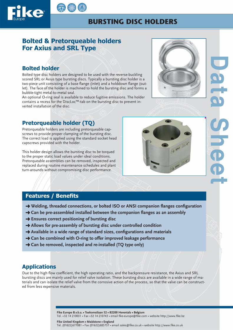
Bolted holderBolted type disc holders are designed to be used with the reverse-buckling scored SRL or Axius type bursting discs. Typically a bursting disc holder is a two-piece unit consisting of a base fl ange (inlet) and a holddown fl ange (out-let). The face of the holder is machined to hold the bursting disc and forms a bubble-tight metal-to-metal seal.An optional O-ring seal is available to reduce fugitive emissions. The holder contains a recess for the DiscLoc™-tab on the bursting disc to prevent in-verted installation of the disc.
Pretorqueable holder (TQ)Pretorqueable holders are including pretorqueable cap-screws to provide proper clamping of the bursting disc. The correct load is applied using the standard socket head capscrews provided with the holder.
This holder design allows the bursting disc to be torqued to the proper static load values under ideal conditions. Pretorqueable assemblies can be removed, inspected and replaced during routine maintenance schedules and plant turn-arounds without compromising disc performance.
Fike Europe B.v.b.a. • Toekomstlaan 52 • B2200 Herentals • BelgiumTel. +32 14 210031 • Fax +32 14 210743 • email fi ke-europe@fi ke.com • website http://www.fi ke.be
Fike United Kingdom • Maidstone • EnglandTel. (01622)677081 • Fax (01622)685737 • email sales@fi ke.co.uk • website http://www.fi ke.co.uk
Features / Benefi ts
Welding, threaded connections, or bolted ISO or ANSI companion fl anges confi guration Can be pre-assembled installed between the companion fl anges as an assembly Ensures correct positioning of bursting disc Allows for pre-assembly of bursting disc under controlled condition Available in a wide range of standard sizes, confi gurations and materials Can be combined with O-ring to offer improved leakage performance Can be removed, inspected and re-installed (TQ type only)
ApplicationsDue to the high fl ow coeffi cient, the high operating ratio, and the backpressure resistance, the Axius and SRL bursting discs are mainly used for relief valve isolation. These bursting discs are available in a wide range of ma-terials and can isolate the relief valve from the corrosive action of the process, so that the valve can be construct-ed from less expensive materials.

All above data are subject to change without notice. They must not be used unless confi rmed in writing.
Fike Europe B.v.b.a. • Toekomstlaan 52 • B2200 Herentals • BelgiumTel. +32 14 210031 • Fax +32 14 210743 • email fi ke-europe@fi ke.com • website http://www.fi ke.be
Fike United Kingdom • Maidstone • EnglandTel. (01622)677081 • Fax (01622)685737 • email sales@fi ke.co.uk • website http://www.fi ke.co.uk
Confi guration 1
Dimensions Bolted HoldersSize (Inch) XL Assembly height (In.) XLO Assembly height (ln.) Dimensions
ANSI 150Outside diameter
ANSI 300Outside diameter
1 2-3/8 2-1/8 2-1/2 2-3/4
1-1/2* 2-3/8 2-1/8 3-1/4 3-5/8
2 3 2-1/16 4 4-1/4
3 3-3/4 2-1/16 5-1/4 5-3/4
4 4-9/16 2-7/16 6-3/4 7
6 6 2-3/4 8-5/8 9-3/4
8 7-9/16 3 10-7/8 12
10 NA NA 13-1/4 14-1/8
12 NA NA 16 16-1/2
Dimensions Bolted Holders
Note: for 1-1/2” SRL discs, please specify SRL Holder Model (different seat dimensions only)
Size (Inch) confi guration XL Assem-bly height
(inch)
XLO As-sembly height (inch)
Dimensions Capscrew size (inch)
ANSI 150 ANSI 300
ANSI 150 ANSI 300 A B A B
1 3 3 3-3/8 NA NA 4-1/4 NA 4-7/8 1/2
1-1/2* 1 1 2-5/8 2-1/8 3-1/4 4-1/4 3-5/8 4-1/4 3/8
2 1 2 3-7/16 2-5/8 4 5-1/4 NA 5-1/4 1/2
3 1 2 4-5/32 2-9/16 5-1/4 6-3/8 NA 6-3/8 1/2
4 2 2 4-3/4 2-3/4 NA 7-3/4 NA 7-3/4 1/2
6 2 3 6 2-13/16 NA 9-1/2 NA 9-3/4 1/2
8 2 3 7-9/16 3-1/16 NA 11-3/4 NA 12 1/2
10 2 3 NA NA NA 13-13/16 NA 14-1/8 1/2
12 3 3 NA NA NA 16 NA 16-1/2 1/2
Confi guration 2 Confi guration 3
8.2126.00.5

Page 1
SRX RUPTURE DISC
DESCRIPTIONFike SRX rupture disc is a reverse acting rupture disc with a cross scored design for use with vapor services only. These discs have many high performance characteristics that make them ideal for demanding applications such as the isolation of pressure relief valves.
FEATURES AND BENEFITS• SRX rupture discs have superior service life in heavily pulsating and cyclic duty when compared to forward acting (tension loaded) rupture discs. This is primarily due to the reverse buckling (compression loaded) design.• The SRX is designed to be non-fragmenting. The cross score confi guration controls the disc opening and enables the disc to rupture without fragmentation.• SRX discs will sustain process operating pressures as high as 90% of the marked disc rating, without premature failure due to metal fatigue.• The SRX will withstand full vacuum, or back pressure service in magnitudes equivalent to the stamped burst pressure.• SRX discs perform reliably even under less than ideal installation conditions due to their special seating confi guration.• 316/316L SST, Inconel® 600, Monel® 400, Nickel 200/201, and Hastelloy® C276 are available as standard materials of construction. Consult factory for other materials. • The DiscLoc™ locator tab prevents incorrect, inverted installation in the holder. Prominent fl ow arrows indicate the process fl ow direction during venting.
PRESSURE RELIEF VALVE APPLICATIONWhen SRX discs are used to isolate pressure relief valves, a combination capacity factor of 0.9 may be used. Higher combination capacity factors may be established by testing and certifi cation in accordance with the ASME Code, Section VIII, Div I. See Fike Technical Bulletin TB8103 for more information.
OPTIONS• Available with Tefl on® liner 450°F (232°C)• Polyurethane 250°F (121°C) and Tefl on 450°F (232°C) protective coatings also available• Standard O-rings are available in Viton with a maximum operating temperature of 450°F (232°C)
704 S. 10th Street · P.O. Box 610 · Blue Springs, Missouri 64013-0610 U.S.A. · (816) 229-3405 · (816) 229-4615 · www.fi ke.com
Form No. R.1.27.01-3
SRX Rupture Disc
Page 2
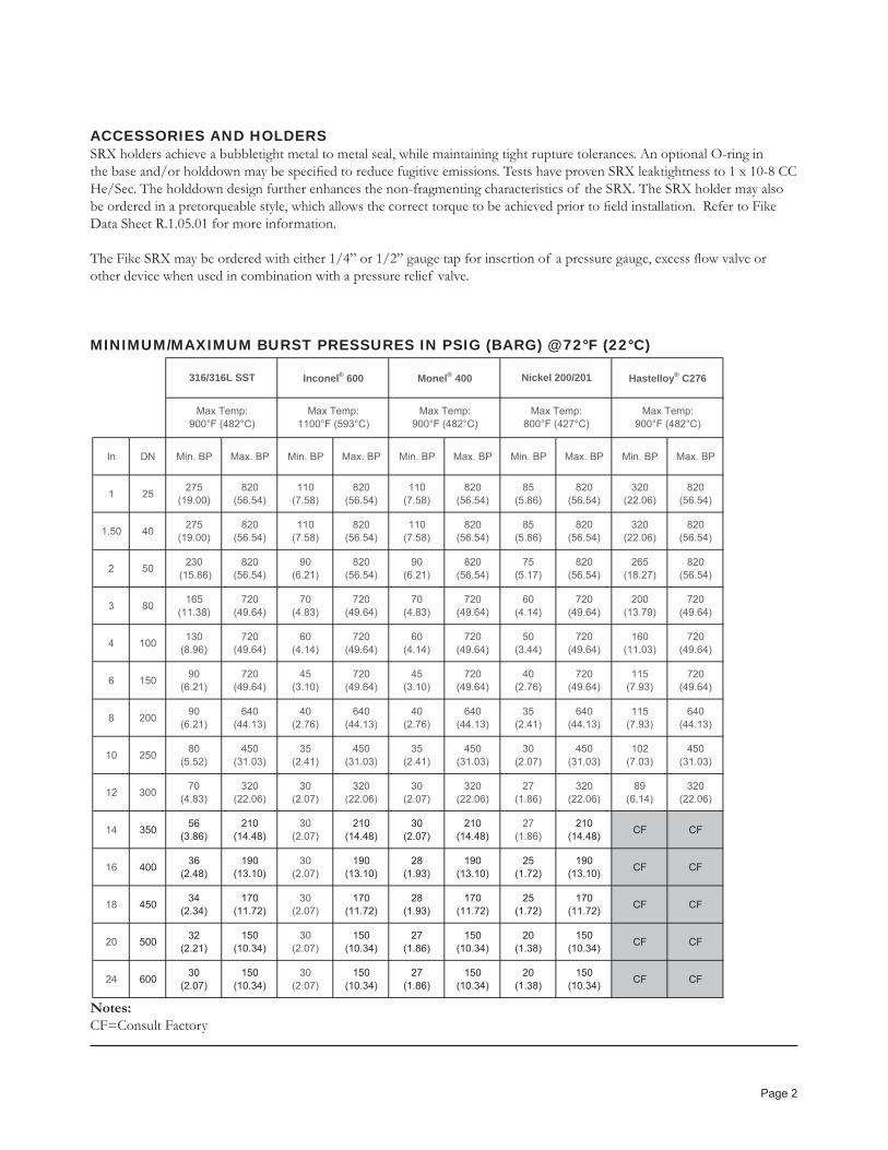
ACCESSORIES AND HOLDERSSRX holders achieve a bubbletight metal to metal seal, while maintaining tight rupture tolerances. An optional O-ring in the base and/or holddown may be specifi ed to reduce fugitive emissions. Tests have proven SRX leaktightness to 1 x 10⁻⁸ CC He/Sec. The holddown design further enhances the non-fragmenting characteristics of the SRX. The SRX holder may also be ordered in a pretorqueable style, which allows the correct torque to be achieved prior to fi eld installation. Refer to Fike Data Sheet R.1.05.01 for more information.
The Fike SRX may be ordered with either 1/4” or 1/2” gauge tap for insertion of a pressure gauge, excess fl ow valve or other device when used in combination with a pressure relief valve.
MINIMUM/MAXIMUM BURST PRESSURES IN PSIG (BARG) @ 72 °F (22°C)
Notes:CF=Consult Factory
In DN Min. BP Max. BP Min. BP Max. BP Min. BP Max. BP Min. BP Max. BP Min. BP Max. BP
1 25 275(19.00)
820(56.54)
110(7.58)
820(56.54)
110(7.58)
820(56.54)
85(5.86)
820(56.54)
320(22.06)
820(56.54)
1.50 40 275(19.00)
820(56.54)
110(7.58)
820(56.54)
110(7.58)
820(56.54)
85(5.86)
820(56.54)
320(22.06)
820(56.54)
2 50 230 (15.86)
820(56.54)
90(6.21)
820(56.54)
90(6.21)
820(56.54)
75(5.17)
820(56.54)
265(18.27)
820(56.54)
3 80 165(11.38)
720(49.64)
70(4.83)
720(49.64)
70(4.83)
720(49.64)
60(4.14)
720(49.64)
200(13.79)
720(49.64)
4 100 130(8.96)
720(49.64)
60(4.14)
720(49.64)
60(4.14)
720(49.64)
50(3.44)
720(49.64)
160(11.03)
720(49.64)
6 150 90(6.21)
720(49.64)
45(3.10)
720(49.64)
45(3.10)
720(49.64)
40(2.76)
720(49.64)
115(7.93)
720(49.64)
8 200 90(6.21)
640(44.13)
40(2.76)
640(44.13)
40(2.76)
640(44.13)
35(2.41)
640(44.13)
115(7.93)
640(44.13)
10 250 80(5.52)
450(31.03)
35(2.41)
450(31.03)
35(2.41)
450(31.03)
30(2.07)
450(31.03)
102(7.03)
450(31.03)
12 300 70(4.83)
320(22.06)
30(2.07)
320(22.06)
30(2.07)
320(22.06)
27(1.86)
320(22.06)
89(6.14)
320(22.06)
14 350 56(3.86)
210(14.48)
30(2.07)
210(14.48)
30(2.07)
210(14.48)
27(1.86)
210(14.48) CF CF
16 400 36(2.48)
190(13.10)
30(2.07)
190(13.10)
28(1.93)
190(13.10)
25(1.72)
190(13.10) CF CF
18 450 34(2.34)
170(11.72)
30(2.07)
170(11.72)
28(1.93)
170(11.72)
25(1.72)
170(11.72) CF CF
20 500 32(2.21)
150(10.34)
30(2.07)
150(10.34)
27(1.86)
150(10.34)
20(1.38)
150(10.34) CF CF
24 600 30(2.07)
150(10.34)
30(2.07)
150(10.34)
27(1.86)
150(10.34)
20(1.38)
150(10.34) CF CF
Hastelloy® C276 Nickel 200/201
Max Temp:800°F (427°C)
Max Temp:900°F (482°C)
Max Temp:900°F (482°C)
Monel® 400 Inconel® 600 316/316L SST
Max Temp:1100°F (593°C)
Max Temp:900°F (482°C)

Page 3
MINIMUM FREE VAPOR VOLUME
AVAILABLE MANUFACTURING RANGESAvailable
Manufacturing Ranges+0/-10%+0/-5%
Zero
BURST/PERFORMANCE TOLERANCEMarked Burst Pressure Tolerance
PSIG BARG PSIG BARG≤ 40 ≤ 2.76 ± 2 ± 0.14> 40 > 2.76 ± 5% ± 5%
HOW TO SPECIFYPrevious Lot Number:
ORSize:
Flange Rating: Burst Pressure: @ (Temperature)
Seal Material:Manufacturing Range: Std: Other:
Coatings:Optional O-Rings: Yes / No Qty:
Certifi cation: ASME CE
IN 1 1.5 2 3 4 6 8 10 12
DN 25 40 50 80 100 150 200 250 300
13 13 28 91 205 701 1,597 3,141 5,428
213 213 459 1,491 3,359 11,487 26,170 51,472 88,949
IN 14 16 18 20 22 24
DN 350 400 450 500 550 600
4.23 6.45 9.33 13.00 17.40 22.80
0.12 0.18 0.26 0.37 0.49 0.65
Size
Size
Cubic Inches (in3)
Cubic Centimiters (cm3)
Cubic Feet (ft3)
Cubic Meters (M3)

Page 4
Performance Attributes Process Media Rupture Disc Holders
Operating Ratio
Non-Fragmenting
Vacuum Resistant
Pulsating/Cyclic Liquid Vapor/Gas Bolted/Type Pre-Torque
90% yes yes yes no* yes yes yes
* Minimum vapor volume required - see table
CERTIFICATIONS
R
Copyright © Fike Corporation All Rights Reserved.Form No. R.1.27.01-3 June, 2009 Specifi cations are subject to change without notice.
UDASME Authorized
Specify When Ordering
BURSTING DISCS HOLDERS
Bolted type SRX
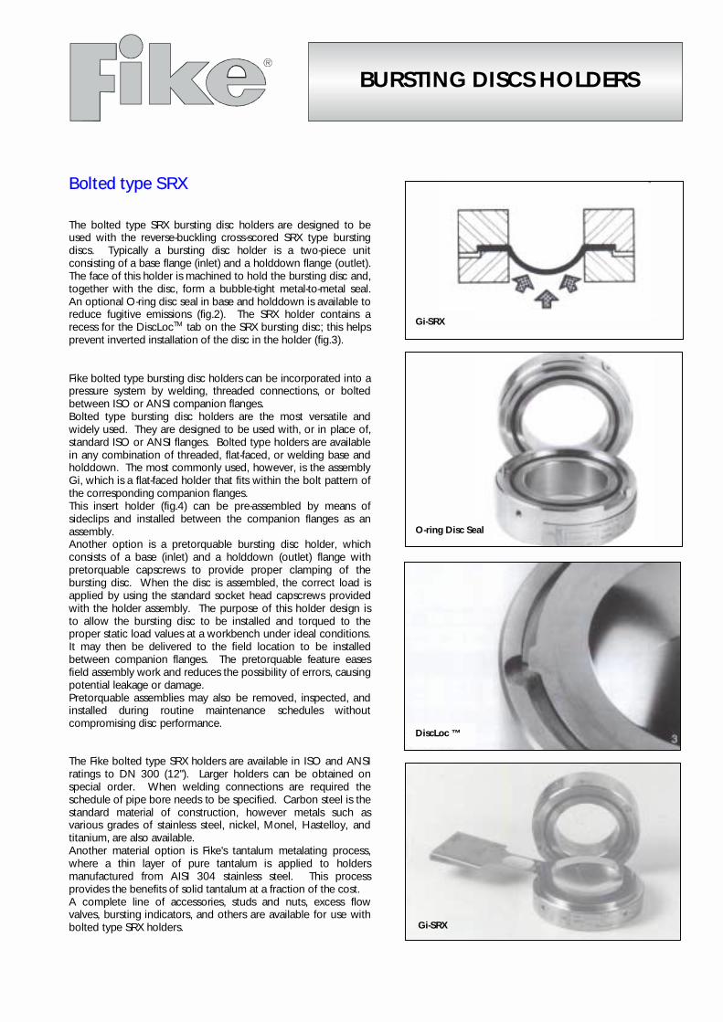
The bolted type SRX bursting disc holders are designed to beused with the reverse-buckling cross-scored SRX type burstingdiscs. Typically a bursting disc holder is a two-piece unitconsisting of a base flange (inlet) and a holddown flange (outlet).The face of this holder is machined to hold the bursting disc and,together with the disc, form a bubble-tight metal-to-metal seal.An optional O-ring disc seal in base and holddown is available toreduce fugitive emissions (fig.2). The SRX holder contains arecess for the DiscLocTM tab on the SRX bursting disc; this helpsprevent inverted installation of the disc in the holder (fig.3).
Fike bolted type bursting disc holders can be incorporated into apressure system by welding, threaded connections, or boltedbetween ISO or ANSI companion flanges.Bolted type bursting disc holders are the most versatile andwidely used. They are designed to be used with, or in place of,standard ISO or ANSI flanges. Bolted type holders are availablein any combination of threaded, flat-faced, or welding base andholddown. The most commonly used, however, is the assemblyGi, which is a flat-faced holder that fits within the bolt pattern ofthe corresponding companion flanges.This insert holder (fig.4) can be pre-assembled by means ofsideclips and installed between the companion flanges as anassembly.Another option is a pretorquable bursting disc holder, whichconsists of a base (inlet) and a holddown (outlet) flange withpretorquable capscrews to provide proper clamping of thebursting disc. When the disc is assembled, the correct load isapplied by using the standard socket head capscrews providedwith the holder assembly. The purpose of this holder design isto allow the bursting disc to be installed and torqued to theproper static load values at a workbench under ideal conditions.It may then be delivered to the field location to be installedbetween companion flanges. The pretorquable feature easesfield assembly work and reduces the possibility of errors, causingpotential leakage or damage.Pretorquable assemblies may also be removed, inspected, andinstalled during routine maintenance schedules withoutcompromising disc performance.
The Fike bolted type SRX holders are available in ISO and ANSIratings to DN 300 (12"). Larger holders can be obtained onspecial order. When welding connections are required theschedule of pipe bore needs to be specified. Carbon steel is thestandard material of construction, however metals such asvarious grades of stainless steel, nickel, Monel, Hastelloy, andtitanium, are also available.Another material option is Fike's tantalum metalating process,where a thin layer of pure tantalum is applied to holdersmanufactured from AISI 304 stainless steel. This processprovides the benefits of solid tantalum at a fraction of the cost.A complete line of accessories, studs and nuts, excess flowvalves, bursting indicators, and others are available for use withbolted type SRX holders.
Gi-SRX
Gi-SRX
DiscLoc ™
O-ring Disc Seal

8.2125.00.3
Fike Europe B.v.b.a. · Toekomstlaan 52 · B2200 Herentals · BelgiumTel. +32 14 210031 · Fax +32 14 210743 · email [email protected] · website http://www.fike.be
Fike United Kingdom · Maidstone · EnglandTel. (01622)677081 · Fax (01622)685737 · email [email protected] · website http://www.fike.co.uk
DIMENSIONS: Gi-SRX
All holders are provided with side clips
ANSI DIN Gi-SRX Approx.
BOLTS BOLTSINCH ANSI
Qty Ø in " L in "DN PN
Qty Size L in mm Ø DHeight
A±2 Ø B Ø CWeightin kg
1 150 4 1/2 4.75 25 6 4 M10 120 63 55 35.7 38.4 1.01 300 4 5/8 5.25 25 10-40 4 M12 120 70 55 35.7 38.4 1.2
1 1/2 150 4 1/2 5 82 55 35.7 38.4 1.840 6 4 M12 120 86 55 35.7 38.4 2.0
1 1/2 300 4 3/4 5.75 40 10-40 4 M16 130 92 55 35.7 38.4 2.42 150 4 5/8 5.75 101 57.5 59.3 63.9 2.32 300 8 5/8 6 50 10-40 4 M16 130 106 57.5 59.3 63.9 2.63 150 4 5/8 6 80 6 4 M16 130 132 57 83.0 89.3 3.5
80 10-40 8 M16 140 141 57 83.0 89.3 4.43 300 8 3/4 6.5 146 57 83.0 89.3 4.9
100 10-16 8 M16 150 162 65.5 106.5 114.7 5.7100 25-40 8 M20 160 166 65.5 106.5 114.7 6.2
4 150 8 5/8 6.25 171 65.5 106.5 114.7 6.94 300 8 3/4 7.25 177 65.5 106.5 114.7 7.76 150 8 3/4 7 150 10-16 8 M20 160 217 75 144.3 152.8 11.5
150 25-40 8 M24 180 224 75 144.3 152.8 12.96 300 12 3/4 7.75 247 75 144.3 152.8 18.0
200 10 8 M20 170 273 82.5 188.6 203.6 18.3200 16 12 M20 170 273 82.5 188.6 203.6 18.3
8 150 8 3/4 7.5 276 82.5 188.6 203.6 19.2200 25 12 M24 190 282 82.5 188.6 203.6 21.0200 40 12 M27 200 289 82.5 188.6 203.6 23.0
8 300 12 7/8 8.75 305 82.5 188.6 203.6 27.5250 6 12 M16 185 317 100 239.1 254.4 25.0250 10 12 M20 205 328 100 239.1 254.4 29.0250 16 12 M24 205 328 100 239.1 254.4 29.0
10 150 12 7/8 8.75 336 100 239.1 254.4 32.0250 25 12 M27 225 340 100 239.1 254.4 34.0250 40 12 M30 240 351 100 239.1 254.4 38.5
10 300 16 1 10.25 358 100 239.1 254.4 42.0300 6 12 M20 205 373 116 289.9 305.2 36.0300 10 12 M20 210 376 116 289.9 305.2 38.0300 16 12 M24 225 384 116 289.9 305.2 42.0300 25 16 M27 245 400 116 289.9 305.2 51.0
12 150 12 7/8 9.75 405 116 289.9 305.2 54.012 300 16 1 1/8 11.5 300 40 16 M30 265 417 116 289.9 305.2 61.0
All above data are subject to change without notice. They must not be used unless confirmed in writing.
BURSTING DISCS
Reverse bulged scoredType SR-H
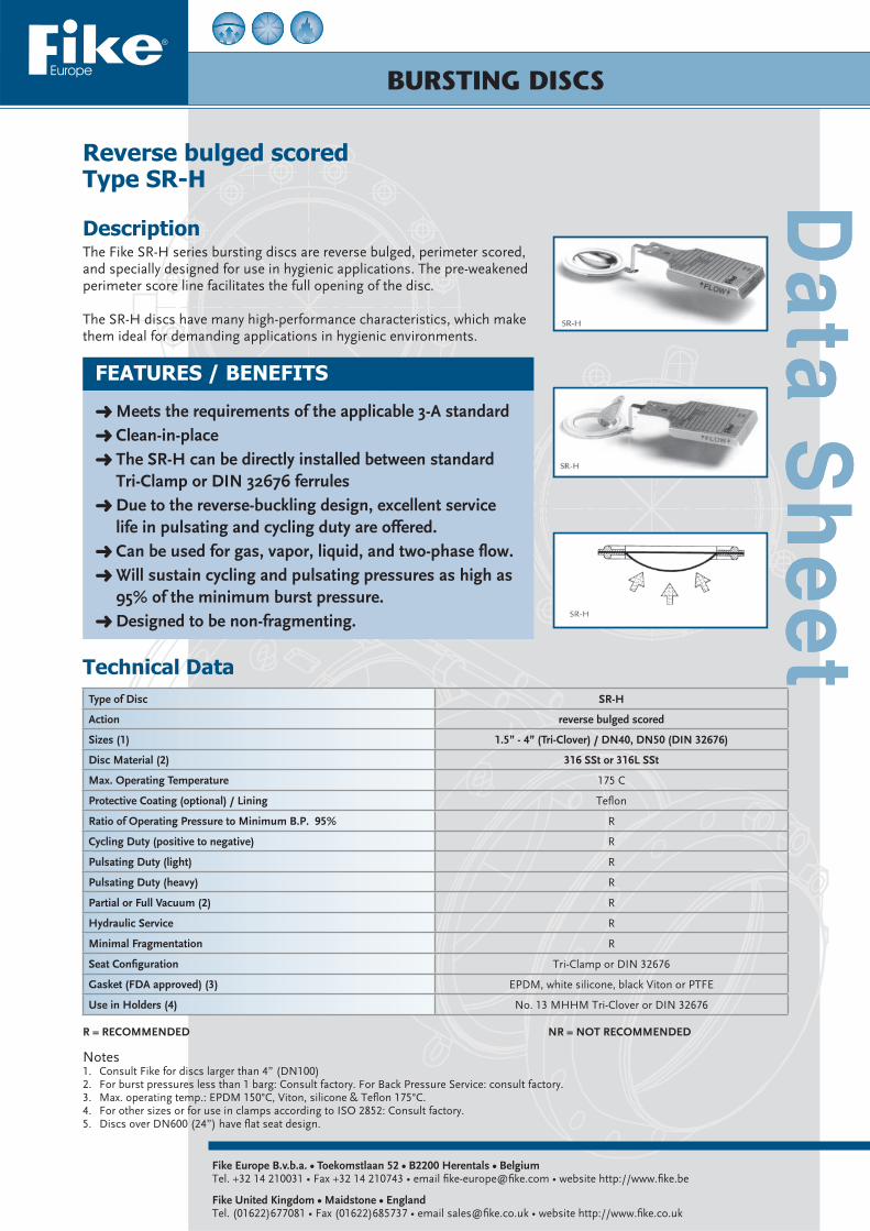
DescriptionThe Fike SR-H series bursting discs are reverse bulged, perimeter scored, and specially designed for use in hygienic applications. The pre-weakened perimeter score line facilitates the full opening of the disc.
The SR-H discs have many high-performance characteristics, which make them ideal for demanding applications in hygienic environments.
Fike Europe B.v.b.a. • Toekomstlaan 52 • B2200 Herentals • BelgiumTel. +32 14 210031 • Fax +32 14 210743 • email fi ke-europe@fi ke.com • website http://www.fi ke.be
Fike United Kingdom • Maidstone • EnglandTel. (01622)677081 • Fax (01622)685737 • email sales@fi ke.co.uk • website http://www.fi ke.co.uk
FEATURES / BENEFITS
Meets the requirements of the applicable 3-A standard Clean-in-place The SR-H can be directly installed between standard Tri-Clamp or DIN 32676 ferrules Due to the reverse-buckling design, excellent service life in pulsating and cycling duty are offered. Can be used for gas, vapor, liquid, and two-phase fl ow. Will sustain cycling and pulsating pressures as high as 95% of the minimum burst pressure. Designed to be non-fragmenting.
Technical DataType of Disc SR-H
Action reverse bulged scored
Sizes (1) 1.5” - 4” (Tri-Clover) / DN40, DN50 (DIN 32676)
Disc Material (2) 316 SSt or 316L SSt
Max. Operating Temperature 175 C
Protective Coating (optional) / Lining Tefl on
Ratio of Operating Pressure to Minimum B.P. 95% R
Cycling Duty (positive to negative) R
Pulsating Duty (light) R
Pulsating Duty (heavy) R
Partial or Full Vacuum (2) R
Hydraulic Service R
Minimal Fragmentation R
Seat Confi guration Tri-Clamp or DIN 32676
Gasket (FDA approved) (3) EPDM, white silicone, black Viton or PTFE
Use in Holders (4) No. 13 MHHM Tri-Clover or DIN 32676
Notes1. Consult Fike for discs larger than 4” (DN100)2. For burst pressures less than 1 barg: Consult factory. For Back Pressure Service: consult factory.3. Max. operating temp.: EPDM 150°C, Viton, silicone & Tefl on 175°C.4. For other sizes or for use in clamps according to ISO 2852: Consult factory.5. Discs over DN600 (24”) have fl at seat design.
R = RECOMMENDED NR = NOT RECOMMENDED

All above data are subject to change without notice. They must not be used unless confi rmed in writing. 8.1270.00.5
Fike Europe B.v.b.a. • Toekomstlaan 52 • B2200 Herentals • BelgiumTel. +32 14 210031 • Fax +32 14 210743 • email fi ke-europe@fi ke.com • website http://www.fi ke.be
Fike United Kingdom • Maidstone • EnglandTel. (01622)677081 • Fax (01622)685737 • email sales@fi ke.co.uk • website http://www.fi ke.co.uk
Burst Pressure in bargat 22°C
Performance Toleranceat 22°C
≤ 1.5 ± 0.15 barg
1.5 < burst pr. < 2.76 stand. ± 10% / red. ± 0.15 barg
≥ 2.76 stand. ± 10% / red. ± 5%
Performance tolerance as specifi ed by ISO/EN is a total tolerance which includes both manufacturing and burst tolerance.As per ISO/EN the bursting discs can be marked with:Specifi ed burst pressure with a performance tolerance (in % or a value).E.g.: 10 barg ±10% at 22°C (±1 barg).Maximum and minimum burst pressure.E.g.: Max 11barg at 22°C - min 9barg at 22°COn request bursting discs can be marked as per ASME code section VIII with the average burst test result and the burst tolerance of ±5% for burst pressures ≥ 2.76 barg (±0.15 barg for burst pressures < 2.76 barg).(*) Consult Fike for possibility to reduce tolerances.
Performance Tolerances (*)
Burst pressures in barg at 22°CSize Tri-Clamp 1 1/2” 2” 3” 4”
DIN 32676 40 50 N/A (2) N/A(2)
Burst Pressure 316 SSt or MIN 1.65 1.35 1.03 0.83
(Barg) 316L SSt(1) MAX 9.65 6.89 5.52 3.79
Notes1. Specify when ordering.2. Consult Fike.
Optional Burst Indicator The BC-H Burst indicator is specially designed for use with the SR-H Hygienic service-bursting disc. It provides instantaneous notifi cation of bursting and can be used to activate alarm, remote annunciators or interfaces with proc-ess control systems. The BC-H Burst indicator is installed downstream of the SR-H bursting discs.
ApplicationsThe Fike SR-H bursting disc is ideal for a wide range of hygienic applications: Food and beverage processing, phar-maceutical manufacturing, biotechnology, and anywhere a clean-in-place bursting disc is appropriate.

BURSTING DISCS
Reverse-acting with knifebladesType MRK
Fike Europe B.v.b.a. • Toekomstlaan 52 • B2200 Herentals • BelgiumTel. +32 14 210031 • Fax +32 14 210743 • email fi ke-europe@fi ke.com • website http://www.fi ke.be
Fike United Kingdom • Maidstone • EnglandTel. (01622)677081 • Fax (01622)685737 • email sales@fi ke.co.uk • website http://www.fi ke.co.uk
Features / Benefi ts
the 3-sweep knifeblade design offers lower bursting pressures for a specifi c material will in all cases withstand backpressures in excess of its operating ratio of 95% the predetermined bursting patterns of the knifeblade design allows a non fragmenting opening of the disc the disc is generally 3 to 5 times thicker than the stan-dard conventional forward-acting disc of the same ma-terial and therefore offers better corrosion resistance.
DescriptionThe Fike MRK bursting disc is a reverse-acting disc that opens upon contact with a knifeblade assembly. The holder holddown fl ange or outlet contains a knifeblade assembly which faces the concave side of the bursting disc. Once reversal pressure is reached, the crown of the disc is reversed and the disc comes in contact with the knifeblade assembly and is cut open, providing instant pressure relief.
Technical DataType of Disc MRK
Action reverse-acting with knifeblades
Dimensions (1) 1”-44” DN25-DN1100
Disc Material SSt Nickel Monel Inconel
Max. Operating Temperature 315°C 400°C 425°C 540°C
Protective Coating (2) Yes
Operating Ratio 95% R R R R
Cycling Duty R R R R
Pulsating Duty (light) R R R R
Pulsating Duty (heavy) R R R R
Partial or Full Vacuum R R R R
Polymerisation Processes NR NR NR NR
Hydraulic Service (3) MC MC MC MC
Non Fragmentation (4) R R R R
Seat Confi guration Flat
Use in Flanged Holders Type BT Yes
Use in Union Type Holders Type UT No
Use in Screw Type Holders Type ST No
Notes1. Consult Fike for discs > 24” (DN600).2. Maximum temperature for various coatings: Urethane Acrylic 65°C, Urethane 120°C, Tefl on 230°C.3. Reverse-acting bursting discs always need a minimum vapour volume to assure proper and complete opening (consult table 2 for minimum
values) and should not be used for hydraulic service.4. Specify when ordering.
R = RECOMMENDED MC = MARGINAL CONDITIONS NR = NOT RECOMMENDED

All above data are subject to change without notice. They must not be used unless confi rmed in writing. 8.1300.00.3
Fike Europe B.v.b.a. • Toekomstlaan 52 • B2200 Herentals • BelgiumTel. +32 14 210031 • Fax +32 14 210743 • email fi ke-europe@fi ke.com • website http://www.fi ke.be
Fike United Kingdom • Maidstone • EnglandTel. (01622)677081 • Fax (01622)685737 • email sales@fi ke.co.uk • website http://www.fi ke.co.uk
Burst Pressure in bargat 22°C
Performance Toleranceat 22°C
≤ 1.5 ± 0.15 barg
1.5 < burst pr. < 2.76 stand. ± 10% / red. ± 0.15 barg
≥ 2.76 stand. ± 10% / red. ± 5%
Performance tolerance as specifi ed by ISO/EN is a total tolerance which includes both manufacturing and burst tolerance.As per ISO/EN the bursting discs can be marked with:Specifi ed burst pressure with a performance tolerance (in % or a value).E.g.: 10 barg ±10% at 22°C (±1 barg).Maximum and minimum burst pressure.E.g.: Max 11barg at 22°C - min 9barg at 22°COn request bursting discs can be marked as per ASME code section VIII with the average burst test result and the burst tolerance of ±5% for burst pressures ≥ 2.76 barg (±0.15 barg for burst pressures < 2.76 barg).(*) Consult Fike for possibility to reduce tolerances.
Performance Tolerances (*)
Burst pressures in barg at 22°C (1) (2)DiscMaterial
Max.Temp.°C
Bursting Disc Size
ANSI 1” 1½” 2” 3” 4” 6” 8” 10” 12” 14” 16” 18” 20” 24”
DN 25 40 50 80 100 150 200 250 300 350 400 450 500 600
AISI 316Stainless Steel
315 Min 4.1 2.4 1.9 1.7 1.4 1.0 0.8 0.7 0.5 0.5 0.4 0.3 0.3 0.3
Max 99 69 69 69 69 69 3.45 3.10 2.75 2.41 2.06 1.72 1.38 0.7
Nickel 400 Min 4.1 2.4 1.9 1.7 1.4 1.0 0.8 0.7 0.5 0.5 0.4 0.3 0.3 0.3
Max 99 69 69 69 69 69 3.45 3.10 2.75 2.41 2.06 1.72 1.38 0.7
Monel 425 Min 4.1 2.4 1.9 1.7 1.4 1.0 0.8 0.7 0.5 0.5 0.4 0.3 0.3 0.3
Max 99 69 69 69 69 69 3.45 3.10 2.75 2.41 2.06 1.72 1.38 0.7
Inconel 540 Min 4.1 2.4 1.9 1.7 1.4 1.0 0.8 0.7 0.5 0.5 0.4 0.3 0.3 0.3
Max 99 69 69 69 69 69 3.45 3.10 2.75 2.41 2.06 1.72 1.38 0.7
Min VesselFree Vapour Volume dm³(3)
12 12 12.5 27 50 110 190 300 430 585 770 970 1200 1750
Max.Relief Area cm² 5 11.4 21.7 47.7 81.9 187 323 510 729 890 1181 1510 1871 2742
Notes1. Minimum burst pressures given are for full opening. Consult Fike for lower burst pressures with partial opening.2. Maximum burst pressures given are non-fragmenting opening. For higher burst pressures consult Fike.
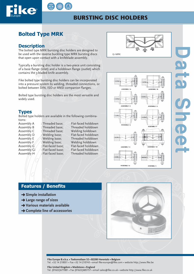
BURSTING DISC HOLDERS
Bolted Type MRK
DescriptionThe bolted type MRK bursting disc holders are designed to be used with the reverse buckling type MRK bursting discs that open upon contact with a knifeblade assembly.
Typically a bursting disc holder is a two-piece unit consisting of a base fl ange (inlet) and a holddown fl ange (outlet) which contains the 3-bladed knife assembly.
Fike bolted type bursting disc holders can be incorporated into a pressure system by welding, threaded connections, or bolted between DIN, ISO or ANSI companion fl anges.
Bolted type bursting disc holders are the most versatile and widely used.
Fike Europe B.v.b.a. • Toekomstlaan 52 • B2200 Herentals • BelgiumTel. +32 14 210031 • Fax +32 14 210743 • email fi ke-europe@fi ke.com • website http://www.fi ke.be
Fike United Kingdom • Maidstone • EnglandTel. (01622)677081 • Fax (01622)685737 • email sales@fi ke.co.uk • website http://www.fi ke.co.uk
Features / Benefi ts
Simple installation Large range of sizes Various materials available Complete line of accessories
TypesBolted type holders are available in the following combina-tions:Assembly A : Threaded base; Flat-faced holddownAssembly B : Threaded base; Threaded holddownAssembly C : Threaded base; Welding holddownAssembly D : Welding base; Flat-faced holddownAssembly E : Welding base; Threaded holddownAssembly F : Welding base; Welding holddownAssembly G : Flat-faced base; Flat-faced holddownAssembly Gi : Flat-faced base; Flat-faced holddownAssembly H : Flat-faced base; Threaded holddown

All above data are subject to change without notice. They must not be used unless confi rmed in writing. 8.2130.00.3
Fike Europe B.v.b.a. • Toekomstlaan 52 • B2200 Herentals • BelgiumTel. +32 14 210031 • Fax +32 14 210743 • email fi ke-europe@fi ke.com • website http://www.fi ke.be
Fike United Kingdom • Maidstone • EnglandTel. (01622)677081 • Fax (01622)685737 • email sales@fi ke.co.uk • website http://www.fi ke.co.uk
DIMENSIONS: Gi MRKNote: All holders marked with (*) are provided with sideclips, all others are provided with stainless steel preassembly screws.
ANSI DIN Gi-MRK approx. weight in kgINCH ANSI BOLTS DN PN BOLTS Ø D height
A±2 Ø Base
BØ HD
Cqty Ø in ” L in ” qty Ø L in mm
1 150 4 1/2 4.50 25 6 4 M10 110 63 49 25.5 25.0 1.10
1 300/600 4 5/8 5.50 25 10-40 4 M12 120 70 49 25.5 25.0 1.40
25 64-100 4 M16 140 81 49 25.5 25.0 1.90
1 1/2 150 4 1/2 4.75 82 52 38.2 35.9 1.80
40 6 4 M12 115 86 52 38.2 35.9 2.00
1 1/2 300/600 4 3/4 6.25 40 10-40 4 M16 130 92 52 38.2 35.9 2.35
40 64-100 4 M20 155 101 52 38.2 35.9 2.95
* 2 150 4 5/8 5.50 101 55 63.6 60.8 2.20
* 2 300/600 8 5/8 6.50 * 50 10-40 4 M16 140 106 55 63.6 60.8 2.60
* 50 64 4 M20 160 110 55 63.6 60.8 3.00
* 50 100 4 M24 170 117 55 63.6 60.8 3.50
* 3 150 4 5/8 6 * 80 6 4 M16 130 132 58.5 90.6 87.8 3.75
*80 10-40 8 M16 135 141 58.5 90.6 87.8 4.50
3 300/600 8 3/4 7.5 * 80 64 8 M20 160 146 58.5 90.6 87.8 4.90
* 80 100 8 M24 175 152 58.5 90.6 87.8 5.50
* 100 10-16 8 M16 145 162 64.5 116 111.6 3.50
* 100 25-40 8 M20 160 166 64.5 116 111.6 5.75
* 4 150 8 5/8 6 171 64.5 116 111.6 6.50
100 64 8 M24 175 174 74 116 111.6 7.80
4 300 8 3/4 7 177 64.5 116 111.6 7.30
100 100 8 M27 190 178 74 116 111.6 8.50
4 600 8 7/8 8.75 190 74 116 111.6 10.50
6 150 8 3/4 7.25 150 10-16 8 M20 170 217 80 154.9 149.9 11.60
* 150 25-40 8 M24 180 224 80 154.9 149.9 13.20
6 300 12 3/4 8 247 80 154.9 149.9 18.60
150 64 8 M30 230 247 93 154.9 149.9 21.50
150 100 12 M30 250 256 93 154.9 149.9 24.10
6 600 12 1 10.50 263 93 154.9 149.9 26.20
200 10 8 M20 190 273 99 203.4 196.5 20.70
200 16 12 M20 190 273 99 203.4 196.5 20.70
8 150 8 3/4 8.25 276 99 203.3 196.5 21.80
200 25 12 M24 210 282 99 203.3 196.5 24.00
200 40 12 M27 215 289 99 203.3 196.5 26.30
8 300 12 7/8 9.50 305 99 203.3 196.5 32.10
* 250 6 12 M16 205 317 118.5 261.7 254.7 24.00
* 250 10 12 M20 225 328 118.5 261.7 254.7 29.00
* 250 16 12 M24 225 328 118.5 261.7 254.7 29.00
10 150 12 7/8 9 336 118.5 261.7 254.7 33.00
250 25 12 M27 260 340 136.5 261.7 254.7 57.00
250 40 12 M30 275 351 136.5 261.7 254.7 61.00
10 300 16 1 11.5 358 136.5 261.7 254.7 50.70
300 6 12 M20 225 373 131 305.0 297.8 38.00
300 10 12 M20 230 376 131 305.0 297.8 40.00
300 16 12 M24 240 384 131 305.0 297.8 45.00
12 150 12 7/8 10 405 131 305.0 297.8 59.00

BURSTING DISCS
Flat Composite DiscsType AD, ADV, ADV-RI, AD-H
Fike Europe B.v.b.a. • Toekomstlaan 52 • B2200 Herentals • BelgiumTel. +32 14 210031 • Fax +32 14 210743 • email fi ke-europe@fi ke.com • website http://www.fi ke.be
Fike United Kingdom • Maidstone • EnglandTel. (01622)677081 • Fax (01622)685737 • email sales@fi ke.co.uk • website http://www.fi ke.co.uk
Features / Benefi ts
No holder required Compact design Torque / installation insensative Good corrosion resistance
Available TypesGeneral Purpose - Model ADThe basic AD Series Bursting Disc will offer controlled burst pressure throughout a wide range of sizes and pressures without the need for using a holder.
Vacuum Service - Model ADVThe ADV Series Bursting Disc has the same burst characteristics as the AD, but in addition it provides full vacuum resistance throughout the entire range .
Rupture Indicator - Model ADV-RIThe bursting of a low-pressure disc will often go unno-ticed, especially when it is used for sealing atmospheric vessels. Similarly when low pressure bursting discs are used to isolate safety valves from downstream conditions it may be diffi cult to detect that the disc has burst as the relief valve will reseat when pressure returns to normal conditions.In order to solve this problem an AD type disc is avail-able with a built-in bursting indicator.
Hygienic Service - Model AD-HFor applications where the process requires smooth sur-faces, the model AD-H offers an outstanding solution.
ApplicationsThe Fike AD Series bursting discs are used for sealing atmospheric vessels to eliminate environmentally harm-ful emissions and to protect them against slight over- or vacuum pressures. The AD Series discs are also used to isolate the atmospheric side of safety relief valves in order to protect them from downstream conditions
AD
ADV-RI
AD Disc
Bu
rsti
ng
D
isc
AD Disc
PRIMARY RELIEF
DOWNSTREAM RELIEF VALVE
DescriptionThe Fike AD Series Bursting Discs are low-pressure relief devices, pecifi cally designed for overpressure protection of atmospheric vessels and for isolating equipment such as safety relief valves from downstream conditions. The fl at composite discs consist of several component parts, which form a single unit. The design principle used to ensure a predictable bursting pressure is a tension failure of a mechanically weakened top section.

Technical dataTypte of Disc AD AD-H ADV ADV-RI Action Forward-actingAvailable Size Range 1”-24” (DN25-DN600) 1,5”-12” (DN40-DN300)
Material
Gasket (1) Non-Asbestos Non-Asbestos Non-Asbestos Non-AsbestosTop Section (2) SSTTop Alignment Ring (2) SSTSeal Tefl onBottom (2) SST - - -Vacuum Support (2) - - SST SSTRetaining Ring (2) - - SST SSTGasket (1) Non-Asbestos Non-Asbestos Non-Asbestos Non-Asbestos
Max. Operating Temperature 260°C 180°C 260°C 260°COperating Ratio 55%Same Burst Pressure both Directions (3) No No No NoRupture Indicator No No No YesMax. Voltage - - - 24V AC/DCMax. Current - - - 50mAMax. Resistance before Bursting - - - 30 OhmMax. Ambient Temperature - - - 80°CCycling Duty (pos. to neg.) MCPulsating Duty (light) RPulsating Duty (heavy) MCFull or Partial Vacuum Rating Partial NR Full FullPolymerisation Process NR R NR NRHydraulic Service RMinimal Fragmentation (4) RSeat Confi guration FlatUse betweenStandard Flanges
ANSI 150 YesPN10/16 (EN/ISO/DIN) Yes
Burst Pressure in mbarg at 22°C (1)
All above data are subject to change without notice. They must not be used unless confi rmed in writing. 8.1500.00.4
Fike Europe B.v.b.a. • Toekomstlaan 52 • B2200 Herentals • BelgiumTel. +32 14 210031 • Fax +32 14 210743 • email fi ke-europe@fi ke.com • website http://www.fi ke.be
Fike United Kingdom • Maidstone • EnglandTel. (01622)677081 • Fax (01622)685737 • email sales@fi ke.co.uk • website http://www.fi ke.co.uk
Size DN 25 40 50 65 80 100 125 150 200 250 300 350 400 450 500 600Inch 1 1 ½ 2 2 ½ 3 4 5 6 8 10 12 14 16 18 20 24
Minimum Burst Pressure mbar
AD, AD-H (3), ADV(2)
1815 515 355 230 160 245 160 125 50 40 35 35 35 35 50 40
ADV-RI N/A 800 600 500 430 350 300 260 210 175 160 - - - - -Max. B.P. in barg
All 10 10 6 3 2.0 1.5 1.5 1.3 1.3 1.3 1.3 1.3 1.3 1.0 1.0 1.0
Relief Area cm2 AD, AD-H 3,4 9,6 14.9 25.2 38.7 70.4 120.8 169 298.6 480.7 693.7 858.4 1142.5 1467.1 1832.2 2684.2ADV, ADV-RI N/A 7.1 13.9 22.1 34.7 65.8 115 161.7 286.5 461.9 615.8 - - - - -
Nominal BP ≤ 250 mbarg: ± 25 mbar
250 mbarg < Nominal BP ≤ 500 mbarg : ± 50 mbar
500 mbarg < Nominal BP ≤ 700 mbarg : ± 70 mbar
Nominal BP > 700 mbarg : ± 10%
Performance tolerance as specifi ed by ISO/EN is a total tolerance which includes both manufacturing and bursting tolerance.As per ISO/EN the bursting discs can be marked with:• Specifi ed burst pressure with a performance tolerance (in % or a value). E.g.: 10barg at 22°C ± 10% (± 1 barg).• Maximum and minimum burst pressure. E.g.: Max 11barg at 22°C - min 9barg at 22°COn request bursting discs can be marked as per ASME code section VIII with the average burst test result and the bursting tolerance of ± 5% for burst pressures ≥ 2.76barg, (0.15barg for burst pressures < 2.76 barg).(*) Consult Fike for possibility to reduce tolerances.
Performance Tolerances (*)
Notes1. If AD series bursting discs are used in combination with other types of bursting discs, the bursting pressure of the AD type disc should be
suffi ciently lower than the minimum relief pressure of the upstream disc to ensure proper functioning.2. ADV not available for DN25/1“ & sizes > DN3003. AD-H not available for sizes > DN250
Notes1. Notes1. Standard gaskets are asbestos-free. Other materials (such as Tefl on) can be supplied on request.2. Standard material of construction is AISI 300 series stainless steel (AISI 316L and/or AISI 304). Other materials are available on request.3. Same burst pressure both directions : consult factory.4. The AD series bursting discs will, subject to rates of pressure rise, give minimal fragmentation of the metallic parts. Tefl on seal, however, may
be ejected.
R = RECOMMENDED MC = MARGINAL CONDITIONS NR = NOT RECOMMENDED
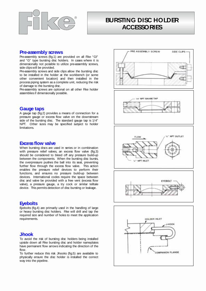
BURSTING DISC HOLDERACCESSORIES
Pre-assembly screwsPre-assembly screws (fig.1) are provided on all Fike “GI”and “G” type bursting disc holders. In cases where it isdimensionally not possible to utilize pre-assembly screws,side clips will be provided.Pre-assembly screws and side clips allow the bursting discto be installed in the holder at the workbench (or someother convenient location) and then installed in theprocess piping system as a complete unit, reducing the riskof damage to the bursting disc.Pre-assembly screws are optional on all other Fike holderassemblies if dimensionally possible.
Gauge tapsA gauge tap (fig.2) provides a means of connection for apressure gauge or excess flow valve on the downstreamside of the bursting disc. The standard gauge tap is 1/4”NPT. Other sizes may be specified subject to holderlimitations.
Excess flow valveWhen bursting discs are used in series or in combinationwith pressure relief valves, an excess flow valve (fig.3)should be considered to bleed off any pressure build-upbetween the components. When the bursting disc bursts,the overpressure pushes the ball into its seat, preventingfurther flow through the excess flow valve. This actionenables the pressure relief devices to perform theirfunctions, and ensures no pressure build-up betweendevices. International codes require the space betweendisc and valve be provided with a free vent (excess flowvalve), a pressure gauge, a try cock or similar telltaledevice. This permits detection of disc bursting or leakage.
EyeboltsEyebolts (fig.4) are primarily used in the handling of largeor heavy bursting disc holders. Fike will drill and tap therequired size and number of holes to meet the applicationrequirements.
J-hookTo avoid the risk of bursting disc holders being installedupside down all Fike bursting disc and holder nameplateshave permanent flow arrows indicating the direction of theflow.To further reduce this risk J-hooks (fig.5) are available tophysically ensure the disc holder is installed the correctway into the pipeline.

Fike Europe B.v.b.a. · Toekomstlaan 52 · B2200 Herentals · BelgiumTel. +32 14 210031 · Fax +32 14 210743 · email [email protected] · website http://www.fike.be
Fike United Kingdom · Maidstone · EnglandTel. (01622)677081 · Fax (01622)685737 · email [email protected] · website http://www.fike.co.uk
8.2800.00.2
Baffle plateA baffle plate (fig.6) should be considered when a bursting discassembly is free vented to the atmosphere. Its function is toredirect the discharge and absorb recoil, helping to protectpersonnel and surrounding equipment. Care must be taken toensure that the baffle plate design allows for adequate relief area.
JackscrewsThe use of jackscrews provides a means of separating pipingflanges to allow for safe and easy installation of fragile burstingdiscs or pre-assembled “G” or “Gi” holders. Jackscrews are usedonly with the bolted type series of bursting disc holders. There arethree methods of application that allow for differences in holderconfiguration.Figure 7 illustrates the “assembly F” showing that when studs andnuts are removed and the jackscrews are screwed down, theholder will separate. This allows easy installation and removal ofthe bursting disc.
Figure 8 illustrates the “assembly G insert” utilizing jackscrews. Asshown, holes must be drilled and tapped in the outlet companionflange at two places 180° apart to accept the jackscrews.
Figure 9 illustrates the “assembly G” utilizing jackscrews. For thismethod of application a threaded lug and pad must be welded tothe companion flanges (as shown), at two places 180° apart.
All above data are subject to change without notice. They must not be used for construction unless confirmed in writing.

ENGINEERED BURSTING DISCS
IntroductionA bursting disc assembly is a non-reclosing pressure relief device designed toprovide an instantaneous unrestricted relief opening to a closed system at apredetermined pressure. They can be considered as single use valvemechanisms with the following unique features:
• leak-tight seal until activation;• open/rupture in a predictable and controlled manner when the
defined activation conditions are present..
Engineered bursting disc products surpass the requirements of conventionalbursting disc devices manufactured for the chemical and petrochemicalindustries.Flexibility of design, a wide choice of materials, and suitability for narrow-tolerance critical uses make these devices the ideal solution for a wide range ofsealing, venting, one-time valving, or pressure relief requirements.
Four Advantages of Bursting Discs• Reliable – Due to their simple operation and lack of moving parts, bursting discs can be designed to withstand severe
operating conditions without affecting their performance.• Responsive – Bursting discs can provide full, unrestricted opening with millisecond response time.• Range – Bursting discs having burst diameters as small as 1/8” (DN 4) and as large as 68” (DN 1800) have been
manufactured. Custom sizes are available to meet specific needs. Materials of construction include a wide range ofstandard and exotic materials.
• Record – Bursting discs represent a well-developed technology which has been used with great success in theaerospace, aviation, defense, and nuclear industries for over 55 years.
Scope of Performance Capabilities• Depending on the size, flow and material of construction, discs can be offered with burst pressure down to 0,03 barg and up to
690 barg.• Back Pressure: Patented Fike designs allow backpressure several times the rated burst pressure.• Operating Temperature: -195°C to 1000°C with special heat reduction; design temperatures may be higher.• Burst Tolerance: +/- 5% is typical with +/- 2% possible in certain configurations• Non-Fragmentation: May be achieved in most configurations.• Critical Leakage: Most designs can meet a leakage requirement not to exceed 1 x 10⁻⁸ cc Helium/sec. (at one atmosphere
differential pressure)• Operating Pressure: May be as high as 90% of the disc rating.• Materials of Construction: Aluminium; Stainless Steel, Nickel, Monel®, Inconel®, Silver, Hastelloy® B&C, Titanium, Tantalum,
and Zirconium. Other materials possible subject to availability.• Response Time: Special designs may achieve opening in 1 millisecond or less.
DesignThe design process begins by gathering as much information about the application as possible. To determine the best solution forthese demanding or unique applications, Fike engineers consider many important factors: type of application, operating conditions,inlet/outlet configurations, bursting disc specifications, special processes, and testing requirements.Many engineered bursting disc products share some of the same basic requirements. These often include reduced burstingtolerances, vacuum service, helium leak-tight seal, stainless steel construction, and special inlet and outlet connections.Due to the critical nature of some applications, special testing procedures and equipment may be required to accurately simulateactual conditions or to investigate possible worst case scenarios. An Engineered Product Specification Sheet is found on the lastpage to help you provide the appropriate information about your application.

Typical Applications:
Refrigeration Valves:
A bursting disc is used to isolate refrigeration valves to preventleakage of refrigerant to the atmosphere. The leakage of suchrefrigeration products is not only the cause for additionalmaintenance or malfunction of the installation, but is also highlyrestricted by law due to toxic and/or environmental restrictions.Due to the superior leak-tightness offered by bursting discassemblies, combined with flexibility in configuration andmaterial selection, successful solutions can be found for suchapplications.
Electronic Industry:
Semiconductor manufacturing utilises special CO2-laser systemsto slice-cut silicon wafers. These wafers then become the core-element for IC-components used in today’s high-tech electronics.Bursting disc assemblies offer protection to these criticalmanufacturing systems from critical pressure surges in the CO2-gas supply and handling systems.
TOP VIEW
SECTION
BURST DIRECTION
TOP VIEW
TOP VIEW
SECTION
BURST DIRECTION

Gas Sampling & Storage Containers:
Material sampling of process media is an industrystandard practice to monitor product quality and output.Sampling containers (small-specialised pressure vessels)are used by the process operators or dedicatedpersonnel to remove the samples from the process.Bursting disc assemblies are used on the shut-off valvesof these sampling containers and prevent the operatorfrom accidentally overpressurising the containers. Similardevices are fitted to small gas storage cylinders toprevent overpressurisation.
Cryogenic Industries:
Cryogenic storage and production equipment, andcooling systems for large electromagnetic devices suchas CT-scanners often use high vacuum temperatureinsulating jackets (double wall vessels / pipe work) tokeep heat loss to a minimum. The outer shell of theseinsulating jackets are normally designed for full vacuumbut not high pressure, therefore some form of protectionis needed in case the inner pipe fails.Specially designed bursting disc assemblies can offer theessential long term vacuum integrity required for thistype of application, and the instant pressure reliefnecessary should there be a failure of the inner pipe.
SECTION
BURST DIRECTION
TOP VIEW
A A
TOP VIEW
SECTION
BURST DIRECTION

Fike Europe B.v.b.a. · Toekomstlaan 52 · B2200 Herentals · BelgiumTel. +32 14 210031 · Fax +32 14 210743 · email [email protected] · website http://www.fike.be
Fike United Kingdom · Maidstone · EnglandTel. (01622)677081 · Fax (01622)685737 · email [email protected]
8.1700.00.0
Engineered Product Specification Sheet
Project: Date:
I. GENERAL IV. RUPTURE DISCSPECIFICATION
1 Customer part number 20 Nominal size2 Fike drawing number 21 Type
II. DESIGN CONDITIONS 22 Non-fragmenting3 MAWP 23 Specified burst pressure4 Media 24 Manufacturing range5 Volume upstream of bursting disc 25 Rupture tolerance6 Volume downstream of bursting 26 Specified coincident temperature
disc or to atmosphere 27 Material7 Rate of pressure rise 28 Burst test at coincident temperature8 Operating pressure V. NON-DESTRUCTIVE TESTING
29 Leak rate requirements9 Operating temperature 30 Radiographic requirements10 Required relief area 31 Dye penetrant requirements11 Backpressure conditions VII. QUALITY CONTROL REQUIREMENTS12 Vacuum service 32 First article inspection13 Pulsating duty 33 Source inspection14 Cyclic duty 34 Qualification testing
III. BODY REQUIREMENTS 35 Lot acceptance testing15 Inlet connection VIII. SPECIAL PROCESSES16 Outlet connection 36 Cleaning Requirements17 Configuration requirements 37 Packaging requirements
38 Welding requirements18 Inlet Material 39 Special marking requirements19 Outlet Material 40 Passivation requirements
Typical Configurations
All above data are subject to change without notice. They must not be used unless confirmed in writing.
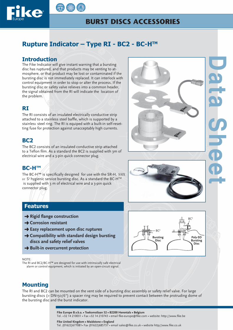
BURST DISCS ACCESSORIES
Rupture Indicator – Type RI - BC2 - BC-HTM
Fike Europe B.v.b.a. • Toekomstlaan 52 • B2200 Herentals • BelgiumTel. +32 14 210031 • Fax +32 14 210743 • email fi ke-europe@fi ke.com • website: http://www.fi ke.be
Fike United Kingdom • Maidstone • EnglandTel. (01622)677081• Fax (01622)685737 • email sales@fi ke.co.uk • website http//www.fi ke.co.uk
Features
Rigid fl ange construction Corrosion resistant Easy replacement upon disc ruptures Compatibility with standard design bursting discs and safety relief valves Built-in overcurrent protection
IntroductionThe Fike Indicator will give instant warning that a bursting disc has ruptured, and that products may be venting to at-mosphere, or that product may be lost or contaminated if the bursting disc is not immediately replaced. It can interlock with control equipment in order to stop or alter the process. If the bursting disc or safety valve relieves into a common header,the signal obtained from the RI will indicate the location of the problem.
RIThe RI consists of an insulated electrically conductive strip attached to a stainless steel baffl e, which is supported by a stainless steel ring. The RI is equiped with a built-in self-reset-ting fuse for protection against unacceptably high currents.
BC2The BC2 consists of an insulated conductive strip attached to a Tefl on fi lm. As a standard the BC2 is supplied with 3m of electrical wire and a 3-pin quick connector plug.
BC-H™The BC-H™ is specifi cally designed for use with the SR-H, SHXor S3 hygienic service bursting disc. As a standard the BC-HTM
is supplied with 3 m of electrical wire and a 3-pin quick connector plug.
BC2
BC2
Bursting Disc
Poly-SD Bursting
Disc
MountingThe RI and BC2 can be mounted on the vent side of a bursting disc assembly or safety relief valve. For large bursting discs (> DN150/6“) a spacer ring may be required to prevent contact between the protruding dome of the bursting disc and the burst indicator.
NOTE:The RI and BC2/BC-H™ are designed for use with intrinsically safe electrical
alarm or control equipment, which is initiated by an open-circuit signal.

All above data are subject to change without notice. They must not be used unless confi rmed in writing. 8.1800.00.5
Fike Europe B.v.b.a. • Toekomstlaan 52 • B2200 Herentals • BelgiumTel. +32 14 210031 • Fax +32 14 210743 • email fi ke-europe@fi ke.com • website: http://www.fi ke.be
Fike United Kingdom • Maidstone • EnglandTel. (01622)677081• Fax (01622)685737 • email sales@fi ke.co.uk • website http//www.fi ke.co.uk
Technical Data
Model RI BC2 BC-HTM
Confi guration Flat
Sizes DN25-DN300 / 1”-12” DN15-DN600 / ½”-24” DN40-DN100 / 1½ ”-4”
Material
Gasket (1) NonAsbestos Silicone (3)
Baffl e SST N/A
Conductor Cu-foil laminated between Kapton®-fi lm
Ring (2) SST
Seal N/A Tefl on®
Gasket (1) Non Asbestos Silicone (3)
Max. Process Temperature 260°C 175°C (3)
Max. Ambient Temperature 65°C
Max. Voltage 24VAC/DC
Max. Current 50mA
Max. Resistance before Rupture 30Ω 2Ω 2Ω
Electrical Cable
Length (4) 3m
Type 1x2x0,5mm2
Materials PVC shielded and insulated
Colour Blue
Max. Temp. 80°C
Electrical Connector N/A 3-PIN Quick-Disconnect
Alternative Cable length Optional 10m & 25m
Designed/certifi ed for use in Explosion Proof Electri-cal circuitry per EEx ia IIC T6 EEx ia IIB T6
Min/Max. Burst Pressures (barg) See Table 1 0,7 – 100 0,7 – 9,66
Use between Standard Flanges
ANSI 150/300/600 Yes Yes No
DIN 2631 through 2637 Yes Yes No
Triclamp-connection No No Yes
1. Standard gaskets are asbestos-free (AFM34) on RI and BC2 and Silicone on BC-HTM, however, other materials, such as Tefl on, can be supplied on request. Consult factory.
2. Standard material of construction is AISI 304 stainless steel (for BC2 & BC-H, 316L for RI). Other materials are available on request.3. Other materials, Viton or EPDM (max. temp. 150°C) are available on request.4. The BC2 and BC-HTM are supplied with 3m of cable which has a 3 Pin Plug and Socket fi tted approximately 300mm from the Burst
Indicator.
Table - Minimum ∆P required for functioning of RI
Size DN 25 40 50 65 80 100 125 150 200 250 300
Inch 1 1½ 2 2½ 3 4 5 6 8 10 12
Minimum ∆P required 2000 800 600 500 430 350 300 260 210 175 160
Relief area cm² 4,52 7,07 13,85 22,06 34,73 65,76 114,99 161,73 286,52 461,86 615,75
1. Subject to the rate of pressure rise, minimal fragmentation may occur.2. Minimum burst pressures BC2 : DN25 - DN80 í 0,7barg (Lower burst pressures are possible. Consult factory) DN100 - DN600 í no minimum burst pressures.

BURSTING DISCS
Fike Europe B.v.b.a. • Toekomstlaan 52 • B2200 Herentals • BelgiumTel. +32 14 210031 • Fax +32 14 210743 • email fi ke-europe@fi ke.com • website: http://www.fi ke.be
Fike United Kingdom • Maidstone • EnglandTel. (01622)677081• Fax (01622)685737 • email sales@fi ke.co.uk • website http//www.fi ke.co.uk
Features / Benefi ts
A passive device designed to give an instantaneous, unrestricted relief opening Mounted fl ush with the inner wall of the extruder barrel. Interchangeable with most pressure and temperature transducers used in extrusion machinery Burst diameters are available in ranges from DN4.5 to DN45. Larger sizes, up to DN150, can be provided on a spe-cial order basis. Materials of construction are stainless steel for the body with the bursting disc in AISI 316 stainless steel, nickel, Inconel or Monel.
Description
In the plastics processing industry, extrusion machin-ery is used in the production of many products, such as blown fi lm, profi le, sheet, tubing, pipe, rod, wire coat, fi bre spinning, and palletising. The plastic is molten and pumped into a die under pressure, gener-ated by a screw or a melt pump.High pressure is the basic parameter of the extrusion process and, therefore, safety is of paramount impor-tance. Special pressure transducers are used to moni-tor and control every stage of the extrusion process. The pressures are usually measured at the die, along the barrel, at the screen changer and the melt pump.Many reasons, such as loss of temperature control, foreign material, and clogged screens can result in excessive pressure build-up.Too much pressure can lead to excessive wear of the machinery and damage to the screen, die or extruder barrel.
Extruder Bursting DiscsType ERD

Dimensions (in mm)DWG No. Outlet DN A B C D E F Thread
636000 FreeDN 4.5 7.77 10.96 5.44 12.0 52 152.5 ½” – 20 UNF-2A
636001 1/4” NPT male
All above data are subject to change without notice. They must not be used unless confi rmed in writing. 8.1900.00.5
Fike Europe B.v.b.a. • Toekomstlaan 52 • B2200 Herentals • BelgiumTel. +32 14 210031 • Fax +32 14 210743 • email fi ke-europe@fi ke.com • website: http://www.fi ke.be
Fike United Kingdom • Maidstone • EnglandTel. (01622)677081• Fax (01622)685737 • email sales@fi ke.co.uk • website http//www.fi ke.co.uk
Standard Extruder Bursting DiscsFike has two models of microtig welded extruder bursting disc assemblies, designed to be interchangeable with Dynisco, Terwin, and Wicka pressure transducers.These can be supplied on short notice in a range of burst pressures from 80 to 1000bar at 530°C. Their nominal diameter is DN4.5.Model 636000 has a free outlet and model 636001 has a 1/4” NPT male threaded outlet connection.The standard length is 150mm but other dimensions are available on request.The standard material of construction is AISI 304 stainless steel for the body and Inconel for the bursting disc.The ratio of operating pressure to minimum burst pressure is 90%.Burst pressure tolerance: Standard +/- 10% Reduced +/- 5%
Mounting Hole Details (in mm) DWG No. Outlet A B C D E F Thread
636000 Free7.95±0.03 11.54±0.09 5.70 min 4.3 max 19 min 13.08 max ½”- 20 UNF-2B
636001 1/4” NPT male
Order InformationWhen ordering Fike ERD devices, specify model number, body confi guration, body and disc material, required burst pressure and temperature, operating pressure and temperature, and process media. When reordering, specify the serial number of the unit being replaced. If dimensions are other than specifi ed in table above, specify nominal diameter and dimensions A to E. For any further information, contact Fike or your local representative.

BURSTING DISC HOLDERS
Double Disc Safety Device
DescriptionDouble disc safety devices are typically used for environments involv-ing corrosive, toxic or high-value media. The double disc confi guration ensures that any loss of pressure or media through the fi rst bursting disc due to fatigue or corrosion will be captured by the second bursting disc, without affecting the required pressure relief condition.
In addition, the double disc assembly can be used as a fast-acting valve, by pressurising the space between the discs. On command, a solenoid valve can evacuate the pressure in the midfl ange causing both discs to rupture virtually instantaneously.
The double disc assembly is also useful in separation or testing of com-bustible material. Until needed, the fuel components are hermetically sealed from each other to avoid explosions. They can then be released to mix and ignite by planned overpressure.
Technical Data
Fike Europe B.v.b.a. • Toekomstlaan 52 • B2200 Herentals • BelgiumTel. +32 14 210031 • Fax +32 14 210743 • email fi ke-europe@fi ke.com • website: http://www.fi ke.be
Fike United Kingdom • Maidstone • EnglandTel. (01622)677081• Fax (01622)685737 • email sales@fi ke.co.uk • website http//www.fi ke.co.uk
Features / Benefi ts
Compact, leak-free design Reduces maintenance / emission costs Offers long-term controlled performance of critical safety systems Ideal for emergency (crash) cooling and inhibitor injection systems
ApplicationsIn some instances a bursting disc device may be located in an unmanned or remote position, where maintenance intervals must be maximised. With a double disc assembly under normal operating conditions, the sec-ond disc offers continued protection even after the fi rst disc has failed due to corrosion or fatigue. This results in a replacement of the failed bursting disc at the convenience of the plant or process, without having to undergo an emergency shutdown. Since both discs are normally set to operate at the same burst pressure and temperature, the service life is effectively doubled.
Standard Product RangeDouble disc safety devices are available as standard items in sizes from 1/2 inch/DN15 through 8 inches/DN200 in diameter. Larger sizes can be designed to suit particular requirements on an engineered basis. Discs are either of the conventional prebulged (forward acting), composite (forward acting), scored forward acting or reverse acting type.
8.2170.00.1
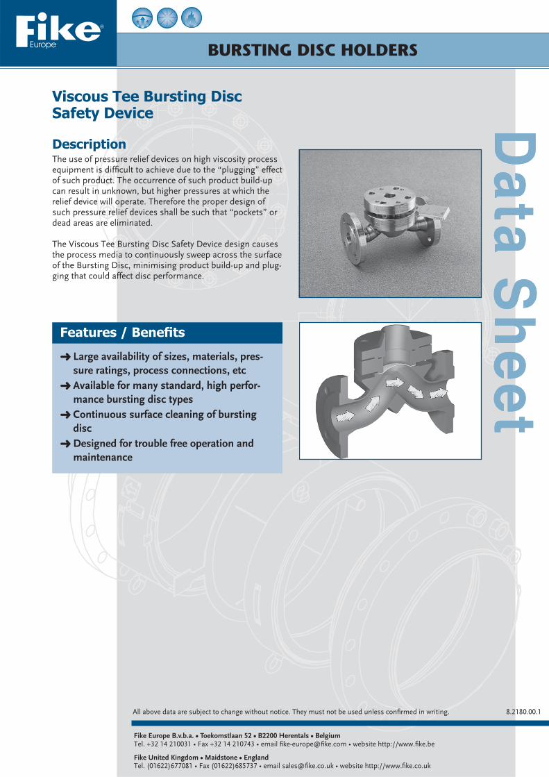
BURSTING DISC HOLDERS
Viscous Tee Bursting DiscSafety Device
DescriptionThe use of pressure relief devices on high viscosity process equipment is diffi cult to achieve due to the “plugging” effect of such product. The occurrence of such product build-up can result in unknown, but higher pressures at which the relief device will operate. Therefore the proper design of such pressure relief devices shall be such that “pockets” or dead areas are eliminated.
The Viscous Tee Bursting Disc Safety Device design causes the process media to continuously sweep across the surface of the Bursting Disc, minimising product build-up and plug-ging that could affect disc performance.
Fike Europe B.v.b.a. • Toekomstlaan 52 • B2200 Herentals • BelgiumTel. +32 14 210031 • Fax +32 14 210743 • email fi ke-europe@fi ke.com • website http://www.fi ke.be
Fike United Kingdom • Maidstone • EnglandTel. (01622)677081 • Fax (01622)685737 • email sales@fi ke.co.uk • website http://www.fi ke.co.uk
Features / Benefi ts
Large availability of sizes, materials, pres-sure ratings, process connections, etc Available for many standard, high perfor-mance bursting disc types Continuous surface cleaning of bursting disc Designed for trouble free operation and maintenance
All above data are subject to change without notice. They must not be used unless confi rmed in writing. 8.2180.00.1

! ! " #$% &'( %# )#&( *+ , -
!"#$%"&'& #. $/ $0 $ ' 1 2 $ !
3
&4
.4% ! /!(
4$.&
.& .. ./

56 '.6..(( 6
7/.&0.&((/&"7/.&0.&(80/9 4
:;< 5
*(&2..-288(=&"*(&2..-2='8/8 9
=&'&((((
$3
1 %/((
$ $$
$
6 $$
$
>>
<
1 %/((
<"+ .2(?+> '(@
$6 )
? >
) *- >
) *- #>
) #>
) ) #>
$ >
< <?
$?
#$%&'(A# : $ %#.2/.
>
<?
#>
( $ + * - , $ %$%/(( *%$%/&2 %$%/(0-+ , ! B !
!!B
# &(( &.' &'( .(( .'($3
% 0 ' 2 = &(
<6 ) . .0( .&( &8( &0(
<"6 ) 0
>C 8(0( &.(8 &2D( 'D=' 0=(0
) 7 &(@ ) %$+ ?5#
B
>
#>
/45"