kro 120 da 21304
DESCRIPTION
KELVIN MANUALTRANSCRIPT
7/17/2019 Kro 120 Da 21304
http://slidepdf.com/reader/full/kro-120-da-21304 1/75
KRO 90 – 200
MANUALE D’ISTRUZIONE
USER’S MANUAL
IT-GB

7/17/2019 Kro 120 Da 21304
http://slidepdf.com/reader/full/kro-120-da-21304 2/75
7/17/2019 Kro 120 Da 21304
http://slidepdf.com/reader/full/kro-120-da-21304 3/75
ITALIANO
1.1
INDICAZIONI IMPORTANTI PER LA SICUREZZA............................................................... ...............5 1.2 MOVIMENTAZIONE ED IMMAGAZZINAMENTO............................................................................ ..5
1.3 INSTALLAZIONE DEL REFRIGERATORE ....................................................... .................................... 6 1.4 USO PROPRIO DELL’UNITA’ .............................................................. ................................................... 7 1.5 FLUIDI AMMISSIBILI...............................................................................................................................7 1.6 COLLEGAMENTO IDRAULICO DELL’UNITA’........................................................................... .........8 1.6.1 Tipologie e riempimento dei circuiti....... ..................................................................... ............................9 1.7 ALLACCIAMENTO ELETTRICO DELL’UNITA’ ....................................................... ........................9 1.8 MESSA IN SERVIZIO..............................................................................................................................10 1.8.1 Regolazione della temperatura ................................................................... .......................................... 11 1.8.2 Regolazione della portata e della prevalenza................... ................................................................. ...11 1.8.3 Regolazione dell’allarme del flussostato (optionale)............................................................. ................12 1.9 UNITA’ PER ESTERNO...........................................................................................................................12 1.10 MANUTENZIONI E RIPARAZIONI................... ................................................................ ......................12 1.10.1 Manutenzione ordinaria................................................................. ...................................................... 12 1.10.2 Pulizia della batteria condensante................................................. ....................................................... 13 1.10.3 Pulizia della vasca ........................................................ ............................................................ .............13 1.10.4 Manutenzione straordinaria ............................................................................................................. ....13 1.11 RICERCA GUASTI E DIAGNOSI RAPIDA ................................................... ........................................ 14 1.12 MESSA FUORI SERVIZIO DELL’UNITA’............................................................................................15
ENGLISH
2.1 IMPORTANT SAFETY RELATED MEASURES...................................................................................17 2.2 TRANSPORT AND HANDLING............................................................................................................17 2.3 INSTALLATION OF THE CHILLER ......................................................... ............................................ 18 2.4 PROPER USE OF THE UNIT...................................................................................................................18 2.5 ALLOWED FLUIDS.................................................................................................................................19 2.6 HYDRAULIC PIPING OF THE UNIT.................................................................................................19 2.6.1 Types and filling up of the circuits................................................................................................................20 2.7 ELECTRICAL CONNECTION OF THE UNIT.................... ................................................................ ...21 2.8 START UP.................................................................................................................................................22 2.8.1 Temperature adjusting .............................................................. ............................................................ 22 2.8.2 Flow rate and pressure head adjusting.................. ................................................................ ...............23 2.8.3 Flow switch alarm adjusting (optional) .............................................................. ................................... 23 2.9 OUTDOOR UNITS................................................. ....................................................... ...........................23 2.10 MAINTENANCE AND REPAIR.................................................................................................. ............24 2.10.1 Ordinary Maintenance..........................................................................................................................24 2.10.2 Cleaning of the condensing coil............................................................................................................24 2.10.3 Cleaning of the tank...............................................................................................................................25 2 10 4 Extraordinary maintenance 25

7/17/2019 Kro 120 Da 21304
http://slidepdf.com/reader/full/kro-120-da-21304 4/75

7/17/2019 Kro 120 Da 21304
http://slidepdf.com/reader/full/kro-120-da-21304 5/75
1.1 INDICAZIONI IMPORTANTI PER LA SICUREZZA
Leggere attentamente le presenti istruzioni ed attenersi scrupolosamente alle prescrizioni
contenute nel manuale, in particolare a quelle d’ATTENZIONE nei riquadri ed in
grassetto. Il Costruttore rifiuta ogni responsabilità per danni a persone o cose conseguenti
la mancata osservanza delle prescrizioni.
1. Togliere sempre tensione prima di effettuare qualsiasi operazione d’ispezione, assistenza o
pulizia.
2. Impedire a personale non qualificato di manovrare, ispezionare o manomettere l’unità. Non
intervenire sul circuito frigorifero senza la presenza di un frigorista.
3. Non operare mai con fiamme libere all’interno dell’unità.
4. Non escludere le sicurezze elettriche e non forzare il funzionamento della macchina.
5. Non utilizzare l'unità per scopi differenti da quelli per cui è stata specificatamente
progettata.
6. Non installare il refrigeratore esposto alle intemperie o in atmosfera esplosiva/aggressiva.
7. Non posizionare l’unità su superfici instabili o non idonee a sopportarne il peso.
8. Conservare il presente manuale per consultazioni future.
1.2 MOVIMENTAZIONE ED IMMAGAZZINAMENTO
All’atto della spedizione i refrigeratori vengono imballati in scatola di cartone e spediti su pallet.
Al ricevimento controllare attentamente l’integrità dell’imballo e verificare l’assenza di danni
dovuti al trasporto. Ogni danno riscontrato deve essere evidenziato al corriere immediatamente
in forma scritta. Se si sospettano danni interni si consiglia di accettare la merce con riserva di
controllo denunciando il danno al corriere entro 8
giorni solari . Le unità devono essere

7/17/2019 Kro 120 Da 21304
http://slidepdf.com/reader/full/kro-120-da-21304 6/75
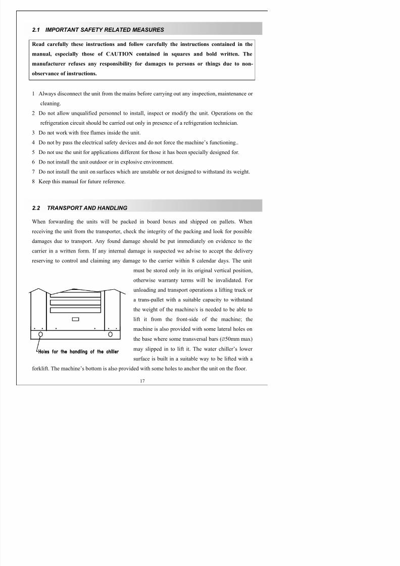
basamento per il sollevamento dove è possibile infilare delle barre trasversali (Ø50mm max). La
superficie inferiore del refrigeratore è costruita in maniera adeguata al sollevamento con muletto.
Sono predisposti anche dei fori sul fondo macchina per l’ancoraggio dell’unità al terreno.
KRO90 KRO120 KRO150 KRO160 KRO180 KRO200
PESO (kg) 222 232 242 248 258 268
DIMENSIONI
AxLxP (mm) 1260x615x1160 1260x615x1160 1260x615x1160 1260x715x1360 1260x715x1360 1260x715x1360
ATTENZIONE: durante tutte le operazioni di movimentazione e sollevamento assicurarsi
di aver saldamente ancorato l’unità per evitare ribaltamenti o cadute accidentali.
1.3 INSTALLAZIONE DEL REFRIGERATORE
Nella versione standard l’aria per il raffreddamento del condensatore viene aspirata lateralmente
da entrambi i lati e viene espulsa verso l’alto. Al momento dell’installazione è indispensabile
assicurarsi che l’aria espulsa non incontri ostacoli che determinino riduzioni delle portate e che
non venga riaspirata lateralmente.
Se nell’ambiente di utilizzo vi è alta concentrazione di polveri o sostanze oleose, accertarsi che
la macchina sia provvista di filtro d’aria o filtro antigrasso montato al posto di un pannello
laterale grigliato e con pannello opposto cieco.
Per l’installazione all’esterno l’unità deve essere stata ordinata appositamente per tale
esecuzione.
Durante il posizionamento lasciare uno spazio libero di almeno 800mm intorno a ciascun lato
dell’unità per le normali operazioni di manutenzione ordinaria e straordinaria. Evitare inoltre
l’accostamento a fonti di calore e sorgenti di polvere.
Su tutte le unità con vasca di accumulo e versione DP sono provviste di valvola meccanica di by-
d i di 1000 kP (10 b ) i d ll’i i
7/17/2019 Kro 120 Da 21304
http://slidepdf.com/reader/full/kro-120-da-21304 7/75
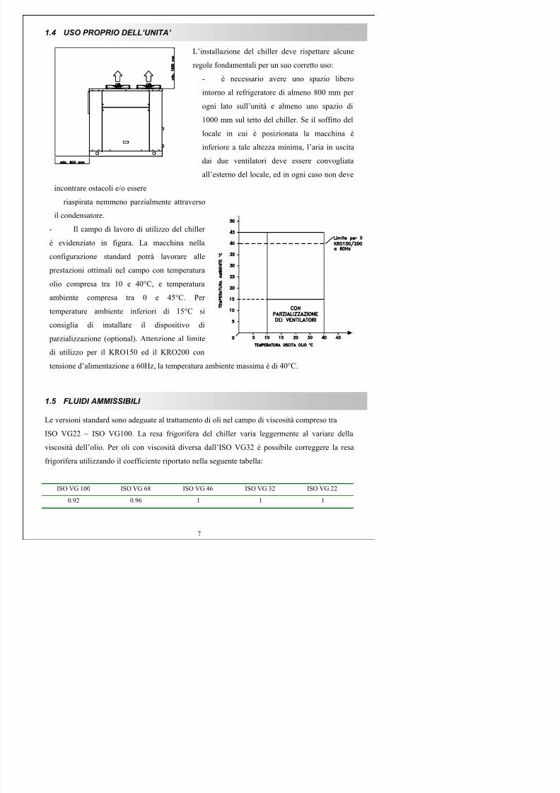
1.4 USO PROPRIO DELL’UNITA’
L’installazione del chiller deve rispettare alcune
regole fondamentali per un suo corretto uso:
- è necessario avere uno spazio libero
intorno al refrigeratore di almeno 800 mm per
ogni lato sull’unità e almeno uno spazio di
1000 mm sul tetto del chiller. Se il soffitto del
locale in cui è posizionata la macchina è
inferiore a tale altezza minima, l’aria in uscita
dai due ventilatori deve essere convogliata
all’esterno del locale, ed in ogni caso non deve
incontrare ostacoli e/o essere
riaspirata nemmeno parzialmente attraverso
il condensatore.
- Il campo di lavoro di utilizzo del chiller
è evidenziato in figura. La macchina nella
configurazione standard potrà lavorare alle
prestazioni ottimali nel campo con temperatura
olio compresa tra 10 e 40°C, e temperatura
ambiente compresa tra 0 e 45°C. Per
temperature ambiente inferiori di 15°C si
consiglia di installare il dispositivo di
parzializzazione (optional). Attenzione al limite
di utilizzo per il KRO150 ed il KRO200 con
tensione d’alimentazione a 60Hz, la temperatura ambiente massima è di 40°C.

7/17/2019 Kro 120 Da 21304
http://slidepdf.com/reader/full/kro-120-da-21304 8/75
1.6 COLLEGAMENTO IDRAULICO DELL’UNITA’
ATTENZIONE: Un fluido da raffreddare con portate e temperature non previste provocal’intervento degli automatismi sia elettrici che frigoriferi. Forzare il funzionamento è
pericoloso per l’incolumità delle persone e dannoso per l’unità.
Si consiglia di installare una valvola di by-pass manuale o automatica tra le linee di mandata e
ritorno, utile in seguito per regolare le pressioni/prevalenze di esercizio dell'impianto, e diintercettare con valvole il circuito in modo tale da poter isolare l'unità e l'utenza in caso di
necessità. La durata della pompa ad ingranaggi è limitata dalla presenza di eventuali particelle
nell’olio. Nel caso che nel fluido da raffreddare vi siano particelle solide si raccomanda
l’installazione nell’impianto di un filtro effettuando le necessarie manutenzioni periodiche.
Si consigliano i seguenti gradi di filtrazione:
Aspirazione: 60 µm Mandata: 10-25 µm
Qualsiasi filtro installato deve essere soggetto ad una pulizia periodica.
Le tubazioni di connessione tra refrigeratore ed utenza devono essere di diametro tale da limitare
al massimo le perdite di carico, resistenti alla pressione massima prevista e rivestiti con materiale
isolante ed anticondensa.
Una tubazione aspirante di diametro insufficiente provoca la cavitazione della pompa che
diventerà rumorosa.
La velocità del fluido in mandata deve essere mantenuta tra i 2 e i 4 m/s
La velocità del fluido in aspirazione deve essere mantenuta tra 0,6 e 1 m/s.
ATTENZIONE: la minima pressione assoluta ammessa all’ingresso del refrigeratore è 0,9
bar. Dimensionare quindi di conseguenza le tubazioni del circuito idraulico.

7/17/2019 Kro 120 Da 21304
http://slidepdf.com/reader/full/kro-120-da-21304 9/75
Modello KRO 90 KRO 120 KRO 150 KRO 160 KRO 180 KRO 200
Attacchi idraulici 1” 1” 1” 1” 1” 1”
Portata nominale
olio a 1000 kPa
45 [lit/min] 45 [lit/min] 45 [lit/min] 68 [lit/min] 68 [lit/min] 68 [lit/min]
1.6.1 Tipologie e riempimento dei circuiti
Refrigeratore con vasca e pompa KRO 90
200. Il riempimento viene effettuato direttamente
sul refrigeratore togliendo uno dei due pannelli laterali tramite il tappo di riempimento posto sul
coperchio della vasca di accumulo, oppure collegando la rete idrica al rubinetto di scarico della
vasca. Le unità sono dotate di vasca a cielo aperto quindi il livello dell’olio deve essere verificato
attraverso il visualizzatore trasparente posto sul retro. Un livello elettrico a galleggiante
magnetico, opzionale, predispone l’avviamento.
Refrigeratore a scambio diretto (senza vasca) KROD 90
200, KRODP 90
200. Il
riempimento viene effettuato dal circuito di utilizzo. Nel caso il refrigeratore venga collegato ad
un circuito chiuso è indispensabile installare un vaso di espansione specifico per olio sotto
pressione. La pressione dell’impianto non deve essere superiore a 20 bar.
1.7 ALLACCIAMENTO ELETTRICO DELL’UNITA’
ATTENZIONE: Prima di effettuare qualsiasi operazione su parti elettriche assicurarsi che
non siano in tensione.
Il quadro elettrico (IP54) è facilmente accessibile dalla parte frontale dell’unità.
Rispettare le seguenti raccomandazioni:
Collegare l’unità ad una efficace messa a terra secondo le norme vigenti.
Consultare i dati di targa dell'unità e scegliere la corretta sezione del cavo in base all'amperaggio
in marcia.
Dimensionare la linea in modo che la caduta di tensione all'avviamento non superi il 10% della

7/17/2019 Kro 120 Da 21304
http://slidepdf.com/reader/full/kro-120-da-21304 10/75
Allacciare l’alimentazione passando il cavo attraverso l’apposito passacavo posto nella parte
posteriore e sotto il quadro elettrico. Collegare le fasi ai morsetti R-N (versioni monofase)
oppure R-S-T (versioni trifase), ed il conduttore di protezione al morsetto PE. La caduta di
tensione dal punto d’ingresso dell’alimentazione al refrigeratore non deve superare il 5% della
tensione nominale in condizioni normali di funzionamento.
ATTENZIONE: una linea elettrica insufficiente, o l’alimentazione proveniente da un
generatore locale, può provocare l’incollaggio dei contattori di potenza con il conseguente
annullamento di tutte le sicurezze. Pertanto è indispensabile che alla partenza del
compressore la tensione non scenda oltre il 10%. In caso che l’unità venga alimentata da
un generatore locale per arresto accidentale dello stesso è indispensabile fermare
manualmente l’unità ed avviarla solo quando il generatore è a regime.
1.8 MESSA IN SERVIZIO
ATTENZIONE: Nella versione trifase i motori interni sono cablati rispettando la sequenza
R-S-T dei morsetti principali. Raccomandiamo di verificare comunque il corretto
senso di rotazione della pompa confrontandolo con l’etichetta posta sul motore della
stessa, o del ventilatore.
Prima della messa in servizio dell’unità verificare che la tensione e la frequenza di rete
corrisponda a quella stampata sulla targhetta, e le connessioni idrauliche siano ben eseguite ed
eventuali valvole di intercettazione siano aperte. Alimentando il refrigeratore il termostato siillumina. Accertarsi che la temperatura dell’acqua durante il funzionamento non superi i 25°C, a
meno che l’unità non sia stata specificatamente richiesta per valori superiori.
7/17/2019 Kro 120 Da 21304
http://slidepdf.com/reader/full/kro-120-da-21304 11/75
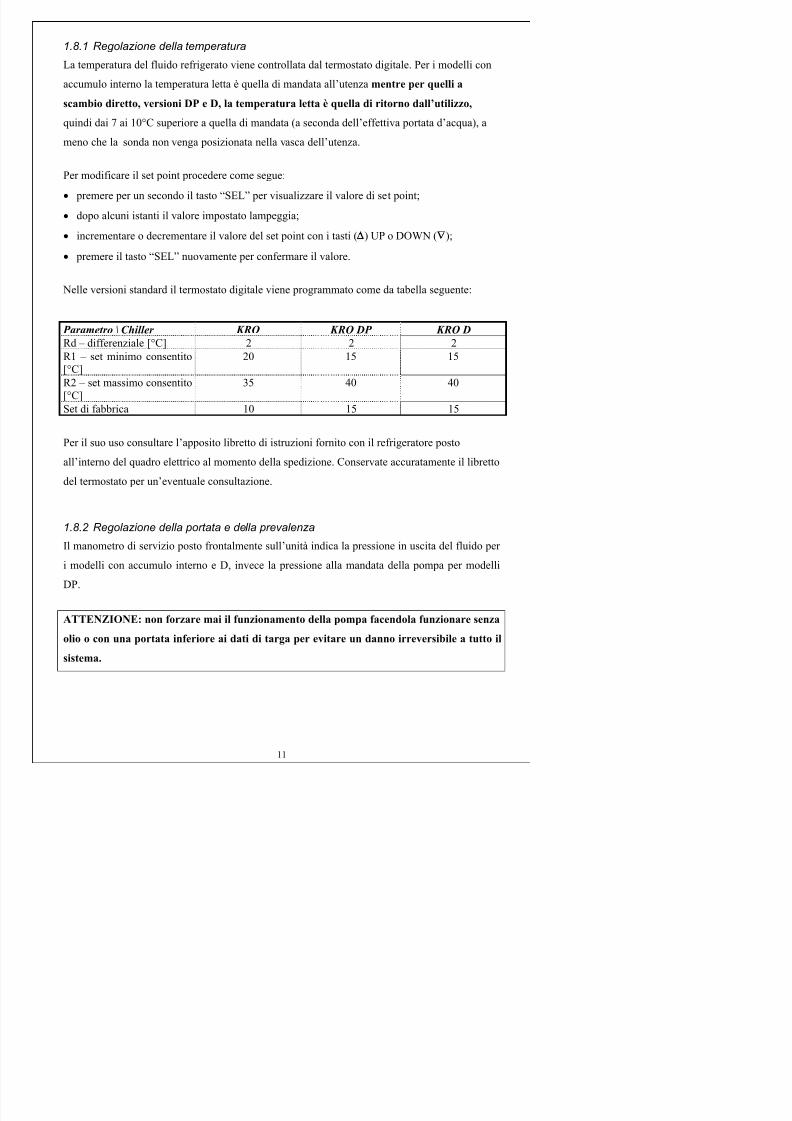
1.8.1 Regolazione della temperatura
La temperatura del fluido refrigerato viene controllata dal termostato digitale. Per i modelli con
accumulo interno la temperatura letta è quella di mandata all’utenza mentre per quelli a
scambio diretto, versioni DP e D, la temperatura letta è quella di ritorno dall’utilizzo,
quindi dai 7 ai 10°C superiore a quella di mandata (a seconda dell’effettiva portata d’acqua), a
meno che la sonda non venga posizionata nella vasca dell’utenza.
Per modificare il set point procedere come segue:
• premere per un secondo il tasto “SEL” per visualizzare il valore di set point;
• dopo alcuni istanti il valore impostato lampeggia;
• incrementare o decrementare il valore del set point con i tasti (
) UP o DOWN (∇
);
• premere il tasto “SEL” nuovamente per confermare il valore.
Nelle versioni standard il termostato digitale viene programmato come da tabella seguente:
Parametro \ Chiller KRO KRO DP KRO D
Rd – differenziale [°C] 2 2 2
R1 – set minimo consentito
[°C]
20 15 15
R2 – set massimo consentito
[°C]
35 40 40
Set di fabbrica 10 15 15
Per il suo uso consultare l’apposito libretto di istruzioni fornito con il refrigeratore posto
all’interno del quadro elettrico al momento della spedizione. Conservate accuratamente il libretto
del termostato per un’eventuale consultazione.
1.8.2 Regolazione della portata e della prevalenza
Il manometro di servizio posto frontalmente sull’unità indica la pressione in uscita del fluido per

7/17/2019 Kro 120 Da 21304
http://slidepdf.com/reader/full/kro-120-da-21304 12/75
1.8.3 Regolazione dell’allarme del flussostato (optionale)
I flussostati adottati sulla serie KRO sono di tipo elettromagnetico. All’avviamento può
verificarsi un falso allarme che richiede la taratura del componente. Per eseguirla è sufficientespostare lungo la scala graduata il sensore magnetico posto sul retro del flussostato regolandolo
sulle portate ottimali.
1.9 UNITA’ PER ESTERNO
Le unità adibite ad uso esterno devono essere appositamente ordinate per tale esecuzione. Tali
macchine sono costruite con le seguenti caratteristiche costruttive:
- parzializzazione del funzionamento dei due ventilatori, per temperature ambienti
inferiori a 15°C, con pressostato gas;
- verniciatura speciale della carpenteria per utilizzo esterno del chiller, con viti fi
fissaggio in accaio inox;
- quadro elettrico protetto da copertura di protezione removibile in accaio/plastica;
- lamiera interno macchina per protezione dei componenti per eventuale caduta pioggia
dall’alto del refrigeratore;
1.10 MANUTENZIONI E RIPARAZIONI
ATTENZIONE: Prima di effettuare qualsiasi tipo di intervento togliere tensione all'unità
agendo sia sull'interruttore posto a monte della linea che sull’interruttore generale posto
sul quadro di comando .
1.10.1 Manutenzione ordinaria
E’ consigliabile nei lunghi periodi di inattività scaricare l’acqua dell’impianto Prima di

7/17/2019 Kro 120 Da 21304
http://slidepdf.com/reader/full/kro-120-da-21304 13/75
In ambiente normale vengono programmati solitamente ogni tre mesi. In ambienti con particelle
d'olio in sospensione, l'intasamento della batteria avviene più rapidamente, e può essere risolto
con l'utilizzo di prodotti detergenti non caustici spruzzati sulle alette e poi soffiati con aria
compressa con pressione idonea e non elevata per non piegare o danneggiare le alette di
alluminio che eventualmente dovranno essere raddrizzate con gli appositi pettini di plastica. Si
raccomanda la pulizia periodica degli eventuali filtri sul circuito idraulico.
1.10.2 Pulizia della batteria condensante
La pulizia della batteria condensante è un’operazione molto importante per la buona e correttafunzionalità del refrigeratore. La frequenza di tale pulizia è funzione dell’ambiente in cui lavora
il chiller e dalla presenza o meno di un pannello filtro per il filtraggio dell’aria.
Per la pulizia della batteria condensante si può procedere in questo ordine:
- rimuovere e sollevare i due ventilatori (completi di griglia) dal tetto della macchina;
- rimuovere i due pannelli laterali;- proteggere i componenti dell’impianto frigo;
- spruzzare verticalmente un prodotto idoneo detergente non caustico, dall’alto verso il
basso, sulla batteria;
- ripristinare la condizione iniziale.
1.10.3 Pulizia della vasca
La vasca di accumulo interno al chiller è a cielo aperto. Togliendo un pannello laterale si può
accedere direttamente all’interno macchina, e svitando il coperchio, si può effettuare
direttamente la pulizia interna della vasca.
1.10.4 Manutenzione straordinaria
Pulizia dello scambiatore a piastre: in caso di sporcamente dello scambiatore a piastre, lato olio,
è sempre possibile la pulizia facendo circolare un liquido detergente apposito. Bisogna far
circolare il detergente dentro lo scambiatore: per un’efficace pulizia la portata del detergente

7/17/2019 Kro 120 Da 21304
http://slidepdf.com/reader/full/kro-120-da-21304 14/75
1.11 RICERCA GUASTI E DIAGNOSI RAPIDA
PROBLEMA CAUSA POSSIBILE SOLUZIONE
L’unità non si avvia.
Tutto è fermo.
Manca tensione all'unità, o
non vengono alimentati gli
ausiliari.
Fusibile di protezione degli
ausiliari bruciato.
Prima di aprire il quadro dell’unità, è necessario
ispezionare bene a monte gli automatismi che
alimentano e proteggono l’unità. Se non si
riscontrano anomalie aprire il quadro elettrico
dell’unità e verificare che sugli appositi
morsetti di entrata arrivi tensione regolare; in
caso affermativo accertarsi che arrivi tensione
regolare pure agli ausiliari e in ultima verificare
l’integrità del fusibile di protezione.
Raffreddamentoinsufficiente.
Compressore e pompa
funzionanti
L’unità non è raffreddata asufficienza.
Batteria o filtro molto sporchi.
L’aria in uscita dal
condensatore rientra in parte
nella batteria per la presenza di
ostacoli.
Pressione di alta elevata.
Provvedere alla pulizia del filtro aria o della batteria con detergenti non caustici.
Rimuovere eventuali ostacoli che provocano il
ricircolo dell’aria di condensazione.
Raffreddamentoinsufficiente. Pompa e
ventilatori funzionanti.
Spia rossa allarme accesa.
La condensazione nonavviene.
ATTENZIONE è pericoloso forzare ilfunzionamento della macchina.
Se l’unità è raffreddata con aria accertarsi che:
i ventilatori funzionino e che il senso di
rotazione sia esatto.
i filtri e le batterie siano puliti.
l’aria defluisca dal condensatore senza riciclarsi.
l’aria utilizzata non abbia una temperatura
superiore al consentito.Se l’unità è condensata con acqua (speciale)
accertarsi che l’acqua scorra regolarmente e
fuoriesca dal condensatore con temperatura
inferiore ai 40°C.
Raffreddamento
insufficiente.
Fluido condensante aria o
acqua in uscita dal
condensatore a
temperatura di poco
superiore alla temperatura
di entrata.
Pompa e ventilatore in
funzione
Il flusso da raffreddare ha una
portata insufficiente o è stata
richiesta una temperatura
inferiore ai limiti di catalogo.
Verificare la presenza del fluido da raffreddare e
la sua corretta portata.
Verificare l’efficienza della pompa ed il livello
della vasca.
Verificare le perdite di carico del circuito
idraulico asservito all’utenza.
Verificare che l’evaporatore non sia intasato da
sporcizia o da formazioni calcaree
penalizzandone lo scambio termico.

7/17/2019 Kro 120 Da 21304
http://slidepdf.com/reader/full/kro-120-da-21304 15/75
Il compressore è fermo e
molto caldo.
Pompa e ventilatore
funzionanti.
Nessuna spia di allarme
accesa.
Il compressore si è arrestato
per intervento della sicurezza
interna (klixon
termoamperom.) dovuto a
prolungato funzionamento
fuori dai limiti consentiti, o
per mancata partenza dovuto a
insufficiente alimentazione
elettrica.
Verificare che la temperatura e la quantità del
fluido da raffreddare, nonché la tensione e la
corrente in arrivo all’unità, sia conforme ai dati
di targa.
Verificare la funzionalità del condensatore.
Verificare che la carica di gas sia corretta.
Il tutto sembra
funzionare.
La corrente assorbita è
conforme a quella di
targa.La resa termica è
insufficiente.
Possibile errore nella
valutazione del fabbisogno
termico.
Verificare che l’amperaggio assorbito sia
regolare.
Verificare la pulizia e la funzionalità del
condensatore.
Verificare i calcoli del carico termico dasmaltire.
Spia allarme generale
accesa su unità trifase.
Blocco termico del
compressore o della pompa o
dei ventilatori dovuti a:
probabile mancanza di una
fase, insufficiente corrente
disponibile di fasenell’avviamento o
funzionamento termodinamico
fuori regime.
Verificare la tensione in arrivo ai componenti.
Verificare i contatti dei contattori.
Verificare il serraggio dei morsetti.
Verificare la corretta funzionalità del
condensatore.
Verificare che la temperatura dell’ambiente equella del fluido da raffreddare rientrino nei
limiti previsti.
Verificare la funzionalità meccanica della
pompa e dei ventilatori.
Verificare l’apertura di eventuali valvole di
intercettazione.
L’unità non raffredda o
non raggiunge il set point(KROD -DP)
Interviene il pressostato
differenziale.
Verificare il flusso nell’evaporatore.
1.12 MESSA FUORI SERVIZIO DELL’UNITA’
La demolizione del sistema frigorifero richiede l'intervento di personale specializzato in quanto
nel circuito termodinamico è presente gas refrigerante in pressione che può in caso di fugaviolenta essere pericoloso. E’ opportuno che il gas frigorigeno venga sempre recuperato sotto
forma liquida in bombole per essere consegnato ai centri di smaltimento così come per l’olio
presente nel compressore.

7/17/2019 Kro 120 Da 21304
http://slidepdf.com/reader/full/kro-120-da-21304 16/75
7/17/2019 Kro 120 Da 21304
http://slidepdf.com/reader/full/kro-120-da-21304 17/75
2.1 IMPORTANT SAFETY RELATED MEASURES
Read carefully these instructions and follow carefully the instructions contained in the
manual, especially those of CAUTION contained in squares and bold written. The
manufacturer refuses any responsibility for damages to persons or things due to non-
observance of instructions.
1 Always disconnect the unit from the mains before carrying out any inspection, maintenance or
cleaning.
2 Do not allow unqualified personnel to install, inspect or modify the unit. Operations on the
refrigeration circuit should be carried out only in presence of a refrigeration technician.
3 Do not work with free flames inside the unit.
4 Do not by pass the electrical safety devices and do not force the machine’s functioning..
5 Do not use the unit for applications different for those it has been specially designed for.
6 Do not install the unit outdoor or in explosive environment.
7 Do not install the unit on surfaces which are unstable or not designed to withstand its weight.
8 Keep this manual for future reference.
2.2 TRANSPORT AND HANDLING
When forwarding the units will be packed in board boxes and shipped on pallets. When
receiving the unit from the transporter, check the integrity of the packing and look for possible
damages due to transport. Any found damage should be put immediately on evidence to the
carrier in a written form. If any internal damage is suspected we advise to accept the delivery
reserving to control and claiming any damage to the carrier within 8 calendar days. The unit
must be stored only in its original vertical position,
otherwise warranty terms will be invalidated For

7/17/2019 Kro 120 Da 21304
http://slidepdf.com/reader/full/kro-120-da-21304 18/75
KRO90 KRO120 KRO150 KRO160 KRO180 KRO200
WEIGHT (kg) 222 232 242 248 258 268
DIMENSIONS
hxlxd(mm)
1260x615x1160 1260x615x1160 1260x615x1160 1260x715x1360 1260x715x1360 1260x715x1360
CAUTION: make sure to have firmly anchored the unit to avoid any overturning and
accidental falls during handling and lifting operations.
2.3 INSTALLATION OF THE CHILLER
In standard version the air used to cool the condenser is sucked laterally from both sides of the
unit and expelled upwards. During the installation it is important to make sure that the expelled
air doesn’t meet obstacles that could determine flow reductions and that it is not re-sucked
laterally
It is possible to invert the lateral panels so air can be sucked from the most convenient side.
If the operating ambient shows a high concentration of dust or oily materials make sure that the
machine is provided with a dust filter or an anti-grease filter instead of the grid side panel and
with an opposite blind panel.
Regarding outdoor installation the unit has to be specially ordered.
During installation, leave at least 800mm clearance from all sides of the unit for normal ordinary
and extraordinary maintenance operations. It should be also avoided to put the unit near heat and
dust sources.
All units with internal storage tank and a DP version are provided with a mechanical by-pass
valve to protect the system and are 1000 kPa (10 bars) tarred.
2.4 PROPER USE OF THE UNIT
Th i ll i f h hill f ll
7/17/2019 Kro 120 Da 21304
http://slidepdf.com/reader/full/kro-120-da-21304 19/75
may in no way meet obstacles and/or be re-sucked, not even partially, through the
condenser .
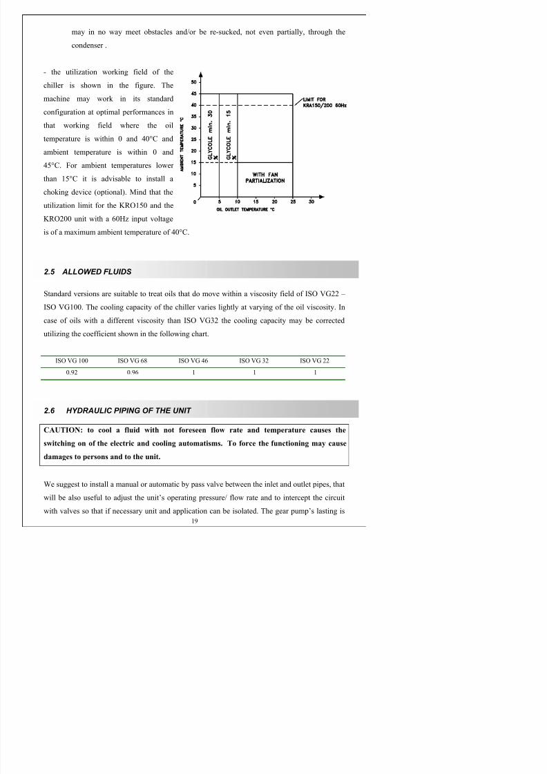
- the utilization working field of the
chiller is shown in the figure. The
machine may work in its standard
configuration at optimal performances in
that working field where the oil
temperature is within 0 and 40°C and
ambient temperature is within 0 and
45°C. For ambient temperatures lower
than 15°C it is advisable to install a
choking device (optional). Mind that the
utilization limit for the KRO150 and the
KRO200 unit with a 60Hz input voltage
is of a maximum ambient temperature of 40°C.
2.5 ALLOWED FLUIDS
Standard versions are suitable to treat oils that do move within a viscosity field of ISO VG22 –
ISO VG100. The cooling capacity of the chiller varies lightly at varying of the oil viscosity. In
case of oils with a different viscosity than ISO VG32 the cooling capacity may be corrected
utilizing the coefficient shown in the following chart.
ISO VG 100 ISO VG 68 ISO VG 46 ISO VG 32 ISO VG 22
0.92 0.96 1 1 1

7/17/2019 Kro 120 Da 21304
http://slidepdf.com/reader/full/kro-120-da-21304 20/75
limited by the presence of greasy particles. Should the fluid that has to be cooled has any solid
particles it is recommend to install a filter and to carry out all necessary periodical maintenances.
Following filtering degrees are recommended:
Suction: 60 µm Outlet: 10-25 µm
Any installed filter needs to be cleaned periodically.
The connecting pipes between refrigerator and application must have a suitable diameter to limit
the head pressure loss, they must be resistant to the maximum expected pressure and covered
with insulating and anti-condensate material.
Inlet pipes with an insufficient diameter do cause the pump’s cavitation getting in this way noisy.
The fluid’s outlet speed needs to be kept within 2 and 4 m/s.
The fluid’s sucking speed needs to be kept within 0,6 and 1 m/s.
CAUTION: The minimum absolute pressure allowed at the chiller’s inlet is 0.9 bars. Piping
of the hydraulic circuit needs to be dimensioned consequently.
CAUTION: in the DP version the pump is not allowed to work with a sucking
pressurization.
CAUTION: The fluid pump must always be operating. Never force it independently from
the compressor because it would cause damages to the refrigeration circuit.
Model KRO90 KRO 120 KRO150 KRO160 KRO180 KRO200
Hydraulic
fittings
1” 1” 1” 1” 1” 1”
Min. oil flowrate at 1000 kPa
45 [lit/min] 45 [lit/min] 45 [lit/min] 68 [lit/min] 68 [lit/min] 68 [lit/min]
2.6.1 Types and filling up of the circuits

7/17/2019 Kro 120 Da 21304
http://slidepdf.com/reader/full/kro-120-da-21304 21/75
Direct exchange chillers (without tank) KROD 90
200, KRODP 90
200. Filling-up will be
carried out from the user’s circuit. If the chiller should be connected to a close circuit the
installation of a specific pressurized oil expansion vessel is indispensable. The maximum
allowed pressure inside the circuit should be not higher than 20 bars.
2.7 ELECTRICAL CONNECTION OF THE UNIT
CAUTION: always disconnect the unit from the mains before carrying out any operation
on electric parts.
The electrical cabinet (IP54) is easily accessible from the front-side of the unit.
Respect the following recommendations:
Always connect the ground to an efficient PE terminal as required by the in force being norms.
Check the data on the unit’s name plate and select the correct cable section according to the
working amperage.
Select the power supply cable so that the voltage drop at start-up does not exceed 10% of the
nominal voltage.
Always provide the power supply line with a thermo–magnetic overload or exercise class aM
fuses as shown in the following chart and verify that the intervention point does correspond to
the absorption values.
KRO90 KRO120 KRO150 KRO160 KRO180 KRO200
Releasing current [A] (voltage400-3-50Hz)
12 16 16 20 20 25
Section [mm²] (voltage 400-3-
50Hz)
4 4 4 6 6 6
7/17/2019 Kro 120 Da 21304
http://slidepdf.com/reader/full/kro-120-da-21304 22/75
CAUTION: an insufficient power supply line or power coming from a local generator may
cause the cluing of the power contactors undoing so any protection device. It is therefore
indispensable that at compressor’s start-up voltage does not drop lower than 10%. If the
unit is supplied by a local generator in case of accidental stop of the same generator it is
indispensable to stop by hand the unit and re-start it only when the generator is rate
running.
2.8 START UP
CAUTION : In case of three phase power supply the internal motors are wired following
the R-S-T sequence of the principal terminals. We recommend to check the correct pump’s
direction rotation comparing it with the label on the pump’s motor or on the ventilator’s
motor.
Before start-up make sure that mains voltage and frequency correspond to those ones indicated
on the unit’s name plate and that water connections are well executed and eventual service
valves are open.
After connection to the main the control thermostat will light on. Make sure that the operating
water temperature does not exceed 25°C, unless the unit was not specifically requested for higher
values.
CAUTION : During the functioning of the unit, check that the compressor does not start
and stop more than 6 times in one hour.
2.8.1 Temperature adjusting
The temperature of the chilled fluid is controlled by a digital thermostat. On chillers with internal
storage the displayed temperature is the user’s inlet one, while for units with direct exchange,
DP and D versions, the displayed temperature is that one returning from the user, that

7/17/2019 Kro 120 Da 21304
http://slidepdf.com/reader/full/kro-120-da-21304 23/75
Parameter \ Chiller KRO KRO DP KRO D
Rd – differential [°C] 2 2 2
R1 – minimum allowed set [°C] 20 15 15
R2 – maximum allowed set [°C] 30 15 15
Factory set 10 15 15
Regarding the thermostat use, see its instructions book provided with the refrigerator, inside the
electric cabinet at forwarding. Keep accurately the thermostat’s book for future reference.
2.8.2 Flow rate and pressure head adjusting
The service manometer positioned on the front-side of the unit indicates the fluid’s outlet
pressure in case of models with internal storage and D versions, while in case of DP versions it
indicates the pump’s inlet pressure.
CAUTION: Never force the pump’s operation allowing to operate without oil and a minor
flow rate than that one indicated on the name plate to avoid an irreversible damage on the
whole system
2.8.3 Flow switch alarm adjusting (optional)
The flow switches adopted on the KRO series are electromagnetic. During the starting up can
happen a false alarm that requires the component’s setting. To operate this setting it is sufficient
to move along the graduated scale the magnetic sensor positioned on the back of the flow switch,
adjusting it on the optimum required.
2.9 OUTDOOR UNITS
Units equipped for an outdoor use need to be appositively ordered for such an execution. These
machines are built with following construction characteristics:
- choking of the two fans functioning, for ambient temperatures lower than 15°C, with a
gas pressure switch;

7/17/2019 Kro 120 Da 21304
http://slidepdf.com/reader/full/kro-120-da-21304 24/75
2.10 MAINTENANCE AND REPAIR
CAUTION: Before carrying out any kind of operation disconnect the mains using the
switch on top of the line and the mains switch on the unit’s control box.
2.10.1 Ordinary Maintenance
During long periods of inactivity it is always advisable to unload the water from the unit. Before
proceeding to open the electrical cabinet it is indispensable to disconnect the unit from the mains
opening the thermo-magnetic line switch and taking the necessary precautions in order that thesame one won’t be activated inadvertently. The only periodic maintenance required for a correct
functioning of the refrigeration circuit is cleaning the condenser coil and the air filter if there is
one on the side panel. If dirty, they may not allow a correct air flow and may determine a
considerable operating pressure increase causing the stop of the compressor by its thermo-
ampero-metric protection or the high pressure switch.Chiller will automatically re-start but on the long run these conditions will damage the
compressor irreversibly. The cleaning operations and their frequency do depend on the specific
working environment. In a normal environment cleaning should be done usually every three
months. Where greasy matters are suspended in the air, coil’s clogging will be rapidly resolved
spraying on the fins non-caustic detergents and blowing then on them compressed air with asuitable pressure to avoid to bend the aluminium fins, any bending needs to be corrected using
the apposite special plastic comb. A periodic cleaning of eventual filters on the hydraulic circuit
is recommended.
2.10.2 Cleaning of the condensing coil
Cleaning of the condensing coil is a very important operation to achieve a good and correct
functioning of the chiller. The frequency of such cleaning operation does depend on the specific
working environment of the chiller and the presence or not of a filter panel that filters the air.
T l th d i il it i ibl t d f ll i

7/17/2019 Kro 120 Da 21304
http://slidepdf.com/reader/full/kro-120-da-21304 25/75
2.10.3 Cleaning of the tank
The chiller’s internal storage tank is unsealed. Removing a side-panel it is possible to get direct
access inside the unit and unscrewing the cover it is possible to carry out directly the internal
cleaning of the tank.
2.10.4 Extraordinary maintenance
Cleaning of the plate heat-exchanger: in case that the plate heat-exchanger should get dirty on its
water-side, it is always possible to clean it putting in circulation some apposite liquid detergent.
It is necessary to let the detergent circulate inside the heat-exchanger: for an efficient cleaning
the detergent’s flow rate needs to be at least 1.5 times higher than the normal working flow rate.
Before re-starting the unit rinse it abundantly with water to remove any trace of detergent.
2.11 QUICK TROUBLE SHOOTING
PROBLEM POSSIBILE CAUSE SOLUTION
Unit does not run.
Nothing runs.
Connections to mains missing
or secondaries are not supplied.
Possible burning out of the
secondaries’ protection fuse.
Before opening the unit’s control box it is
necessary to check first the automatisms that
do supply and protect the unit. If no
anomalies are discovered do open the unit’s
electrical cabinet and check if on theapposite inlet terminals arrives regular
voltage; if affirmative make sure that regular
voltage arrives even on the secondary ones
and finally check the integrity of the
protection fuse.
Insufficient cooling.
Compressor and pump do
run
Insufficient cooling of the unit.
Condenser or filter very dirty.
The condenser outlet air enters partially again in the condenser
because of the presence of
obstacles.
Elevated head pressure.
Clean air filter and the coil using non–
caustic detergents.
Remove eventual obstacles that may causethe recycling of the condensate air.
7/17/2019 Kro 120 Da 21304
http://slidepdf.com/reader/full/kro-120-da-21304 26/75
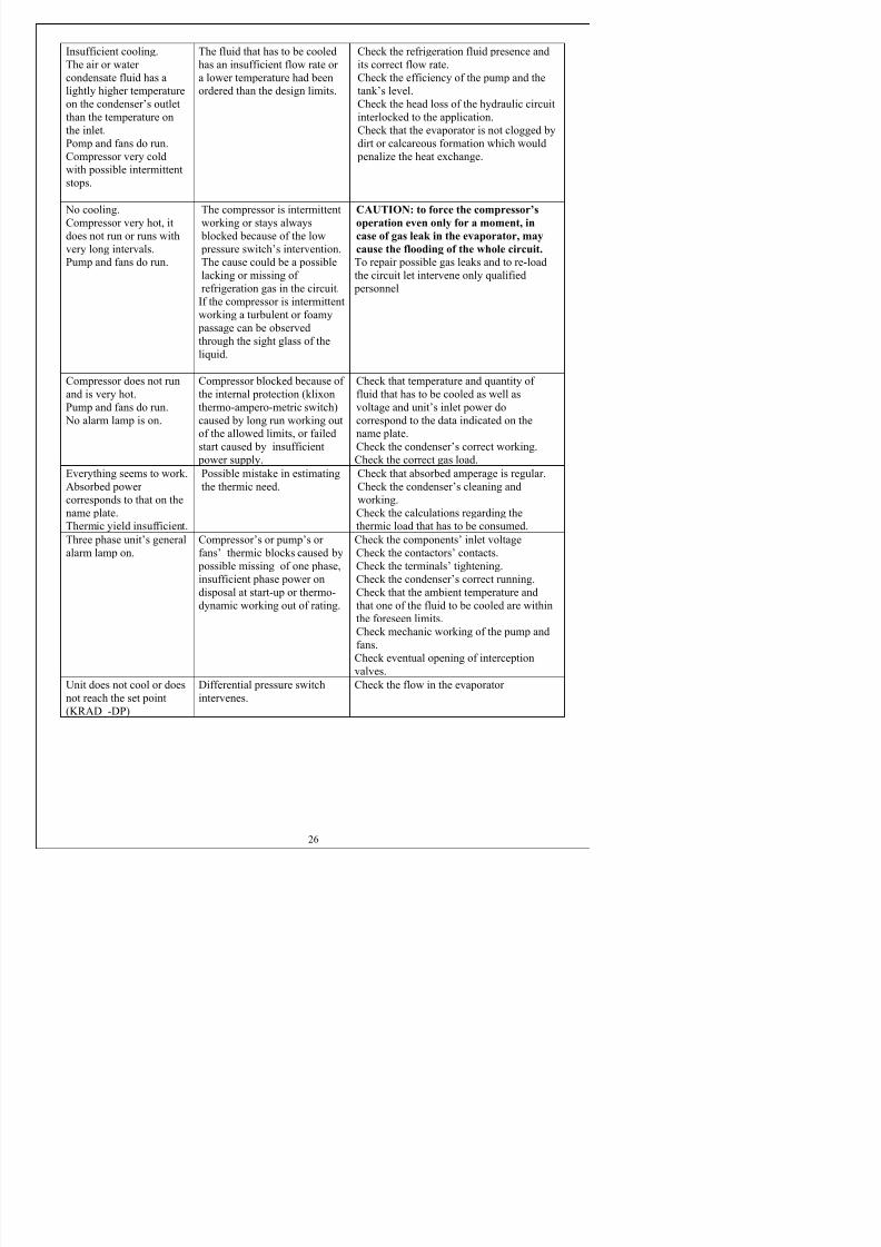
Insufficient cooling.
The air or water
condensate fluid has a
lightly higher temperature
on the condenser’s outlet
than the temperature onthe inlet.
Pomp and fans do run.
Compressor very cold
with possible intermittent
stops.
The fluid that has to be cooled
has an insufficient flow rate or
a lower temperature had been
ordered than the design limits.
Check the refrigeration fluid presence and
its correct flow rate.
Check the efficiency of the pump and the
tank’s level.
Check the head loss of the hydraulic circuit
interlocked to the application.Check that the evaporator is not clogged by
dirt or calcareous formation which would
penalize the heat exchange.
No cooling.
Compressor very hot, itdoes not run or runs with
very long intervals.
Pump and fans do run.
The compressor is intermittent
working or stays always blocked because of the low
pressure switch’s intervention.
The cause could be a possible
lacking or missing of
refrigeration gas in the circuit.
If the compressor is intermittent
working a turbulent or foamy
passage can be observedthrough the sight glass of the
liquid.
CAUTION: to force the compressor’s
operation even only for a moment, incase of gas leak in the evaporator, may
cause the flooding of the whole circuit.
To repair possible gas leaks and to re-load
the circuit let intervene only qualified
personnel
Compressor does not run
and is very hot.
Pump and fans do run.
No alarm lamp is on.
Compressor blocked because of
the internal protection (klixon
thermo-ampero-metric switch)
caused by long run working out
of the allowed limits, or failed
start caused by insufficient
power supply.
Check that temperature and quantity of
fluid that has to be cooled as well as
voltage and unit’s inlet power do
correspond to the data indicated on the
name plate.
Check the condenser’s correct working.
Check the correct gas load.
Everything seems to work.
Absorbed power
corresponds to that on the
name plate.
Thermic yield insufficient.
Possible mistake in estimating
the thermic need.
Check that absorbed amperage is regular.
Check the condenser’s cleaning and
working.
Check the calculations regarding the
thermic load that has to be consumed.
Three phase unit’s general
alarm lamp on.
Compressor’s or pump’s or
fans’ thermic blocks caused by possible missing of one phase,
insufficient phase power on
disposal at start-up or thermo-
dynamic working out of rating.
Check the components’ inlet voltage
Check the contactors’ contacts.Check the terminals’ tightening.
Check the condenser’s correct running.
Check that the ambient temperature and
that one of the fluid to be cooled are within
the foreseen limits

7/17/2019 Kro 120 Da 21304
http://slidepdf.com/reader/full/kro-120-da-21304 27/75
2.12 DECOMMISSIONING OF THE UNIT
The decommissioning of a chiller unit must be carried out only by qualified and properly
equipped technicians. Dangerous conditions may arise since the unit contains pressurised gas
that, in case of violent leak, it can be very dangerous. Refrigerant should be always recovered in
liquid status inside pressure vessels and should be brought to an authorised centre for its
disposal, the same must happen also for the oil inside the compressor.
This is explicitly required by law when decommissioning units are charged with CFC (chlor-
phlor carbids) refrigerants like R12 or R502, because they affect the Ozone layer if released into
the air.
The condensing coil and the copper tubing can be given to recycling companies.
CAUTION: It is dangerous to unload gas in presence of open flames.

7/17/2019 Kro 120 Da 21304
http://slidepdf.com/reader/full/kro-120-da-21304 28/75
7/17/2019 Kro 120 Da 21304
http://slidepdf.com/reader/full/kro-120-da-21304 29/75
Dichiarazione di conformità
Declaration of conformity
Konformitätserklärung
Déclaration de conformité
Declaración de conformidad
Noi / We / Wir / Nous / Nosotros
Kelvin Srl
Via E. Fermi –Z.A.I.
46040 Ponti Sul Mincio – Italia
dichiariamo che i prodotti della famiglia
declare that the products
Wir erklären, daß folgende Produkte
déclarez que les produits
declaramos que los productos
KRO
KROD
KRODP
E’ conforme a quanto prescritto dalle seguenti direttiveComply to the following european union directives
Zu den folgenden europäischen normen konform sindConformez-vous aux directives européennes suivantes des syndicats
Confórmese a las directivas europeas siguientes de la unión
89/336 CEE (EN50081/2-EN50082/2-EN61000/3/2)
73/23 CEE ( EN 60204/1 )
89/392 CEE (EN 291/1 – EN292/2 – EN1050)
97/23 CEE

7/17/2019 Kro 120 Da 21304
http://slidepdf.com/reader/full/kro-120-da-21304 30/75

7/17/2019 Kro 120 Da 21304
http://slidepdf.com/reader/full/kro-120-da-21304 31/75
AG Agitatore Agitator
AQ Acquablock Water level relay
AS Asametro AsameterBA By-pass automatico Automatic by-pass valve
BC Batteria condensatore Condenser
BE Batteria evaporatore Evaporator
BM By-pass manuale Manual by-pass
BZ Avvisatore acustico Buzzer
CA Condensatore di spunto Start capacityCO Compressore Compressor
CP Capillare Capillary
CR Condensatore di marcia Run capacity
CT Contattore Contactor
F Fusibile Fuse
FAC Filtro aria condensatore Condenser air filter
FAE Filtro aria evaporatore Evaporator air filter
FI Filtro liquido Liquid filter
FL Flussostato Flow switch
GR Gruppo di riempimento Fill-in system
HT Resistenza Heater
HU Umidostato Moisture teller
IA Interruttore automatico Breaker switchIG Interruttore generale Main switch
JO Jolly sfiato Automatic breather valve
KVC Regolatore di capacità frigorifera Cooling power controller
LE Livello elettrico Electric level
LI Livello visivo Level vewer
LS Lampada spia LampM Motore Motor
MN Manometro Gauge
PA Pressostato di alta High pressure switch
PB Pressostato di bassa Low pressure switch
CONDIZIONAMENTO E REFRIGERAZIONE

7/17/2019 Kro 120 Da 21304
http://slidepdf.com/reader/full/kro-120-da-21304 32/75

7/17/2019 Kro 120 Da 21304
http://slidepdf.com/reader/full/kro-120-da-21304 33/75
RT Temporizzatore Time relay
RV Spia liquido Liquid detector
RV Variatore di velocità Speed controller
RW Rubinetto acqua Water tap
SA Interruttore magneto termico Motor breaker switch
SE Sonda Probe
SG Solenoide gas caldo Hot gas solenoidSL Selettore Switch
SLG Solenoide gas Gas solenoid
SLW Elettrovalvola Electro valve
SV Scarico vasca Discharge
TA Termostato antigelo Antifreeze thermostat
TB Morsettiera Terminal boardsTC Relè termico Overload relay
TD Termostato differenziale Differential thermostat
TF Tappo fusibile Fuse cap
TM Termostato di minima Min. thermostat
TP Tappo di riempimento Fill-in cap
TR Trasformatore TransformerTS Termostato di servizio Themperature regulator
TX Termostato di massima Max. Thermostat
VA Vasca Tank
VAP Vasca accumulo pressurizzata Pressured tank
VC Ventilatore condensatore Condenser fan
VE Ventilatore evaporatore Evaporator fanVNR Valvola di carica Charge valve
VP Valvola pressostatica Pressostatic valve
VS Termometro Temperature display
CONDIZIONAMENTO E REFRIGERAZIONE

7/17/2019 Kro 120 Da 21304
http://slidepdf.com/reader/full/kro-120-da-21304 34/75

7/17/2019 Kro 120 Da 21304
http://slidepdf.com/reader/full/kro-120-da-21304 35/75
DatenblattData sheet
Fiche signalétique KKRROO112200DD AA2211330044
Dati tecniciDatos técnicos
DEU ENG FRA ITA ESP U.M.
Gewicht Weight Poids Peso Peso aproximado 232 Kg
Kältemittel Refrigerant Fluide frigorigène Mezzo frigorigeno Refrigerante R407cKältemittelmenge Refrigerant filling Quantité réfrigérant Quantità mezzo frigorigeno Carga refrigerante 5 Kg
Nennspannung Rated voltage Tension nominale Tensione nominale Alimentación eléctrica 400/3/50 V / ~ / HZ
Nennstrom Rated current Courant nominal Corrente nominale Consumo durante la marcha 15 A
Anlaufstrom Start-up current Courant de démarrage Corrente di spunto Consumo al arranque 65 A
Kühlleistung Cooling output Puissance frigorifique Potenza frigorifera Potenzia frigorífica 15150 W
Anschlussleistung Connected load Puissance connectée Potenza allacciata Potenzia total absorbida 6400 W
Geräuschpegel Noise level Niveau sonore Livello di rumorosità Nivel sonoro aprox. 69 dB(A)
Tank Tank capacity Capacité de réservoir Volume utile vasca Capacidad depósito acumulación / L
Lieferbar Fördehöhe Pressure available Hauteur d’élévation Pressione disponibile Presión disponible / Kpa
ABMESSUNGEN DIMENSIONS DIMENSIONS DIMENSIONI DIMENSIÓN
Höhe Height Hauteur Altezza Alto 1260 mm
Breite width Largeur Larghezza Largo 615 mm
Tiefe depth Profondeur Profondità Ancho 1160 mm
Frostschutzanteil Anti-frost agent content Part de l'antigel Percentuale antigelo Porcentual antihielo10 % min.
30 % max.Wir empfehlen: We recommend: Fournisseur préconisé : Nostra direttiva interna: Nuestra directriz interna:Hersteller Manufacturer Fabricant Fornitore Proveedor CLARIANTTyp Type Type Tipo Tipo Antifrogen N / L
OL OIL HUILE OLIO ACEITE Typ Type Type Tipo Tipo ISO VG 32

7/17/2019 Kro 120 Da 21304
http://slidepdf.com/reader/full/kro-120-da-21304 36/75

7/17/2019 Kro 120 Da 21304
http://slidepdf.com/reader/full/kro-120-da-21304 37/75

7/17/2019 Kro 120 Da 21304
http://slidepdf.com/reader/full/kro-120-da-21304 38/75
$ % - , 1

7/17/2019 Kro 120 Da 21304
http://slidepdf.com/reader/full/kro-120-da-21304 39/75
!"
#!
&'( )*&
+",-
#*
.%-
/
0
2 $
#" 1
#)&
&
3'& 224
"&4 224
&'( )*&
#
#& 5
#5( 5
6
6
6
6
6
6
6
6
6
$78
!"
+",-
.%-
"#
*4
*4
#8) &&(&8
&) %93 : ;<9 "=
01 -% ,1%$> 01 -% ,1%,
526:: '''?@4
7(5 2( *&
)*& 2(
6
6
#!3 1

7/17/2019 Kro 120 Da 21304
http://slidepdf.com/reader/full/kro-120-da-21304 40/75
$ % - , 1

7/17/2019 Kro 120 Da 21304
http://slidepdf.com/reader/full/kro-120-da-21304 41/75
!"
3"A !+
&'( )*&
+",-
#*
.%-
/
0
2 $
#" 1
3( @&@'3(
$
%
-
,
1
(
#!
3"A !+
3!+ +A
"BC"= +A
!B3B A"
" 3 B"=
" D!" C
" D!" C
#"D !+
D !E ""
"
-
-
-
-
-
-
-
-
-
-
@&
3"A 1

7/17/2019 Kro 120 Da 21304
http://slidepdf.com/reader/full/kro-120-da-21304 42/75
$ % - , 1
7/17/2019 Kro 120 Da 21304
http://slidepdf.com/reader/full/kro-120-da-21304 43/75
!"
3!+ +A
&'( )*&
+",-
#*
.%-
/
0
2 $
#" 1
))F
*?
$ $"
.
$
%
C
3!+ B33=
$78
3
3
+
E!$:-$
$))F
$"#
"$
19$
.
$
%
*
G ?+
$"
B +
3
$
*&
#!3!
$
%
%
*?
3
(
+
E!$:-$
$))F
" C,
E
$
%
*
G$+
"
B +
3
$
*&
E"
%
*?
3
(
+
E!$:-$
$))F
*
G$+
"
B +
3
*&
E"
*?
3
(
))F
&
$" C,
E
-
" :
,
"BC"=
1
" (AC,
E

7/17/2019 Kro 120 Da 21304
http://slidepdf.com/reader/full/kro-120-da-21304 44/75
$ % - , 1
7/17/2019 Kro 120 Da 21304
http://slidepdf.com/reader/full/kro-120-da-21304 45/75
!"
"BC"= +A
&'( )*&
+",-
#*
.%-
/
0
2 $
#" 1
$
+
$
7=!"#
!
,
+
$
A"
!
.
C
3"
C
C
3D
C
,
C
"
#
C $
$
C $
"
#
C %
%
"
"
"
""
,
$
-
C -
A
C ,
!!
"
-
-
,
"
"
"
,
C
C -
,
$
,
C ,
A
C ,
!!
"
,
,
,
"
"
"
C
C ,
,
"
,
1
"
,
"
"
"
#!3!
,
1
"
,
,
"
&
7
C
C
A"
""

7/17/2019 Kro 120 Da 21304
http://slidepdf.com/reader/full/kro-120-da-21304 46/75
$ % - , 1

7/17/2019 Kro 120 Da 21304
http://slidepdf.com/reader/full/kro-120-da-21304 47/75
!"
!B3B A"
&'( )*&
+",-
#*
.%-
/
0
$
2 $
#" 1
%
))F
&(
C
" 1
C
A"
""
$
C
$
C $
C %
%
;-<
3!D
;,<
))F
&(
-
C -
,
C ,
"C 3"B
7=!"#
1
C 1
C
C
;-<
3!D
;,<
))F
&(
C
C
"C 3"B
A"
C

7/17/2019 Kro 120 Da 21304
http://slidepdf.com/reader/full/kro-120-da-21304 48/75
$ % - , 1
&) &2 ))&4 ! 1

7/17/2019 Kro 120 Da 21304
http://slidepdf.com/reader/full/kro-120-da-21304 49/75
$
!"
" 3 B"=
&'( )*&
+",-
#*
.%-
/
0
%
2 $
#" 1
-
&2 ( 5 &2 &
&)
)
3
)
)*&
A&25 2(
5 &) &2
C
C
3!+ B33=
"BC"=
3
,
1
-
,

7/17/2019 Kro 120 Da 21304
http://slidepdf.com/reader/full/kro-120-da-21304 50/75
$ % - , 1

7/17/2019 Kro 120 Da 21304
http://slidepdf.com/reader/full/kro-120-da-21304 51/75
%
!"
" D!" C
&'( )*&
+",-
#*
.%-
/
0
-
2 $
#" 1
,
#
7
!
1
&
)
(
&
)
&
2
(
#* )
#* )
3( : 25
#
&(
4)*
)2&
&)
)*&
#
&(
(
#* 42
#* 42
E
C
"
7
"
3
3
!
+
B
3
3
=
.
C
3
!
+
B
3
3
=
.
C
3
!
+
B
3
3
=
%
.
C

7/17/2019 Kro 120 Da 21304
http://slidepdf.com/reader/full/kro-120-da-21304 52/75
$ % - , 1
% $ - $ % - $ $ $ $ - , ,

7/17/2019 Kro 120 Da 21304
http://slidepdf.com/reader/full/kro-120-da-21304 53/75
-
!"
" D!" C
&'( )*&
+",-
#*
.%-
/
0
,
2 $
#" 1
1
#
7
!
1
&
)
(
&
)
&
2
(
#* )
#* )
3( : 25
#
&(
4)*
)2&
&)
)*&
#
&(
(
#* 42
#* 42
E
+
+$
+%
+-
+,
+1
+
+
C
E!$:-$
E!$:-$
E!$:-$
E!$:-$
E!$:-$
E!$:-$
E!$:-$
E!$:-$
"
"
!
!
"
,
A
*
"
"
!
!
"
,
A
*
#
!
!
!
!
!
"
"
#
!
!
!
!
!
"
.
7
A
7
3
B
+
#
7
3
"
*
7
A
7
3
B
+
#
7
3
"
*
&
!
+
3
B
+
#
7
3
D
*
!
+
3
B
+
#
7
3
D
*
&
"
E
H
7
!
"
#
"
*
"
E
H
7
!
"
$
"
*
&
"
E
H
7
!
"
$
#
"
*
"
"
"
E
H
7
!
"
%
"
*
&
$
!
!
"
-
A
*
&
#
!
!
!
!
!
"
-
$
!
!
"
,
A
*
&
#
!
!
!
!
!
"
,
C
1
"
A
"
"
"
A
"
$
C
"
A
"
"
"
A
"
$
C
$
"
A
"
"
"
A
"
$
;
,
<
3
!
D
$
$
*
;
-
<
3
!
D
$
%
*
&
C
"
C
3
"
B
7
=
!
"
#
$
-
C
"
C
3
"
B
7
=
!
"
#
$
,
C
"
C
3
"
B
7
=
!
"
#
$
1
;
,
<
3
!
D
$
*
;
-
<
3
!
D
$
*
&
C
"
C
3
"
B
A
"
$
C
"
C
3
"
B
A
"
$
C
"
C
3
"
B
A
"
$

7/17/2019 Kro 120 Da 21304
http://slidepdf.com/reader/full/kro-120-da-21304 54/75
$ % - , 1
#* @&@'3 5
#" 1

7/17/2019 Kro 120 Da 21304
http://slidepdf.com/reader/full/kro-120-da-21304 55/75
,
!"
#"D !+
&'( )*&
+",-
#*
.%-
/
0
1
2 $
#" 1
#* (
#* )
&)
&
&(
#* 42
#&
#&
# &
))F:'(
(5
) )&?
35
3(
+
+
+
+
+$
+%
+-
+,
+1
+
+
.
3
C
C
C
C
C
C
C
C
E
3
E
3
A
A
3"
3D
"
"
E!$:-$
E!$:-$
E!$:-$
E!$:-$
E!$:-$
E!$:-$
E!$:-$
E!$:-$
E!$:-$
E!$:-$
E!$:-$
:3
:3
:3
:3
:3
:3
:3
:3
:3
:3
:3
:3
:3
:3
:3
$
$
$
$
$
$
$
$
$
9
9
9
9
9
9
9
9
9
9
9
9
9
9
9
9
9
%
%
%
$
$$

7/17/2019 Kro 120 Da 21304
http://slidepdf.com/reader/full/kro-120-da-21304 56/75
$ % - , 1
D )& # 1

7/17/2019 Kro 120 Da 21304
http://slidepdf.com/reader/full/kro-120-da-21304 57/75
1
!"
D !E ""
&'( )*&
+",-
#*
.%-
/
0
2 $
#" 1
) ( ") "& )*& &2 && & )*& 3:3
E
E
E
E
E
E
7
"
"
"
.
.
$"
+-
" (A
+-
"
+-
%
$9"#
$$ "#
$$ "#
$$ "#
$
9"$
#$+3
#$+3
"
+
+
C ,
D937" D!C C, EB
C ,
A937" D!C C, EB
C ,
7937" D!C C, EB
#"! "3
#!"#!I "#9 -$ +: I "# $:%7HI
"=I "#I #7"A! #!"# "
"=I "#I #7"A! #!"# "
"=I "#I #7"A! #!"# $"
!"! C$" D" !BA
##B9D"I H I
# 3!DI 3%,I #"D $)I 9$:0$J#
# 3!DI 3%,I #"D $)I 9$:0$J#
999$9:9
7!"I !B3BI # I:"#9#
7!"I !B3BI # I:"#9#
99999
99999
99999
D
E
E
E
#7!##
#"
#"
#!#"D"AA
#"
#"

7/17/2019 Kro 120 Da 21304
http://slidepdf.com/reader/full/kro-120-da-21304 58/75
7/17/2019 Kro 120 Da 21304
http://slidepdf.com/reader/full/kro-120-da-21304 59/75

7/17/2019 Kro 120 Da 21304
http://slidepdf.com/reader/full/kro-120-da-21304 60/75

7/17/2019 Kro 120 Da 21304
http://slidepdf.com/reader/full/kro-120-da-21304 61/75

7/17/2019 Kro 120 Da 21304
http://slidepdf.com/reader/full/kro-120-da-21304 62/75

7/17/2019 Kro 120 Da 21304
http://slidepdf.com/reader/full/kro-120-da-21304 63/75

7/17/2019 Kro 120 Da 21304
http://slidepdf.com/reader/full/kro-120-da-21304 64/75
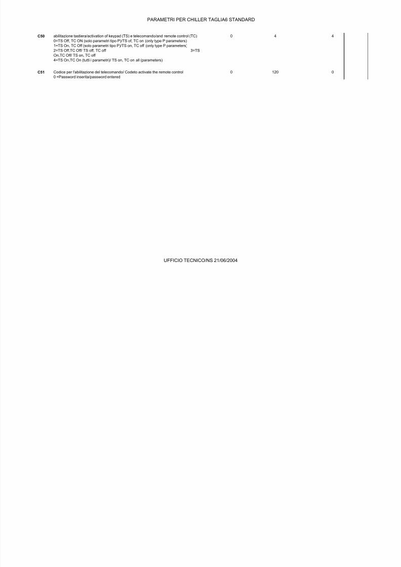
PARAMETRI PER CHILLER TAGLIA6 STANDARD
C41 OUT2:DIFFER./LOGICA / DIFFERENTIAL/LOGIG -100 +100 - (*)
C42 OUT3:DIPENDENZA/DEPENDENCE 0 15 - (*)

7/17/2019 Kro 120 Da 21304
http://slidepdf.com/reader/full/kro-120-da-21304 65/75
C43 OUT3:TIPO DI USCITA/TYPE OF OUTPUT 0 1 - (*)
C44 OUT3:INSERZIONE/INERGIZATION -100 +100 - (*)
C45 OUT3:DIFFER./LOGICA / DIFFERENTIAL/LOGIG -100 +100 - (*)
C46 OUT4:DIPENDENZA/DEPENDENCE 0 15 - (*)
C47 OUT4:TIPO DI USCITA/TYPE OF OUTPUT 0 1 - (*)
C48 OUT4:INSERZIONE/INERGIZATION -100 +100 - (*)
C49 OUT4:DIFFER./LOGICA / DIFFERENTIAL/LOGIG -100 +100 - (*)
(*) dipendono dal modello e dal modo di partenza/ (*) depends onthe model and starting mode
PREDISPOSIZIONE PER ABILITAZIONE TELECOMANDO/TASTIER/USE VIA REMOTE Min Max U.M. Def Nuovo
C50 abilitazione tastiera/activation of keypad (TS) e telecomando/and remote control (TC)0=TS Off, TC ON (solo parametri tipo P)/TS of, TC on (only type P parameters)
1=TS On, TC Off (solo parametri tipo P)/TS on, TC off (only type P parameters)
2=TS Off,TC Off/ TS off, TC off 3=TS
On,TC Off/ TS on, TC off
4=TS On,TC On (tutti i parametri)/ TS on, TC on all (parameters)
0 4 4
C51 Codice per l'abilitazione del telecomando/ Codeto activate the remote control
0 =Password inserita/password entered
0 120 0
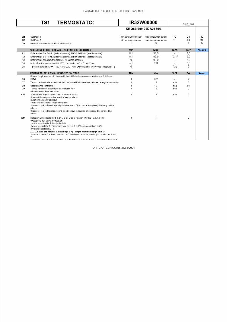
St1 Set Point 1 min.sonda/min.sensor max sonda/max sensor °C 20 40
St2 Set Point 2 min.sonda/min.sensor max sonda/max sensor °C 40 25
C0 Modo di funzionamento/ Mode of operation 1 9 2 9
SELEZIONE DEI DIFFERENZIALI/SETTING DIFFERENTIALS Min Max U.M. Def Nuovo
P1 Differenziale Set Point 1 (valore assoluto) /Diff.of Set Point (absolute value) 0,1 99,9 - 2,0
P2 Differenziale Set Point 2 (valore assoluto) /Diff.of Set Point (absolute value) 0,1 99,9 °C/°F 2,0
P3 Differenziale zona Neutra (Modi 3,4,5) (valore assoluto) 0 99,9 - 2,0
C4 Autorità.Attiva solo nei modelli NTC, con Modo 1 o 2 e C19 =2,3 o4 -2,0 2,0 - 0,5
C5 Tipo di regolazione : 0=P+1cONTROL ACTION: 0=Propotional (P) 1=Prop+Integral (P+I) 0 1 flag 0
KRO60/90/120DA21304
TS2 TERMOSTATO: IR32W00000 FILE_187
UFFICIO TECNICO/NS 21/06/2004

7/17/2019 Kro 120 Da 21304
http://slidepdf.com/reader/full/kro-120-da-21304 66/75

7/17/2019 Kro 120 Da 21304
http://slidepdf.com/reader/full/kro-120-da-21304 67/75

7/17/2019 Kro 120 Da 21304
http://slidepdf.com/reader/full/kro-120-da-21304 68/75

7/17/2019 Kro 120 Da 21304
http://slidepdf.com/reader/full/kro-120-da-21304 69/75

7/17/2019 Kro 120 Da 21304
http://slidepdf.com/reader/full/kro-120-da-21304 70/75
PARAMETRI PER CHILLER TAGLIA6 STANDARD
C31 Stato uscite in caso di allarme digitale
Output status in the event of alarm condition detected via digital input
0=tutte le uscite OFF/all outputs OFF 1=tutte le
O / O
0 3 0

7/17/2019 Kro 120 Da 21304
http://slidepdf.com/reader/full/kro-120-da-21304 71/75
uscite ON/all outputs ON
2=OFF le uscite con funzion.Reverse, inalterae le altre/outputs in Reverse OFF, unchanged
the others 3=OFF le uscite con
funzionamento Direct, inalterate le altre/outputs in Direct OFF, unchanged the others
ALTRE PREDISPOSIZIONI / OTHERS Min Max U.M. Def Nuovo
C32 Indirizzo per connessione seriale/Adress of unit for serial connection 1 16 1
PARAMETRI FUNZIONAMENTO SPECIALE/SPECIAL PARAMETERS Min Max U.M. Def Nuovo
C33 funzionamento speciale 0=no, 1=si/special Mode of operation: 0=no, 1=yes Primadella modifica accertarsi di aver selezionato e programmato il Modo di partenza ( C)
desiderato
Before modifying C33 be sure you have set and programmed the Starting Mode C0
0 1 - 0
C34 OUT1:DIPENDENZA/DEPENDENCE 0 15 - (*)
C35 OUT1:TIPO DI USCITA/TYPE OF OUTPUT 0 1 - (*)
C36 OUT1:INSERZIONE/INERGIZATION -100 +100 - (*)
C37 OUT1:DIFFER./LOGICA / DIFFERENTIAL/LOGIG -100 +100 - (*)
C38 OUT2:DIPENDENZA/DEPENDENCE 0 15 - (*)
C39 OUT2:TIPO DI USCITA/TYPE OF OUTPUT 0 1 - (*)
C40 OUT2:INSERZIONE/INERGIZATION -100 +100 - (*)
C41 OUT2:DIFFER./LOGICA / DIFFERENTIAL/LOGIG -100 +100 - (*)
C42 OUT3:DIPENDENZA/DEPENDENCE 0 15 - (*)
C43 OUT3:TIPO DI USCITA/TYPE OF OUTPUT 0 1 - (*)
C44 OUT3:INSERZIONE/INERGIZATION -100 +100 - (*)
C45 OUT3:DIFFER./LOGICA / DIFFERENTIAL/LOGIG -100 +100 - (*)
C46 OUT4:DIPENDENZA/DEPENDENCE 0 15 - (*)
C47 OUT4:TIPO DI USCITA/TYPE OF OUTPUT 0 1 - (*)
C48 OUT4:INSERZIONE/INERGIZATION -100 +100 - (*)
C49 OUT4:DIFFER./LOGICA / DIFFERENTIAL/LOGIG -100 +100 - (*)
(*) dipendono dal modello e dal modo di partenza/ (*) depends onthe model and starting mode
PREDISPOSIZIONE PER ABILITAZIONE TELECOMANDO/TASTIER/USE VIA REMOTE Min Max U.M. Def Nuovo
UFFICIO TECNICO/NS 21/06/2004

7/17/2019 Kro 120 Da 21304
http://slidepdf.com/reader/full/kro-120-da-21304 72/75
PARAMETRI PER CHILLER TAGLIA6 STANDARD
C50 abilitazione tastiera/activation of keypad (TS) e telecomando/and remote control (TC)
0=TS Off, TC ON (solo parametri tipo P)/TS of, TC on (only type P parameters)
1=TS On, TC Off (solo parametri tipo P)/TS on, TC off (only type P parameters)
2=TS Off TC Off/ TS off TC off 3=TS
0 4 4
7/17/2019 Kro 120 Da 21304
http://slidepdf.com/reader/full/kro-120-da-21304 73/75
2=TS Off,TC Off/ TS off, TC off 3=TS
On,TC Off/ TS on, TC off
4=TS On,TC On (tutti i parametri)/ TS on, TC on all (parameters)
C51 Codice per l'abilitazione del telecomando/ Codeto activate the remote control
0 =Password inserita/password entered
0 120 0
UFFICIO TECNICO/NS 21/06/2004

7/17/2019 Kro 120 Da 21304
http://slidepdf.com/reader/full/kro-120-da-21304 74/75
7/17/2019 Kro 120 Da 21304
http://slidepdf.com/reader/full/kro-120-da-21304 75/75
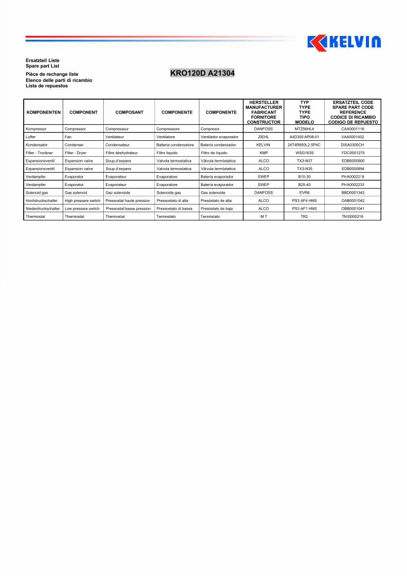
Ersatzteil ListeSpare part List
Pièce de rechange liste KRO120D A21304
Elenco delle parti di ricambioLista de repuestos
KOMPONENTEN COMPONENT COMPOSANT COMPONENTE COMPONENTE MANUFACTURER
HERSTELLER
FABRICANTFORNITORE
CONSTRUCTOR
TYP
TYPETYPETIPO
MODELO
ERSATZTEIL CODE
SPARE PART CODEREFERENCECODICE DI RICAMBIO
CODIGO DE REPUESTO
Kompressor Compressor Compresseur Compressore Compresor DANFOSS MTZ56HL4 CAA0001116
Lüfter Fan Ventilateur Ventilatore Ventilador evaporador ZIEHL A4D350 AP08-01 VAA0001402
Kondensator Condenser Condensateur Batteria condensatore Batería condensador KELVIN 24T4R850L2.5P4C DISA0300CH
Filter - Trockner Filter - Dryer Filtre déshydrateur Filtro liquido Filtro de líquido KMP WSG163S FDC0001270
Expansionsventil Expansion valve Soup.d’expans Valvola termostatica Válvula termóstatica ALCO TX3-N37 EDB0000900
Expansionsventil Expansion valve Soup.d’expans Valvola termostatica Válvula termóstatica ALCO TX3-N35 EDB0000894
Verdampfer Evaporator Evaporateur Evaporatore Batería evaporador SWEP B10-30 PHA0002218
Verdampfer Evaporator Evaporateur Evaporatore Batería evaporador SWEP B25-40 PHA0002233
Solenoid gas Gas solenoid Gaz solenoide Solenoide gas Gas solenoide DANFOSS EVR6 BBD0001342
Hochdruckschalter High pressare switch Pressostat haute pression Pressostato di alta Presóstato de alta ALCO PS3 AF4 HNS OAB0001042
Niederdruckschalter Low pressare switch Pressostat basse pression Pressostato di bassa Presóstato de baja ALCO PS3 AF1 HNS OBB0001041
Thermostat Thermostat Thermostat Termostato Termóstato IMIT TR2 TMI0000218