in4728a
TRANSCRIPT
DeviceVZ (V)
ZZ(Ω)
IZT (mA)
ZZK(Ω)
IZK(mA)
VR(V)
IR(µA)
ISURGE(mA)
IZM(mA)
1N4728A1N4729A1N4730A1N4731A
3.33.63.94.3
10109.09.0
76696458
400400400400
1.01.01.01.0
1.01.01.01.0
1001005010
1,3801,2601,1901,070
276252234217
1N4732A1N4733A1N4734A1N4735A
4.75.15.66.2
8.07.05.02.0
53494541
500550600700
1.01.01.01.0
1.01.02.03.0
10101010
970890810730
193178162146
1N4736A1N4737A1N4738A1N4739A
6.87.58.29.1
3.54.04.55.0
37343128
700700700700
1.00.50.50.5
4.05.06.07.0
10101010
660605550500
133121110100
1N4740A1N4741A1N4742A1N4743A1N4744A
1011121315
7.08.09.01014
2523211917
700700700700700
0.250.250.250.250.25
7.68.49.19.911.4
105.05.05.05.0
454414380344304
9183766961
1N4745A1N4746A1N4747A1N4748A
16182022
16202223
15.514
12.511.5
700750750750
0.250.250.250.25
12.213.715.216.7
5.05.05.05.0
285250225205
57504541
1N4749A1N4750A1N4751A1N4752A
24273033
25354045
10.59.58.57.5
750750
1,0001,000
0.250.250.250.25
18.220.622.825.1
5.05.05.05.0
190170150135
38343027
VF Foward Voltage = 1.2 V Maximum @ IF = 200 mA for all 1N4700 series
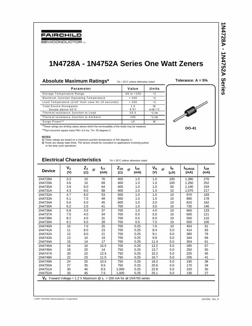
1N4728A - 1N4752A Series One Watt Zeners
Absolute Maximum Ratings* TA = 25°C unless otherwise noted Tolerance: A = 5%
Electrical Characteristics TA = 25°C unless otherwise noted
@@@
NOTES:1) These ratings are based on a maximum junction temperature of 200 degrees C.2) These are steady state limits. The factory should be consulted on applications involving pulsed or low duty cycle operations.
*These ratings are limiting values above which the serviceability of the diode may be impaired.
**Non-recurrent square wave PW= 8.3 ms, TA= 55 degrees C.
P a ra m e te r V a lu e U n its
S to ra g e T e m p e ra tu re R a n g e -6 5 to + 2 0 0 °C
M a xim u m J u n c tio n O p e ra tin g T e m p e ra tu re + 2 0 0 °C
L e a d T e m p e ra tu re (1 /1 6 ” fro m c a s e fo r 1 0 s e c o n d s ) + 2 3 0 °C
T o ta l D e v ic e D is s ip a tio nD e ra te a b o ve 5 0 °C
1 .06 .6 7
Wm W /°C
T h e rm a l re s is ta n c e J u n c tio n to L e a d 5 3 .5 °C /W
T h e rm a l re s is ta n c e J u n c tio n to A m b ie n t 1 0 0 °C /W
S u rg e P o w e r** 1 0 W
1N4728A
- 1N4752A
Series
DO-41
1997 Fairchild Semiconductor Corporation 1N4700A Rev. B
TRADEMARKS
ACEx™CoolFET™CROSSVOLT™E2CMOSTM
FACT™FACT Quiet Series™FAST®
FASTr™GTO™HiSeC™
The following are registered and unregistered trademarks Fairchild Semiconductor owns or is authorized to use and isnot intended to be an exhaustive list of all such trademarks.
LIFE SUPPORT POLICY
FAIRCHILD’S PRODUCTS ARE NOT AUTHORIZED FOR USE AS CRITICAL COMPONENTS IN LIFE SUPPORTDEVICES OR SYSTEMS WITHOUT THE EXPRESS WRITTEN APPROVAL OF FAIRCHILD SEMICONDUCTOR CORPORATION.As used herein:
ISOPLANAR™MICROWIRE™POP™PowerTrench™QS™Quiet Series™SuperSOT™-3SuperSOT™-6SuperSOT™-8TinyLogic™
1. Life support devices or systems are devices orsystems which, (a) are intended for surgical implant intothe body, or (b) support or sustain life, or (c) whosefailure to perform when properly used in accordancewith instructions for use provided in the labeling, can bereasonably expected to result in significant injury to theuser.
2. A critical component is any component of a lifesupport device or system whose failure to perform canbe reasonably expected to cause the failure of the lifesupport device or system, or to affect its safety oreffectiveness.
PRODUCT STATUS DEFINITIONS
Definition of Terms
Datasheet Identification Product Status Definition
Advance Information
Preliminary
No Identification Needed
Obsolete
This datasheet contains the design specifications forproduct development. Specifications may change inany manner without notice.
This datasheet contains preliminary data, andsupplementary data will be published at a later date.Fairchild Semiconductor reserves the right to makechanges at any time without notice in order to improvedesign.
This datasheet contains final specifications. FairchildSemiconductor reserves the right to make changes atany time without notice in order to improve design.
This datasheet contains specifications on a productthat has been discontinued by Fairchild semiconductor.The datasheet is printed for reference information only.
Formative orIn Design
First Production
Full Production
Not In Production
DISCLAIMER
FAIRCHILD SEMICONDUCTOR RESERVES THE RIGHT TO MAKE CHANGES WITHOUT FURTHERNOTICE TO ANY PRODUCTS HEREIN TO IMPROVE RELIABILITY, FUNCTION OR DESIGN. FAIRCHILDDOES NOT ASSUME ANY LIABILITY ARISING OUT OF THE APPLICATION OR USE OF ANY PRODUCTOR CIRCUIT DESCRIBED HEREIN; NEITHER DOES IT CONVEY ANY LICENSE UNDER ITS PATENTRIGHTS, NOR THE RIGHTS OF OTHERS.